US9846086B1 - System and method for time-temperature monitoring of transportable goods - Google Patents
System and method for time-temperature monitoring of transportable goods Download PDFInfo
- Publication number
- US9846086B1 US9846086B1 US14/076,904 US201314076904A US9846086B1 US 9846086 B1 US9846086 B1 US 9846086B1 US 201314076904 A US201314076904 A US 201314076904A US 9846086 B1 US9846086 B1 US 9846086B1
- Authority
- US
- United States
- Prior art keywords
- temperature
- time
- transportable
- electronic device
- transportable good
- Prior art date
- Legal status (The legal status is an assumption and is not a legal conclusion. Google has not performed a legal analysis and makes no representation as to the accuracy of the status listed.)
- Active, expires
Links
- 238000012544 monitoring process Methods 0.000 title claims abstract description 50
- 238000000034 method Methods 0.000 title claims abstract description 36
- 238000003860 storage Methods 0.000 claims description 43
- 238000004891 communication Methods 0.000 claims description 33
- 230000008859 change Effects 0.000 claims description 22
- 230000004044 response Effects 0.000 claims description 19
- 238000001914 filtration Methods 0.000 claims 4
- 238000009529 body temperature measurement Methods 0.000 claims 3
- 239000000523 sample Substances 0.000 description 50
- LYCAIKOWRPUZTN-UHFFFAOYSA-N Ethylene glycol Chemical compound OCCO LYCAIKOWRPUZTN-UHFFFAOYSA-N 0.000 description 28
- 238000012384 transportation and delivery Methods 0.000 description 26
- 230000007704 transition Effects 0.000 description 20
- 230000015654 memory Effects 0.000 description 19
- 239000003570 air Substances 0.000 description 18
- 235000013305 food Nutrition 0.000 description 17
- 238000011068 loading method Methods 0.000 description 17
- YGJHZCLPZAZIHH-UHFFFAOYSA-N N-Nitrosodi-n-butylamine Chemical compound CCCCN(N=O)CCCC YGJHZCLPZAZIHH-UHFFFAOYSA-N 0.000 description 15
- 239000003814 drug Substances 0.000 description 10
- 229940079593 drug Drugs 0.000 description 10
- 238000012806 monitoring device Methods 0.000 description 10
- 230000008569 process Effects 0.000 description 10
- 238000005057 refrigeration Methods 0.000 description 9
- 238000012545 processing Methods 0.000 description 8
- 238000010586 diagram Methods 0.000 description 7
- 230000006870 function Effects 0.000 description 7
- 230000000694 effects Effects 0.000 description 6
- 230000008901 benefit Effects 0.000 description 5
- 238000004364 calculation method Methods 0.000 description 4
- 238000004422 calculation algorithm Methods 0.000 description 3
- 238000004519 manufacturing process Methods 0.000 description 3
- 230000007246 mechanism Effects 0.000 description 3
- 238000013439 planning Methods 0.000 description 3
- 239000003990 capacitor Substances 0.000 description 2
- 238000013500 data storage Methods 0.000 description 2
- 230000007123 defense Effects 0.000 description 2
- 238000013461 design Methods 0.000 description 2
- 238000009826 distribution Methods 0.000 description 2
- WGCNASOHLSPBMP-UHFFFAOYSA-N hydroxyacetaldehyde Natural products OCC=O WGCNASOHLSPBMP-UHFFFAOYSA-N 0.000 description 2
- 230000000977 initiatory effect Effects 0.000 description 2
- 238000003780 insertion Methods 0.000 description 2
- 230000037431 insertion Effects 0.000 description 2
- 238000012986 modification Methods 0.000 description 2
- 230000004048 modification Effects 0.000 description 2
- 239000002994 raw material Substances 0.000 description 2
- 238000012358 sourcing Methods 0.000 description 2
- 238000012546 transfer Methods 0.000 description 2
- 235000011299 Brassica oleracea var botrytis Nutrition 0.000 description 1
- 235000017647 Brassica oleracea var italica Nutrition 0.000 description 1
- 240000003259 Brassica oleracea var. botrytis Species 0.000 description 1
- 230000009471 action Effects 0.000 description 1
- 230000006978 adaptation Effects 0.000 description 1
- 239000012080 ambient air Substances 0.000 description 1
- 238000004458 analytical method Methods 0.000 description 1
- 238000013459 approach Methods 0.000 description 1
- 238000012550 audit Methods 0.000 description 1
- XMQFTWRPUQYINF-UHFFFAOYSA-N bensulfuron-methyl Chemical compound COC(=O)C1=CC=CC=C1CS(=O)(=O)NC(=O)NC1=NC(OC)=CC(OC)=N1 XMQFTWRPUQYINF-UHFFFAOYSA-N 0.000 description 1
- 238000003339 best practice Methods 0.000 description 1
- 230000005540 biological transmission Effects 0.000 description 1
- 230000001413 cellular effect Effects 0.000 description 1
- 238000010276 construction Methods 0.000 description 1
- 230000001276 controlling effect Effects 0.000 description 1
- 238000007796 conventional method Methods 0.000 description 1
- 230000008878 coupling Effects 0.000 description 1
- 238000010168 coupling process Methods 0.000 description 1
- 238000005859 coupling reaction Methods 0.000 description 1
- 238000001514 detection method Methods 0.000 description 1
- 201000010099 disease Diseases 0.000 description 1
- 208000037265 diseases, disorders, signs and symptoms Diseases 0.000 description 1
- 238000005516 engineering process Methods 0.000 description 1
- 238000011156 evaluation Methods 0.000 description 1
- 239000000446 fuel Substances 0.000 description 1
- 230000006872 improvement Effects 0.000 description 1
- 238000012905 input function Methods 0.000 description 1
- 230000007787 long-term memory Effects 0.000 description 1
- 230000007774 longterm Effects 0.000 description 1
- 239000000463 material Substances 0.000 description 1
- 230000003287 optical effect Effects 0.000 description 1
- 238000004806 packaging method and process Methods 0.000 description 1
- 230000002265 prevention Effects 0.000 description 1
- 230000001737 promoting effect Effects 0.000 description 1
- 230000001105 regulatory effect Effects 0.000 description 1
- 239000004065 semiconductor Substances 0.000 description 1
- 238000004088 simulation Methods 0.000 description 1
- 239000007787 solid Substances 0.000 description 1
- 238000012421 spiking Methods 0.000 description 1
- 230000003068 static effect Effects 0.000 description 1
- 239000000126 substance Substances 0.000 description 1
- 230000009885 systemic effect Effects 0.000 description 1
- 210000003813 thumb Anatomy 0.000 description 1
Images


Classifications
-
- G—PHYSICS
- G01—MEASURING; TESTING
- G01K—MEASURING TEMPERATURE; MEASURING QUANTITY OF HEAT; THERMALLY-SENSITIVE ELEMENTS NOT OTHERWISE PROVIDED FOR
- G01K3/00—Thermometers giving results other than momentary value of temperature
- G01K3/02—Thermometers giving results other than momentary value of temperature giving means values; giving integrated values
- G01K3/04—Thermometers giving results other than momentary value of temperature giving means values; giving integrated values in respect of time
-
- G—PHYSICS
- G01—MEASURING; TESTING
- G01K—MEASURING TEMPERATURE; MEASURING QUANTITY OF HEAT; THERMALLY-SENSITIVE ELEMENTS NOT OTHERWISE PROVIDED FOR
- G01K1/00—Details of thermometers not specially adapted for particular types of thermometer
- G01K1/02—Means for indicating or recording specially adapted for thermometers
- G01K1/024—Means for indicating or recording specially adapted for thermometers for remote indication
-
- G—PHYSICS
- G01—MEASURING; TESTING
- G01K—MEASURING TEMPERATURE; MEASURING QUANTITY OF HEAT; THERMALLY-SENSITIVE ELEMENTS NOT OTHERWISE PROVIDED FOR
- G01K1/00—Details of thermometers not specially adapted for particular types of thermometer
- G01K1/02—Means for indicating or recording specially adapted for thermometers
- G01K1/026—Means for indicating or recording specially adapted for thermometers arrangements for monitoring a plurality of temperatures, e.g. by multiplexing
-
- G—PHYSICS
- G01—MEASURING; TESTING
- G01K—MEASURING TEMPERATURE; MEASURING QUANTITY OF HEAT; THERMALLY-SENSITIVE ELEMENTS NOT OTHERWISE PROVIDED FOR
- G01K11/00—Measuring temperature based upon physical or chemical changes not covered by groups G01K3/00, G01K5/00, G01K7/00 or G01K9/00
- G01K11/06—Measuring temperature based upon physical or chemical changes not covered by groups G01K3/00, G01K5/00, G01K7/00 or G01K9/00 using melting, freezing, or softening
-
- G—PHYSICS
- G01—MEASURING; TESTING
- G01K—MEASURING TEMPERATURE; MEASURING QUANTITY OF HEAT; THERMALLY-SENSITIVE ELEMENTS NOT OTHERWISE PROVIDED FOR
- G01K7/00—Measuring temperature based on the use of electric or magnetic elements directly sensitive to heat ; Power supply therefor, e.g. using thermoelectric elements
- G01K7/42—Circuits effecting compensation of thermal inertia; Circuits for predicting the stationary value of a temperature
Definitions
- Automatic electronic time-temperature monitoring systems may be used to reduce reliance on labor-based monitoring systems, which is expensive and prone to error.
- proper handling requires refrigerated, heated, or temperature controlled facilities and transportation equipment, to assure shelf quality, longevity, and safety.
- Automatic temperature monitoring devices allow operators and supervisors to identify the time-temperature conditions of a commodity so that an educated evaluation of the commodity's compliance with safety and standards are achieved.
- Cost and reliability efficiencies may be realized by facilitating the time-temperature monitoring to be delivered as accurately as possible and in real time.
- accurate time-temperature monitoring is difficult in real time as temperatures of a commodity in a warehouse have reached equilibrium with temperature sensors within the facility; however, in the transition to a refrigerated trailer, for example, temperature probes in the trailer may only measure temperatures of the air in the trailer instead of the core commodity temperature.
- This phenomenon may create areas of time-temperature discontinuity between storage, transportation, and delivery facilities and equipment, creating uncertainty regarding the temperature quality of the shipment and direct assignment of responsibility for deviations from a specified or acceptable temperature quality.
- Embodiments discussed herein include an enhanced method of automated, electronic, real-time time-temperature monitoring of transportable goods, for example, refrigerated food and drug commodities.
- the method efficiently transitions from storage (e.g., warehouse) to transportation asset (e.g., refrigerated container, trailer, railcar, or truck) to delivery.
- Embodiments discussed herein also include a system that performs the disclosed method.
- the disclosed method facilitates improvements to systemic monitoring that were heretofore not realizable. While the embodiments discussed herein relate to food and drug storage and transportation, this should not be construed as limiting. Embodiments may also be applied to storage and transportation of goods, products, and commodities in general, from the supplier of raw materials, to the manufacturer, to the retailer, to the consumer, and any other participants in the value chain.
- Subsequent wireless systems have been developed which include sensors that monitor the time-temperature relationship of the air flow in the transportation asset (e.g., refrigerated container, trailer, railcar, or truck), among other sensors. These systems have been enhanced with installed temperature probes which allow for close time-temperature monitoring in the proximity of the commodity or pallet, accounting for any temperature variations within the temperature sensors within the trailer.
- the transportation asset e.g., refrigerated container, trailer, railcar, or truck
- a package of commodities may reach temperature equilibrium with its temperature environment eventually, but proper monitoring of the commodity should address its “core” temperature for a full understanding of the time-temperature history of the commodity. For instance, if a “cold” commodity from a storage facility is loaded into a “hot” refrigerated asset, the time-temperature relationship of the “air” temperature in the asset is not representative of the commodity's time-temperature history. Because of the specific heat of the commodity, the commodity may retain its cold temperature for a lengthy period of time; however, as refrigeration in the asset is applied, the “air” temperature may demonstrate wide variations, significantly wider than those of the commodity itself.
- Embodiments are generally directed to real-time time-temperature monitoring systems, which accommodate the distribution process of a commodity from a growing, processing, or storage facility, via a transportation process through delivery to grocery stores, food markets, restaurants, pharmacies, hospitals, or other retail facilities and end-use locations.
- Embodiments also provide a focused temperature application for the food service market, with an eye toward emerging temperature regulations (e.g., Food and Drug Administration (FDA) Food Safety Modernization Act (FMSA)).
- Embodiments may include an intelligent wireless device on a temperature-regulated (e.g., refrigerated or heated) transportation asset as a mechanism to deliver real-time time-temperature conditions of the commodity.
- the wireless device may be extended via the use of wireless specialized temperature sensors and methodologies which provide for accurate time-temperature monitoring through the shipment cycle.
- Wireless temperature probes may be remotely electronically programmable to monitor core commodity temperatures on a continuous basis for flexible and broad use.
- the embodiments may include:
- FIG. 1 is a pictorial schematic representation of a system for time-temperature monitoring of transportable goods, according to an embodiment.
- FIG. 2 is an electrical schematic circuit illustrating a simple system model of dynamics of temperature change of an object in response to a change in the air temperature constructed of cascading resistances and capacitances, according to an embodiment.
- FIG. 3 is a block diagram illustrating a system for time-temperature monitoring of transportable goods using a temperature probe equipped with a digital filter, according to an embodiment.
- FIG. 4 is a block diagram illustrating a simple digital filter whose time response approximates that of the circuit shown in FIG. 2 , according to an embodiment.
- FIG. 5 is a block/pictorial diagram illustrating a general time-temperature monitoring system for a storage facility and refrigerated asset, according to an embodiment.
- FIG. 6 is a block diagram illustrating a computer system of the Database and Network A of FIG. 5 , according to an embodiment.
- FIG. 7 is a pictorial diagram illustrating three conditions where a Wireless Temperature Sensor may be assigned to logical identifiers at early stages within the storage and transportation shipment cycle, according to an embodiment.
- FIG. 8 is a pictorial diagram illustrating methods to locally or remotely configure wireless sensors for the type and volume of the commodity they are monitoring for time-temperature data.
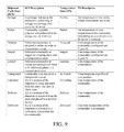
- FIG. 9 is a table that illustrates sequential shipment cycle “states” for temperature controlled commodities within the storage, transportation and delivery segment, according to an embodiment.
- FIG. 10 is a pictorial diagram illustrating an exemplary embodiment in which the logic within the temperature sensor, intelligent devices, database & network and order/commodity planning information operate in concert to automatically “self-assign” states locally and in the network to all areas of the shipment cycle.
- Independent and automatic time-temperature monitoring of commodities taken from shipping pallets is ideally done by the insertion of a sensing probe all the way into the heart of the shipping pallet. This is difficult to implement in practice because pallets are typically built up without a mechanism of inserting temperature probes to their cores.
- An alternative is to sense the temperature of the outer layer of the pallet, and assume that the core is at a similar temperature. Risks in putting any probe directly in the pallet include that it will be forgotten during loading or unloading of the pallet and will get damaged or lost. Therefore, it is common practice to mount independent temperature probes to the walls of the trailers or containers close to the pallets whose time-temperature profiles are desired to be monitored.
- thermocouples or resistance (RTD) elements.
- the actual sensing elements are of low thermal mass and therefore typically respond within milliseconds or seconds to the air temperature around them.
- RTD resistance
- the transported commodity for which they are providing time-temperature monitoring in real time may have a thermal time constant measured in hours. Short term changes in ambient temperature, such as occur when opening and closing doors, may have little impact on the core temperature of a pallet.
- FIG. 1 is a schematic representation of a system for time-temperature monitoring of transportable goods, according to an embodiment.
- a refrigerated asset e.g., container, trailer, railcar, or truck
- a refrigeration unit RU 1 which serves to keep the temperature within the refrigerated asset at a specified set point temperature via the use of controlling temperature sensors mounted within the asset.
- the asset is monitored via an intelligent monitoring device, represented by MD 1 , which may contain several sensors, including GPS, refrigeration asset fuel sensor, door sensor, etc., and may contain a communication system to deliver wireless information (e.g., via satellite, cellular, or short range data communication) to a database and network in real time.
- the intelligent monitoring device MD 1 may be an electronic device, and may include a computing processor and memory.
- a communication path of the intelligent monitoring device MD 1 's communication system may be two-way, allowing commands and instructions to be remotely delivered to the intelligent monitoring device MD 1 .
- the exemplary asset are several pallets 11 containing lading 7 whose temperature needs to be monitored. As illustrated in FIG. 1 , two of the pallets 11 are equipped with temperature probes TP 1 and TP 2 . These may transmit their readings to the intelligent monitoring device unit either via wireless short range communications or via wired harness. Alternatively, the temperature probes may include a data storage system that stores data and may include data memories which can be interrogated at a later date. Also shown in FIG. 1 is a wall-mounted temperature probe TP 3 . This too may be wired or wireless, or may contain data memory which can be interrogated at a later date. Probe TP 3 is inserted into a vial of a material such as ethylene glycol 10 so as to better approximate the thermal response of the nearby
- FIG. 2 illustrates a simple system model of dynamics of temperature change of an object in response to a change in the air temperature constructed of cascading resistances and capacitances, according to an embodiment.
- the dynamics of temperature change of an object in response to a change in the air temperature in which it is placed are governed by the object's thermal mass or capacity (e.g., Joules/Kelvin or Watt-seconds/Kelvin) and its thermal resistance (e.g., Kelvin/watt).
- a system may be modeled by its electrical analog as illustrated in FIG. 2 , which yields the same differential equations. In such an electrical analog model, thermal mass is modeled by capacitance, thermal resistance is modeled by resistance, temperature is modeled by voltage, and heat flow is modeled by current.
- the ambient temperature is modeled by voltage source T a ; the thermal resistance by resistor R T , the thermal mass by capacitor C T .
- the temperature of the core is modeled by voltage T L .
- More complex systems may be modeled by more complex configurations of the components shown.
- T is the temperature T L of the mass
- T 0 is the ambient temperature
- t is time
- R is the thermal resistance R T
- C thermal mass C T .
- a thermal system within a refrigerated transportation asset, and external to the refrigerated transportation asset may be modeled by a temperature probe equipped with a digital filter.
- a wireless electronic temperature probe over a temperature probe immersed in ethylene glycol.
- a given vial of ethylene glycol will at best approximate a single thermal system; with a digital filter, various parameters may be easily altered, both locally and remotely, to model the thermal characteristic of different types of commodities.
- the amount of the commodity placed in the asset may also be taken into consideration regarding its thermal impact and time-temperature profile.
- FIG. 3 illustrates a system for time-temperature monitoring of transportable goods using a temperature probe equipped with a digital filter, according to an embodiment.
- the temperature probe is shown at TP 1 .
- This may be of any design, including but not limited to thermocouple, semiconductor or RTD.
- An analog to digital converter is shown at AD 1 , connected to the temperature probe by link 16 .
- This may be a wired or wireless link. This should not be construed as limiting, as the A/D converter may be physically located with the temperature sensor.
- One or more digital filters are shown at DF, connected to the A/D converter by links 19 , which may be wired or wireless.
- FIG. 4 illustrates a simple digital filter whose time response approximates that of the circuit shown in FIG. 2 , according to an embodiment.
- the new sample S 1 is multiplied by a fixed constant m in multiplier M 1 .
- the current value of the output accumulator OA 1 is multiplied by a fixed constant n.
- the two products are summed together in adder A 1 .
- the result is multiplied by the inverse of the sum of the two multiplicands m and n. This value becomes the new value of the output accumulator OA 1 .
- Delay D 1 is inserted to ensure that the loop iterates once per sample period.
- the exemplary filter simulates a resistor-capacitor network having a time constant of 8 times the sample rate. More complex networks may be modeled by any number of digital filter implementations that will be known to one skilled in the art.
- FIG. 5 illustrates a general time-temperature monitoring system for a storage facility and refrigerated asset, according to an embodiment.
- FIG. 5 shows a storage facility A, with a loading dock A, and three refrigerated assets (X, Y and Z).
- the concept of FIG. 5 illustrates food or drug commodities being removed from Storage Facility A and Loaded into Refrigerated Transport Assets for dispatch to multiple delivery locations, although FIG. 5 may be generalized to illustrate a commodity processor or commodity producer (as opposed to a storage facility). Further, FIG. 5 may be generalized to illustrate refrigerated assets making deliveries to an operator of the commodities, where the processes described herein may be performed in reverse order.
- the refrigerated assets are equipped with intelligent monitoring devices MD 1 , MD 2 , and MD 3 which actively monitor activity and send and receive regular wireless communications to and from a Database and Network A.
- the intelligent monitoring devices are the principle method of delivering time-temperature monitoring data in real time to the network, so that instant or real-time corrective action may be taken for non-compliant conditions.
- the database and network also serves as the primary repository for shipment cycle data proving compliance or certification and responding to audits.
- wireless temperature probes with digital filters, TPA, TPB, TPC, TPD, and TPE, configured to monitor the core temperatures of the commodities and that monitor the commodities in various stages of shipment.
- the relationship of the wireless temperature probes to the commodities within the facility and refrigerated assets, and the refrigerated assets, allow for the overall objective of delivering accurate, real-time time-temperature monitoring data to the database and network to be achieved.
- Wireless temperature probe TPA monitors the time-temperature of the pallets of commodities loaded into asset X.
- wireless probe TPA is configured to simulate the commodities' thermal mass and resistance collectively within asset TPA.
- a remotely configurable digital filter setting is delivered via wireless communication from Database and Network DBA to Intelligent Device MD 1 .
- Intelligent Device MD 1 is in wireless communications with Wireless Temperature probe TPA and changes its parameters to the proper conditions for the load.
- Wireless Temperature probe TPA within asset X may suitably deliver time-temperature monitoring data to the network in real time, for the duration of the shipment.
- the wireless temperature probe would travel with the commodity pallet to retain time-temperature monitoring during the transition from the transportation asset to delivery into the facility.
- Wireless temperature probe TPB is associated with refrigerated asset Z and intelligent device MD 3 via local intelligence on the intelligent device MD 3 .
- the wireless temperature probe TPB has a rechargeable power source, and it may be recharged with refrigerated asset power supplied by the intelligent device MD 3 as well as the refrigerated asset Z's power source.
- the intelligent device MD 3 and the temperature probe TPB establish a logical association to each other, and the probe TPB may be placed in a standard storage holder.
- the intelligent device MD 3 is configurable so that in certain modes of operation, the temperature probe TPB may be installed in the refrigerated asset holder. In this mode, should empty or loaded transport of the asset Z occur without the probe, then the intelligent device MD 3 will send an alarm notification to the database and network DBNA, which may instantly notify the proper operational personnel.
- FIG. 5 also illustrates wireless temperature probe TPC, which is installed on a commodity within a pallet prepared for shipment.
- the temperature probe TPC is in constant communication with intelligent wireless device MD 2 mounted on refrigerated asset Y.
- intelligent wireless device MD 2 mounted on refrigerated asset Y.
- Temperature Probe TPC delivers time-temperature data to the network while constantly monitoring the temperature of the commodity.
- Temperature Probe TPC may receive commodity time-temperature characteristics and the volume data of the commodity shipment from the Database & Network DBNA. Also by virtue of its two-way interface with intelligent device MD 2 , the Temperature Probe TPC may receive a corrected time stamp update based on the GPS sensor configured on intelligent device MD 2 , and the Temperature Probe TPC uses the revised time stamp to record time-temperature data on a continuous basis thereafter once it is no longer associated with intelligent device MD 2 .
- the order for the commodity has recently been associated with refrigerated asset Y, meaning that the transportation segment of the commodity's delivery has been defined by the storage facility personnel.
- the order-asset association for the commodity may be transferred and/or stored in the Database & Network DBNA. Then, the commodity type temperature characteristics and volume may be delivered via wireless communications to the Temperature Probe TPC via intelligent device MD 2 .
- any number of refrigerated assets may interface to any number of wireless temperature sensors. Therefore, to accommodate the proper commodity in the shipment, wireless temperature sensors may be associated via intelligent devices to asset identification numbers. Methods of associating the wireless temperature probe to the proper intelligent device associated with specific refrigerated assets are illustrated in FIG. 7 and are discussed subsequently.
- workers on the loading dock have selected refrigerated asset Y for the shipment of the commodity.
- the workers would have access to specific order information associated with the commodity, and the commodity and packaging would be identified by various electronic tags and bar codes.
- the ability of the local operator or worker to configure into the Wireless Temperature Sensor the proper commodity temperature characteristics and volume via the use of bar codes and shipping information is illustrated in FIG. 8 .
- wireless temperature sensor TPD is attached to a commodity within the processing area/storage area.
- Wireless temperature sensor TPD reads time-temperature data and stores the time-temperature data in its local memory. It is in a self-determined state of monitoring a specific commodity temperature, where the commodity is not associated with a transportation asset yet.
- the temperature sensor TPD has several avenues to communicate to the Database and Network DBNA via intelligent devices MD 1 ,MD 2 , or MD 3 , and the temperature sensor TPD may be placed in a mode to select any path available, but for illustrative purposes of the embodiment of FIG. 5 , Temperature Sensor TPD is in a state where its programming has elected to store time-temperature data.
- time-temperature data may be uploaded for the commodity via the properly selected intelligent device to provide a record of time-temperature data prior to the time of the commodity order or commodity asset assignment transaction.
- Temperature Sensor TPD is ultimately transitioned to a state similar to that of Temperature Sensor TPC, then the time-temperature data of the commodity is linked seamlessly in this transitional part of the shipment cycle.
- Shipment transition state assignments for the wireless Temperature Sensors are illustrated in FIG. 9 and discussed subsequently.
- the Wireless Temperature Sensors TPE actively monitor time-temperature data in electrically powered recharging holders.
- the Wireless Temperature Sensors TPE are powered via rechargeable batteries, and while in fixed site locations, they may be recharged in specially configured fixtures that use electrical power to recharge the Sensor batteries. These power holders are electrically distinguishable from the electrical holders for the Wireless Sensor installed in the transportation assets (e.g., shown for Transportation Asset Z) and connected to intelligent devices.
- the Wireless Temperature Sensors TPE record time-temperature data in real time and transmit the data in real time, along with their state condition illustrated in FIG. 9 , to any available intelligent wireless device in the vicinity (e.g., mounted on transportation assets X, Y, or Z).
- the Wireless Temperature Sensors TPE have “canceled” any commodity temperature characteristic and volume data in their memory and actively monitor air temperature.
- the Database and Network DBNA has real time knowledge of the time-temperature conditions in Storage Facility A.
- FIG. 5 illustrates that a shipment system may be modeled and the time-temperature conditions may be measured for the transition of commodities from a fixed site temperature controlled facility to and from transportation assets accommodating both the thermal characteristic of the commodities and their respective quantity.
- wireless temperature sensors locally knowledgeable of the thermal characteristics of commodities staged for shipment, may be configured via a number of methods suitable for the shipment, providing better representative commodity temperatures throughout the storage and transportation delivery cycle, and in particular during commodity transition conditions between facilities and refrigerated transportation assets.
- the embodiments include the features that the sensor design includes (1) specialized electrical circuitry that may measure core temperatures of commodities relative to air temperature, (2) storage and memory of time-temperature data within the sensor, (3) the ability of the wireless sensor to both transmit data and receive temperature configuration data and GPS time stamp data, and (4) local intelligence of the sensor to automatically determine its “state” within the shipment cycle.
- the illustrated embodiments of FIG. 5 may utilize several additional functions and logic to provide real-time time-temperature data throughout the shipment cycle, including its transition areas. These include:
- the Wireless Temperature Sensor may alter the configuration of its digital filter based on operator input functions that occur locally at the time of commodity order generation or at the time of order assignment to a refrigerated asset. Methods to identify commodity types and volumes associated with shipments are described in FIG. 8 .
- the Wireless Temperature Sensor may have the ability to self-assign shipment cycle “states” to conform to its condition and position within the storage, transportation and delivery shipment cycle as further described in FIG. 9 .
- FIG. 6 illustrates a computer system of the Database and Network DBNA of FIG. 5 , according to an embodiment.
- the computer system may receive input data remotely over wired or wireless communications or input from a user via the control panel/keyboard/monitor/mouse.
- the computer system may output information to the user regarding an operational status of the system using a display panel of the control panel or monitor, or remotely over the wired or wireless communications.
- the computer system may include a processor that performs computations according to program instructions, a memory that stores the computing instructions and other data used or generated by the processor, and a network interface that includes data communications circuitry for interfacing to the wired or wireless communications.
- the wired or wireless communications may include an Ethernet network, asynchronous transfer mode (ATM) network, WiFi network, IEEE-488 interface bus, universal serial bus (USB), RS-232 serial interface, or other communication links and networks as known in the art.
- the network interface may include a network node of the wired or wireless communications or electronics configured to implement protocols of the wired or wireless communications.
- the processor may include a microprocessor, a Field Programmable Gate Array, an Application Specific Integrated Circuit, a custom Very Large Scale Integrated circuit chip, or other electronic circuitry that performs a control function.
- the processor may also include a state machine.
- the computer system may also include one or more electronic circuits and printed circuit boards.
- the processor, memory, and network interface may be coupled with one another using one or more data buses.
- the computer system may communicate with and control various sensors of the system via a control interface.
- the computer system may be controlled by or communicate with a centralized computing system, such as one in a control center of a transportation system operator or manufacturer.
- the computer system may provide system monitoring, remote operation, and data transfer functions.
- the computer system may provide additional communications using an RS-232 communications interface and/or an infrared data port, such as communications with a personal computer (PC).
- Such additional communications may include real-time monitoring of temperature sensors, long-term data retrieval, and system software upgrades.
- the computer system may poll the sensors at a minimum rate such that all time-temperature data required may be obtained by the computer system in time for real-time determination of deviations from pre-determined time-temperature specifications.
- the polled values may be reported by the computer system via the I/O interface and/or the network interface.
- the polled values may also be used in object temperature simulation algorithms by the computer system, and may be stored to long-term memory or a data storage medium for later retrieval and analysis.
- FIG. 7 illustrates three conditions where a Wireless Temperature Sensor may be assigned to logical identifiers at early stages within the storage and transportation shipment cycle, according to an embodiment.
- a wireless temperature sensor identifier is assigned to a refrigerated transportation asset via the use of an intelligent device handheld.
- the intelligent device handhold may be a computing device having features, components, and characteristics similar to that illustrated in FIG. 6 .
- the wireless intelligent devices (MD 1 , MD 2 , and MD 3 ) mounted on the refrigerated assets “seek” temperature sensor identifiers via short range wireless communications (A).
- the intelligent wireless devices Upon discovery or prompting from the intelligent handheld, the intelligent wireless devices transmit their transportation asset ID's (X, Y, and Z) along with the identifiers of temperature sensors (A) in range.
- the wireless temperature sensor (A) “searches” for intelligent devices (MD 1 , MD 2 , and MD 3 ) in range and delivers the available transportation assets (X, Y, and Z) to the intelligent handheld. An operator would then select the designated transportation asset for the identified wireless temperature sensor.
- intelligent devices ( 1 , 2 and 3 ) would assign the refrigerated asset to which they are assigned (X, Y, or Z respectively) a “loaded” or “empty” state, and be available or non-available for selection. This would reduce the volume of traffic and confusion at crowded facilities.
- FIG. 7 addresses a second condition, which may better accommodate the time lags between pulling and palletizing the commodity and assignment to a refrigerated asset.
- the intelligent handheld may receive operator input and association of the wireless temperature sensor and order number (Order ID) of the shipment.
- the intelligent handheld would be configured to allow the operator to select a sensor from those in range (B) and assign it to an order associated with the commodity (F), which is input to the intelligent handheld via manual entry, bar code reading or equivalent or wirelessly if applicable.
- the intelligent handheld receives a wireless list of available assets via the intelligent devices mounted on them (X, Y, or Z) and the operator simply associates the proper order ID to the proper asset.
- the wireless data connection between the sensor (B) and the asset mounted intelligent device is achieved, and the association, time-temperature reading and any stored time-temperature readings are delivered to the Database & Network, associated to both the refrigerated asset and the order number.
- This third condition automatic association of the wireless sensor to a refrigerated asset is illustrated without the aid of an intelligent handheld.
- This third condition illustrates a temperature sensor C installed for some period of time on a commodity for order ID G.
- no intelligent handheld is present and the facility is too crowded with either wireless sensors or intelligent devices in order to make an automatic assignment.
- the placement of the wireless sensor in a rechargeable fixture within the refrigerated asset allows for an automatic association to be achieved.
- the rechargeable fixture has interconnectivity to intelligent device MD 4 .
- the wireless sensor is placed in the fixture, the association between the wireless sensor and the refrigerated asset is completed, allowing for wireless transmission of all historical time-temperature data to the network. Because any pre-set or pre-configured commodity and volume parameters are established on sensor C, placement of the temperature sensor away from the commodity may be safely made without affecting time-temperature data as any susceptibility of the sensor to air temperature is buffered due to its parameter settings.
- disassociation of the asset and the sensor may be performed.
- disassociation of the order and the sensor may be performed.
- FIG. 8 illustrates methods to locally or remotely configure wireless sensors for the type and volume of the commodity they are monitoring for time-temperature data.
- local operators may configure the sensor with the aid of a wireless intelligent handheld, which may receive commodity type and volume data via:
- a software program facilitates the association of commodity types and volume to create and deliver the proper filter parameters to a selected temperature sensor.
- the time-temperature data is adjusted for the commodity's core temperature with respect to its environment.
- the refrigerated asset X via wireless device MD 1 , is associated to the sensor A or order F under the first or second conditions of FIG. 7 .
- temperature sensor B is configured locally via the operator interface with the intelligent handheld and assigned to refrigerated asset Y via intelligent device MD 2 upon placement of the asset-based rechargeable fixture.
- the commodity temperature characteristics are “averaged” for the facility and simulated product temperatures are provided by default parameters. This is electronically similar to providing a temperature sensor in an ethylene glycol solution, adjusted for different facilities.
- order number and commodity type and volume are identified and delivered to a database and network, which automatically delivers the proper commodity parameters to the proper sensor via the intelligent device and order assignment configured via a hand held per FIG. 7 .
- an order ID F associated to a refrigerated asset Z is delivered to intelligent device 3 mounted on asset Z.
- the order association F is found to the intelligent device MD 3 .
- the temperature sensor ID B is identified. Association to intelligent device MD 3 is completed and remote download of parameters to the temperature sensor is initiated.
- the order and asset ID are delivered to Database & Network DBNA, which are remotely delivered via the intelligent device to a temperature sensor inserted or subsequent to the insertion into the rechargeable fixture.
- Order L and transportation asset AA provide the location and commodity type and volume to Database & Network DBNA, which delivers the configuration information to Temperature Sensor C via intelligent wireless device MD 4 .
- FIG. 8 illustrates a method for workers loading the asset with commodities to utilize bar code readers associated with the commodities and their quantities to wirelessly configure the “temperature sensor/digital filter”.
- the order manifest of the order for the transportation asset, containing commodity types and quantities may be received by the wireless network and remotely delivered to the intelligent device, which in turn, configures the temperature sensor/digital filter suitably for the shipment.
- An important implication of this concept is that associated with the commodity core temperatures, commodity prescribed set point temperatures and specific temperature thresholds may be applied to the sensor.
- the Temperature Sensor may record in real time the amount of time a commodity has exceeded a specific temperature harmful to the commodity and also record the time throughout a shipment of the time above a secondary higher threshold. This makes the calculation and detection of food safety problems readily available.
- FIG. 9 illustrates sequential shipment cycle “states” for temperature controlled commodities within the storage, transportation and delivery segment, according to an embodiment.
- the Wireless Temperature Sensor has the ability to “self-assign” shipment cycle states that conform to storage, transportation, delivery and transition activities. These “self-assigned” states are called “temperature states.”
- the objective is to provide temperature visibility end-to-end through all states in real-time so that temperature quality may be assessed instantly at any part of the process with an easily retrievable data record and assigned accountability to parties responsible for each area of the shipment cycle.
- Logic within the wireless device also facilitates the initiation and termination of the shipment cycle for a commodity or palletized commodity.
- the shipment cycle states are not necessarily in sequential order as, particularly with refrigeration assets which support multiple temperature zones, multiple loadings and deliveries of commodities may be made from the same transportation asset.
- FIG. 10 illustrates an exemplary embodiment in which the logic within the temperature sensor, intelligent devices, database & network and order/commodity planning information operate in concert to automatically “self-assign” states locally and in the network to all areas of the shipment cycle.
- the exemplary embodiment uses source information available from multiple sensors simultaneously as well as order and commodity/volume transactions to properly locally “self-assign” temperature states during the shipment cycle.
- Temperature sensors A and B are powered by fixed site fixtures associated with separate production, processing or storage facilities.
- intelligent device MD 1 mounted on transportation asset X is in the proximity of each of the storage facilities of A and B.
- a and B deliver time-temperature data (both real time and stored) to 1 , which communicates the data to Database & Network DBNA.
- the GPS proximity of intelligent device 1 and advance logic applied to it, such as a GPS-based geofence, permits the device and network to identify the facilities. This activity could be accomplished by any number of asset mounted devices installed in the vicinity of A & B.
- a and B are removed from their fixtures and applied to a commodity or pallet being prepared for shipment, and their time-temperature recording is time stamped to initiate a shipment (Pulled State).
- the pallet is identified with an order number (D or E respectively), and the Database & Network DBNA may have access to the order number, the commodity, its shipment volume, its origin and destination locations, responsible party, and other planning elements of the shipment.
- the Database & Network A may be able to make an association regarding an order and staged pallet at each facility, and via wireless communications through intelligent device MD 1 , A and/or B may be transitioned to an Ordered state via MD 1 .
- a pallet or order may be assigned to refrigerated asset X and transferred to Database & Network DBNA.
- intelligent device MD 1 and A and B are assigned to one another, and Temperature Sensors A & B are transitioned to a “Staged” State.
- the sensors within the intelligent device may be utilized to clarify the loading, in-transit and unloading state of Temperature Sensors A & B. For instance, the presence of a Loading geofence within the logic of the intelligent device may allow the Temperature Sensor A or B to be transitioned to a Loading State. Further, specific sensing technology of the Temperature Sensor when it is in the refrigerated asset may allow an automatic transition to Loading State.
- the Temperature Probe B may automatically transition to a Loading State, and when the doors are closed (triggering door sensors) or when the asset moves out of the loading geofence, the Temperature Sensor State may transition to “In-Transit.” Again, it is relevant during these transitional stages to assure that the time-temperature readings are adjusted for the commodity type and volume, as the transition may cause the commodity to be exposed to non-refrigerated conditions for an acceptable or unacceptable time frame.
- the time-temperature information is regularly recorded and delivered to the Database and Network for all Temperature Sensors within the shipment (both Temperature Sensors A and B in this instance). These may be Sensors exposed to the same refrigerated asset set point temperatures or may be applicable to multi-compartment units with different set point temperatures. Most importantly, commodity set point and threshold temperatures may be applied to the commodity via the Database & Network suitable for orders E and F and delivered to the Temperature Sensor. Thus, the Temperature Sensors may record and deliver the time-temperature exposure above or below specific thresholds making food safety conditions visible, or provide insight to induced shelf life problems.
- unloading activities may be detected by the intelligent device causing the Temperature Sensor to transition to an unloading state. This may occur when the asset door is open, may be designated by an unloading geofence within the memory of the intelligent device, or the Temperature Sensor is removed from within the interior of the asset and the intelligent device recognizes it.
- the Temperature state for commodities/sensors that remain with the asset in the transportation cycle such as Temperature Sensor B, which is applied to order E, transition to an unloading state, as Order D with Temperature Sensor A, is removed from the asset.
- Temperature Sensor A Once intelligent device recognizes that the transportation asset has resumed its shipment or is unloaded via internal sensor, geofence, refrigeration unit off, or some combination thereof, it sends a notification to Temperature Sensor A that its delivery state should transition from “unloading” to “delivery.”
- the delivery state remains with the commodity, as Temperature sensor A reads time-temperature data throughout and delivers data via intelligent device MD 1 or some other intelligent device in the proximity.
- Temperature Sensor A is placed in a rechargeable station, and the state is transitioned to “Delivered.” Further, Temperature Sensor A terminates the shipment state, and any commodity type or volume parameters suitable for the journey are cancelled to read time-temperature of ambient air.
- Temperature Sensor B At a different location, Temperature Sensor B is transitioned from an “in-transit” state to “unloading”, “delivery” and “delivered” state in a similar fashion.
- Temperature Sensors integrated with intelligent devices on refrigerated transportation equipment provides advantages not available with prior systems. Significant transition periods occur between refrigerated facilities and refrigerated assets, which often expose food and drugs to unsuitable temperatures.
- the automatic state transitions of the Temperature Sensors allow time-temperature monitoring in real time throughout every phase of the shipment cycle to identify the exposure to unsuitable temperatures as they occur. Further, system flexibility allows the temperature sensors to be automatically configured to monitor core commodity temperatures based on standard type and volume characteristics. Additionally, standard expected set point temperature ranges may be applied to sensors based on the type of commodity or the shipment order. Threshold ranges may be established to allow the wireless temperature sensors to measure the time-temperature exposure of the commodity to unspecified or dangerous temperature levels.
- time-temperature data is provided in real time in suitable formats to avoid spoilage, extend shelf life and eliminate food and drug safety issues.
- the system described herein may comprise a controller including a processor, a memory for storing program data to be executed by the processor, a permanent storage such as a disk drive, a communications port for handling communications with external devices, and user interface devices, including a display, touch panel, keys, buttons, etc.
- these software modules may be stored as program instructions or computer readable code executable by the processor on a non-transitory computer-readable media such as magnetic storage media (e.g., magnetic tapes, hard disks, floppy disks), optical recording media (e.g., CD-ROMs, Digital Versatile Discs (DVDs), etc.), and solid state memory (e.g., random-access memory (RAM), read-only memory (ROM), static random-access memory (SRAM), electrically erasable programmable read-only memory (EEPROM), flash memory, thumb drives, etc.).
- the computer readable recording media may also be distributed over network coupled computer systems so that the computer readable code is stored and executed in a distributed fashion. This computer readable recording media may be read by the computer, stored in the memory, and executed by the processor.
- the invention may be described in terms of functional block components and various processing steps. Such functional blocks may be realized by any number of hardware and/or software components configured to perform the specified functions.
- the invention may employ various integrated circuit components, e.g., memory elements, processing elements, logic elements, look-up tables, and the like, which may carry out a variety of functions under the control of one or more microprocessors or other control devices.
- the elements of the invention are implemented using software programming or software elements
- the invention may be implemented with any programming or scripting language such as C, C++, JAVA®, assembler, or the like, with the various algorithms being implemented with any combination of data structures, objects, processes, routines or other programming elements.
- Functional aspects may be implemented in algorithms that execute on one or more processors.
- the invention may employ any number of conventional techniques for electronics configuration, signal processing and/or control, data processing and the like.
Abstract
Description
-
- Simulated product temperature being conducted electronically, as opposed to using probes immersed in glycol solutions. This provides temperature monitoring of core product temperature without the spiking effects of air temperature.
- The simulated product temperature probe may be either wireless or tethered (e.g., a: re-charged by REEFERTRAK® upon reconnection to a location within each trailer or b: via an independent charging station. REEFERTRAK® is a commercial tracking and real-time monitoring system for refrigerated transportation solutions.)
- The simulated product temperature electronics may be altered via remote communications by identification of the product and its volume. For instance, a certain load size of broccoli would create the calculation of a specific heat calculation, leading to the proper core product vs. air temperature calculation. This could be performed on every load or averaged for shipments which contain mixed amounts of different products.
- The simulated product temperature probe may operate in wireless fashion in the warehouse and yet operate simultaneously as an integrated part of REEFERTRAK® or REEFERTRAK® MARINER when the product is loaded into the refrigerated transportation asset (e.g., refrigerated trailer).
- The probes may be auto registered via the aid of a portable or handheld computing device such as a personal digital assistant (PDA) (e.g., via a search/add function) or bar code reader (associated) to any REEFERTRAK® equipped trailer.
- The probes may be auto registered to an order via a bar code. The order, in turn, may be associated to REEFERTRAK® via dispatch, where the probe-trailer mounted system is associated.
- Trailer association of the load/commodity order at the dock may be used to associate the probe/order to the trailer number.
T=T 0 e −t/RC (1)
-
- The Wireless Temperature Sensor may have the ability to associate/disassociate itself broadly and potentially indirectly to both shipment orders and transportation assets.
- The association with transportation units may be performed by a linkage with a mounted wireless intelligent device with local knowledge of the transportation asset identifier.
- The Temperature Sensor may transmit associated shipment order numbers to the Database & Network through wireless intelligent devices on any or a specific transportation asset.
The association/disassociation function is described inFIG. 7 .
-
- The refrigeration unit is switched off.
- The refrigeration unit is switched off and has entered a specific location entered into the memory of the intelligent device.
- The wireless temperature device is removed from its asset mounted recharging fixture after a settable time period from the commodity loading event or when it was automatically assigned.
- The wireless temperature device is removed from it recharging fixture and the distance between the intelligent device and the temperature sensor is so great as to have the wireless connection broken.
-
- The wireless sensor is removed from its asset mounted rechargeable fixture.
- The wireless sensor detects that it has been inserted into a facility mounted rechargeable fixture.
- The wireless temperature device is removed from it recharging fixture and the distance between the associated intelligent device and the temperature sensor is so great as to have the wireless connection broken.
-
- Barcodes identifying the commodity attached or associated to the commodity or pallet.
- Order numbers associated with the commodity.
- A local database accessible to the operator and or handheld via wireless communications.
- 5 refrigerated asset (e.g., container, trailer, railcar, or truck)
- 7 lading
- 10 ethylene glycol
- 11 pallets
- 16 link
- 19 link
- A loading dock, storage facility
- A1 adder
- AD1 A/D converter
- D1 delay
- DBNA database and network
- M1 multiplier
- MD1 intelligent monitoring device
- OA1 output accumulator
- RU1 refrigeration unit
- S1 sample
- TPx temperature probe/temperature sensor
- X, Y, refrigerated assets
- Z
Claims (7)
Priority Applications (1)
| Application Number | Priority Date | Filing Date | Title |
|---|---|---|---|
| US14/076,904 US9846086B1 (en) | 2012-11-09 | 2013-11-11 | System and method for time-temperature monitoring of transportable goods |
Applications Claiming Priority (2)
| Application Number | Priority Date | Filing Date | Title |
|---|---|---|---|
| US201261724671P | 2012-11-09 | 2012-11-09 | |
| US14/076,904 US9846086B1 (en) | 2012-11-09 | 2013-11-11 | System and method for time-temperature monitoring of transportable goods |
Related Parent Applications (1)
| Application Number | Title | Priority Date | Filing Date |
|---|---|---|---|
| US201261724671P Continuation | 2012-11-09 | 2012-11-09 |
Publications (1)
| Publication Number | Publication Date |
|---|---|
| US9846086B1 true US9846086B1 (en) | 2017-12-19 |
Family
ID=60629019
Family Applications (1)
| Application Number | Title | Priority Date | Filing Date |
|---|---|---|---|
| US14/076,904 Active 2033-11-14 US9846086B1 (en) | 2012-11-09 | 2013-11-11 | System and method for time-temperature monitoring of transportable goods |
Country Status (1)
| Country | Link |
|---|---|
| US (1) | US9846086B1 (en) |
Cited By (40)
| Publication number | Priority date | Publication date | Assignee | Title |
|---|---|---|---|---|
| US20160260058A1 (en) * | 2015-03-02 | 2016-09-08 | Locus Solutions, Llc | Systems and methods for monitoring transported cargo |
| US20190250653A1 (en) * | 2018-02-12 | 2019-08-15 | Overhaul Group, Inc. | Monitoring and ensuring proper ambient conditions, including chemical balance, within a shipping medium used for transporting ambient-condition sensitive goods |
| US20190277558A1 (en) * | 2016-10-12 | 2019-09-12 | Carrier Corporation | Coordination of refrigerated storage containers |
| JP2019172268A (en) * | 2018-03-26 | 2019-10-10 | 東芝Itコントロールシステム株式会社 | Monitoring apparatus |
| US10467579B1 (en) | 2015-03-20 | 2019-11-05 | Square, Inc. | Systems, method, and computer-readable media for estimating timing for delivery orders |
| US10520368B2 (en) * | 2016-11-16 | 2019-12-31 | Fujitsu Limited | Electronic apparatus and surface temperature estimation method therefor |
| US10586273B1 (en) | 2015-07-30 | 2020-03-10 | DoorDash, Inc. | Managing couriers for fast deliveries |
| US10783480B1 (en) * | 2015-03-20 | 2020-09-22 | DoorDash, Inc. | Variable delivery zones for delivery orders |
| US10870333B2 (en) | 2018-10-31 | 2020-12-22 | Thermo King Corporation | Reconfigurable utility power input with passive voltage booster |
| US10875497B2 (en) | 2018-10-31 | 2020-12-29 | Thermo King Corporation | Drive off protection system and method for preventing drive off |
| US10885479B1 (en) | 2015-02-19 | 2021-01-05 | DoorDash, Inc. | Courier network management |
| US10929802B2 (en) * | 2018-03-21 | 2021-02-23 | Deutsche Post Ag | Method for opening a door of a delivery van |
| US10926610B2 (en) | 2018-10-31 | 2021-02-23 | Thermo King Corporation | Methods and systems for controlling a mild hybrid system that powers a transport climate control system |
| US20210101745A1 (en) * | 2019-10-03 | 2021-04-08 | Walmart Apollo, Llc | Temperature-controlled receiving tunnel |
| US10977751B1 (en) | 2015-10-29 | 2021-04-13 | DoorDash, Inc. | Managing communications for combined orders |
| US10985511B2 (en) | 2019-09-09 | 2021-04-20 | Thermo King Corporation | Optimized power cord for transferring power to a transport climate control system |
| US11022451B2 (en) | 2018-11-01 | 2021-06-01 | Thermo King Corporation | Methods and systems for generation and utilization of supplemental stored energy for use in transport climate control |
| US11034213B2 (en) | 2018-09-29 | 2021-06-15 | Thermo King Corporation | Methods and systems for monitoring and displaying energy use and energy cost of a transport vehicle climate control system or a fleet of transport vehicle climate control systems |
| US11059352B2 (en) | 2018-10-31 | 2021-07-13 | Thermo King Corporation | Methods and systems for augmenting a vehicle powered transport climate control system |
| US20210215419A1 (en) * | 2017-07-20 | 2021-07-15 | Guido Dalmolin | System, Method, and Apparatus for Monitoring Refrigeration Units |
| US11072321B2 (en) | 2018-12-31 | 2021-07-27 | Thermo King Corporation | Systems and methods for smart load shedding of a transport vehicle while in transit |
| US11135894B2 (en) | 2019-09-09 | 2021-10-05 | Thermo King Corporation | System and method for managing power and efficiently sourcing a variable voltage for a transport climate control system |
| US20210341340A1 (en) * | 2020-05-04 | 2021-11-04 | Carrier Corporation | System and method for monitoring a container environment |
| US11188970B1 (en) | 2018-09-13 | 2021-11-30 | DoorDash, Inc. | Food delivery optimization |
| US11192451B2 (en) | 2018-09-19 | 2021-12-07 | Thermo King Corporation | Methods and systems for energy management of a transport climate control system |
| US11203262B2 (en) | 2019-09-09 | 2021-12-21 | Thermo King Corporation | Transport climate control system with an accessory power distribution unit for managing transport climate control loads |
| US11205212B1 (en) | 2019-05-08 | 2021-12-21 | DoorDash, Inc. | Integration of functionality of a fulfillment service provider into third-party application |
| US11214118B2 (en) | 2019-09-09 | 2022-01-04 | Thermo King Corporation | Demand-side power distribution management for a plurality of transport climate control systems |
| US11260723B2 (en) | 2018-09-19 | 2022-03-01 | Thermo King Corporation | Methods and systems for power and load management of a transport climate control system |
| US11273684B2 (en) * | 2018-09-29 | 2022-03-15 | Thermo King Corporation | Methods and systems for autonomous climate control optimization of a transport vehicle |
| US11376922B2 (en) | 2019-09-09 | 2022-07-05 | Thermo King Corporation | Transport climate control system with a self-configuring matrix power converter |
| US11420495B2 (en) | 2019-09-09 | 2022-08-23 | Thermo King Corporation | Interface system for connecting a vehicle and a transport climate control system |
| US11458802B2 (en) | 2019-09-09 | 2022-10-04 | Thermo King Corporation | Optimized power management for a transport climate control energy source |
| US20220341658A1 (en) * | 2019-09-30 | 2022-10-27 | Basf Se | System for evaluating the insulation properties of a thermally insulated transport unit |
| US11489431B2 (en) | 2019-12-30 | 2022-11-01 | Thermo King Corporation | Transport climate control system power architecture |
| US11554638B2 (en) | 2018-12-28 | 2023-01-17 | Thermo King Llc | Methods and systems for preserving autonomous operation of a transport climate control system |
| US11595894B2 (en) | 2019-09-20 | 2023-02-28 | Carrier Corporation | Method and system for saving power of a battery associated with item/s |
| US11667165B1 (en) * | 2020-09-29 | 2023-06-06 | Orbcomm Inc. | System, method and apparatus for multi-zone container monitoring |
| US11695275B2 (en) | 2019-09-09 | 2023-07-04 | Thermo King Llc | Prioritized power delivery for facilitating transport climate control |
| US11794551B2 (en) | 2019-09-09 | 2023-10-24 | Thermo King Llc | Optimized power distribution to transport climate control systems amongst one or more electric supply equipment stations |
Citations (7)
| Publication number | Priority date | Publication date | Assignee | Title |
|---|---|---|---|---|
| US5262758A (en) * | 1991-09-19 | 1993-11-16 | Nam Young K | System and method for monitoring temperature |
| US20060224349A1 (en) * | 2005-04-01 | 2006-10-05 | Butterfield Robert D | Temperature prediction system and method |
| US7396157B2 (en) * | 2006-07-14 | 2008-07-08 | Chi-Hong Liao | Body temperature measuring system capable of measuring plural remote temperatures and receiver capable of measuring a body temperature |
| US20090228155A1 (en) * | 2007-11-23 | 2009-09-10 | Slifkin Timothy P | Display and management of events in transport refrigeration units |
| US8390464B1 (en) | 2007-10-11 | 2013-03-05 | Startrak Information Technologies, Llc | Integrating refrigerated transport operations and logistics by creating operational states via wireless communications |
| US20150233847A1 (en) * | 2011-07-18 | 2015-08-20 | Lettuce Box, Llc | Temperature mimic probe for food products |
| US9470587B1 (en) * | 2013-08-16 | 2016-10-18 | Cooper-Atkins Corporation | Solid thermal simulator sensing device |
-
2013
- 2013-11-11 US US14/076,904 patent/US9846086B1/en active Active
Patent Citations (7)
| Publication number | Priority date | Publication date | Assignee | Title |
|---|---|---|---|---|
| US5262758A (en) * | 1991-09-19 | 1993-11-16 | Nam Young K | System and method for monitoring temperature |
| US20060224349A1 (en) * | 2005-04-01 | 2006-10-05 | Butterfield Robert D | Temperature prediction system and method |
| US7396157B2 (en) * | 2006-07-14 | 2008-07-08 | Chi-Hong Liao | Body temperature measuring system capable of measuring plural remote temperatures and receiver capable of measuring a body temperature |
| US8390464B1 (en) | 2007-10-11 | 2013-03-05 | Startrak Information Technologies, Llc | Integrating refrigerated transport operations and logistics by creating operational states via wireless communications |
| US20090228155A1 (en) * | 2007-11-23 | 2009-09-10 | Slifkin Timothy P | Display and management of events in transport refrigeration units |
| US20150233847A1 (en) * | 2011-07-18 | 2015-08-20 | Lettuce Box, Llc | Temperature mimic probe for food products |
| US9470587B1 (en) * | 2013-08-16 | 2016-10-18 | Cooper-Atkins Corporation | Solid thermal simulator sensing device |
Cited By (52)
| Publication number | Priority date | Publication date | Assignee | Title |
|---|---|---|---|---|
| US11915170B2 (en) | 2015-02-19 | 2024-02-27 | DoorDash, Inc. | Delivery agent network management |
| US11429907B2 (en) | 2015-02-19 | 2022-08-30 | DoorDash, Inc. | Courier network management |
| US10885479B1 (en) | 2015-02-19 | 2021-01-05 | DoorDash, Inc. | Courier network management |
| US20160260058A1 (en) * | 2015-03-02 | 2016-09-08 | Locus Solutions, Llc | Systems and methods for monitoring transported cargo |
| US11475391B2 (en) | 2015-03-02 | 2022-10-18 | Locus Solutions, Llc | Systems and methods for monitoring transported cargo |
| US10748109B2 (en) * | 2015-03-02 | 2020-08-18 | Locus Solutions, Llc | Systems and methods for monitoring transported cargo |
| US10467579B1 (en) | 2015-03-20 | 2019-11-05 | Square, Inc. | Systems, method, and computer-readable media for estimating timing for delivery orders |
| US10783480B1 (en) * | 2015-03-20 | 2020-09-22 | DoorDash, Inc. | Variable delivery zones for delivery orders |
| US10586273B1 (en) | 2015-07-30 | 2020-03-10 | DoorDash, Inc. | Managing couriers for fast deliveries |
| US11908026B2 (en) | 2015-10-29 | 2024-02-20 | DoorDash, Inc. | Determining user interface information based on location information |
| US10977751B1 (en) | 2015-10-29 | 2021-04-13 | DoorDash, Inc. | Managing communications for combined orders |
| US20190277558A1 (en) * | 2016-10-12 | 2019-09-12 | Carrier Corporation | Coordination of refrigerated storage containers |
| US11841182B2 (en) * | 2016-10-12 | 2023-12-12 | Carrier Corporation | Coordination of refrigerated storage containers |
| US10520368B2 (en) * | 2016-11-16 | 2019-12-31 | Fujitsu Limited | Electronic apparatus and surface temperature estimation method therefor |
| US11725877B2 (en) * | 2017-07-20 | 2023-08-15 | Guido Dalmolin | System, method, and apparatus for monitoring refrigeration units |
| US20210215419A1 (en) * | 2017-07-20 | 2021-07-15 | Guido Dalmolin | System, Method, and Apparatus for Monitoring Refrigeration Units |
| US10962995B2 (en) * | 2018-02-12 | 2021-03-30 | Overhaul Group, Inc. | Monitoring and ensuring proper ambient conditions, including chemical balance, within a shipping medium used for transporting ambient-condition sensitive goods |
| US20190250653A1 (en) * | 2018-02-12 | 2019-08-15 | Overhaul Group, Inc. | Monitoring and ensuring proper ambient conditions, including chemical balance, within a shipping medium used for transporting ambient-condition sensitive goods |
| US10929802B2 (en) * | 2018-03-21 | 2021-02-23 | Deutsche Post Ag | Method for opening a door of a delivery van |
| JP2019172268A (en) * | 2018-03-26 | 2019-10-10 | 東芝Itコントロールシステム株式会社 | Monitoring apparatus |
| US11188970B1 (en) | 2018-09-13 | 2021-11-30 | DoorDash, Inc. | Food delivery optimization |
| US11192451B2 (en) | 2018-09-19 | 2021-12-07 | Thermo King Corporation | Methods and systems for energy management of a transport climate control system |
| US11260723B2 (en) | 2018-09-19 | 2022-03-01 | Thermo King Corporation | Methods and systems for power and load management of a transport climate control system |
| US11034213B2 (en) | 2018-09-29 | 2021-06-15 | Thermo King Corporation | Methods and systems for monitoring and displaying energy use and energy cost of a transport vehicle climate control system or a fleet of transport vehicle climate control systems |
| US11273684B2 (en) * | 2018-09-29 | 2022-03-15 | Thermo King Corporation | Methods and systems for autonomous climate control optimization of a transport vehicle |
| US10870333B2 (en) | 2018-10-31 | 2020-12-22 | Thermo King Corporation | Reconfigurable utility power input with passive voltage booster |
| US10875497B2 (en) | 2018-10-31 | 2020-12-29 | Thermo King Corporation | Drive off protection system and method for preventing drive off |
| US11059352B2 (en) | 2018-10-31 | 2021-07-13 | Thermo King Corporation | Methods and systems for augmenting a vehicle powered transport climate control system |
| US10926610B2 (en) | 2018-10-31 | 2021-02-23 | Thermo King Corporation | Methods and systems for controlling a mild hybrid system that powers a transport climate control system |
| US11022451B2 (en) | 2018-11-01 | 2021-06-01 | Thermo King Corporation | Methods and systems for generation and utilization of supplemental stored energy for use in transport climate control |
| US11554638B2 (en) | 2018-12-28 | 2023-01-17 | Thermo King Llc | Methods and systems for preserving autonomous operation of a transport climate control system |
| US11884258B2 (en) | 2018-12-31 | 2024-01-30 | Thermo King Llc | Systems and methods for smart load shedding of a transport vehicle while in transit |
| US11072321B2 (en) | 2018-12-31 | 2021-07-27 | Thermo King Corporation | Systems and methods for smart load shedding of a transport vehicle while in transit |
| US11205212B1 (en) | 2019-05-08 | 2021-12-21 | DoorDash, Inc. | Integration of functionality of a fulfillment service provider into third-party application |
| US10985511B2 (en) | 2019-09-09 | 2021-04-20 | Thermo King Corporation | Optimized power cord for transferring power to a transport climate control system |
| US11712943B2 (en) | 2019-09-09 | 2023-08-01 | Thermo King Llc | System and method for managing power and efficiently sourcing a variable voltage for a transport climate control system |
| US11420495B2 (en) | 2019-09-09 | 2022-08-23 | Thermo King Corporation | Interface system for connecting a vehicle and a transport climate control system |
| US11135894B2 (en) | 2019-09-09 | 2021-10-05 | Thermo King Corporation | System and method for managing power and efficiently sourcing a variable voltage for a transport climate control system |
| US11203262B2 (en) | 2019-09-09 | 2021-12-21 | Thermo King Corporation | Transport climate control system with an accessory power distribution unit for managing transport climate control loads |
| US11376922B2 (en) | 2019-09-09 | 2022-07-05 | Thermo King Corporation | Transport climate control system with a self-configuring matrix power converter |
| US11214118B2 (en) | 2019-09-09 | 2022-01-04 | Thermo King Corporation | Demand-side power distribution management for a plurality of transport climate control systems |
| US11827106B2 (en) | 2019-09-09 | 2023-11-28 | Thermo King Llc | Transport climate control system with an accessory power distribution unit for managing transport climate control loads |
| US11695275B2 (en) | 2019-09-09 | 2023-07-04 | Thermo King Llc | Prioritized power delivery for facilitating transport climate control |
| US11458802B2 (en) | 2019-09-09 | 2022-10-04 | Thermo King Corporation | Optimized power management for a transport climate control energy source |
| US11794551B2 (en) | 2019-09-09 | 2023-10-24 | Thermo King Llc | Optimized power distribution to transport climate control systems amongst one or more electric supply equipment stations |
| US11595894B2 (en) | 2019-09-20 | 2023-02-28 | Carrier Corporation | Method and system for saving power of a battery associated with item/s |
| US20220341658A1 (en) * | 2019-09-30 | 2022-10-27 | Basf Se | System for evaluating the insulation properties of a thermally insulated transport unit |
| US20210101745A1 (en) * | 2019-10-03 | 2021-04-08 | Walmart Apollo, Llc | Temperature-controlled receiving tunnel |
| US11843303B2 (en) | 2019-12-30 | 2023-12-12 | Thermo King Llc | Transport climate control system power architecture |
| US11489431B2 (en) | 2019-12-30 | 2022-11-01 | Thermo King Corporation | Transport climate control system power architecture |
| US20210341340A1 (en) * | 2020-05-04 | 2021-11-04 | Carrier Corporation | System and method for monitoring a container environment |
| US11667165B1 (en) * | 2020-09-29 | 2023-06-06 | Orbcomm Inc. | System, method and apparatus for multi-zone container monitoring |
Similar Documents
| Publication | Publication Date | Title |
|---|---|---|
| US9846086B1 (en) | System and method for time-temperature monitoring of transportable goods | |
| US20230281487A1 (en) | Inference electronic shelf life dating system for perishables | |
| EP3504491B1 (en) | A system comprising a plurality of refrigeration units | |
| JP7047013B2 (en) | Intelligent routing code to improve product distribution | |
| US10877013B2 (en) | System, method, and apparatus for condition monitoring of food and other perishable products as well as environmentally sensitive industrial supply chains | |
| US7545267B2 (en) | Arrangement and method for product information interaction with building control system elements | |
| Jedermann et al. | Semi-passive RFID and beyond: steps towards automated quality tracing in the food chain | |
| US10242338B2 (en) | Systems and methods for managing an inventory of products purchased by customers from a retailer | |
| US11468755B2 (en) | Systems and methods for monitoring, tracking and tracing logistics | |
| US20110022532A1 (en) | Systems and methods for tracking an object in transit | |
| US10342737B1 (en) | Active monitoring system for thermally-managed transportation and storage of specific perishable products | |
| JP2005071295A (en) | Information processing apparatus and method, and vehicle | |
| KR20170020155A (en) | Reader logger and delivery information management system for collecting and record the delivery environment information and location information | |
| WO2001048623A1 (en) | Food safety control method and apparatus | |
| US10817825B2 (en) | Remote integration of cloud services and transportable perishable products active monitor | |
| JP6431434B2 (en) | Temperature management device and temperature management system | |
| US20230288265A1 (en) | Method for monitoring temperature of product deliveries from origin to destination | |
| JP2008037536A (en) | Environment recording device | |
| EP3997643A2 (en) | Remote integration of cloud services and transportable perishable products active monitor | |
| TW201637957A (en) | Device for monitoring shipped article and method thereof | |
| JP2004257655A (en) | Information management system, distribution system, information acquiring device, and information management device |
Legal Events
| Date | Code | Title | Description |
|---|---|---|---|
| AS | Assignment |
Owner name: MACQUARIE CAF LLC, NEW YORK Free format text: SECURITY INTEREST;ASSIGNORS:ORBCOMM INC.;ORBCOMM LLC;ORBCOMM LICENSE CORP.;AND OTHERS;REEL/FRAME:034012/0341 Effective date: 20141010 |
|
| AS | Assignment |
Owner name: STARTRAK INFORMATION TECHNOLOGIES, LLC, NEW JERSEY Free format text: ASSIGNMENT OF ASSIGNORS INTEREST;ASSIGNORS:PERTEN, HERBERT;ROBINSON, THOMAS A.;GSELL, DAVID;SIGNING DATES FROM 20140930 TO 20160825;REEL/FRAME:040451/0947 |
|
| AS | Assignment |
Owner name: AMERISCAN, INC., MARYLAND Free format text: RELEASE BY SECURED PARTY;ASSIGNOR:MACQUARIE CAF LLC;REEL/FRAME:042201/0798 Effective date: 20170410 Owner name: ORBCOMM INC., NEW JERSEY Free format text: RELEASE BY SECURED PARTY;ASSIGNOR:MACQUARIE CAF LLC;REEL/FRAME:042201/0798 Effective date: 20170410 Owner name: ORBCOMM INTERNATIONAL HOLDINGS 3 LLC, NEW JERSEY Free format text: RELEASE BY SECURED PARTY;ASSIGNOR:MACQUARIE CAF LLC;REEL/FRAME:042201/0798 Effective date: 20170410 Owner name: ORBCOMM AFRICA LLC, NEW JERSEY Free format text: RELEASE BY SECURED PARTY;ASSIGNOR:MACQUARIE CAF LLC;REEL/FRAME:042201/0798 Effective date: 20170410 Owner name: ORBCOMM INDIA LLC, NEW JERSEY Free format text: RELEASE BY SECURED PARTY;ASSIGNOR:MACQUARIE CAF LLC;REEL/FRAME:042201/0798 Effective date: 20170410 Owner name: STARTRAK LOGISTICS MANAGEMENT SOLUTIONS, LLC, NEW Free format text: RELEASE BY SECURED PARTY;ASSIGNOR:MACQUARIE CAF LLC;REEL/FRAME:042201/0798 Effective date: 20170410 Owner name: ORBCOMM INTERNATIONAL HOLDINGS 1 LLC, NEW JERSEY Free format text: RELEASE BY SECURED PARTY;ASSIGNOR:MACQUARIE CAF LLC;REEL/FRAME:042201/0798 Effective date: 20170410 Owner name: ORBCOMM SOUTH AFRICA GATEWAY COMPANY LLC, NEW JERS Free format text: RELEASE BY SECURED PARTY;ASSIGNOR:MACQUARIE CAF LLC;REEL/FRAME:042201/0798 Effective date: 20170410 Owner name: GLOBALTRAK, LLC, NEW JERSEY Free format text: RELEASE BY SECURED PARTY;ASSIGNOR:MACQUARIE CAF LLC;REEL/FRAME:042201/0798 Effective date: 20170410 Owner name: ORBCOMM SENS, LLC, NEW JERSEY Free format text: RELEASE BY SECURED PARTY;ASSIGNOR:MACQUARIE CAF LLC;REEL/FRAME:042201/0798 Effective date: 20170410 Owner name: ORBCOMM INTERNATIONAL HOLDINGS LLC, NEW JERSEY Free format text: RELEASE BY SECURED PARTY;ASSIGNOR:MACQUARIE CAF LLC;REEL/FRAME:042201/0798 Effective date: 20170410 Owner name: ORBCOMM AIS LLC, NEW JERSEY Free format text: RELEASE BY SECURED PARTY;ASSIGNOR:MACQUARIE CAF LLC;REEL/FRAME:042201/0798 Effective date: 20170410 Owner name: RIDGELEY HOLDINGS, LLC, NEW JERSEY Free format text: RELEASE BY SECURED PARTY;ASSIGNOR:MACQUARIE CAF LLC;REEL/FRAME:042201/0798 Effective date: 20170410 Owner name: ORBCOMM CENTRAL AMERICA HOLDINGS LLC, NEW JERSEY Free format text: RELEASE BY SECURED PARTY;ASSIGNOR:MACQUARIE CAF LLC;REEL/FRAME:042201/0798 Effective date: 20170410 Owner name: STARTRAK INFORMATION TECHNOLOGIES, LLC, NEW JERSEY Free format text: RELEASE BY SECURED PARTY;ASSIGNOR:MACQUARIE CAF LLC;REEL/FRAME:042201/0798 Effective date: 20170410 Owner name: ORBCOMM CHINA LLC, NEW JERSEY Free format text: RELEASE BY SECURED PARTY;ASSIGNOR:MACQUARIE CAF LLC;REEL/FRAME:042201/0798 Effective date: 20170410 Owner name: ORBCOMM TERRESTRIAL LLC, NEW JERSEY Free format text: RELEASE BY SECURED PARTY;ASSIGNOR:MACQUARIE CAF LLC;REEL/FRAME:042201/0798 Effective date: 20170410 Owner name: MOBILENET, LLC, NEW JERSEY Free format text: RELEASE BY SECURED PARTY;ASSIGNOR:MACQUARIE CAF LLC;REEL/FRAME:042201/0798 Effective date: 20170410 Owner name: ORBCOMM INTERNATIONAL HOLDINGS 2 LLC, NEW JERSEY Free format text: RELEASE BY SECURED PARTY;ASSIGNOR:MACQUARIE CAF LLC;REEL/FRAME:042201/0798 Effective date: 20170410 Owner name: ORBCOMM LICENSE CORP., NEW JERSEY Free format text: RELEASE BY SECURED PARTY;ASSIGNOR:MACQUARIE CAF LLC;REEL/FRAME:042201/0798 Effective date: 20170410 Owner name: ORBCOMM CIS LLC, NEW JERSEY Free format text: RELEASE BY SECURED PARTY;ASSIGNOR:MACQUARIE CAF LLC;REEL/FRAME:042201/0798 Effective date: 20170410 Owner name: ORBCOMM LLC, NEW JERSEY Free format text: RELEASE BY SECURED PARTY;ASSIGNOR:MACQUARIE CAF LLC;REEL/FRAME:042201/0798 Effective date: 20170410 |
|
| AS | Assignment |
Owner name: U.S. BANK NATIONAL ASSOCIATION, AS COLLATERAL AGEN Free format text: SECURITY AGREEMENT;ASSIGNORS:ORBCOMM INC.;ORBCOMM LLC;STARTRAK INFORMATION TECHNOLOGIES, LLC;AND OTHERS;REEL/FRAME:042809/0437 Effective date: 20170410 |
|
| STCF | Information on status: patent grant |
Free format text: PATENTED CASE |
|
| AS | Assignment |
Owner name: JPMORGAN CHASE BANK, N.A., AS COLLATERAL AGENT FOR Free format text: SECURITY INTEREST;ASSIGNORS:ORBCOMM INC.;ORBCOMM LLC;STARTRAK INFORMATION TECHNOLOGIES, LLC;AND OTHERS;REEL/FRAME:044908/0688 Effective date: 20171218 |
|
| MAFP | Maintenance fee payment |
Free format text: PAYMENT OF MAINTENANCE FEE, 4TH YEAR, LARGE ENTITY (ORIGINAL EVENT CODE: M1551); ENTITY STATUS OF PATENT OWNER: LARGE ENTITY Year of fee payment: 4 |
|
| AS | Assignment |
Owner name: CREDIT SUISSE AG, CAYMAN ISLANDS BRANCH, AS COLLATERAL AGENT, NEW YORK Free format text: FIRST LIEN PATENT SECURITY AGREEMENT;ASSIGNOR:STARTRAK INFORMATION TECHNOLOGIES, LLC;REEL/FRAME:057394/0050 Effective date: 20210901 Owner name: WAM SOLUTIONS LLC, NEW JERSEY Free format text: RELEASE BY SECURED PARTY;ASSIGNOR:JPMORGAN CHASE BANK, N.A.;REEL/FRAME:057392/0596 Effective date: 20210901 Owner name: STARTRAK INFORMATION TECHNOLOGIES, LLC, NEW JERSEY Free format text: RELEASE BY SECURED PARTY;ASSIGNOR:JPMORGAN CHASE BANK, N.A.;REEL/FRAME:057392/0596 Effective date: 20210901 Owner name: STARTRAK LOGISTICS MANAGEMENT SOLUTIONS, LLC, NEW JERSEY Free format text: RELEASE BY SECURED PARTY;ASSIGNOR:JPMORGAN CHASE BANK, N.A.;REEL/FRAME:057392/0596 Effective date: 20210901 Owner name: INTHINC LLC, NEW JERSEY Free format text: RELEASE BY SECURED PARTY;ASSIGNOR:JPMORGAN CHASE BANK, N.A.;REEL/FRAME:057392/0596 Effective date: 20210901 Owner name: INSYNC SOFTWARE, INC., NEW JERSEY Free format text: RELEASE BY SECURED PARTY;ASSIGNOR:JPMORGAN CHASE BANK, N.A.;REEL/FRAME:057392/0596 Effective date: 20210901 Owner name: GLOBALTRAK, LLC, NEW JERSEY Free format text: RELEASE BY SECURED PARTY;ASSIGNOR:JPMORGAN CHASE BANK, N.A.;REEL/FRAME:057392/0596 Effective date: 20210901 Owner name: ORBCOMM LLC, NEW JERSEY Free format text: RELEASE BY SECURED PARTY;ASSIGNOR:JPMORGAN CHASE BANK, N.A.;REEL/FRAME:057392/0596 Effective date: 20210901 Owner name: ORBCOMM INC., NEW JERSEY Free format text: RELEASE BY SECURED PARTY;ASSIGNOR:JPMORGAN CHASE BANK, N.A.;REEL/FRAME:057392/0596 Effective date: 20210901 |