EP2689705B1 - Système pour commander la fermeture d'une porte d'appareil électroménager, en particulier pour une machine à laver, telle qu'un lave-vaisselle - Google Patents
Système pour commander la fermeture d'une porte d'appareil électroménager, en particulier pour une machine à laver, telle qu'un lave-vaisselle Download PDFInfo
- Publication number
- EP2689705B1 EP2689705B1 EP13176820.2A EP13176820A EP2689705B1 EP 2689705 B1 EP2689705 B1 EP 2689705B1 EP 13176820 A EP13176820 A EP 13176820A EP 2689705 B1 EP2689705 B1 EP 2689705B1
- Authority
- EP
- European Patent Office
- Prior art keywords
- striker
- condition
- thrust member
- door
- locking mechanism
- Prior art date
- Legal status (The legal status is an assumption and is not a legal conclusion. Google has not performed a legal analysis and makes no representation as to the accuracy of the status listed.)
- Active
Links
- 238000005406 washing Methods 0.000 title claims description 12
- 230000007246 mechanism Effects 0.000 claims description 81
- 230000000694 effects Effects 0.000 claims description 8
- 238000004891 communication Methods 0.000 claims description 7
- 230000009471 action Effects 0.000 description 29
- 230000008878 coupling Effects 0.000 description 9
- 238000010168 coupling process Methods 0.000 description 9
- 238000005859 coupling reaction Methods 0.000 description 9
- 210000003128 head Anatomy 0.000 description 8
- 230000006835 compression Effects 0.000 description 4
- 238000007906 compression Methods 0.000 description 4
- 230000000295 complement effect Effects 0.000 description 3
- 230000002093 peripheral effect Effects 0.000 description 3
- 230000036316 preload Effects 0.000 description 3
- 230000008901 benefit Effects 0.000 description 2
- 238000001816 cooling Methods 0.000 description 2
- 230000001419 dependent effect Effects 0.000 description 2
- 238000006073 displacement reaction Methods 0.000 description 2
- 238000001035 drying Methods 0.000 description 2
- 238000000605 extraction Methods 0.000 description 2
- 230000006870 function Effects 0.000 description 2
- 238000001746 injection moulding Methods 0.000 description 2
- 230000000670 limiting effect Effects 0.000 description 2
- 239000000463 material Substances 0.000 description 2
- 238000000034 method Methods 0.000 description 2
- 210000001331 nose Anatomy 0.000 description 2
- 230000036961 partial effect Effects 0.000 description 2
- 230000008569 process Effects 0.000 description 2
- 238000007789 sealing Methods 0.000 description 2
- 229910001285 shape-memory alloy Inorganic materials 0.000 description 2
- 230000003213 activating effect Effects 0.000 description 1
- 238000005452 bending Methods 0.000 description 1
- 230000009194 climbing Effects 0.000 description 1
- 238000010438 heat treatment Methods 0.000 description 1
- 230000002401 inhibitory effect Effects 0.000 description 1
- 238000009434 installation Methods 0.000 description 1
- 230000002452 interceptive effect Effects 0.000 description 1
- 230000010355 oscillation Effects 0.000 description 1
- 238000013021 overheating Methods 0.000 description 1
- 230000000284 resting effect Effects 0.000 description 1
- 238000004804 winding Methods 0.000 description 1
Images


Classifications
-
- A—HUMAN NECESSITIES
- A47—FURNITURE; DOMESTIC ARTICLES OR APPLIANCES; COFFEE MILLS; SPICE MILLS; SUCTION CLEANERS IN GENERAL
- A47L—DOMESTIC WASHING OR CLEANING; SUCTION CLEANERS IN GENERAL
- A47L15/00—Washing or rinsing machines for crockery or tableware
- A47L15/42—Details
- A47L15/48—Drying arrangements
- A47L15/488—Connections of the tub with the ambient air, e.g. air intake or venting arrangements
-
- A—HUMAN NECESSITIES
- A47—FURNITURE; DOMESTIC ARTICLES OR APPLIANCES; COFFEE MILLS; SPICE MILLS; SUCTION CLEANERS IN GENERAL
- A47L—DOMESTIC WASHING OR CLEANING; SUCTION CLEANERS IN GENERAL
- A47L15/00—Washing or rinsing machines for crockery or tableware
- A47L15/0018—Controlling processes, i.e. processes to control the operation of the machine characterised by the purpose or target of the control
- A47L15/0021—Regulation of operational steps within the washing processes, e.g. optimisation or improvement of operational steps depending from the detergent nature or from the condition of the crockery
- A47L15/0034—Drying phases, including dripping-off phases
-
- A—HUMAN NECESSITIES
- A47—FURNITURE; DOMESTIC ARTICLES OR APPLIANCES; COFFEE MILLS; SPICE MILLS; SUCTION CLEANERS IN GENERAL
- A47L—DOMESTIC WASHING OR CLEANING; SUCTION CLEANERS IN GENERAL
- A47L15/00—Washing or rinsing machines for crockery or tableware
- A47L15/42—Details
- A47L15/4251—Details of the casing
- A47L15/4257—Details of the loading door
- A47L15/4259—Arrangements of locking or security/safety devices for doors, e.g. door latches, switch to stop operation when door is open
-
- E—FIXED CONSTRUCTIONS
- E05—LOCKS; KEYS; WINDOW OR DOOR FITTINGS; SAFES
- E05B—LOCKS; ACCESSORIES THEREFOR; HANDCUFFS
- E05B17/00—Accessories in connection with locks
- E05B17/0025—Devices for forcing the wing firmly against its seat or to initiate the opening of the wing
- E05B17/0033—Devices for forcing the wing firmly against its seat or to initiate the opening of the wing for opening only
- E05B17/0037—Spring-operated
-
- E—FIXED CONSTRUCTIONS
- E05—LOCKS; KEYS; WINDOW OR DOOR FITTINGS; SAFES
- E05B—LOCKS; ACCESSORIES THEREFOR; HANDCUFFS
- E05B47/00—Operating or controlling locks or other fastening devices by electric or magnetic means
- E05B47/0001—Operating or controlling locks or other fastening devices by electric or magnetic means with electric actuators; Constructional features thereof
- E05B47/0009—Operating or controlling locks or other fastening devices by electric or magnetic means with electric actuators; Constructional features thereof with thermo-electric actuators, e.g. heated bimetals
-
- E—FIXED CONSTRUCTIONS
- E05—LOCKS; KEYS; WINDOW OR DOOR FITTINGS; SAFES
- E05B—LOCKS; ACCESSORIES THEREFOR; HANDCUFFS
- E05B63/00—Locks or fastenings with special structural characteristics
- E05B63/24—Arrangements in which the fastening members which engage one another are mounted respectively on the wing and the frame and are both movable, e.g. for release by moving either of them
-
- A—HUMAN NECESSITIES
- A47—FURNITURE; DOMESTIC ARTICLES OR APPLIANCES; COFFEE MILLS; SPICE MILLS; SUCTION CLEANERS IN GENERAL
- A47L—DOMESTIC WASHING OR CLEANING; SUCTION CLEANERS IN GENERAL
- A47L2401/00—Automatic detection in controlling methods of washing or rinsing machines for crockery or tableware, e.g. information provided by sensors entered into controlling devices
- A47L2401/20—Time, e.g. elapsed operating time
-
- A—HUMAN NECESSITIES
- A47—FURNITURE; DOMESTIC ARTICLES OR APPLIANCES; COFFEE MILLS; SPICE MILLS; SUCTION CLEANERS IN GENERAL
- A47L—DOMESTIC WASHING OR CLEANING; SUCTION CLEANERS IN GENERAL
- A47L2501/00—Output in controlling method of washing or rinsing machines for crockery or tableware, i.e. quantities or components controlled, or actions performed by the controlling device executing the controlling method
- A47L2501/22—Loading doors, e.g. door latches, inflatable door seals
-
- E—FIXED CONSTRUCTIONS
- E05—LOCKS; KEYS; WINDOW OR DOOR FITTINGS; SAFES
- E05C—BOLTS OR FASTENING DEVICES FOR WINGS, SPECIALLY FOR DOORS OR WINDOWS
- E05C17/00—Devices for holding wings open; Devices for limiting opening of wings or for holding wings open by a movable member extending between frame and wing; Braking devices, stops or buffers, combined therewith
- E05C17/56—Devices for holding wings open; Devices for limiting opening of wings or for holding wings open by a movable member extending between frame and wing; Braking devices, stops or buffers, combined therewith by magnetic or electromagnetic attraction or operated by electric or electromagnetic means
-
- E—FIXED CONSTRUCTIONS
- E05—LOCKS; KEYS; WINDOW OR DOOR FITTINGS; SAFES
- E05Y—INDEXING SCHEME ASSOCIATED WITH SUBCLASSES E05D AND E05F, RELATING TO CONSTRUCTION ELEMENTS, ELECTRIC CONTROL, POWER SUPPLY, POWER SIGNAL OR TRANSMISSION, USER INTERFACES, MOUNTING OR COUPLING, DETAILS, ACCESSORIES, AUXILIARY OPERATIONS NOT OTHERWISE PROVIDED FOR, APPLICATION THEREOF
- E05Y2201/00—Constructional elements; Accessories therefor
- E05Y2201/40—Motors; Magnets; Springs; Weights; Accessories therefor
- E05Y2201/404—Function thereof
- E05Y2201/422—Function thereof for opening
- E05Y2201/426—Function thereof for opening for the initial opening movement
-
- E—FIXED CONSTRUCTIONS
- E05—LOCKS; KEYS; WINDOW OR DOOR FITTINGS; SAFES
- E05Y—INDEXING SCHEME ASSOCIATED WITH SUBCLASSES E05D AND E05F, RELATING TO CONSTRUCTION ELEMENTS, ELECTRIC CONTROL, POWER SUPPLY, POWER SIGNAL OR TRANSMISSION, USER INTERFACES, MOUNTING OR COUPLING, DETAILS, ACCESSORIES, AUXILIARY OPERATIONS NOT OTHERWISE PROVIDED FOR, APPLICATION THEREOF
- E05Y2900/00—Application of doors, windows, wings or fittings thereof
- E05Y2900/30—Application of doors, windows, wings or fittings thereof for domestic appliances
- E05Y2900/304—Application of doors, windows, wings or fittings thereof for domestic appliances for dishwashers
Definitions
- the present invention relates to a system for controlling the closing of a door of a household appliance, in particular for a washing machine, such as a dishwasher.
- a door is employed which is movable relative to the cabinet in a manner such as to open or close an access opening, through which the inner chamber can communicate with the environment outside the household appliance.
- such systems comprise an engagement element mounted on either one of said cabinet or said door, and a retaining element mounted on the other one of the door and the cabinet.
- the retaining element is adapted to releasably retain the engagement element, so as to constrain the door to the cabinet when the household appliance is in use.
- the coupling between the engagement element and the retaining element is typically accomplished by a user, who causes them to abut against each other by manually pushing the door against the cabinet until it fully closes.
- the decoupling between the engagement element and the retaining element is also accomplished by the user, who operates suitable control interfaces (e.g. provided on the front wall of the door or on the front or top face of the cabinet) to activate internal mechanisms of the retaining element in order to disengage the engagement element from the retaining element.
- WO 2009/146874 A1 discloses a dishwasher having a rinsing container that can be closed by a pivoting door, wherein to provide locking a locking device disposed on the door engages into a clamp disposed on the rinsing container, and wherein to open the door in gaps the clamp is disposed on an adjustable connecting rod that is adjustable in the opening direction by means of a drive.
- the invention provides means for returning the clamp at least approximately to the initial position thereof opposite to the opening direction as a result of the further opening movement of the door.
- WO 2011/141542 A1 discloses a dishwasher comprising a body, a door which provides access into the body and opens from the top downwards by rotating around the horizontal axis, a door latch which provides the door to be locked, and a door opening mechanism having a linear actuator that provides the door to be opened automatically at the end of the washing and drying processes such that some gap remains between the door and the body.
- This device proves to be particularly advantageous in washing machines, e.g. dishwashers, because it allows the steam generated during the wash cycle to escape into the outside environment, thereby contributing to at least partially drying the items contained in the wash chamber.
- W designates as a whole one example of a washing machine subject to installation of a first and, respectively, a second exemplary embodiments of a system 10, 110 according to the present invention.
- the washing machine is a dishwasher W yet, as will become apparent from the present description, system 10, 110 may also be applied to different washing machines or to other household appliances.
- dishwasher W has a cabinet C in which a wash tub or chamber WT is defined, which is adapted to receive the crockery to be washed.
- Wash tub WT has an access opening O, through which it communicates with the outside environment and can therefore receive the crockery.
- dishwasher W has a door D adapted to open ( Figure 1 ) and close ( Figure 2 ) access opening O.
- Access opening O is provided on a front face of cabinet C and, preferably, door D is tiltably mounted relative to cabinet C, e.g. being hinged under the latter to a horizontal axis.
- access opening O has a peripheral sealing gasket SG that allows wash tub WT to be closed fluid-tight when door D is in a fully closed condition.
- cabinet C has a lid L, which is advantageously situated on the top of said cabinet C.
- washing machine W is shown only partially without lid L which is typically present on the top of cabinet C.
- Machine W preferably has a crossbar CB situated on a wall of wash tub WT.
- the system is adapted to allow closing door D of dishwasher W, and comprises an engagement element 11 to be mounted on cabinet C, e.g. to crossbar CB positioned between cabinet C and lid L.
- Engagement element 11 is adapted to be releasably held by a retaining element 16 to be mounted on door D, e.g. on the rear face thereof facing towards access opening O.
- Retaining element 16 is adapted to releasably retain engagement element 11, so as to constrain door D to cabinet C when dishwasher W is in use.
- engagement element 11 is mounted on cabinet C and retaining element 16 is mounded on door D.
- Engagement element 11 comprises a supporting body 12 which, in the illustrated embodiments, is secured to cabinet C, and a striker 14 associated with supporting body 12 and adapted to be releasably coupled to retaining element 16 mounted on door D, so as to constrain door D to cabinet C when dishwasher W is in use.
- supporting body 12 is designed as an internally hollow casing, e.g. including a pair of half-shells or trays 12a, 12b, which are snap coupled together at their periphery.
- half-shells 12a, 12b of supporting body 12 are made of plastic material, e.g. by injection moulding.
- supporting body 12 is screwed to cabinet C of household appliance W, e.g. at crossbar CB.
- striker 14 is movably mounted relative to supporting body 12 between a retracted position ( Figures 2 , 3 , 5 and 7 ) and an extracted position ( Figure 6 ).
- the movement of striker 14 is guided by supporting body 12, particularly by inner walls of the latter.
- striker 14 is slideable relative to supporting body 12.
- striker 14 is made of plastic material, e.g. by injection moulding.
- striker 14 in the retracted position striker 14 partially protrudes from supporting body 12, whereas in the extracted position striker 14 protrudes further out by an additional section.
- striker 14 protrudes through a slot (not numbered) provided on the front face of cabinet C of dishwasher W whereto the whole engagement element 11 has been mounted.
- Retaining element 16 is substantially of a per se known type, e.g. with a slotted container body housing an engagement mechanism to which striker 14 can gain access through the slot in order to be releasably coupled to said engagement mechanism.
- said engagement mechanism can oscillate between a working position and an idle position, and comprises a swivelling member, the movement of which is countered by an elastic member, and with which the striker 14 is adapted to releasably engage.
- the revolving member of the engagement mechanism holds striker 14 when door D is closed.
- the revolving member of the engagement mechanism releases striker 14 when the user operates a suitable release mechanism (not shown), e.g. including a push-button, a lever or a knob, located on door D.
- retaining element 16 Some examples of such a retaining element 16 are widely known in the industry and have been described in detail in many prior-art documents. For completeness' sake, Italian patent applications no. T097A1120 , T02000A000383 and T02001A01003 can be mentioned in this regard, the contents of which is to be understood as incorporated herein by way of reference and example. For brevity, therefore, retaining element 16 will not be described any further herein.
- striker 14 when striker 14 is coupled to retaining element 16 and moves into the extracted position, it allows retaining element 16 to be moved away from supporting body 12, resulting in door D moving away from cabinet C. Due to the coupling between striker 14 and retaining element 16, door D will remain constrained to cabinet C without however closing access opening O fluid-tight.
- engagement element 11 further comprises a locking mechanism, designated as a whole 18.
- locking mechanism 18 is mounted on supporting body 12; in particular, it is contained in the cavity defined by supporting body 12 itself.
- locking mechanism 18 tends to switch from an unlocking condition ( Figure 6 ), in which it is adapted to allow releasing striker 14, allowing the latter to move from the retracted position to the extracted position when striker 14 is coupled to retaining element 16, to a locking condition ( Figures 3 , 5 , 7 ), in which it is adapted to allow holding striker 14 when striker 14 is in the retracted position.
- engagement element 11 comprises electrically controlled actuator means 20 adapted to control the switching of locking mechanism 18 from the locking condition to the unlocking condition. For example, said switching occurs when actuator 20 is energized by an electric current flowing therethrough.
- actuator 20 is connected to an external control unit associated with the household appliance W and capable of supplying electric current to actuator 20 in predetermined conditions of use.
- actuator means 20 are mounted on supporting body 12, e.g. housed in the cavity defined within the latter.
- engagement element 11 further comprises return means 15 adapted to optionally return striker 14 into the retracted position when said striker 14 is decoupled from retaining element 16.
- return means 15 are mounted on supporting body 12. This prevents striker 14 from protruding excessively - possibly jeopardizing the users' safety - from cabinet C of dishwasher W when a user decouples striker 14 from retaining element 16 by operating suitable release mechanisms provided on dishwasher W to move door D from the pre-open condition to the fully open condition.
- the return means comprise elastic return means, e.g. comprising a return spring 15.
- elastic return means 15 are adapted to operate by traction.
- System 10 further comprises a thrust member 19 capable of exerting a thrust on door D in the direction of movement of striker 14 from the retracted position to the extracted position, thus facilitating the switching of door D into the pre-open condition when striker 14 is coupled to retaining element 16 and locking mechanism 18 is in the unlocking condition. In this manner, the switching of door D from the fully closed condition to the pre-open condition is made easier and more reliable.
- the use of thrust member 19 makes it possible to optionally adopt return means 15 associated with striker 14.
- return means 15 associated with striker 14.
- the movement of striker 14 from the retracted position to the extracted position takes place against the action of return means 15.
- the action of return means 15 may tendentially be promoted by the weight of door D (which is connected to striker 14 via the coupling with retaining element 16) and, possibly, by the elastic compression load exerted by gasket SG compressed between door D and cabinet C, it may however risk to be significantly hindered or even prevented by return means 15.
- the action of return means 15 can be effectively countered because thrust member 19 prevents return means 15 from keeping door D from oscillating when locking mechanism 18 switches to the unlocking condition.
- return means 15 are present, the return force exerted by them is advantageously smaller than the thrust force exerted by thrust member 19.
- Engagement element 11 preferably includes said thrust member 19, e.g. substantially elongated in shape, which is movably mounted relative to supporting body 12 so as to exert said thrust, thus switching from a retracted condition to an extracted condition. This allows to obtain a compact configuration of system 10 by integrating thrust member 19 into the structure of engagement element 11.
- thrust member 19 protrudes from supporting body 12 in the retracted condition only a small section (or none at all) of thrust member 19 protrudes from supporting body 12, whereas in the extracted condition thrust member 19 protrudes further out by an additional length.
- thrust member 19 is housed within the supporting body 12 and slides relative to the latter, e.g. being guided by inner walls of said supporting body 12.
- engagement element 11 further comprises elastic stressing means 21 acting upon thrust member 19 and tending to bring it into the extracted condition.
- system 10 further comprises elastic stressing means 21 acting upon said thrust member 19 and tending to bring it into the extracted condition.
- elastic stressing means 21 are mounted between supporting body 12 and thrust member 19, and are adapted, for example, to operate by traction, pulling thrust member 19 outwards from the supporting body.
- the elastic stressing means comprise at least one traction spring 21; in the illustrated embodiments a pair of traction springs 21 are employed.
- striker 14 and thrust member 19 are movable in parallel directions.
- striker 14 and thrust member 19 are mounted to each other in a mutually guided manner, particularly in a slideable fashion.
- striker 14 and thrust member 19 are mutually integral with each other while sliding from the respective retracted position or condition to the respective extracted position or condition, when striker 14 is coupled to said retaining element 16 and locking mechanism 18 releases at least one of striker 14 and thrust member 19, thereby switching from the locking condition to the unlocking condition.
- This is particularly useful to avoid that, while striker 14 is moving from the retracted position to the extracted position, thrust member 19 and door D (the position of which depends on the position of striker 14 because of the connection still existing between engagement element 11 and retaining element 16) might get into mutual positions not allowing a correct thrust action towards the pre-open position.
- thrust member 14 is made slidable as a unit with striker 19 by striker 14 resting on thrust member 19.
- striker 14 can slide relative to thrust member 19 along at least a part of the travel from the extracted position to the retracted position, under the control of said return means 15, when striker 14 and the retaining element are decoupled.
- striker 14 is slideable from the extracted position to the retracted position independently of the movement of thrust member 19.
- proximal slide 14a has a transversal extension 14a in which proximal slide 19a is slideably mounted, advantageously in a "drawer-like" fashion, in the axial direction between the retracted condition and the extracted condition of thrust member 19.
- transversal extension 14b has suitable slots 14c extending in the axial direction, within which complementary protrusions can slide, e.g. pegs 19c, carried by proximal slide 19a.
- striker 14 and thrust member 19 have reciprocal distal appendices 14d and 19d mounted on proximal slides 14a and 19a and adapted to protrude outwards from supporting body 12 (through front slots or apertures formed in the latter), so as to cooperate with said retaining element 16 and said door D.
- each distal appendix 14d and 19d has a pair of connection legs which can be elastically stretched apart and coupled by interference into suitable slots (not numbered, but distinctly visible in Figure 4a ) formed at the front in proximal slides 14a and 19a.
- proximal portions 14a and 14b are advantageously always contained within the housing defined by supporting body 12, without protruding externally thereto during the movement of striker 14 and of thrust member 19.
- return spring 15 which advantageously operates by traction, is mounted between a peg 14e carried by striker 14, in particular by proximal slide 14a, and a respective peg 12e carried by supporting body 12.
- each stressing spring 21, which advantageously operates by traction, is mounted between a respective peg 19f carried by proximal slide 19a and a respective peg 12f carried by supporting body 12.
- the force exerted by it on striker 14 is advantageously smaller than the force exerted by stressing springs 21 on thrust member 19.
- the respective proximal portions 14a and 19a have respective shoulders 14g and 19g adapted to abut against each other while switching from the respective retracted position or condition to the respective extracted position or condition.
- shoulder 14g is adapted to abut against shoulder 19g in order to keep, when in use, thrust member 19 in abutment with door D, so as to exert an optimal thrust towards the pre-open position.
- the shoulder of striker 14 is defined by an upper corner 14g brought into an axially forward position by transversal extension 14b, whereas the shoulder of thrust member 19 is defined by a tooth 19g protruding upwards from proximal portion 19a in an axially forward position of the latter.
- locking mechanism 18 is adapted to constrain at least one of striker 14 and thrust member 19, thus preventing it from moving to the extracted position and, respectively, to the extracted condition when striker 14 and/or thrust member 19 is in the respective retracted position or condition, and locking mechanism 18 is in the locking condition.
- locking mechanism 18 can be designed with different possible configurations, since it can be structured for:
- locking mechanism 18 is adapted to operate in a transversal direction relative to the direction of movement of striker 14 and/or of thrust member 19.
- locking mechanism 18 is adapted to act upon striker 14, in particular by releasing or holding a transversal protrusion 14h carried by striker 14, e.g. by transversal extension 14b.
- system 10 comprises sensing means 23 adapted to detect the extracted position or condition of at least one of striker 14 and thrust member 19. This allows to obtain an indirect indication about the state of door D in operation.
- the sensing means are adapted to monitor the position of striker 14, and are therefore adapted to provide an indication about the fact that striker 14 is in the extracted position - and hence door D is in the pre-open condition.
- sensing means 23 comprise a mobile element 23a, movable relative to said supporting body 12 in a manner controlled by at least one of striker 14 and thrust member 19, and a sensitive member 23b, which is adapted to provide an indication about the position taken by mobile element 23a.
- mobile element 23a can be moved in a guided manner from supporting body 12, in particular in a transversal direction relative to the direction in which striker 14 or thrust member 19 is adapted to move.
- mobile element 23a is housed within the casing formed by supporting body 12.
- the mobile element is a cursor 23a, which on one side cooperates with striker 14 or with thrust member 19, and on the other side cooperates with sensitive member 23b.
- the sensitive member is a switch 23b, particularly a microswitch, adapted to be operated by mobile element 23a, e.g. by an appendix (not numbered) carried by mobile element 23a and capable of activating switch 23b according to predetermined criteria.
- mobile element 23a is adapted to be pushed in abutment with at least one of striker 14 and thrust member 19 through the effect of elastic countering means 25. More in detail, the action of elastic countering means 25 takes place in a manner such that mobile element 23a is brought from a normally idle condition ( Figures 3 , 5 and 7 ), in which it does not actuate sensitive member 23b when striker 14 and/or the thrust member are in the retracted position or condition, to an active condition ( Figure 6 ), in which it actuates sensitive member 23b when striker 14 and/or thrust member 21 are in the extracted position or condition.
- mobile element 23a is associated and pushed by striker 14, e.g. by transversal protrusion 14h, which tends to push it towards the normally idle condition. When transversal protrusion 14h, while the striker is moving towards the extracted position, goes past mobile element 23a, the latter can move into the active condition.
- mobile element 23a may include a lug 23c, and the supporting body may have a corresponding lug 12c, in turn extending through a slot 23d on mobile element 23a.
- elastic countering means 25 may be mounted, particularly tending to move said lugs 12c and 23c away from each other, thereby causing mobile element 23a to push against striker 14 and/or thrust member 19.
- actuator 20 is adapted to switch from a normally extended condition ( Figures 3 , 5 and 7 ) to a contracted condition ( Figure 6 ). In the extended condition, actuator 20 allows locking mechanism 18 to get into the locking condition; in the contracted condition, instead, actuator 20 brings locking mechanism 18 into the unlocking condition.
- actuator 20 comprises a shape-memory conductive element 22 mechanically connected to and cooperating with the locking mechanism.
- conductive element 22 is made of a shape memory alloy (SMA) capable of taking a preset shape (in this case corresponding to the shape taken in the contracted condition) following a variation in its temperature which is due, in the illustrated embodiments, to heating through the Joule effect caused by current flowing through it.
- SMA shape memory alloy
- conductive element 22 may be replaced with different types of electric actuators; in such variants, the actuator may include an electromagnetic actuator (e.g. of the solenoid type) or an electrothermal actuator (e.g. of the wax type). Said types of actuators are per se known in the art and will not therefore be described for the sake of brevity.
- conductive element 22 is provided in the form of a wire mechanically connected to - and acting upon - locking mechanism 18 in order to bring the latter from the normal locking condition to the unlocking condition.
- conductive element 22 is advantageously connected in series to a positive temperature coefficient (PTC) resistor.
- PTC positive temperature coefficient
- locking mechanism 18 comprises a slide 24 which can move, in particular slide, relative to supporting body 12 from a locking position ( Figures 3 , 5 and 7 ) to an unlocking position ( Figure 6 ).
- slide 24 In the locking position, slide 24 is adapted to hold at least one of striker 14 and thrust member 19 when it is in the retracted position and, respectively, in the retracted condition, thereby preventing it from moving to the extracted position and, respectively, into the extracted condition.
- slide 24 allows the movement of at least one of striker 14 (from the retracted position to the extracted position) and thrust member 19 (from the retracted condition to the extracted condition) through the effect of an electric energization of actuator 20.
- locking mechanism 18 comprises an elastic member 26 tending to hold slide 24 in the locking position.
- elastic member 26 is interposed between supporting body 12 and slide 24.
- elastic member 26 is a spring, e.g. a compression-preloaded spring, advantageously of the coil type.
- slide 24 cooperates with striker 14.
- Slide 24 is preferably positioned against a protrusion formed transversally in at least one of striker 14 and thrust member 19, when slide 24 is in the locking position and striker 14 or the thrust member is in the retracted position or, respectively, in the retracted condition.
- said protrusion advantageously coincides with transversal protrusion 14h of striker 14.
- locking mechanism 18 has a substantially ratchet-like property, wherein slide 24 behaves like a ratchet adapted to prevent the movement of at least one of striker 14 and thrust member 19.
- striker 14 is subject, on one side, to "extraction” forces due to the thrust force exerted by thrust member 19 and to the weight of door D, possibly assisted by the elastic compression of sealing gasket SG.
- striker 14 is subject to "retraction” forces due to the action of return means 15 (if present), which forces are generally smaller than the opening forces. Therefore, when locking mechanism 18 is in the locking condition, slide 24 that constrains striker 14 prevents the "extraction” forces from actuating the system to bring door D into the pre-open condition.
- slide 24 and striker 14 preferably have respective complementary profiles 28 and 30 cooperating with each other.
- Profiles 28 and 30 are adapted to allow, by interference, the forced displacement of striker 14 from the extracted position to the retracted position, possibly with the contribution of return means 15, thus countering the action of elastic member 26.
- return means 15 are present, they are so sized as to exert a return force, e.g. an elastic pulling force, having such intensity as to overcome the elastic countering force exerted by elastic member 26.
- profiles 28 and 30 are respective inclined sections of projecting noses (not numbered) carried by slide 24 and, respectively, by striker 14, in particular by transversal protrusion 14h. The cooperation between profiles 28 and 30 will be described in detail below, jointly with the overall operation of system 10.
- locking mechanism 18 further comprises a cursor 36 movable by means of actuator 20 and movably, in particularly slideably, mounted relative to supporting body 12 from an idle position ( Figure 3 , 5 and 7 ) to an active position ( Figure 6 ).
- cursor 36 In the idle position, cursor 36 allows slide 24 to move from the unlocking position to the locking position under the action of elastic member 26.
- cursor 36 drags slide 24 from the locking position to the unlocking position against the action of elastic member 26 when actuator 20 is electrically energized.
- locking mechanism 18 comprises an elastic element 38 tending to hold cursor 36 in the idle position.
- elastic element 38 is mounted between supporting body 12 and cursor 36.
- elastic element 38 is a spring, e.g. a compression-preloaded spring, advantageously of the coil type.
- cursor 36 is mechanically connected to shape-memory element 22, and is therefore adapted to be dragged by the latter between the idle position and the active position.
- the shape-memory element is provided in the form of a conductive wire 22 connected to cursor 36, e.g. arranged in a U fashion to embrace with its bend a part of cursor 36.
- said conductive wire 22 is wound with its bend along a peripheral section of a prominent portion 39 (which in the illustrated embodiment is a substantially annular portion surrounding an inner cavity into which the elastic element is placed during assembly) of cursor 36, e.g. it is inserted into a perimetric groove (not numbered) formed in said peripheral section.
- slide 24 and cursor 36 are coupled together with some sliding play.
- the coupling between slide 24 and the cursor is substantially of the so-called "coulisse" type.
- cursor 36 has a mushroom-shaped end 40 and slide 24 has a profiled cavity 42 that houses mushroom-shaped end 40 with some axial play.
- mushroom-shaped end 40 has a transversally wider head and a narrower neck which tapers away from the head; in its turn, cavity 42 has a transversally wider proximal portion that houses the head with some axial play, and a transversally narrower distal portion that extends from the proximal portion and allows, through it, the axial sliding of the neck (details not numbered).
- profiled cavity 42 is defined by a pair of side arms 44 situated at the end of slide 24, which converge transversally inwards at their free ends.
- each one of side arms 44 defines a substantially hook-like shape.
- a closing crosspiece (not numbered) is mounted, e.g. by interference fit; this reduces the risk of head 42 undesirably coming out by climbing over side arms 44.
- elastic element 38 exerts an elastic return force on cursor 36 which is greater than the elastic return force exerted by elastic member 26 on slide 24.
- elastic element 38 can effectively return cursor 36 into the active position, in particular by reliably pulling back conductive wire 22 with a high-intensity force.
- elastic member 26 can thus return slide 24 into the locking position, without however hindering - by exerting excessive resistance - the action of return means 15 (if present), which forcedly return the slide 24 into the retracted position when the user causes the decoupling of striker 14 of engagement element 11 from retaining element 16 by operating a suitable release mechanism provided on door D or on cabinet C.
- slide 24 and/or cursor 36 are movable in a direction which is substantially transversal, preferably orthogonal, to the direction of movement of striker 14 and/or of thrust member 19 (if present).
- slide 24 and cursor 36 are movable in the same direction.
- locking mechanism 18 is adapted to stop the electric energization of actuator 20 after locking mechanism 18 has gone into the unlocking condition.
- the actuator 20 comprises a safety switch 45, e.g. a microswitch, controlled by locking mechanism 18 and adapted to electrically disconnect actuator 20 from the external control unit when locking mechanism 18 gets into the unlocking condition.
- switch 45 is electrically connected downstream of one of the power contacts (not numbered) that allow connecting actuator 20 to the external control unit.
- power contacts 46 are electrically connected to the ends of conductive wire 22.
- switch 45 comprises a fixed contact (not numbered) and a mobile contact (not numbered) cooperating with locking mechanism 18 in a manner such that it is moved away from the fixed contact as locking mechanism 18 reaches the unlocking condition.
- the mobile contact has a profiled protrusion adapted to abut against a corresponding protrusion 52 carried by locking mechanism 18, e.g. by cursor 36, so that the mobile contact will detach itself, e.g. by bending, from the fixed contact when locking mechanism 18 reaches the unlocking condition, e.g. when cursor 36 reaches the active position.
- the profiled protrusion of the mobile contact has a cusp-like profile.
- protrusion 52 has an inclined section substantially conjugated to the cusp-profiled section of the mobile contact.
- elastic member 26 is preferably axially interposed between a lug 58 protruding from slide 24 and a fixed shelf 60 protruding from supporting body 12, e.g. from lower half-shell 12b.
- shelf 60 is housed in a guide aperture (not numbered) formed through slide 24. In this manner, elastic member 26 can push lug 58 as a unit with slide 24 until a terminal edge of said guide aperture abuts against fixed shelf 60, which corresponds to the locking position of slide 24. Therefore, fixed shelf 60 also acts as an end-of-travel element for slide 24.
- cursor 36 is slideable in supporting body 12, being preferably guided by inner walls of supporting body 12, e.g. by walls of lower half-shell 12b and by the back walls of both half-shells 12a and 12b.
- elastic element 38 is axially interposed between an additional lug (e.g. prominent portion 39), protruding from cursor 36, and an additional fixed shelf 66, protruding from supporting body 12, e.g. from lower half-shell 12b.
- additional shelf 66 is housed in an additional guide aperture (not numbered) formed through cursor 36, e.g. in the vicinity of the additional lug (through prominent portion 39 in the illustrated embodiments).
- additional fixed shelf 66 also acts as an end-of-travel element for the cursor.
- switches 23b and 45, along with resistor PTC, are carried by a support or board PCB on which a printed circuit is formed which connects said switches and resistor.
- support PCB has two pairs of connection terminals 70 and 72 adapted to supply electric power to actuator means 20 and to sensing means 23, respectively, e.g. via resistor PTC and switch 23b, respectively.
- Such a configuration corresponds, in system 10, to the one shown in Figure 7 , wherein engagement element 11 has striker 14 held in the retracted position by return means 15, locking mechanism 18 is arranged in the locking condition, thrust member 19 is held in the extracted condition by stressing means 21, actuator 20 is not electrically energized, and sensing means 23 detect the retracted position of striker 14. More in detail, slide 24 is held in the locking position by elastic member 26, while cursor 36 is held in the idle position by elastic element 38. Furthermore, conductive wire 22 is in the extended condition and is held in traction. Also, protrusion 14h abuts against slide 24.
- door D can be opened completely by a user, and crockery to be washed can thus be introduced into wash chamber WT.
- the user can afterwards program the wash cycle of dishwasher W by using suitable control interfaces typically provided on door D.
- door D of dishwasher W will be fully closed and engagement element 11 will be in the configuration shown in Figures 2 and 3 , coupled to retaining element 16.
- thrust member 19 - in abutment with door D - exerts its action against door D, but cannot cause it to open because striker 14 behaves like a "dead bolt” holding door D in the closed position.
- striker 14 can translate from the retracted position to the extracted position, it is stopped and firmly held in the retracted position by locking mechanism 18, in particular through the effect of the abutment of slide 24 against striker 14 (e.g. against transversal protrusion 14h).
- engagement element 11 has striker 14 in the retracted position, locking mechanism 18 is in the locking condition, thrust member 19 is in the retracted position, actuator means 20 are not electrically energized, and sensing means 23 detect the retracted position of striker 14. More in detail, slide 24 is held in the locking position by elastic member 26, while cursor 36 is held in the idle position by elastic element 38. Furthermore, conductive wire 22 is in the extended or elongated condition.
- the wash cycle programmed by the user can be automatically activated by the external control unit of dishwasher W.
- the external control unit will send a current impulse to actuator 20, so as to electrically energize it and bring locking mechanism 18 into the unlocking condition.
- conductive wire 22 is designed to reduce its length by approx. 3,5% while switching from the longer extended condition to the shorter contracted condition.
- striker 14 is free to move into the extracted position ( Figure 6 ) through the effect of the connection with retaining element 16, which is carried by door D, with the assistance of the thrust member 19.
- the thrust member 19 contributes to pushing the door D away from the cabinet C against the retaining action of the return means 15, which act upon the striker 14 and tend to hold it in the retracted position.
- the shoulder 14g of the striker 14 advantageously abuts against the shoulder 19g of the thrust member 19, so that the striker 14 and the thrust member 19 are made as a unit with each other while moving towards the respective extracted position or condition.
- the striker 14 and the thrust member 19 are designed to, when they are in the extracted position, protrude further outwards from the supporting body 12 by an extension of a few centimetres (preferably 1 to 3 cm, but in certain conditions of use even more than 5 cm with respect to the normal projection of the striker 14 and of the thrust member 19 when they are in the retracted position or condition); in this way, the movement of the door D away from the access opening O, which is dependent on the above-mentioned extension, will be sufficient to allow the fluidic communication between the wash chamber WT and the environment outside the cabinet C.
- said extension is approx. 5.5 cm.
- the sensing means 23 detect the switching of the striker 14 into the extracted position, which in this case is indicative of the fact that the door D has reached the pre-open position.
- the actuator 20 When the electric current impulse supplied by the external control unit stops, the actuator 20 returns into the electrically de-energized condition and the locking mechanism 18 returns into the locking condition.
- the elastic element 37 has an elastic compression preload of approx. 0.5 kg, and the conductive wire 22 has a diameter of approx. 0.38 mm.
- the preload of the elastic element 38 is adapted to the diameter of the conductive wire 22, in order that the cursor 36 can be effectively returned into the idle position.
- the elastic member 26 has an elastic compression preload of approx. 200 g, which is smaller than that of the elastic element.
- the main function of the elastic member 26 is to prevent the slide 24 from correctly rearranging itself into the locking position, in particular should the return action exerted on the conductive wire 22 by the elastic element 38 cause any accidental jamming or seizure.
- the conductive wire 22 is designed to cool down and go back from the shorter contracted condition to the longer extended condition within approx. 13 sec.
- the locking mechanism 18 when the locking mechanism 18 gets into the unlocking condition, it will stop the electric connection between the external control unit and the actuator 20.
- This measure has been conceived in order to avoid any damage to the conductive wire 22 which might be caused by overheating due to an accidentally excessive duration of the energization current impulse supplied by the external control unit (e.g. caused by said impulse not being interrupted within nominal times). This can be accomplished in different ways.
- a first possible way is to use the safety switch 45. More in detail, when the cursor 36 reaches the active position, it interferes with the safety switch, thus opening it and breaking the current flow through the conductive wire 22. In particular, the protrusion 52 of the cursor 36 rests against the profiled protrusion of the mobile contact of the safety switch 45, thereby moving it away from the associated fixed contact.
- a second possible way is to use the sensing means 23. More in detail, when the mobile element 23a is brought by the striker 14 (in particular, by cooperating with its transversal protrusion 14h) from the normally idle condition to the active condition, the sensitive element 23b detects its displacement and signals it to the external control unit of the dishwasher, e.g. through the contacts 72. In this manner, the external control unit receives the signal coming from the sensitive element 23b and cuts the current flow through the actuator means 20, in particular the conductive wire 22. In the illustrated embodiments, when the mobile element 23a moves into the active condition, the appendix of the latter interacts with the mobile contact of the switch 23b, so that the switch 23b will generate said signal intended for the external control unit.
- the two switches 23b and 45 may possibly cooperate with each other, supplying the signal to the external control unit only if both of them are appropriately operated by the mobile element 23a, in particular by its terminal appendix, and, respectively, by the locking mechanism 18, in particular by the cursor 36 (e.g. by its protrusion 52).
- the switches 23b and 45 are adapted to signal the movement of the striker 14 from the retracted condition to the extracted condition (which in this case is indicative of the switching of the door D into the pre-open condition) when they are both open.
- the door D When the locking mechanism 18 returns into the locking condition and the striker 14 has moved into the extracted condition, the door D is in the pre-open condition, in which it is sufficiently spaced apart from the access opening O to allow the fluidic communication between the wash chamber WT and the outside environment.
- the distance between the door D and the access opening O allows the steam generated by the dishwasher W during a wash cycle to escape, thus allowing the crockery contained in the wash chamber WT to dry.
- the user can decouple the door D from the cabinet C by operating the mechanisms situated on the door D to bring the retaining element 16 into the idle position. In this way, the retaining element 16 and the striker 14 of the engagement element 11 will disengage from each other.
- the return means 15 will no longer meet any opposition while returning the striker 14 into the retracted position, since said striker 14 is not constrained to the door D.
- the return force exerted by the return spring 15 causes the profile 30 carried by the striker 14 (in particular, by the transversal protrusion 14h) to abut against the profile 28, in turn carried by the slide 24, so as to generate a thrust transversal to the striker 14.
- the return spring 15 is sized in a manner such as to generate a transverse thrust capable of moving the slide 24 backwards by overcoming the countering force exerted by the elastic member 26.
- the backward movement of the slide 24 does not interfere with the position of the cursor 36 and therefore the elastic element 38 is not stressed, in particular thanks to the sliding coupling with some play between them. More in detail, the proximal portion of the cavity 42 moves relative to the head of the mushroom-shaped end 40 without them getting into mutual abutment.
- the cooperation between the slide 24 and the cursor 36 offers the advantage of preventing the conductive wire 22, while the striker 14 is switching from the extracted position to the retracted position, from temporarily loosening from the locking mechanism 18, resulting in a malfunctioning or damaged system 10.
- the slide 24 can freely move from the locking position to the unlocking position against the action of the elastic member 26 without interfering with the cursor 36, in particular thanks to the sliding motion with play advantageously allowed between the mushroom-shaped head 40 and the side arms 44. In this manner, the cursor 36 will not be moved backwards and will not loosen the tension of the conductive wire 22, which will always remain under traction.
- the thrust member 19 will be kept in the extracted condition by the elastic stressing means 21, which will meet no opposition by the locking mechanism 18 or by the striker 14. In this first embodiment, therefore, the locking mechanism 18 does not cooperate with or is constrained to the thrust member 19 directly, but via the striker 14.
- the door D can thus be opened further compared to the pre-open configuration, and the washed - and at least partially dried - crockery can be picked up by the user; the process can then be restarted as previous described in order to carry out a new wash cycle.
- the door D can be finally closed by the user, the door abutting against the thrust member 19 and pushing it backwards into the retracted condition, and coupling the striker 14 to the retaining element 16.
- the switching of the thrust member 19 from the extracted condition to the retracted condition is controlled by the backward thrust exerted through the door D as it is pushed shut by the user. Keeping the thrust member 19 in the retracted condition is ensured by the coupling between the striker 14 and the retaining element 16. Said coupling, in fact, holds the door D in abutment with the thrust member 19 through the action of the locking mechanism 18, which prevents the striker 14 from moving relative to the supporting body. This situation corresponds to the operating configuration shown in Figure 5 .
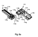
- Figures 8 to 13 show a system 110 designed in accordance with a second embodiment of the present invention.
- Said system 110 is substantially similar to the system 10 designed in accordance with the first embodiment of the present invention. Therefore, details and elements which are similar to - or which perform the same function as - those of the previously illustrated embodiment will be associated with the same alphanumerical references. For brevity, the description of such details and elements will not be repeated below, and reference will be made to the above description of the first embodiment.
- the second embodiment of the system 110 differs from the first embodiment of the system 10 for a few aspects relating to the structure, assembly and cooperation of the striker, designated herein as a whole by numeral 114, and of the thrust member, designated herein as a whole by numeral 119.
- the striker 114 can slide from the extracted position to the retracted position while being constrained - for a part of its travel - to the movement of the thrust member 119.
- the proximal slide 119a has a transversal extension 119b on which the proximal slide 114 is slideably mounted in the axial direction between the retracted position and the extracted position of the striker 114.
- the sliding between the transversal extension 119b and the proximal slide 114a is substantially of the "skid" type, i.e. the top of the proximal slide 114a has a first profile 114c, 114c' extending axially and coupled to a corresponding second profile 119c, 119c' also extending axially and carried under the transversal extension 119b.
- the first profile has a pair of ribs 114c coupled into a cavity 119c of the second profile, and a groove 114c' in turn coupled to a relief 119c' carried by the second profile.
- the optional return spring 15, which advantageously operates by traction, is mounted between a peg 114e carried by the striker 114, in particular by its proximal slide 114a, and a respective peg 119e carried by the thrust member 119, in particular by its transversal extension 119b.
- the peg 119e is carried in a receding channel (not numbered) extending axially on the top of the transversal extension 119b.
- the sensing means 23 are adapted to monitor the position of the thrust member 119, and are therefore adapted to provide an indication about the fact that the thrust member 119 is in the extracted position - and hence that the door D is in the pre-open condition.
- the mobile element 23a is associated with and pushed by the thrust member 119, e.g. by a transversal protrusion 119h thereof, which tends to push the mobile element 23a towards the normally idle condition.
- the transversal protrusion 119h while the thrust member 119h is moving towards the extracted position, goes past the mobile element 23a, the latter can move into the active condition.
- the locking mechanism 18 is adapted to act upon the thrust member 119, in particular releasing or holding the transversal protrusion 119h carried by the thrust member 119, e.g. by the proximal portion 119a.
- the slide 24 cooperates with the thrust member, e.g. with the transversal protrusion 119h.
- the slide 24 and the thrust member 119 preferably have respective complementary profiles 28 and 130 cooperating with each other.
- the profiles 28 and 130 are adapted to allow the thrust member 119 to be forcedly moved, by interference, from the extracted condition to the retracted condition through the action of a user pushing the swivelling door D towards the fully closed configuration.
- the profiles 28 and 130 are respective inclined sections of projecting noses (not numbered) carried by the slide 24 and, respectively, by the thrust member 119, in particular by the transversal protrusion 119h.
- the cooperation between the profiles 28 and 130 takes place in a manner similar to that described for the profiles 28 and 30 of the first embodiment of the system 10, with the difference that in this case such cooperation does not take place automatically through the return means 15, but through the action of a user pushing the swivelling door D into the fully closed configuration.
- the locking mechanism 18 therefore does not cooperate with or is constrained to the striker 114 directly, but via the thrust member 119.
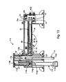
- Such a configuration corresponds, in the system 110, to the one shown in Figure 9 , wherein the locking mechanism 18 is arranged in the locking condition, the thrust member 19 is held in the retracted condition by the locking mechanism 18 against the action of the stressing means 21, the striker 114 is in turn held in the retracted position by the return spring 15 and is also constrained to the thrust member 119 due to the abutment of the shoulder 114g against the shoulder 119g, the actuator member 20 is not electrically energized, and the sensing means 23 detect the retracted position of the thrust member 119. More in detail, the slide 24 is held in the locking position by the elastic member 26, while the cursor 36 is held in the idle position by the elastic element 38. Furthermore, the conductive wire 22 is in the extended condition and is held in traction. Also, the protrusion 119h abuts against the slide 24.
- the door D can be opened completely by a user, and crockery to be washed can thus be introduced into the wash chamber WT.
- the user can afterwards program the wash cycle of the dishwasher W by using suitable control interfaces typically provided on the door D.
- the door D of the dishwasher W will be fully closed and the engagement element 11 will be in the configuration shown in Figure 2 , coupled to the retaining element 16.
- the system 110 will always remain in the same configuration with a fully open door ( Figure 9 ), in that the thrust member 119 will be locked in the retracted condition, differently from the first embodiment illustrated herein (wherein it was brought into the retracted condition only as long as the door D remained in the closed position under the user's action).
- the striker 114 still behaves like a "dead bolt" holding the door D in the closed position.
- the striker 114 cannot translate from the retracted position to the extracted position because it abuts against the thrust member 119, which is locked by the locking mechanism 18, in particular through the effect of the abutment of the slide 24 against the transversal protrusion 119h.
- the engagement element 11 has the striker 114 in the retracted position
- the locking mechanism 18 is in the locking condition
- the thrust member 119 is locked in the retracted position
- the actuator means 20 are not electrically energized
- the sensing means 23 detect the retracted position of the thrust member 119.
- the slide 24 is held in the locking position by the elastic member 26, while the cursor 36 is held in the idle position by the elastic element 38.
- the conductive wire 22 is in the extended or elongated condition.
- the wash cycle programmed by the user can be automatically activated by the external control unit of the dishwasher W.
- the external control unit will send a current impulse to the actuator 20, so as to electrically energize it and bring the locking mechanism 18 into the unlocking condition.
- the flow of electric current causes the conductive wire 22 ( Figure 10 ) to heat up and behave in a manner similar to that already described for the first embodiment.
- the thrust member 119 is released from the locking mechanism 18 and the striker 114 is free to move into the extracted position ( Figure 11 ) through the effect of the connection with the retaining element 16, which is carried by the door D. Furthermore, the stressing means 21 can exert their thrust action, so as to assist the pre-opening of the door D. In fact, the thrust member 119 contributes to pushing the door D away from the cabinet C against the retaining action of the return means 15, which act upon the striker 114 and tend to hold it in the retracted position.
- the thrust member 119 is held slidable as a unit one together with the other, from the retracted condition to the extracted condition, with the striker 114, which moves from the retracted position to the extracted position, in particular thanks to abutment of the striker 114 against the thrust member 119 via the shoulders 114g and 119g. Furthermore, when the striker 114 and the thrust member 119 are in the extracted position or condition, the respective proximal slides 114a and 119a abut against the walls of the supporting body 12, e.g. against the perimeter of the lower half-shell 12a, so that any undesired excessive travel thereof is prevented.
- the striker 114 and the thrust member 119 are designed to, when they are in the extracted position, protrude further outwards from the supporting body 12 by an extension of a few centimetres (preferably 1 to 3 cm, but in certain conditions of use even more than 5 cm with respect to the normal projection of the striker 114 and of the thrust member 119 when they are in the retracted position or condition); in this way, the movement of the door D away from the access opening O, which is dependent on the above-mentioned extension, will be sufficient to allow the fluidic communication between the wash chamber WT and the environment outside the cabinet C.
- said extension is approx. 5.5 cm.
- the sensing means 23 detect the switching of the thrust member 119 into the extracted position, which in this case is indicative of the fact that the door D has reached the pre-open position.
- the actuator 20 When the electric current impulse supplied by the external control unit stops, the actuator 20 returns into the electrically de-energized condition and the locking mechanism 18 returns into the locking condition.
- the locking mechanism 18 when the locking mechanism 18 gets into the unlocking condition, it will stop the electric connection between the external control unit and the actuator 20. This occurs in a way similar to that already described for the first embodiment, but in this case the thrust member 119 performs the task of indicating the switching into the pre-open configuration
- the door D When the locking mechanism 18 returns into the locking condition and the striker 114 has moved into the extracted condition, the door D is in the pre-open condition, in which it is sufficiently spaced apart from the access opening O to allow the fluidic communication between the wash chamber WT and the outside environment.
- the distance between the door D and the access opening O allows the steam generated by the dishwasher W during a wash cycle to escape, thus allowing the crockery contained in the wash chamber WT to dry.
- the user can decouple the door D from the cabinet C by operating the mechanisms situated on the door D to bring the retaining element 16 into the idle position. In this way, the retaining element 16 and the striker 114 of the engagement element 11 will disengage from each other.
- the return means 15 will meet opposition from the thrust member 119 to returning the striker 114 into the fully retracted position.
- the return means 15 are constrained on one side to the thrust member 119, in particular to the proximal portion 119a thereof, which is held in its extracted condition by the stressing means 21.
- the thrust member 119 preferably carries an additional abutment 119i, e.g. carried by the transversal extension 119b, which is adapted to abut against a corresponding additional abutment 114i carried by the striker 114, e.g.
- the user can swivel the door D again towards the closed configuration, thereby pushing them further backwards.
- the thrust exerted by the door D will first cause an idle travel of the thrust member 119 until the shoulder 119g of the thrust member 119 abuts on the shoulder 114d of the striker, so as to make the striker 114 slidable as a unit with the thrust member 119 towards the retracted position and condition.
- the profile 130 carried by the thrust member 119 (in particular, by the transversal protrusion 119h) abuts against the profile 28, in turn carried by the slide 24, so as to generate thereon a thrust which is transversal to the thrust member 119.
- This action prevails over the countering force exerted by the elastic member 26.
- the profile 30 of the thrust member 119 goes past the profile 28 of the slide 24, the thrust member 119 can no longer exert said transversal thrust, and therefore the elastic member 26 will return the slide 24 into the locking position, in particular under the thrust member 119 ( Figure 13 ).
- the backward movement of the slide 24 does not interfere with the position of the cursor 36 and therefore the elastic element 38 is not stressed, in particular thanks to the sliding coupling with some play between them.
- the system 110 will return into the configuration shown in Figure 9 ; the door D can then be opened again and brought past the pre-open configuration, and the washed - and at least partially dried - crockery can be picked up by the user; the process can then be restarted as previously described in order to carry out a new wash cycle.
- a locking mechanism only including the slide and the associated elastic member, omitting the cursor and the associated elastic element.
- the actuator is adapted to cooperate directly with the slide, e.g. by winding the conductive wire around the latter.
Landscapes
- Physics & Mathematics (AREA)
- Electromagnetism (AREA)
- Engineering & Computer Science (AREA)
- Structural Engineering (AREA)
- Washing And Drying Of Tableware (AREA)
Claims (19)
- Système (10 ; 110) pour commander la fermeture d'une porte (D) d'un appareil électroménager, en particulier pour une machine à laver, telle qu'un lave-vaisselle (W) ; ladite porte (D) étant conçue pour fermer une chambre intérieure (WT) obtenue dans une carrosserie (C) dudit appareil électroménager (W) et communiquant avec l'environnement extérieur à travers une ouverture d'accès (0) ; ledit système (10 ; 110) comprenant un élément d'engagement (11) monté sur ladite carrosserie (C) et conçu pour être retenu de manière à pouvoir être libéré par un élément de retenue (16) monté sur ladite porte (D), de telle sorte que ladite porte (D) est forcée à rester sur ladite carrosserie (C) lorsque ledit appareil électroménager (W) est en cours d'utilisation ;
dans lequel ledit élément d'engagement (11) comprend :- un corps support (12) conçu pour être monté sur ladite carrosserie (C) ;- une gâche de serrure (14 ; 114) conçue pour être couplée, de manière à pouvoir être libérée, au dit élément de retenue (16) et pour être montée pour pouvoir être mobile par rapport au dit corps support (12) entre une position rétractée et une position sortie ; lorsque ladite gâche de serrure (14 ; 114) est couplée au dit élément de retenue (16) et prend ladite position rétractée et ladite position sortie, ladite porte (D) passant dans
un état complètement fermé, dans lequel elle ferme ladite ouverture d'accès (0) pour la rendre étanche aux fluides, et, respectivement,
un état de pré-ouverture, dans lequel elle est espacée de ladite ouverture d'accès (0) de telle manière qu'elle place ladite chambre intérieure (WT) en communication fluidique avec l'environnement extérieur de ladite carrosserie (C) ;- un mécanisme de verrouillage (18) qui tend à basculer d'un état déverrouillé, dans lequel il (18) est conçu pour permettre la libération de ladite gâche de serrure (14 ; 114), en permettant à ladite gâche de serrure (14 ; 114) de se déplacer de ladite position rétractée vers ladite position sortie lorsque ladite gâche de serrure (14 ; 114) est couplée au dit élément de retenue (16),
vers un état verrouillé, dans lequel il (18) est conçu pour permettre de retenir ladite gâche de serrure (14 ; 114) lorsque ladite gâche de serrure (14 ; 114) se trouve dans ladite position rétractée ;- un moyen formant actionneur (20) commandé électriquement conçu pour commander le basculement dudit mécanisme de verrouillage (18) entre ledit état verrouillé et ledit état déverrouillé ;
ledit système étant caractérisé en ce que ledit élément d'engagement (11) comprend en outre :- un organe de poussée (19 ; 119) capable d'exercer une poussée dans la direction du déplacement de ladite gâche de serrure (14 ; 114) entre ladite position rétractée et ladite position sortie sur ladite porte (D), en facilitant ainsi le basculement de celle-ci dans ledit état de pré-ouverture lorsque ladite gâche de serrure (14) est couplée au dit élément de retenue (16) et ledit mécanisme de verrouillage (18) se trouve dans l'état déverrouillé. - Système selon la revendication 1, comprenant en outre un moyen de retour (15) conçu pour ramener ladite gâche de serrure (14 ; 114) dans la position rétractée lorsque ladite gâche de serrure (14 ; 114) n'est plus couplée au dit élément de retenue (16).
- Système selon la revendication 2, dans lequel ledit moyen de retour comprend le moyen de retour élastique (15) qui tend à amener ladite gâche de serrure (14 ; 114) vers ladite position rétractée.
- Système selon l'une quelconque des revendications précédentes, dans lequel ledit élément d'engagement (11) inclut ledit organe de poussée (19 ; 119), qui est monté pour être mobile par rapport au dit corps support (12) de manière à exercer ladite poussée, en basculant ainsi d'un état rétracté vers un état sorti.
- Système selon la revendication 4, dans lequel ledit élément d'engagement (11) comprend en outre un moyen de contrainte élastique (21) qui agit sur ledit organe de poussée (19 ; 119) et tend à amener ledit organe de poussée (19 ; 119) dans ledit état sorti.
- Système selon l'une quelconque des revendications 4 à 5, dans lequel ladite gâche de serrure (14 ; 114) et ledit organe de poussée (19 ; 119) sont montés l'un par-dessus l'autre dans une relation de guidage réciproque.
- Système selon l'une quelconque des revendications 4 à 6, dans lequel ledit mécanisme de verrouillage (18) contraint au moins l'un parmi ladite gâche de serrure (14 ; 114) et ledit organe de poussée (19 ; 119) en l'empêchant de se déplacer vers ladite position sortie et dans ledit état sorti, respectivement, lorsque· au moins l'un parmi ladite gâche de serrure (14 ; 114) et ledit organe de poussée (19 ; 119) se trouve dans ladite position rétractée ou dans ledit état rétracté, respectivement, et. ledit mécanisme de verrouillage (18) se trouve dans l'état verrouillé.
- Système selon la revendication 7, dans lequel ladite gâche de serrure (14 ; 114) et ledit organe de poussée (19 ; 119) sont capables de coulisser en une seule pièce l'un avec l'autre de leur position ou état rétracté(e) respectif(ive) jusqu'à leur position ou état sorti(e) respectif(ive) lorsque. ladite gâche de serrure (14 ; 114) est couplée au dit élément de retenue (16) et. ledit mécanisme de verrouillage (18) libère au moins l'un parmi ladite gâche de serrure (14 ; 114) et ledit organe de poussée (19 ; 119) en basculant de l'état verrouillé vers l'état déverrouillé.
- Système selon la revendication 8, dans lequel ledit organe de poussée (19 ; 119) peut coulisser en une seule pièce avec ladite gâche de serrure (14 ; 114) lorsque ladite gâche de serrure (14 ; 114) repose sur ledit organe de poussée (19 ; 119).
- Système selon la revendication 8 ou 9, dans lequel ladite gâche de serrure (14 ; 114) coulisse par rapport à l'organe de poussée (19 ; 119) grâce à l'effet dudit moyen de retour (15) le long d'au moins une partie de la course entre la position sortie et la position rétractée lorsque ladite gâche de serrure (14 ; 114) n'est plus couplée au dit élément d'engagement (16).
- Système selon l'une quelconque des revendications précédentes, dans lequel ledit mécanisme de verrouillage (18) fonctionne dans une direction transversale par rapport à la direction du déplacement d'au moins l'un parmi ladite gâche de serrure (14 ; 114) et ledit organe de poussée (19 ; 119).
- Système selon l'une quelconque des revendications précédentes, comprenant un moyen formant détecteur (23) conçu pour détecter la position ou l'état sorti(e) d'au moins l'un parmi ladite gâche de serrure (14 ; 114) et ledit organe de poussée (19 ; 119).
- Système selon la revendication 12, dans lequel ledit moyen formant détecteur (23) comprend :- un élément mobile (23a) qui peut se déplacer par rapport au dit corps support (12) d'une manière commandée par au moins l'un parmi ladite gâche de serrure (14 ; 114) et ledit organe de poussée (19 ; 119), et- un organe sensible (23b) qui coopère avec ledit élément mobile (23a) pour fournir une indication selon laquelle au moins l'un parmi ladite gâche de serrure (14 ; 114) et ledit organe de poussée (19 ; 119) se trouve dans la position ou l'état sorti(e).
- Système selon la revendication 13, dans lequel ledit moyen formant détecteur comprend des moyens élastiques de contre-verrouillage (25) qui agissent sur ledit élément mobile (23a) et maintiennent celui-ci en butée contre au moins l'un parmi ladite gâche de serrure (14 ; 114) et ledit organe de poussée (19 ; 119).
- Système selon l'une quelconque des revendications précédentes, dans lequel ledit moyen formant actionneur (20) commande le basculement dudit mécanisme de verrouillage (18) dudit état verrouillé vers ledit état déverrouillé lorsque ledit moyen formant actionneur (20) est mis sous tension grâce au courant électrique qui le traverse.
- Système selon la revendication 15, dans lequel ledit moyen formant actionneur (20) est conçu pour basculer d'un état normalement déployé dans un état contracté, dans lequel il permet à un mécanisme de verrouillage (18) de passer dans un état verrouillé, et, respectivement, de faire passer ledit mécanisme de verrouillage (18) dans un état déverrouillé.
- Système selon la revendication 16, dans lequel ledit moyen formant actionneur comprend un élément conducteur à mémoire de forme (22) raccordé mécaniquement à, et coopérant avec, ledit mécanisme de verrouillage (18).
- Système selon la revendication 17, dans lequel ledit élément conducteur à mémoire de forme (22) est raccordé en série à une résistance à coefficient de température positif (CTP).
- Appareil électroménager (W) comprenant :- une carrosserie (C) présentant une chambre intérieure (WT) munie d'une ouverture d'accès (0) à travers laquelle ladite chambre intérieure (WT) peut communiquer avec l'environnement extérieur à ladite carrosserie (C) ;- une porte (D) conçue pour fermer ladite ouverture d'accès (0), et- un système (10, 110) selon l'une quelconque des revendications précédentes.
Priority Applications (1)
| Application Number | Priority Date | Filing Date | Title |
|---|---|---|---|
| PL13176820T PL2689705T3 (pl) | 2012-07-23 | 2013-07-17 | System do sterowania zamykaniem drzwiczek urządzenia gospodarstwa domowego, w szczególności dla maszyny do mycia, takiej jak zmywarka do naczyń |
Applications Claiming Priority (1)
| Application Number | Priority Date | Filing Date | Title |
|---|---|---|---|
| IT000642A ITTO20120642A1 (it) | 2012-07-23 | 2012-07-23 | Sistema per controllare la chiusura di una porta di un apparecchio elettrodomestico, in particolare per una macchina lavatrice, quale una macchina lavastoviglie. |
Publications (2)
| Publication Number | Publication Date |
|---|---|
| EP2689705A1 EP2689705A1 (fr) | 2014-01-29 |
| EP2689705B1 true EP2689705B1 (fr) | 2015-06-17 |
Family
ID=47018373
Family Applications (1)
| Application Number | Title | Priority Date | Filing Date |
|---|---|---|---|
| EP13176820.2A Active EP2689705B1 (fr) | 2012-07-23 | 2013-07-17 | Système pour commander la fermeture d'une porte d'appareil électroménager, en particulier pour une machine à laver, telle qu'un lave-vaisselle |
Country Status (5)
| Country | Link |
|---|---|
| US (1) | US8944535B2 (fr) |
| EP (1) | EP2689705B1 (fr) |
| ES (1) | ES2546914T3 (fr) |
| IT (1) | ITTO20120642A1 (fr) |
| PL (1) | PL2689705T3 (fr) |
Families Citing this family (11)
| Publication number | Priority date | Publication date | Assignee | Title |
|---|---|---|---|---|
| US20150015001A1 (en) * | 2011-04-28 | 2015-01-15 | Electrolux Home Products Corporation N.V. | Electric Household Appliance Door Locking Device |
| ITTO20130691A1 (it) * | 2013-08-13 | 2015-02-14 | Elbi Int Spa | Apparecchiatura per controllare la chiusura di una porta di un elettrodomestico, in particolare per una macchina lavatrice, quale una macchina lavastoviglie. |
| DE102014106995B4 (de) * | 2014-05-19 | 2023-01-26 | Miele & Cie. Kg | Verfahren zum Betreiben einer Waschmaschine und Waschmaschine |
| KR101968311B1 (ko) * | 2014-08-04 | 2019-04-11 | 삼성전자주식회사 | 식기세척기 |
| DE102016220008A1 (de) | 2016-10-13 | 2018-04-19 | BSH Hausgeräte GmbH | Haushaltsgerät mit Teleskop-Türöffnungsvorrichtung und Verfahren zu seinem Betrieb |
| US11008780B2 (en) * | 2016-12-23 | 2021-05-18 | Magna Closures, Inc. | Power door presenter with latching feature |
| CN108420382B (zh) * | 2017-02-14 | 2022-10-18 | 青岛海尔洗碗机有限公司 | 一种洗碗机门锁机构及洗碗机 |
| US10433702B2 (en) | 2017-07-18 | 2019-10-08 | Haier Us Appliance Solutions, Inc. | Damped closure assembly for a dishwasher appliance |
| CN108049715B (zh) * | 2017-12-06 | 2023-06-09 | 云丁网络技术(北京)有限公司 | 一种智能门锁及报警方法 |
| CN108888223B (zh) * | 2018-09-25 | 2024-04-09 | 杭州老板电器股份有限公司 | 门体锁止组件及洗碗机 |
| US11536070B2 (en) * | 2020-06-04 | 2022-12-27 | Whirlpool Corporation | Dish treating appliance with a door opener |
Family Cites Families (11)
| Publication number | Priority date | Publication date | Assignee | Title |
|---|---|---|---|---|
| DE2405143C3 (de) * | 1974-01-31 | 1978-06-22 | Bosch-Siemens Hausgeraete Gmbh, 7000 Stuttgart | Mit einem Auswerfer versehene Tür oder Klappe |
| DE9421812U1 (de) * | 1994-10-25 | 1997-01-23 | Bauknecht Hausgeraete | Vorrichtung zum Trocknen von Geschirr in einer Geschirrspülmaschine |
| DE102005028448B4 (de) * | 2005-06-17 | 2007-09-27 | Miele & Cie. Kg | Geschirrspülmaschine |
| DE102005028449B4 (de) * | 2005-06-17 | 2007-03-08 | Miele & Cie. Kg | Geschirrspülmaschine mit einem Spülbehälter, der durch eine Tür verschließbar ist, und Verfahren zur Durchführung eines Spülprogramms in einer solchen Geschirrspülmaschine |
| DE102008021496B4 (de) * | 2008-04-29 | 2010-03-11 | Miele & Cie. Kg | Geschirrspülmaschine |
| WO2009146874A1 (fr) * | 2008-06-02 | 2009-12-10 | Miele & Cie. Kg | Lave-vaisselle doté d'un dispositif destiné à entrouvrir la porte |
| KR101576679B1 (ko) * | 2009-07-22 | 2015-12-10 | 엘지전자 주식회사 | 냉장고 도어 개방 장치 |
| KR101639435B1 (ko) * | 2009-10-13 | 2016-07-13 | 엘지전자 주식회사 | 냉장고 |
| PL2394561T3 (pl) * | 2010-05-12 | 2013-04-30 | Miele & Cie | Automat do zmywania, zwłaszcza domowa zmywarka do naczyń, z automatycznie otwieranymi drzwiami |
| CN102883646B (zh) * | 2010-05-14 | 2015-07-01 | 阿塞里克股份有限公司 | 包括自动门开启机构的洗碗机 |
| DE102012016541B4 (de) * | 2012-08-17 | 2017-12-21 | Emz-Hanauer Gmbh & Co. Kgaa | Geschirrspüler |
-
2012
- 2012-07-23 IT IT000642A patent/ITTO20120642A1/it unknown
-
2013
- 2013-07-17 ES ES13176820.2T patent/ES2546914T3/es active Active
- 2013-07-17 EP EP13176820.2A patent/EP2689705B1/fr active Active
- 2013-07-17 PL PL13176820T patent/PL2689705T3/pl unknown
- 2013-07-23 US US13/948,764 patent/US8944535B2/en not_active Expired - Fee Related
Also Published As
| Publication number | Publication date |
|---|---|
| PL2689705T3 (pl) | 2015-12-31 |
| ITTO20120642A1 (it) | 2014-01-24 |
| EP2689705A1 (fr) | 2014-01-29 |
| US20140132135A1 (en) | 2014-05-15 |
| US8944535B2 (en) | 2015-02-03 |
| ES2546914T3 (es) | 2015-09-29 |
Similar Documents
| Publication | Publication Date | Title |
|---|---|---|
| EP2689705B1 (fr) | Système pour commander la fermeture d'une porte d'appareil électroménager, en particulier pour une machine à laver, telle qu'un lave-vaisselle | |
| US9580952B2 (en) | Device for closing the door of a household appliance, in particular for a washing machine, such as a dishwasher | |
| EP1619287B1 (fr) | Machine à laver et/ou sécher le linge, avec un dispositif de verrouillage/déblocage de la porte à commande électrique | |
| US7690700B2 (en) | Door latch device for a domestic appliance, in particular for a dish washer | |
| EP2450510A2 (fr) | Dispositif de verrouillage de porte pour un appareil ménager et mécanisme bistable | |
| EP3126561B1 (fr) | Dispositif de verrouillage pour une porte d'un appareil ménager | |
| US10876735B2 (en) | Locking device for a door of a domestic appliance | |
| US9885141B2 (en) | Apparatus for controlling the closing of a door of a household appliance, in particular for a washing machine, such as a dishwasher | |
| EP2451334A1 (fr) | Lave-vaisselle à ouverture de porte automatique | |
| MX2011006421A (es) | Dispositivo de cerradura de puerta con accionador termico para electrodomesticos. | |
| EP3037579B1 (fr) | Dispositif de verrouillage pour la porte de fermeture d'appareils électroménagers | |
| KR101893506B1 (ko) | 식기세척기용 도어개폐장치 | |
| WO2010073231A1 (fr) | Dispositif de verrouillage de porte, en particulier pour des appareils électroménagers | |
| EP3410915B1 (fr) | Appareil du type lave-vaisselle ayant un dispositif de retenue et d'ouverture de porte | |
| CN113622164A (zh) | 电气家用设备 | |
| KR100883413B1 (ko) | 세탁기용 도어 록 및 도어 록 스위치 | |
| JP2007007457A (ja) | 食器洗い機 | |
| EP2599911A1 (fr) | Appareil domestique avec dispositif de sécurité de porte | |
| WO2013114252A1 (fr) | Dispositif de verrouillage de porte conçu pour un appareil électroménager, en particulier une machine de lavage telle qu'un lave-vaisselle | |
| CN218092511U (zh) | 门锁以及洗碗机 | |
| EP4043635B1 (fr) | Serrure de porte pour appareil ménager et appareil ménager comprenant un telle serrure | |
| CN216648093U (zh) | 开关组件和包括该开关组件的烹饪电器 | |
| EP3935246B1 (fr) | Dispositif de verrouillage de porte réinitialisable pour appareil électroménager, en particulier un lave-vaisselle, et appareil électroménager équipé de celui-ci | |
| WO2018109787A1 (fr) | Appareil électroménager pourvu d'un dispositif de sécurité pour empêcher la sortie de vêtements et dispositif de sécurité associé | |
| CN117627464A (zh) | 门锁以及洗碗机 |
Legal Events
| Date | Code | Title | Description |
|---|---|---|---|
| PUAI | Public reference made under article 153(3) epc to a published international application that has entered the european phase |
Free format text: ORIGINAL CODE: 0009012 |
|
| AK | Designated contracting states |
Kind code of ref document: A1 Designated state(s): AL AT BE BG CH CY CZ DE DK EE ES FI FR GB GR HR HU IE IS IT LI LT LU LV MC MK MT NL NO PL PT RO RS SE SI SK SM TR |
|
| AX | Request for extension of the european patent |
Extension state: BA ME |
|
| 17P | Request for examination filed |
Effective date: 20140725 |
|
| RBV | Designated contracting states (corrected) |
Designated state(s): AL AT BE BG CH CY CZ DE DK EE ES FI FR GB GR HR HU IE IS IT LI LT LU LV MC MK MT NL NO PL PT RO RS SE SI SK SM TR |
|
| GRAP | Despatch of communication of intention to grant a patent |
Free format text: ORIGINAL CODE: EPIDOSNIGR1 |
|
| RIC1 | Information provided on ipc code assigned before grant |
Ipc: A47L 15/42 20060101AFI20141215BHEP Ipc: A47L 15/00 20060101ALI20141215BHEP |
|
| INTG | Intention to grant announced |
Effective date: 20150112 |
|
| GRAS | Grant fee paid |
Free format text: ORIGINAL CODE: EPIDOSNIGR3 |
|
| GRAA | (expected) grant |
Free format text: ORIGINAL CODE: 0009210 |
|
| AK | Designated contracting states |
Kind code of ref document: B1 Designated state(s): AL AT BE BG CH CY CZ DE DK EE ES FI FR GB GR HR HU IE IS IT LI LT LU LV MC MK MT NL NO PL PT RO RS SE SI SK SM TR |
|
| REG | Reference to a national code |
Ref country code: GB Ref legal event code: FG4D |
|
| REG | Reference to a national code |
Ref country code: CH Ref legal event code: EP |
|
| REG | Reference to a national code |
Ref country code: AT Ref legal event code: REF Ref document number: 731426 Country of ref document: AT Kind code of ref document: T Effective date: 20150715 |
|
| REG | Reference to a national code |
Ref country code: IE Ref legal event code: FG4D |
|
| REG | Reference to a national code |
Ref country code: DE Ref legal event code: R096 Ref document number: 602013002016 Country of ref document: DE |
|
| REG | Reference to a national code |
Ref country code: SE Ref legal event code: TRGR |
|
| REG | Reference to a national code |
Ref country code: ES Ref legal event code: FG2A Ref document number: 2546914 Country of ref document: ES Kind code of ref document: T3 Effective date: 20150929 |
|
| PG25 | Lapsed in a contracting state [announced via postgrant information from national office to epo] |
Ref country code: FI Free format text: LAPSE BECAUSE OF FAILURE TO SUBMIT A TRANSLATION OF THE DESCRIPTION OR TO PAY THE FEE WITHIN THE PRESCRIBED TIME-LIMIT Effective date: 20150617 Ref country code: LT Free format text: LAPSE BECAUSE OF FAILURE TO SUBMIT A TRANSLATION OF THE DESCRIPTION OR TO PAY THE FEE WITHIN THE PRESCRIBED TIME-LIMIT Effective date: 20150617 Ref country code: NO Free format text: LAPSE BECAUSE OF FAILURE TO SUBMIT A TRANSLATION OF THE DESCRIPTION OR TO PAY THE FEE WITHIN THE PRESCRIBED TIME-LIMIT Effective date: 20150917 Ref country code: HR Free format text: LAPSE BECAUSE OF FAILURE TO SUBMIT A TRANSLATION OF THE DESCRIPTION OR TO PAY THE FEE WITHIN THE PRESCRIBED TIME-LIMIT Effective date: 20150617 |
|
| REG | Reference to a national code |
Ref country code: AT Ref legal event code: MK05 Ref document number: 731426 Country of ref document: AT Kind code of ref document: T Effective date: 20150617 |
|
| REG | Reference to a national code |
Ref country code: LT Ref legal event code: MG4D Ref country code: NL Ref legal event code: MP Effective date: 20150617 |
|
| PG25 | Lapsed in a contracting state [announced via postgrant information from national office to epo] |
Ref country code: GR Free format text: LAPSE BECAUSE OF FAILURE TO SUBMIT A TRANSLATION OF THE DESCRIPTION OR TO PAY THE FEE WITHIN THE PRESCRIBED TIME-LIMIT Effective date: 20150918 Ref country code: RS Free format text: LAPSE BECAUSE OF FAILURE TO SUBMIT A TRANSLATION OF THE DESCRIPTION OR TO PAY THE FEE WITHIN THE PRESCRIBED TIME-LIMIT Effective date: 20150617 Ref country code: BG Free format text: LAPSE BECAUSE OF FAILURE TO SUBMIT A TRANSLATION OF THE DESCRIPTION OR TO PAY THE FEE WITHIN THE PRESCRIBED TIME-LIMIT Effective date: 20150917 Ref country code: LV Free format text: LAPSE BECAUSE OF FAILURE TO SUBMIT A TRANSLATION OF THE DESCRIPTION OR TO PAY THE FEE WITHIN THE PRESCRIBED TIME-LIMIT Effective date: 20150617 |
|
| REG | Reference to a national code |
Ref country code: PL Ref legal event code: T3 |
|
| PG25 | Lapsed in a contracting state [announced via postgrant information from national office to epo] |
Ref country code: EE Free format text: LAPSE BECAUSE OF FAILURE TO SUBMIT A TRANSLATION OF THE DESCRIPTION OR TO PAY THE FEE WITHIN THE PRESCRIBED TIME-LIMIT Effective date: 20150617 |
|
| PG25 | Lapsed in a contracting state [announced via postgrant information from national office to epo] |
Ref country code: CZ Free format text: LAPSE BECAUSE OF FAILURE TO SUBMIT A TRANSLATION OF THE DESCRIPTION OR TO PAY THE FEE WITHIN THE PRESCRIBED TIME-LIMIT Effective date: 20150617 Ref country code: SK Free format text: LAPSE BECAUSE OF FAILURE TO SUBMIT A TRANSLATION OF THE DESCRIPTION OR TO PAY THE FEE WITHIN THE PRESCRIBED TIME-LIMIT Effective date: 20150617 Ref country code: RO Free format text: LAPSE BECAUSE OF NON-PAYMENT OF DUE FEES Effective date: 20150617 Ref country code: IS Free format text: LAPSE BECAUSE OF FAILURE TO SUBMIT A TRANSLATION OF THE DESCRIPTION OR TO PAY THE FEE WITHIN THE PRESCRIBED TIME-LIMIT Effective date: 20151017 Ref country code: AT Free format text: LAPSE BECAUSE OF FAILURE TO SUBMIT A TRANSLATION OF THE DESCRIPTION OR TO PAY THE FEE WITHIN THE PRESCRIBED TIME-LIMIT Effective date: 20150617 Ref country code: PT Free format text: LAPSE BECAUSE OF FAILURE TO SUBMIT A TRANSLATION OF THE DESCRIPTION OR TO PAY THE FEE WITHIN THE PRESCRIBED TIME-LIMIT Effective date: 20151019 |
|
| REG | Reference to a national code |
Ref country code: DE Ref legal event code: R097 Ref document number: 602013002016 Country of ref document: DE |
|
| PG25 | Lapsed in a contracting state [announced via postgrant information from national office to epo] |
Ref country code: MC Free format text: LAPSE BECAUSE OF FAILURE TO SUBMIT A TRANSLATION OF THE DESCRIPTION OR TO PAY THE FEE WITHIN THE PRESCRIBED TIME-LIMIT Effective date: 20150617 |
|
| REG | Reference to a national code |
Ref country code: IE Ref legal event code: MM4A |
|
| PLBE | No opposition filed within time limit |
Free format text: ORIGINAL CODE: 0009261 |
|
| STAA | Information on the status of an ep patent application or granted ep patent |
Free format text: STATUS: NO OPPOSITION FILED WITHIN TIME LIMIT |
|
| PG25 | Lapsed in a contracting state [announced via postgrant information from national office to epo] |
Ref country code: IT Free format text: LAPSE BECAUSE OF FAILURE TO SUBMIT A TRANSLATION OF THE DESCRIPTION OR TO PAY THE FEE WITHIN THE PRESCRIBED TIME-LIMIT Effective date: 20150617 Ref country code: DK Free format text: LAPSE BECAUSE OF FAILURE TO SUBMIT A TRANSLATION OF THE DESCRIPTION OR TO PAY THE FEE WITHIN THE PRESCRIBED TIME-LIMIT Effective date: 20150617 |
|
| 26N | No opposition filed |
Effective date: 20160318 |
|
| REG | Reference to a national code |
Ref country code: FR Ref legal event code: PLFP Year of fee payment: 4 |
|
| PG25 | Lapsed in a contracting state [announced via postgrant information from national office to epo] |
Ref country code: IE Free format text: LAPSE BECAUSE OF NON-PAYMENT OF DUE FEES Effective date: 20150717 |
|
| PG25 | Lapsed in a contracting state [announced via postgrant information from national office to epo] |
Ref country code: SI Free format text: LAPSE BECAUSE OF FAILURE TO SUBMIT A TRANSLATION OF THE DESCRIPTION OR TO PAY THE FEE WITHIN THE PRESCRIBED TIME-LIMIT Effective date: 20150617 |
|
| PG25 | Lapsed in a contracting state [announced via postgrant information from national office to epo] |
Ref country code: BE Free format text: LAPSE BECAUSE OF FAILURE TO SUBMIT A TRANSLATION OF THE DESCRIPTION OR TO PAY THE FEE WITHIN THE PRESCRIBED TIME-LIMIT Effective date: 20150617 |
|
| REG | Reference to a national code |
Ref country code: CH Ref legal event code: PL |
|
| PG25 | Lapsed in a contracting state [announced via postgrant information from national office to epo] |
Ref country code: MT Free format text: LAPSE BECAUSE OF FAILURE TO SUBMIT A TRANSLATION OF THE DESCRIPTION OR TO PAY THE FEE WITHIN THE PRESCRIBED TIME-LIMIT Effective date: 20150617 |
|
| PG25 | Lapsed in a contracting state [announced via postgrant information from national office to epo] |
Ref country code: CH Free format text: LAPSE BECAUSE OF NON-PAYMENT OF DUE FEES Effective date: 20160731 Ref country code: LI Free format text: LAPSE BECAUSE OF NON-PAYMENT OF DUE FEES Effective date: 20160731 |
|
| PG25 | Lapsed in a contracting state [announced via postgrant information from national office to epo] |
Ref country code: HU Free format text: LAPSE BECAUSE OF FAILURE TO SUBMIT A TRANSLATION OF THE DESCRIPTION OR TO PAY THE FEE WITHIN THE PRESCRIBED TIME-LIMIT; INVALID AB INITIO Effective date: 20130717 |
|
| REG | Reference to a national code |
Ref country code: FR Ref legal event code: PLFP Year of fee payment: 5 |
|
| PG25 | Lapsed in a contracting state [announced via postgrant information from national office to epo] |
Ref country code: CY Free format text: LAPSE BECAUSE OF FAILURE TO SUBMIT A TRANSLATION OF THE DESCRIPTION OR TO PAY THE FEE WITHIN THE PRESCRIBED TIME-LIMIT Effective date: 20150617 Ref country code: NL Free format text: LAPSE BECAUSE OF FAILURE TO SUBMIT A TRANSLATION OF THE DESCRIPTION OR TO PAY THE FEE WITHIN THE PRESCRIBED TIME-LIMIT Effective date: 20150617 |
|
| PG25 | Lapsed in a contracting state [announced via postgrant information from national office to epo] |
Ref country code: LU Free format text: LAPSE BECAUSE OF NON-PAYMENT OF DUE FEES Effective date: 20150717 |
|
| PG25 | Lapsed in a contracting state [announced via postgrant information from national office to epo] |
Ref country code: SM Free format text: LAPSE BECAUSE OF FAILURE TO SUBMIT A TRANSLATION OF THE DESCRIPTION OR TO PAY THE FEE WITHIN THE PRESCRIBED TIME-LIMIT Effective date: 20150617 |
|
| REG | Reference to a national code |
Ref country code: FR Ref legal event code: PLFP Year of fee payment: 6 |
|
| PG25 | Lapsed in a contracting state [announced via postgrant information from national office to epo] |
Ref country code: MK Free format text: LAPSE BECAUSE OF FAILURE TO SUBMIT A TRANSLATION OF THE DESCRIPTION OR TO PAY THE FEE WITHIN THE PRESCRIBED TIME-LIMIT Effective date: 20150617 |
|
| PGFP | Annual fee paid to national office [announced via postgrant information from national office to epo] |
Ref country code: SE Payment date: 20180824 Year of fee payment: 12 |
|
| PG25 | Lapsed in a contracting state [announced via postgrant information from national office to epo] |
Ref country code: AL Free format text: LAPSE BECAUSE OF FAILURE TO SUBMIT A TRANSLATION OF THE DESCRIPTION OR TO PAY THE FEE WITHIN THE PRESCRIBED TIME-LIMIT Effective date: 20150617 |
|
| PGFP | Annual fee paid to national office [announced via postgrant information from national office to epo] |
Ref country code: ES Payment date: 20180801 Year of fee payment: 6 |
|
| PGFP | Annual fee paid to national office [announced via postgrant information from national office to epo] |
Ref country code: GB Payment date: 20180711 Year of fee payment: 6 |
|
| REG | Reference to a national code |
Ref country code: SE Ref legal event code: EUG |
|
| GBPC | Gb: european patent ceased through non-payment of renewal fee |
Effective date: 20190717 |
|
| PG25 | Lapsed in a contracting state [announced via postgrant information from national office to epo] |
Ref country code: SE Free format text: LAPSE BECAUSE OF NON-PAYMENT OF DUE FEES Effective date: 20190718 Ref country code: GB Free format text: LAPSE BECAUSE OF NON-PAYMENT OF DUE FEES Effective date: 20190717 |
|
| PG25 | Lapsed in a contracting state [announced via postgrant information from national office to epo] |
Ref country code: FR Free format text: LAPSE BECAUSE OF NON-PAYMENT OF DUE FEES Effective date: 20190731 |
|
| PGFP | Annual fee paid to national office [announced via postgrant information from national office to epo] |
Ref country code: PL Payment date: 20200709 Year of fee payment: 8 |
|
| REG | Reference to a national code |
Ref country code: ES Ref legal event code: FD2A Effective date: 20201130 |
|
| PG25 | Lapsed in a contracting state [announced via postgrant information from national office to epo] |
Ref country code: ES Free format text: LAPSE BECAUSE OF NON-PAYMENT OF DUE FEES Effective date: 20190718 |
|
| PGFP | Annual fee paid to national office [announced via postgrant information from national office to epo] |
Ref country code: TR Payment date: 20210707 Year of fee payment: 9 Ref country code: DE Payment date: 20210721 Year of fee payment: 9 |
|
| REG | Reference to a national code |
Ref country code: DE Ref legal event code: R119 Ref document number: 602013002016 Country of ref document: DE |
|
| PG25 | Lapsed in a contracting state [announced via postgrant information from national office to epo] |
Ref country code: PL Free format text: LAPSE BECAUSE OF NON-PAYMENT OF DUE FEES Effective date: 20210717 Ref country code: DE Free format text: LAPSE BECAUSE OF NON-PAYMENT OF DUE FEES Effective date: 20230201 |