EP2689705B1 - System for controlling the closing of a door of household appliance, in particular for a washing machine, such as a dishwasher - Google Patents
System for controlling the closing of a door of household appliance, in particular for a washing machine, such as a dishwasher Download PDFInfo
- Publication number
- EP2689705B1 EP2689705B1 EP13176820.2A EP13176820A EP2689705B1 EP 2689705 B1 EP2689705 B1 EP 2689705B1 EP 13176820 A EP13176820 A EP 13176820A EP 2689705 B1 EP2689705 B1 EP 2689705B1
- Authority
- EP
- European Patent Office
- Prior art keywords
- striker
- condition
- thrust member
- door
- locking mechanism
- Prior art date
- Legal status (The legal status is an assumption and is not a legal conclusion. Google has not performed a legal analysis and makes no representation as to the accuracy of the status listed.)
- Active
Links
Images


Classifications
-
- A—HUMAN NECESSITIES
- A47—FURNITURE; DOMESTIC ARTICLES OR APPLIANCES; COFFEE MILLS; SPICE MILLS; SUCTION CLEANERS IN GENERAL
- A47L—DOMESTIC WASHING OR CLEANING; SUCTION CLEANERS IN GENERAL
- A47L15/00—Washing or rinsing machines for crockery or tableware
- A47L15/42—Details
- A47L15/48—Drying arrangements
- A47L15/488—Connections of the tub with the ambient air, e.g. air intake or venting arrangements
-
- A—HUMAN NECESSITIES
- A47—FURNITURE; DOMESTIC ARTICLES OR APPLIANCES; COFFEE MILLS; SPICE MILLS; SUCTION CLEANERS IN GENERAL
- A47L—DOMESTIC WASHING OR CLEANING; SUCTION CLEANERS IN GENERAL
- A47L15/00—Washing or rinsing machines for crockery or tableware
- A47L15/0018—Controlling processes, i.e. processes to control the operation of the machine characterised by the purpose or target of the control
- A47L15/0021—Regulation of operational steps within the washing processes, e.g. optimisation or improvement of operational steps depending from the detergent nature or from the condition of the crockery
- A47L15/0034—Drying phases, including dripping-off phases
-
- A—HUMAN NECESSITIES
- A47—FURNITURE; DOMESTIC ARTICLES OR APPLIANCES; COFFEE MILLS; SPICE MILLS; SUCTION CLEANERS IN GENERAL
- A47L—DOMESTIC WASHING OR CLEANING; SUCTION CLEANERS IN GENERAL
- A47L15/00—Washing or rinsing machines for crockery or tableware
- A47L15/42—Details
- A47L15/4251—Details of the casing
- A47L15/4257—Details of the loading door
- A47L15/4259—Arrangements of locking or security/safety devices for doors, e.g. door latches, switch to stop operation when door is open
-
- E—FIXED CONSTRUCTIONS
- E05—LOCKS; KEYS; WINDOW OR DOOR FITTINGS; SAFES
- E05B—LOCKS; ACCESSORIES THEREFOR; HANDCUFFS
- E05B17/00—Accessories in connection with locks
- E05B17/0025—Devices for forcing the wing firmly against its seat or to initiate the opening of the wing
- E05B17/0033—Devices for forcing the wing firmly against its seat or to initiate the opening of the wing for opening only
- E05B17/0037—Spring-operated
-
- E—FIXED CONSTRUCTIONS
- E05—LOCKS; KEYS; WINDOW OR DOOR FITTINGS; SAFES
- E05B—LOCKS; ACCESSORIES THEREFOR; HANDCUFFS
- E05B47/00—Operating or controlling locks or other fastening devices by electric or magnetic means
- E05B47/0001—Operating or controlling locks or other fastening devices by electric or magnetic means with electric actuators; Constructional features thereof
- E05B47/0009—Operating or controlling locks or other fastening devices by electric or magnetic means with electric actuators; Constructional features thereof with thermo-electric actuators, e.g. heated bimetals
-
- E—FIXED CONSTRUCTIONS
- E05—LOCKS; KEYS; WINDOW OR DOOR FITTINGS; SAFES
- E05B—LOCKS; ACCESSORIES THEREFOR; HANDCUFFS
- E05B63/00—Locks or fastenings with special structural characteristics
- E05B63/24—Arrangements in which the fastening members which engage one another are mounted respectively on the wing and the frame and are both movable, e.g. for release by moving either of them
-
- A—HUMAN NECESSITIES
- A47—FURNITURE; DOMESTIC ARTICLES OR APPLIANCES; COFFEE MILLS; SPICE MILLS; SUCTION CLEANERS IN GENERAL
- A47L—DOMESTIC WASHING OR CLEANING; SUCTION CLEANERS IN GENERAL
- A47L2401/00—Automatic detection in controlling methods of washing or rinsing machines for crockery or tableware, e.g. information provided by sensors entered into controlling devices
- A47L2401/20—Time, e.g. elapsed operating time
-
- A—HUMAN NECESSITIES
- A47—FURNITURE; DOMESTIC ARTICLES OR APPLIANCES; COFFEE MILLS; SPICE MILLS; SUCTION CLEANERS IN GENERAL
- A47L—DOMESTIC WASHING OR CLEANING; SUCTION CLEANERS IN GENERAL
- A47L2501/00—Output in controlling method of washing or rinsing machines for crockery or tableware, i.e. quantities or components controlled, or actions performed by the controlling device executing the controlling method
- A47L2501/22—Loading doors, e.g. door latches, inflatable door seals
-
- E—FIXED CONSTRUCTIONS
- E05—LOCKS; KEYS; WINDOW OR DOOR FITTINGS; SAFES
- E05C—BOLTS OR FASTENING DEVICES FOR WINGS, SPECIALLY FOR DOORS OR WINDOWS
- E05C17/00—Devices for holding wings open; Devices for limiting opening of wings or for holding wings open by a movable member extending between frame and wing; Braking devices, stops or buffers, combined therewith
- E05C17/56—Devices for holding wings open; Devices for limiting opening of wings or for holding wings open by a movable member extending between frame and wing; Braking devices, stops or buffers, combined therewith by magnetic or electromagnetic attraction or operated by electric or electromagnetic means
-
- E—FIXED CONSTRUCTIONS
- E05—LOCKS; KEYS; WINDOW OR DOOR FITTINGS; SAFES
- E05Y—INDEXING SCHEME RELATING TO HINGES OR OTHER SUSPENSION DEVICES FOR DOORS, WINDOWS OR WINGS AND DEVICES FOR MOVING WINGS INTO OPEN OR CLOSED POSITION, CHECKS FOR WINGS AND WING FITTINGS NOT OTHERWISE PROVIDED FOR, CONCERNED WITH THE FUNCTIONING OF THE WING
- E05Y2201/00—Constructional elements; Accessories therefore
- E05Y2201/40—Motors; Magnets; Springs; Weights; Accessories therefore
- E05Y2201/404—Motors; Magnets; Springs; Weights; Accessories therefore characterised by the function
- E05Y2201/422—Motors; Magnets; Springs; Weights; Accessories therefore characterised by the function for opening
- E05Y2201/426—Motors; Magnets; Springs; Weights; Accessories therefore characterised by the function for opening for the initial opening movement
-
- E—FIXED CONSTRUCTIONS
- E05—LOCKS; KEYS; WINDOW OR DOOR FITTINGS; SAFES
- E05Y—INDEXING SCHEME RELATING TO HINGES OR OTHER SUSPENSION DEVICES FOR DOORS, WINDOWS OR WINGS AND DEVICES FOR MOVING WINGS INTO OPEN OR CLOSED POSITION, CHECKS FOR WINGS AND WING FITTINGS NOT OTHERWISE PROVIDED FOR, CONCERNED WITH THE FUNCTIONING OF THE WING
- E05Y2900/00—Application of doors, windows, wings or fittings thereof
- E05Y2900/30—Application of doors, windows, wings or fittings thereof for domestic appliances
- E05Y2900/304—Application of doors, windows, wings or fittings thereof for domestic appliances for dishwashers
Definitions
- the present invention relates to a system for controlling the closing of a door of a household appliance, in particular for a washing machine, such as a dishwasher.
- a door is employed which is movable relative to the cabinet in a manner such as to open or close an access opening, through which the inner chamber can communicate with the environment outside the household appliance.
- such systems comprise an engagement element mounted on either one of said cabinet or said door, and a retaining element mounted on the other one of the door and the cabinet.
- the retaining element is adapted to releasably retain the engagement element, so as to constrain the door to the cabinet when the household appliance is in use.
- the coupling between the engagement element and the retaining element is typically accomplished by a user, who causes them to abut against each other by manually pushing the door against the cabinet until it fully closes.
- the decoupling between the engagement element and the retaining element is also accomplished by the user, who operates suitable control interfaces (e.g. provided on the front wall of the door or on the front or top face of the cabinet) to activate internal mechanisms of the retaining element in order to disengage the engagement element from the retaining element.
- WO 2009/146874 A1 discloses a dishwasher having a rinsing container that can be closed by a pivoting door, wherein to provide locking a locking device disposed on the door engages into a clamp disposed on the rinsing container, and wherein to open the door in gaps the clamp is disposed on an adjustable connecting rod that is adjustable in the opening direction by means of a drive.
- the invention provides means for returning the clamp at least approximately to the initial position thereof opposite to the opening direction as a result of the further opening movement of the door.
- WO 2011/141542 A1 discloses a dishwasher comprising a body, a door which provides access into the body and opens from the top downwards by rotating around the horizontal axis, a door latch which provides the door to be locked, and a door opening mechanism having a linear actuator that provides the door to be opened automatically at the end of the washing and drying processes such that some gap remains between the door and the body.
- This device proves to be particularly advantageous in washing machines, e.g. dishwashers, because it allows the steam generated during the wash cycle to escape into the outside environment, thereby contributing to at least partially drying the items contained in the wash chamber.
- W designates as a whole one example of a washing machine subject to installation of a first and, respectively, a second exemplary embodiments of a system 10, 110 according to the present invention.
- the washing machine is a dishwasher W yet, as will become apparent from the present description, system 10, 110 may also be applied to different washing machines or to other household appliances.
- dishwasher W has a cabinet C in which a wash tub or chamber WT is defined, which is adapted to receive the crockery to be washed.
- Wash tub WT has an access opening O, through which it communicates with the outside environment and can therefore receive the crockery.
- dishwasher W has a door D adapted to open ( Figure 1 ) and close ( Figure 2 ) access opening O.
- Access opening O is provided on a front face of cabinet C and, preferably, door D is tiltably mounted relative to cabinet C, e.g. being hinged under the latter to a horizontal axis.
- access opening O has a peripheral sealing gasket SG that allows wash tub WT to be closed fluid-tight when door D is in a fully closed condition.
- cabinet C has a lid L, which is advantageously situated on the top of said cabinet C.
- washing machine W is shown only partially without lid L which is typically present on the top of cabinet C.
- Machine W preferably has a crossbar CB situated on a wall of wash tub WT.
- the system is adapted to allow closing door D of dishwasher W, and comprises an engagement element 11 to be mounted on cabinet C, e.g. to crossbar CB positioned between cabinet C and lid L.
- Engagement element 11 is adapted to be releasably held by a retaining element 16 to be mounted on door D, e.g. on the rear face thereof facing towards access opening O.
- Retaining element 16 is adapted to releasably retain engagement element 11, so as to constrain door D to cabinet C when dishwasher W is in use.
- engagement element 11 is mounted on cabinet C and retaining element 16 is mounded on door D.
- Engagement element 11 comprises a supporting body 12 which, in the illustrated embodiments, is secured to cabinet C, and a striker 14 associated with supporting body 12 and adapted to be releasably coupled to retaining element 16 mounted on door D, so as to constrain door D to cabinet C when dishwasher W is in use.
- supporting body 12 is designed as an internally hollow casing, e.g. including a pair of half-shells or trays 12a, 12b, which are snap coupled together at their periphery.
- half-shells 12a, 12b of supporting body 12 are made of plastic material, e.g. by injection moulding.
- supporting body 12 is screwed to cabinet C of household appliance W, e.g. at crossbar CB.
- striker 14 is movably mounted relative to supporting body 12 between a retracted position ( Figures 2 , 3 , 5 and 7 ) and an extracted position ( Figure 6 ).
- the movement of striker 14 is guided by supporting body 12, particularly by inner walls of the latter.
- striker 14 is slideable relative to supporting body 12.
- striker 14 is made of plastic material, e.g. by injection moulding.
- striker 14 in the retracted position striker 14 partially protrudes from supporting body 12, whereas in the extracted position striker 14 protrudes further out by an additional section.
- striker 14 protrudes through a slot (not numbered) provided on the front face of cabinet C of dishwasher W whereto the whole engagement element 11 has been mounted.
- Retaining element 16 is substantially of a per se known type, e.g. with a slotted container body housing an engagement mechanism to which striker 14 can gain access through the slot in order to be releasably coupled to said engagement mechanism.
- said engagement mechanism can oscillate between a working position and an idle position, and comprises a swivelling member, the movement of which is countered by an elastic member, and with which the striker 14 is adapted to releasably engage.
- the revolving member of the engagement mechanism holds striker 14 when door D is closed.
- the revolving member of the engagement mechanism releases striker 14 when the user operates a suitable release mechanism (not shown), e.g. including a push-button, a lever or a knob, located on door D.
- retaining element 16 Some examples of such a retaining element 16 are widely known in the industry and have been described in detail in many prior-art documents. For completeness' sake, Italian patent applications no. T097A1120 , T02000A000383 and T02001A01003 can be mentioned in this regard, the contents of which is to be understood as incorporated herein by way of reference and example. For brevity, therefore, retaining element 16 will not be described any further herein.
- striker 14 when striker 14 is coupled to retaining element 16 and moves into the extracted position, it allows retaining element 16 to be moved away from supporting body 12, resulting in door D moving away from cabinet C. Due to the coupling between striker 14 and retaining element 16, door D will remain constrained to cabinet C without however closing access opening O fluid-tight.
- engagement element 11 further comprises a locking mechanism, designated as a whole 18.
- locking mechanism 18 is mounted on supporting body 12; in particular, it is contained in the cavity defined by supporting body 12 itself.
- locking mechanism 18 tends to switch from an unlocking condition ( Figure 6 ), in which it is adapted to allow releasing striker 14, allowing the latter to move from the retracted position to the extracted position when striker 14 is coupled to retaining element 16, to a locking condition ( Figures 3 , 5 , 7 ), in which it is adapted to allow holding striker 14 when striker 14 is in the retracted position.
- engagement element 11 comprises electrically controlled actuator means 20 adapted to control the switching of locking mechanism 18 from the locking condition to the unlocking condition. For example, said switching occurs when actuator 20 is energized by an electric current flowing therethrough.
- actuator 20 is connected to an external control unit associated with the household appliance W and capable of supplying electric current to actuator 20 in predetermined conditions of use.
- actuator means 20 are mounted on supporting body 12, e.g. housed in the cavity defined within the latter.
- engagement element 11 further comprises return means 15 adapted to optionally return striker 14 into the retracted position when said striker 14 is decoupled from retaining element 16.
- return means 15 are mounted on supporting body 12. This prevents striker 14 from protruding excessively - possibly jeopardizing the users' safety - from cabinet C of dishwasher W when a user decouples striker 14 from retaining element 16 by operating suitable release mechanisms provided on dishwasher W to move door D from the pre-open condition to the fully open condition.
- the return means comprise elastic return means, e.g. comprising a return spring 15.
- elastic return means 15 are adapted to operate by traction.
- System 10 further comprises a thrust member 19 capable of exerting a thrust on door D in the direction of movement of striker 14 from the retracted position to the extracted position, thus facilitating the switching of door D into the pre-open condition when striker 14 is coupled to retaining element 16 and locking mechanism 18 is in the unlocking condition. In this manner, the switching of door D from the fully closed condition to the pre-open condition is made easier and more reliable.
- the use of thrust member 19 makes it possible to optionally adopt return means 15 associated with striker 14.
- return means 15 associated with striker 14.
- the movement of striker 14 from the retracted position to the extracted position takes place against the action of return means 15.
- the action of return means 15 may tendentially be promoted by the weight of door D (which is connected to striker 14 via the coupling with retaining element 16) and, possibly, by the elastic compression load exerted by gasket SG compressed between door D and cabinet C, it may however risk to be significantly hindered or even prevented by return means 15.
- the action of return means 15 can be effectively countered because thrust member 19 prevents return means 15 from keeping door D from oscillating when locking mechanism 18 switches to the unlocking condition.
- return means 15 are present, the return force exerted by them is advantageously smaller than the thrust force exerted by thrust member 19.
- Engagement element 11 preferably includes said thrust member 19, e.g. substantially elongated in shape, which is movably mounted relative to supporting body 12 so as to exert said thrust, thus switching from a retracted condition to an extracted condition. This allows to obtain a compact configuration of system 10 by integrating thrust member 19 into the structure of engagement element 11.
- thrust member 19 protrudes from supporting body 12 in the retracted condition only a small section (or none at all) of thrust member 19 protrudes from supporting body 12, whereas in the extracted condition thrust member 19 protrudes further out by an additional length.
- thrust member 19 is housed within the supporting body 12 and slides relative to the latter, e.g. being guided by inner walls of said supporting body 12.
- engagement element 11 further comprises elastic stressing means 21 acting upon thrust member 19 and tending to bring it into the extracted condition.
- system 10 further comprises elastic stressing means 21 acting upon said thrust member 19 and tending to bring it into the extracted condition.
- elastic stressing means 21 are mounted between supporting body 12 and thrust member 19, and are adapted, for example, to operate by traction, pulling thrust member 19 outwards from the supporting body.
- the elastic stressing means comprise at least one traction spring 21; in the illustrated embodiments a pair of traction springs 21 are employed.
- striker 14 and thrust member 19 are movable in parallel directions.
- striker 14 and thrust member 19 are mounted to each other in a mutually guided manner, particularly in a slideable fashion.
- striker 14 and thrust member 19 are mutually integral with each other while sliding from the respective retracted position or condition to the respective extracted position or condition, when striker 14 is coupled to said retaining element 16 and locking mechanism 18 releases at least one of striker 14 and thrust member 19, thereby switching from the locking condition to the unlocking condition.
- This is particularly useful to avoid that, while striker 14 is moving from the retracted position to the extracted position, thrust member 19 and door D (the position of which depends on the position of striker 14 because of the connection still existing between engagement element 11 and retaining element 16) might get into mutual positions not allowing a correct thrust action towards the pre-open position.
- thrust member 14 is made slidable as a unit with striker 19 by striker 14 resting on thrust member 19.
- striker 14 can slide relative to thrust member 19 along at least a part of the travel from the extracted position to the retracted position, under the control of said return means 15, when striker 14 and the retaining element are decoupled.
- striker 14 is slideable from the extracted position to the retracted position independently of the movement of thrust member 19.
- proximal slide 14a has a transversal extension 14a in which proximal slide 19a is slideably mounted, advantageously in a "drawer-like" fashion, in the axial direction between the retracted condition and the extracted condition of thrust member 19.
- transversal extension 14b has suitable slots 14c extending in the axial direction, within which complementary protrusions can slide, e.g. pegs 19c, carried by proximal slide 19a.
- striker 14 and thrust member 19 have reciprocal distal appendices 14d and 19d mounted on proximal slides 14a and 19a and adapted to protrude outwards from supporting body 12 (through front slots or apertures formed in the latter), so as to cooperate with said retaining element 16 and said door D.
- each distal appendix 14d and 19d has a pair of connection legs which can be elastically stretched apart and coupled by interference into suitable slots (not numbered, but distinctly visible in Figure 4a ) formed at the front in proximal slides 14a and 19a.
- proximal portions 14a and 14b are advantageously always contained within the housing defined by supporting body 12, without protruding externally thereto during the movement of striker 14 and of thrust member 19.
- return spring 15 which advantageously operates by traction, is mounted between a peg 14e carried by striker 14, in particular by proximal slide 14a, and a respective peg 12e carried by supporting body 12.
- each stressing spring 21, which advantageously operates by traction, is mounted between a respective peg 19f carried by proximal slide 19a and a respective peg 12f carried by supporting body 12.
- the force exerted by it on striker 14 is advantageously smaller than the force exerted by stressing springs 21 on thrust member 19.
- the respective proximal portions 14a and 19a have respective shoulders 14g and 19g adapted to abut against each other while switching from the respective retracted position or condition to the respective extracted position or condition.
- shoulder 14g is adapted to abut against shoulder 19g in order to keep, when in use, thrust member 19 in abutment with door D, so as to exert an optimal thrust towards the pre-open position.
- the shoulder of striker 14 is defined by an upper corner 14g brought into an axially forward position by transversal extension 14b, whereas the shoulder of thrust member 19 is defined by a tooth 19g protruding upwards from proximal portion 19a in an axially forward position of the latter.
- locking mechanism 18 is adapted to constrain at least one of striker 14 and thrust member 19, thus preventing it from moving to the extracted position and, respectively, to the extracted condition when striker 14 and/or thrust member 19 is in the respective retracted position or condition, and locking mechanism 18 is in the locking condition.
- locking mechanism 18 can be designed with different possible configurations, since it can be structured for:
- locking mechanism 18 is adapted to operate in a transversal direction relative to the direction of movement of striker 14 and/or of thrust member 19.
- locking mechanism 18 is adapted to act upon striker 14, in particular by releasing or holding a transversal protrusion 14h carried by striker 14, e.g. by transversal extension 14b.
- system 10 comprises sensing means 23 adapted to detect the extracted position or condition of at least one of striker 14 and thrust member 19. This allows to obtain an indirect indication about the state of door D in operation.
- the sensing means are adapted to monitor the position of striker 14, and are therefore adapted to provide an indication about the fact that striker 14 is in the extracted position - and hence door D is in the pre-open condition.
- sensing means 23 comprise a mobile element 23a, movable relative to said supporting body 12 in a manner controlled by at least one of striker 14 and thrust member 19, and a sensitive member 23b, which is adapted to provide an indication about the position taken by mobile element 23a.
- mobile element 23a can be moved in a guided manner from supporting body 12, in particular in a transversal direction relative to the direction in which striker 14 or thrust member 19 is adapted to move.
- mobile element 23a is housed within the casing formed by supporting body 12.
- the mobile element is a cursor 23a, which on one side cooperates with striker 14 or with thrust member 19, and on the other side cooperates with sensitive member 23b.
- the sensitive member is a switch 23b, particularly a microswitch, adapted to be operated by mobile element 23a, e.g. by an appendix (not numbered) carried by mobile element 23a and capable of activating switch 23b according to predetermined criteria.
- mobile element 23a is adapted to be pushed in abutment with at least one of striker 14 and thrust member 19 through the effect of elastic countering means 25. More in detail, the action of elastic countering means 25 takes place in a manner such that mobile element 23a is brought from a normally idle condition ( Figures 3 , 5 and 7 ), in which it does not actuate sensitive member 23b when striker 14 and/or the thrust member are in the retracted position or condition, to an active condition ( Figure 6 ), in which it actuates sensitive member 23b when striker 14 and/or thrust member 21 are in the extracted position or condition.
- mobile element 23a is associated and pushed by striker 14, e.g. by transversal protrusion 14h, which tends to push it towards the normally idle condition. When transversal protrusion 14h, while the striker is moving towards the extracted position, goes past mobile element 23a, the latter can move into the active condition.
- mobile element 23a may include a lug 23c, and the supporting body may have a corresponding lug 12c, in turn extending through a slot 23d on mobile element 23a.
- elastic countering means 25 may be mounted, particularly tending to move said lugs 12c and 23c away from each other, thereby causing mobile element 23a to push against striker 14 and/or thrust member 19.
- actuator 20 is adapted to switch from a normally extended condition ( Figures 3 , 5 and 7 ) to a contracted condition ( Figure 6 ). In the extended condition, actuator 20 allows locking mechanism 18 to get into the locking condition; in the contracted condition, instead, actuator 20 brings locking mechanism 18 into the unlocking condition.
- actuator 20 comprises a shape-memory conductive element 22 mechanically connected to and cooperating with the locking mechanism.
- conductive element 22 is made of a shape memory alloy (SMA) capable of taking a preset shape (in this case corresponding to the shape taken in the contracted condition) following a variation in its temperature which is due, in the illustrated embodiments, to heating through the Joule effect caused by current flowing through it.
- SMA shape memory alloy
- conductive element 22 may be replaced with different types of electric actuators; in such variants, the actuator may include an electromagnetic actuator (e.g. of the solenoid type) or an electrothermal actuator (e.g. of the wax type). Said types of actuators are per se known in the art and will not therefore be described for the sake of brevity.
- conductive element 22 is provided in the form of a wire mechanically connected to - and acting upon - locking mechanism 18 in order to bring the latter from the normal locking condition to the unlocking condition.
- conductive element 22 is advantageously connected in series to a positive temperature coefficient (PTC) resistor.
- PTC positive temperature coefficient
- locking mechanism 18 comprises a slide 24 which can move, in particular slide, relative to supporting body 12 from a locking position ( Figures 3 , 5 and 7 ) to an unlocking position ( Figure 6 ).
- slide 24 In the locking position, slide 24 is adapted to hold at least one of striker 14 and thrust member 19 when it is in the retracted position and, respectively, in the retracted condition, thereby preventing it from moving to the extracted position and, respectively, into the extracted condition.
- slide 24 allows the movement of at least one of striker 14 (from the retracted position to the extracted position) and thrust member 19 (from the retracted condition to the extracted condition) through the effect of an electric energization of actuator 20.
- locking mechanism 18 comprises an elastic member 26 tending to hold slide 24 in the locking position.
- elastic member 26 is interposed between supporting body 12 and slide 24.
- elastic member 26 is a spring, e.g. a compression-preloaded spring, advantageously of the coil type.
- slide 24 cooperates with striker 14.
- Slide 24 is preferably positioned against a protrusion formed transversally in at least one of striker 14 and thrust member 19, when slide 24 is in the locking position and striker 14 or the thrust member is in the retracted position or, respectively, in the retracted condition.
- said protrusion advantageously coincides with transversal protrusion 14h of striker 14.
- locking mechanism 18 has a substantially ratchet-like property, wherein slide 24 behaves like a ratchet adapted to prevent the movement of at least one of striker 14 and thrust member 19.
- striker 14 is subject, on one side, to "extraction” forces due to the thrust force exerted by thrust member 19 and to the weight of door D, possibly assisted by the elastic compression of sealing gasket SG.
- striker 14 is subject to "retraction” forces due to the action of return means 15 (if present), which forces are generally smaller than the opening forces. Therefore, when locking mechanism 18 is in the locking condition, slide 24 that constrains striker 14 prevents the "extraction” forces from actuating the system to bring door D into the pre-open condition.
- slide 24 and striker 14 preferably have respective complementary profiles 28 and 30 cooperating with each other.
- Profiles 28 and 30 are adapted to allow, by interference, the forced displacement of striker 14 from the extracted position to the retracted position, possibly with the contribution of return means 15, thus countering the action of elastic member 26.
- return means 15 are present, they are so sized as to exert a return force, e.g. an elastic pulling force, having such intensity as to overcome the elastic countering force exerted by elastic member 26.
- profiles 28 and 30 are respective inclined sections of projecting noses (not numbered) carried by slide 24 and, respectively, by striker 14, in particular by transversal protrusion 14h. The cooperation between profiles 28 and 30 will be described in detail below, jointly with the overall operation of system 10.
- locking mechanism 18 further comprises a cursor 36 movable by means of actuator 20 and movably, in particularly slideably, mounted relative to supporting body 12 from an idle position ( Figure 3 , 5 and 7 ) to an active position ( Figure 6 ).
- cursor 36 In the idle position, cursor 36 allows slide 24 to move from the unlocking position to the locking position under the action of elastic member 26.
- cursor 36 drags slide 24 from the locking position to the unlocking position against the action of elastic member 26 when actuator 20 is electrically energized.
- locking mechanism 18 comprises an elastic element 38 tending to hold cursor 36 in the idle position.
- elastic element 38 is mounted between supporting body 12 and cursor 36.
- elastic element 38 is a spring, e.g. a compression-preloaded spring, advantageously of the coil type.
- cursor 36 is mechanically connected to shape-memory element 22, and is therefore adapted to be dragged by the latter between the idle position and the active position.
- the shape-memory element is provided in the form of a conductive wire 22 connected to cursor 36, e.g. arranged in a U fashion to embrace with its bend a part of cursor 36.
- said conductive wire 22 is wound with its bend along a peripheral section of a prominent portion 39 (which in the illustrated embodiment is a substantially annular portion surrounding an inner cavity into which the elastic element is placed during assembly) of cursor 36, e.g. it is inserted into a perimetric groove (not numbered) formed in said peripheral section.
- slide 24 and cursor 36 are coupled together with some sliding play.
- the coupling between slide 24 and the cursor is substantially of the so-called "coulisse" type.
- cursor 36 has a mushroom-shaped end 40 and slide 24 has a profiled cavity 42 that houses mushroom-shaped end 40 with some axial play.
- mushroom-shaped end 40 has a transversally wider head and a narrower neck which tapers away from the head; in its turn, cavity 42 has a transversally wider proximal portion that houses the head with some axial play, and a transversally narrower distal portion that extends from the proximal portion and allows, through it, the axial sliding of the neck (details not numbered).
- profiled cavity 42 is defined by a pair of side arms 44 situated at the end of slide 24, which converge transversally inwards at their free ends.
- each one of side arms 44 defines a substantially hook-like shape.
- a closing crosspiece (not numbered) is mounted, e.g. by interference fit; this reduces the risk of head 42 undesirably coming out by climbing over side arms 44.
- elastic element 38 exerts an elastic return force on cursor 36 which is greater than the elastic return force exerted by elastic member 26 on slide 24.
- elastic element 38 can effectively return cursor 36 into the active position, in particular by reliably pulling back conductive wire 22 with a high-intensity force.
- elastic member 26 can thus return slide 24 into the locking position, without however hindering - by exerting excessive resistance - the action of return means 15 (if present), which forcedly return the slide 24 into the retracted position when the user causes the decoupling of striker 14 of engagement element 11 from retaining element 16 by operating a suitable release mechanism provided on door D or on cabinet C.
- slide 24 and/or cursor 36 are movable in a direction which is substantially transversal, preferably orthogonal, to the direction of movement of striker 14 and/or of thrust member 19 (if present).
- slide 24 and cursor 36 are movable in the same direction.
- locking mechanism 18 is adapted to stop the electric energization of actuator 20 after locking mechanism 18 has gone into the unlocking condition.
- the actuator 20 comprises a safety switch 45, e.g. a microswitch, controlled by locking mechanism 18 and adapted to electrically disconnect actuator 20 from the external control unit when locking mechanism 18 gets into the unlocking condition.
- switch 45 is electrically connected downstream of one of the power contacts (not numbered) that allow connecting actuator 20 to the external control unit.
- power contacts 46 are electrically connected to the ends of conductive wire 22.
- switch 45 comprises a fixed contact (not numbered) and a mobile contact (not numbered) cooperating with locking mechanism 18 in a manner such that it is moved away from the fixed contact as locking mechanism 18 reaches the unlocking condition.
- the mobile contact has a profiled protrusion adapted to abut against a corresponding protrusion 52 carried by locking mechanism 18, e.g. by cursor 36, so that the mobile contact will detach itself, e.g. by bending, from the fixed contact when locking mechanism 18 reaches the unlocking condition, e.g. when cursor 36 reaches the active position.
- the profiled protrusion of the mobile contact has a cusp-like profile.
- protrusion 52 has an inclined section substantially conjugated to the cusp-profiled section of the mobile contact.
- elastic member 26 is preferably axially interposed between a lug 58 protruding from slide 24 and a fixed shelf 60 protruding from supporting body 12, e.g. from lower half-shell 12b.
- shelf 60 is housed in a guide aperture (not numbered) formed through slide 24. In this manner, elastic member 26 can push lug 58 as a unit with slide 24 until a terminal edge of said guide aperture abuts against fixed shelf 60, which corresponds to the locking position of slide 24. Therefore, fixed shelf 60 also acts as an end-of-travel element for slide 24.
- cursor 36 is slideable in supporting body 12, being preferably guided by inner walls of supporting body 12, e.g. by walls of lower half-shell 12b and by the back walls of both half-shells 12a and 12b.
- elastic element 38 is axially interposed between an additional lug (e.g. prominent portion 39), protruding from cursor 36, and an additional fixed shelf 66, protruding from supporting body 12, e.g. from lower half-shell 12b.
- additional shelf 66 is housed in an additional guide aperture (not numbered) formed through cursor 36, e.g. in the vicinity of the additional lug (through prominent portion 39 in the illustrated embodiments).
- additional fixed shelf 66 also acts as an end-of-travel element for the cursor.
- switches 23b and 45, along with resistor PTC, are carried by a support or board PCB on which a printed circuit is formed which connects said switches and resistor.
- support PCB has two pairs of connection terminals 70 and 72 adapted to supply electric power to actuator means 20 and to sensing means 23, respectively, e.g. via resistor PTC and switch 23b, respectively.
- Such a configuration corresponds, in system 10, to the one shown in Figure 7 , wherein engagement element 11 has striker 14 held in the retracted position by return means 15, locking mechanism 18 is arranged in the locking condition, thrust member 19 is held in the extracted condition by stressing means 21, actuator 20 is not electrically energized, and sensing means 23 detect the retracted position of striker 14. More in detail, slide 24 is held in the locking position by elastic member 26, while cursor 36 is held in the idle position by elastic element 38. Furthermore, conductive wire 22 is in the extended condition and is held in traction. Also, protrusion 14h abuts against slide 24.
- door D can be opened completely by a user, and crockery to be washed can thus be introduced into wash chamber WT.
- the user can afterwards program the wash cycle of dishwasher W by using suitable control interfaces typically provided on door D.
- door D of dishwasher W will be fully closed and engagement element 11 will be in the configuration shown in Figures 2 and 3 , coupled to retaining element 16.
- thrust member 19 - in abutment with door D - exerts its action against door D, but cannot cause it to open because striker 14 behaves like a "dead bolt” holding door D in the closed position.
- striker 14 can translate from the retracted position to the extracted position, it is stopped and firmly held in the retracted position by locking mechanism 18, in particular through the effect of the abutment of slide 24 against striker 14 (e.g. against transversal protrusion 14h).
- engagement element 11 has striker 14 in the retracted position, locking mechanism 18 is in the locking condition, thrust member 19 is in the retracted position, actuator means 20 are not electrically energized, and sensing means 23 detect the retracted position of striker 14. More in detail, slide 24 is held in the locking position by elastic member 26, while cursor 36 is held in the idle position by elastic element 38. Furthermore, conductive wire 22 is in the extended or elongated condition.
- the wash cycle programmed by the user can be automatically activated by the external control unit of dishwasher W.
- the external control unit will send a current impulse to actuator 20, so as to electrically energize it and bring locking mechanism 18 into the unlocking condition.
- conductive wire 22 is designed to reduce its length by approx. 3,5% while switching from the longer extended condition to the shorter contracted condition.
- striker 14 is free to move into the extracted position ( Figure 6 ) through the effect of the connection with retaining element 16, which is carried by door D, with the assistance of the thrust member 19.
- the thrust member 19 contributes to pushing the door D away from the cabinet C against the retaining action of the return means 15, which act upon the striker 14 and tend to hold it in the retracted position.
- the shoulder 14g of the striker 14 advantageously abuts against the shoulder 19g of the thrust member 19, so that the striker 14 and the thrust member 19 are made as a unit with each other while moving towards the respective extracted position or condition.
- the striker 14 and the thrust member 19 are designed to, when they are in the extracted position, protrude further outwards from the supporting body 12 by an extension of a few centimetres (preferably 1 to 3 cm, but in certain conditions of use even more than 5 cm with respect to the normal projection of the striker 14 and of the thrust member 19 when they are in the retracted position or condition); in this way, the movement of the door D away from the access opening O, which is dependent on the above-mentioned extension, will be sufficient to allow the fluidic communication between the wash chamber WT and the environment outside the cabinet C.
- said extension is approx. 5.5 cm.
- the sensing means 23 detect the switching of the striker 14 into the extracted position, which in this case is indicative of the fact that the door D has reached the pre-open position.
- the actuator 20 When the electric current impulse supplied by the external control unit stops, the actuator 20 returns into the electrically de-energized condition and the locking mechanism 18 returns into the locking condition.
- the elastic element 37 has an elastic compression preload of approx. 0.5 kg, and the conductive wire 22 has a diameter of approx. 0.38 mm.
- the preload of the elastic element 38 is adapted to the diameter of the conductive wire 22, in order that the cursor 36 can be effectively returned into the idle position.
- the elastic member 26 has an elastic compression preload of approx. 200 g, which is smaller than that of the elastic element.
- the main function of the elastic member 26 is to prevent the slide 24 from correctly rearranging itself into the locking position, in particular should the return action exerted on the conductive wire 22 by the elastic element 38 cause any accidental jamming or seizure.
- the conductive wire 22 is designed to cool down and go back from the shorter contracted condition to the longer extended condition within approx. 13 sec.
- the locking mechanism 18 when the locking mechanism 18 gets into the unlocking condition, it will stop the electric connection between the external control unit and the actuator 20.
- This measure has been conceived in order to avoid any damage to the conductive wire 22 which might be caused by overheating due to an accidentally excessive duration of the energization current impulse supplied by the external control unit (e.g. caused by said impulse not being interrupted within nominal times). This can be accomplished in different ways.
- a first possible way is to use the safety switch 45. More in detail, when the cursor 36 reaches the active position, it interferes with the safety switch, thus opening it and breaking the current flow through the conductive wire 22. In particular, the protrusion 52 of the cursor 36 rests against the profiled protrusion of the mobile contact of the safety switch 45, thereby moving it away from the associated fixed contact.
- a second possible way is to use the sensing means 23. More in detail, when the mobile element 23a is brought by the striker 14 (in particular, by cooperating with its transversal protrusion 14h) from the normally idle condition to the active condition, the sensitive element 23b detects its displacement and signals it to the external control unit of the dishwasher, e.g. through the contacts 72. In this manner, the external control unit receives the signal coming from the sensitive element 23b and cuts the current flow through the actuator means 20, in particular the conductive wire 22. In the illustrated embodiments, when the mobile element 23a moves into the active condition, the appendix of the latter interacts with the mobile contact of the switch 23b, so that the switch 23b will generate said signal intended for the external control unit.
- the two switches 23b and 45 may possibly cooperate with each other, supplying the signal to the external control unit only if both of them are appropriately operated by the mobile element 23a, in particular by its terminal appendix, and, respectively, by the locking mechanism 18, in particular by the cursor 36 (e.g. by its protrusion 52).
- the switches 23b and 45 are adapted to signal the movement of the striker 14 from the retracted condition to the extracted condition (which in this case is indicative of the switching of the door D into the pre-open condition) when they are both open.
- the door D When the locking mechanism 18 returns into the locking condition and the striker 14 has moved into the extracted condition, the door D is in the pre-open condition, in which it is sufficiently spaced apart from the access opening O to allow the fluidic communication between the wash chamber WT and the outside environment.
- the distance between the door D and the access opening O allows the steam generated by the dishwasher W during a wash cycle to escape, thus allowing the crockery contained in the wash chamber WT to dry.
- the user can decouple the door D from the cabinet C by operating the mechanisms situated on the door D to bring the retaining element 16 into the idle position. In this way, the retaining element 16 and the striker 14 of the engagement element 11 will disengage from each other.
- the return means 15 will no longer meet any opposition while returning the striker 14 into the retracted position, since said striker 14 is not constrained to the door D.
- the return force exerted by the return spring 15 causes the profile 30 carried by the striker 14 (in particular, by the transversal protrusion 14h) to abut against the profile 28, in turn carried by the slide 24, so as to generate a thrust transversal to the striker 14.
- the return spring 15 is sized in a manner such as to generate a transverse thrust capable of moving the slide 24 backwards by overcoming the countering force exerted by the elastic member 26.
- the backward movement of the slide 24 does not interfere with the position of the cursor 36 and therefore the elastic element 38 is not stressed, in particular thanks to the sliding coupling with some play between them. More in detail, the proximal portion of the cavity 42 moves relative to the head of the mushroom-shaped end 40 without them getting into mutual abutment.
- the cooperation between the slide 24 and the cursor 36 offers the advantage of preventing the conductive wire 22, while the striker 14 is switching from the extracted position to the retracted position, from temporarily loosening from the locking mechanism 18, resulting in a malfunctioning or damaged system 10.
- the slide 24 can freely move from the locking position to the unlocking position against the action of the elastic member 26 without interfering with the cursor 36, in particular thanks to the sliding motion with play advantageously allowed between the mushroom-shaped head 40 and the side arms 44. In this manner, the cursor 36 will not be moved backwards and will not loosen the tension of the conductive wire 22, which will always remain under traction.
- the thrust member 19 will be kept in the extracted condition by the elastic stressing means 21, which will meet no opposition by the locking mechanism 18 or by the striker 14. In this first embodiment, therefore, the locking mechanism 18 does not cooperate with or is constrained to the thrust member 19 directly, but via the striker 14.
- the door D can thus be opened further compared to the pre-open configuration, and the washed - and at least partially dried - crockery can be picked up by the user; the process can then be restarted as previous described in order to carry out a new wash cycle.
- the door D can be finally closed by the user, the door abutting against the thrust member 19 and pushing it backwards into the retracted condition, and coupling the striker 14 to the retaining element 16.
- the switching of the thrust member 19 from the extracted condition to the retracted condition is controlled by the backward thrust exerted through the door D as it is pushed shut by the user. Keeping the thrust member 19 in the retracted condition is ensured by the coupling between the striker 14 and the retaining element 16. Said coupling, in fact, holds the door D in abutment with the thrust member 19 through the action of the locking mechanism 18, which prevents the striker 14 from moving relative to the supporting body. This situation corresponds to the operating configuration shown in Figure 5 .
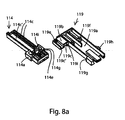
- Figures 8 to 13 show a system 110 designed in accordance with a second embodiment of the present invention.
- Said system 110 is substantially similar to the system 10 designed in accordance with the first embodiment of the present invention. Therefore, details and elements which are similar to - or which perform the same function as - those of the previously illustrated embodiment will be associated with the same alphanumerical references. For brevity, the description of such details and elements will not be repeated below, and reference will be made to the above description of the first embodiment.
- the second embodiment of the system 110 differs from the first embodiment of the system 10 for a few aspects relating to the structure, assembly and cooperation of the striker, designated herein as a whole by numeral 114, and of the thrust member, designated herein as a whole by numeral 119.
- the striker 114 can slide from the extracted position to the retracted position while being constrained - for a part of its travel - to the movement of the thrust member 119.
- the proximal slide 119a has a transversal extension 119b on which the proximal slide 114 is slideably mounted in the axial direction between the retracted position and the extracted position of the striker 114.
- the sliding between the transversal extension 119b and the proximal slide 114a is substantially of the "skid" type, i.e. the top of the proximal slide 114a has a first profile 114c, 114c' extending axially and coupled to a corresponding second profile 119c, 119c' also extending axially and carried under the transversal extension 119b.
- the first profile has a pair of ribs 114c coupled into a cavity 119c of the second profile, and a groove 114c' in turn coupled to a relief 119c' carried by the second profile.
- the optional return spring 15, which advantageously operates by traction, is mounted between a peg 114e carried by the striker 114, in particular by its proximal slide 114a, and a respective peg 119e carried by the thrust member 119, in particular by its transversal extension 119b.
- the peg 119e is carried in a receding channel (not numbered) extending axially on the top of the transversal extension 119b.
- the sensing means 23 are adapted to monitor the position of the thrust member 119, and are therefore adapted to provide an indication about the fact that the thrust member 119 is in the extracted position - and hence that the door D is in the pre-open condition.
- the mobile element 23a is associated with and pushed by the thrust member 119, e.g. by a transversal protrusion 119h thereof, which tends to push the mobile element 23a towards the normally idle condition.
- the transversal protrusion 119h while the thrust member 119h is moving towards the extracted position, goes past the mobile element 23a, the latter can move into the active condition.
- the locking mechanism 18 is adapted to act upon the thrust member 119, in particular releasing or holding the transversal protrusion 119h carried by the thrust member 119, e.g. by the proximal portion 119a.
- the slide 24 cooperates with the thrust member, e.g. with the transversal protrusion 119h.
- the slide 24 and the thrust member 119 preferably have respective complementary profiles 28 and 130 cooperating with each other.
- the profiles 28 and 130 are adapted to allow the thrust member 119 to be forcedly moved, by interference, from the extracted condition to the retracted condition through the action of a user pushing the swivelling door D towards the fully closed configuration.
- the profiles 28 and 130 are respective inclined sections of projecting noses (not numbered) carried by the slide 24 and, respectively, by the thrust member 119, in particular by the transversal protrusion 119h.
- the cooperation between the profiles 28 and 130 takes place in a manner similar to that described for the profiles 28 and 30 of the first embodiment of the system 10, with the difference that in this case such cooperation does not take place automatically through the return means 15, but through the action of a user pushing the swivelling door D into the fully closed configuration.
- the locking mechanism 18 therefore does not cooperate with or is constrained to the striker 114 directly, but via the thrust member 119.
- Such a configuration corresponds, in the system 110, to the one shown in Figure 9 , wherein the locking mechanism 18 is arranged in the locking condition, the thrust member 19 is held in the retracted condition by the locking mechanism 18 against the action of the stressing means 21, the striker 114 is in turn held in the retracted position by the return spring 15 and is also constrained to the thrust member 119 due to the abutment of the shoulder 114g against the shoulder 119g, the actuator member 20 is not electrically energized, and the sensing means 23 detect the retracted position of the thrust member 119. More in detail, the slide 24 is held in the locking position by the elastic member 26, while the cursor 36 is held in the idle position by the elastic element 38. Furthermore, the conductive wire 22 is in the extended condition and is held in traction. Also, the protrusion 119h abuts against the slide 24.
- the door D can be opened completely by a user, and crockery to be washed can thus be introduced into the wash chamber WT.
- the user can afterwards program the wash cycle of the dishwasher W by using suitable control interfaces typically provided on the door D.
- the door D of the dishwasher W will be fully closed and the engagement element 11 will be in the configuration shown in Figure 2 , coupled to the retaining element 16.
- the system 110 will always remain in the same configuration with a fully open door ( Figure 9 ), in that the thrust member 119 will be locked in the retracted condition, differently from the first embodiment illustrated herein (wherein it was brought into the retracted condition only as long as the door D remained in the closed position under the user's action).
- the striker 114 still behaves like a "dead bolt" holding the door D in the closed position.
- the striker 114 cannot translate from the retracted position to the extracted position because it abuts against the thrust member 119, which is locked by the locking mechanism 18, in particular through the effect of the abutment of the slide 24 against the transversal protrusion 119h.
- the engagement element 11 has the striker 114 in the retracted position
- the locking mechanism 18 is in the locking condition
- the thrust member 119 is locked in the retracted position
- the actuator means 20 are not electrically energized
- the sensing means 23 detect the retracted position of the thrust member 119.
- the slide 24 is held in the locking position by the elastic member 26, while the cursor 36 is held in the idle position by the elastic element 38.
- the conductive wire 22 is in the extended or elongated condition.
- the wash cycle programmed by the user can be automatically activated by the external control unit of the dishwasher W.
- the external control unit will send a current impulse to the actuator 20, so as to electrically energize it and bring the locking mechanism 18 into the unlocking condition.
- the flow of electric current causes the conductive wire 22 ( Figure 10 ) to heat up and behave in a manner similar to that already described for the first embodiment.
- the thrust member 119 is released from the locking mechanism 18 and the striker 114 is free to move into the extracted position ( Figure 11 ) through the effect of the connection with the retaining element 16, which is carried by the door D. Furthermore, the stressing means 21 can exert their thrust action, so as to assist the pre-opening of the door D. In fact, the thrust member 119 contributes to pushing the door D away from the cabinet C against the retaining action of the return means 15, which act upon the striker 114 and tend to hold it in the retracted position.
- the thrust member 119 is held slidable as a unit one together with the other, from the retracted condition to the extracted condition, with the striker 114, which moves from the retracted position to the extracted position, in particular thanks to abutment of the striker 114 against the thrust member 119 via the shoulders 114g and 119g. Furthermore, when the striker 114 and the thrust member 119 are in the extracted position or condition, the respective proximal slides 114a and 119a abut against the walls of the supporting body 12, e.g. against the perimeter of the lower half-shell 12a, so that any undesired excessive travel thereof is prevented.
- the striker 114 and the thrust member 119 are designed to, when they are in the extracted position, protrude further outwards from the supporting body 12 by an extension of a few centimetres (preferably 1 to 3 cm, but in certain conditions of use even more than 5 cm with respect to the normal projection of the striker 114 and of the thrust member 119 when they are in the retracted position or condition); in this way, the movement of the door D away from the access opening O, which is dependent on the above-mentioned extension, will be sufficient to allow the fluidic communication between the wash chamber WT and the environment outside the cabinet C.
- said extension is approx. 5.5 cm.
- the sensing means 23 detect the switching of the thrust member 119 into the extracted position, which in this case is indicative of the fact that the door D has reached the pre-open position.
- the actuator 20 When the electric current impulse supplied by the external control unit stops, the actuator 20 returns into the electrically de-energized condition and the locking mechanism 18 returns into the locking condition.
- the locking mechanism 18 when the locking mechanism 18 gets into the unlocking condition, it will stop the electric connection between the external control unit and the actuator 20. This occurs in a way similar to that already described for the first embodiment, but in this case the thrust member 119 performs the task of indicating the switching into the pre-open configuration
- the door D When the locking mechanism 18 returns into the locking condition and the striker 114 has moved into the extracted condition, the door D is in the pre-open condition, in which it is sufficiently spaced apart from the access opening O to allow the fluidic communication between the wash chamber WT and the outside environment.
- the distance between the door D and the access opening O allows the steam generated by the dishwasher W during a wash cycle to escape, thus allowing the crockery contained in the wash chamber WT to dry.
- the user can decouple the door D from the cabinet C by operating the mechanisms situated on the door D to bring the retaining element 16 into the idle position. In this way, the retaining element 16 and the striker 114 of the engagement element 11 will disengage from each other.
- the return means 15 will meet opposition from the thrust member 119 to returning the striker 114 into the fully retracted position.
- the return means 15 are constrained on one side to the thrust member 119, in particular to the proximal portion 119a thereof, which is held in its extracted condition by the stressing means 21.
- the thrust member 119 preferably carries an additional abutment 119i, e.g. carried by the transversal extension 119b, which is adapted to abut against a corresponding additional abutment 114i carried by the striker 114, e.g.
- the user can swivel the door D again towards the closed configuration, thereby pushing them further backwards.
- the thrust exerted by the door D will first cause an idle travel of the thrust member 119 until the shoulder 119g of the thrust member 119 abuts on the shoulder 114d of the striker, so as to make the striker 114 slidable as a unit with the thrust member 119 towards the retracted position and condition.
- the profile 130 carried by the thrust member 119 (in particular, by the transversal protrusion 119h) abuts against the profile 28, in turn carried by the slide 24, so as to generate thereon a thrust which is transversal to the thrust member 119.
- This action prevails over the countering force exerted by the elastic member 26.
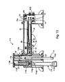
- the profile 30 of the thrust member 119 goes past the profile 28 of the slide 24, the thrust member 119 can no longer exert said transversal thrust, and therefore the elastic member 26 will return the slide 24 into the locking position, in particular under the thrust member 119 ( Figure 13 ).
- the backward movement of the slide 24 does not interfere with the position of the cursor 36 and therefore the elastic element 38 is not stressed, in particular thanks to the sliding coupling with some play between them.
- the system 110 will return into the configuration shown in Figure 9 ; the door D can then be opened again and brought past the pre-open configuration, and the washed - and at least partially dried - crockery can be picked up by the user; the process can then be restarted as previously described in order to carry out a new wash cycle.
- a locking mechanism only including the slide and the associated elastic member, omitting the cursor and the associated elastic element.
- the actuator is adapted to cooperate directly with the slide, e.g. by winding the conductive wire around the latter.
Description
- The present invention relates to a system for controlling the closing of a door of a household appliance, in particular for a washing machine, such as a dishwasher.
- In the field of household appliances, measures must be taken in order to allow closing an inner chamber obtained in a cabinet of such appliances, which typically consists of a wash chamber of a washing machine, such as a dishwasher. In this regard, a door is employed which is movable relative to the cabinet in a manner such as to open or close an access opening, through which the inner chamber can communicate with the environment outside the household appliance.
- Generally, such systems comprise an engagement element mounted on either one of said cabinet or said door, and a retaining element mounted on the other one of the door and the cabinet. The retaining element is adapted to releasably retain the engagement element, so as to constrain the door to the cabinet when the household appliance is in use.
- The coupling between the engagement element and the retaining element is typically accomplished by a user, who causes them to abut against each other by manually pushing the door against the cabinet until it fully closes. The decoupling between the engagement element and the retaining element is also accomplished by the user, who operates suitable control interfaces (e.g. provided on the front wall of the door or on the front or top face of the cabinet) to activate internal mechanisms of the retaining element in order to disengage the engagement element from the retaining element.
-
WO 2009/146874 A1 discloses a dishwasher having a rinsing container that can be closed by a pivoting door, wherein to provide locking a locking device disposed on the door engages into a clamp disposed on the rinsing container, and wherein to open the door in gaps the clamp is disposed on an adjustable connecting rod that is adjustable in the opening direction by means of a drive. In order to also ensure the automatic retracting of the clamp when the electric gear motor is replaced with a more cost-effective drive, the invention provides means for returning the clamp at least approximately to the initial position thereof opposite to the opening direction as a result of the further opening movement of the door. -
WO 2011/141542 A1 discloses a dishwasher comprising a body, a door which provides access into the body and opens from the top downwards by rotating around the horizontal axis, a door latch which provides the door to be locked, and a door opening mechanism having a linear actuator that provides the door to be opened automatically at the end of the washing and drying processes such that some gap remains between the door and the body. - It is one object of the present invention to provide a system for closing a door of a household appliance which offers improved performance while at the same time being manufactured in a simple and economical manner.
- It is another object of the present invention to provide a system for closing a door of a household appliance which allows to pre-open the door in an automatic and safe manner, so as to put the wash chamber in fluidic communication with the outside environment through the access opening. This device proves to be particularly advantageous in washing machines, e.g. dishwashers, because it allows the steam generated during the wash cycle to escape into the outside environment, thereby contributing to at least partially drying the items contained in the wash chamber.
- According to the present invention, these and other objects are achieved through a system designed as set out in the appended claim 1.
- It is understood that the appended claims are an integral part of the technical teachings provided in the description of the present invention.
- Further features and advantages of the present invention will become apparent from the following detailed description, which is supplied by way of non-limiting example with reference to the annexed drawings, wherein:
-
Figure 1 is a perspective view of a dishwasher incorporating a system for controlling the closing of a door of a household appliance in accordance with a first exemplary embodiment of the present invention. -
Figure 2 is a partial schematic top view of the dishwasher ofFigure 1 , which is shown without the lid and with the door in the fully closed position; -
Figure 3 is a partial perspective view of the system of the preceding figures, which shows some internal components thereof; -
Figure 4 is an exploded perspective view of the system shown in the preceding figures; -
Figure 4a is a perspective view of a set of components of the system shown inFigure 4 ; -
Figures 5 to 7 are top views of the system of the preceding figures, shown in a sequence of operating conditions; -
Figure 8 is an exploded perspective view of a second exemplary embodiment of the system according to the present invention; -
Figure 8a is a perspective view of a set of components of the system shown inFigure 8 ; and -
Figures 9 to 13 are top views of the system ofFigure 8 , shown in a sequence of operating conditions. - With particular reference to
Figure 1 , W designates as a whole one example of a washing machine subject to installation of a first and, respectively, a second exemplary embodiments of asystem system - With particular reference to
Figure 1 , dishwasher W has a cabinet C in which a wash tub or chamber WT is defined, which is adapted to receive the crockery to be washed. Wash tub WT has an access opening O, through which it communicates with the outside environment and can therefore receive the crockery. In addition, dishwasher W has a door D adapted to open (Figure 1 ) and close (Figure 2 ) access opening O. - Access opening O is provided on a front face of cabinet C and, preferably, door D is tiltably mounted relative to cabinet C, e.g. being hinged under the latter to a horizontal axis. In the embodiments shown, access opening O has a peripheral sealing gasket SG that allows wash tub WT to be closed fluid-tight when door D is in a fully closed condition.
- In the illustrated embodiments, cabinet C has a lid L, which is advantageously situated on the top of said cabinet C.
- In
Figure 2 , washing machine W is shown only partially without lid L which is typically present on the top of cabinet C. Machine W preferably has a crossbar CB situated on a wall of wash tub WT. - With particular reference to
Figures 3 to 7 , there is shown a first embodiment ofsystem 10 according to the present invention. - The system is adapted to allow closing door D of dishwasher W, and comprises an
engagement element 11 to be mounted on cabinet C, e.g. to crossbar CB positioned between cabinet C and lidL. Engagement element 11 is adapted to be releasably held by aretaining element 16 to be mounted on door D, e.g. on the rear face thereof facing towards access opening O. - Retaining
element 16 is adapted to releasably retainengagement element 11, so as to constrain door D to cabinet C when dishwasher W is in use. In the illustrated embodiments,engagement element 11 is mounted on cabinet C and retainingelement 16 is mounded on door D. -
Engagement element 11 comprises a supportingbody 12 which, in the illustrated embodiments, is secured to cabinet C, and astriker 14 associated with supportingbody 12 and adapted to be releasably coupled to retainingelement 16 mounted on door D, so as to constrain door D to cabinet C when dishwasher W is in use. In both of the illustrated embodiments, supportingbody 12 is designed as an internally hollow casing, e.g. including a pair of half-shells ortrays - In both illustrated embodiments, half-
shells body 12 are made of plastic material, e.g. by injection moulding. Preferably, supportingbody 12 is screwed to cabinet C of household appliance W, e.g. at crossbar CB. - As will become apparent from the following description,
striker 14 is movably mounted relative to supportingbody 12 between a retracted position (Figures 2 ,3 ,5 and7 ) and an extracted position (Figure 6 ). Advantageously, the movement ofstriker 14 is guided by supportingbody 12, particularly by inner walls of the latter. Preferably,striker 14 is slideable relative to supportingbody 12. In particular,striker 14 is made of plastic material, e.g. by injection moulding. - In both illustrated embodiments, in the retracted
position striker 14 partially protrudes from supportingbody 12, whereas in the extractedposition striker 14 protrudes further out by an additional section. Preferably,striker 14 protrudes through a slot (not numbered) provided on the front face of cabinet C of dishwasher W whereto thewhole engagement element 11 has been mounted. - In particular, when
striker 14 is coupled to retainingelement 16 and moves to the extracted position, retainingelement 16 moves away from supportingbody 12, which leads to an outward movement of door D, still constrained to cabinet C, which however will no longer be closed fluid-tight at access opening O. - Retaining
element 16 is substantially of a per se known type, e.g. with a slotted container body housing an engagement mechanism to whichstriker 14 can gain access through the slot in order to be releasably coupled to said engagement mechanism. Generally, said engagement mechanism can oscillate between a working position and an idle position, and comprises a swivelling member, the movement of which is countered by an elastic member, and with which thestriker 14 is adapted to releasably engage. In the working position, the revolving member of the engagement mechanism holdsstriker 14 when door D is closed. In the idle position, instead, the revolving member of the engagement mechanism releasesstriker 14 when the user operates a suitable release mechanism (not shown), e.g. including a push-button, a lever or a knob, located on door D. - Some examples of such a
retaining element 16 are widely known in the industry and have been described in detail in many prior-art documents. For completeness' sake, Italian patent applications no.T097A1120 T02000A000383 T02001A01003 element 16 will not be described any further herein. - When
striker 14 is coupled to retainingelement 16 and is in the retracted position,engagement element 11 is arranged as shown inFigure 2 , wherein door D is in a fully closed condition, thereby closing fluid-tight access opening O of wash chamber WT. Instead, whenstriker 14 is coupled to retainingelement 16, but is in the extracted position, door D gets into a pre-open condition, since there is a small gap between it and access opening O, which puts wash chamber WT in fluidic communication with the environment outside cabinet C. In particular, in the pre-open condition the steam contained in wash chamber WT (generated, for example, during a wash cycle) can escape from dishwasher W, so that the crockery contained therein will be at least partially dried. - In other words, when
striker 14 is coupled to retainingelement 16 and moves into the extracted position, it allows retainingelement 16 to be moved away from supportingbody 12, resulting in door D moving away from cabinet C. Due to the coupling betweenstriker 14 and retainingelement 16, door D will remain constrained to cabinet C without however closing access opening O fluid-tight. - With particular reference to
Figures 4 and5 ,engagement element 11 further comprises a locking mechanism, designated as a whole 18. In both of the illustrated embodiments, lockingmechanism 18 is mounted on supportingbody 12; in particular, it is contained in the cavity defined by supportingbody 12 itself.
locking mechanism 18 tends to switch
from an unlocking condition (Figure 6 ), in which it is adapted to allow releasingstriker 14, allowing the latter to move from the retracted position to the extracted position whenstriker 14 is coupled to retainingelement 16,
to a locking condition (Figures 3 ,5 ,7 ), in which it is adapted to allow holdingstriker 14 whenstriker 14 is in the retracted position. - Furthermore,
engagement element 11 comprises electrically controlled actuator means 20 adapted to control the switching of lockingmechanism 18 from the locking condition to the unlocking condition. For example, said switching occurs whenactuator 20 is energized by an electric current flowing therethrough. - In the illustrated embodiments,
actuator 20 is connected to an external control unit associated with the household appliance W and capable of supplying electric current toactuator 20 in predetermined conditions of use. In both of the illustrated embodiments, actuator means 20 are mounted on supportingbody 12, e.g. housed in the cavity defined within the latter. - Preferably,
engagement element 11 further comprises return means 15 adapted to optionally returnstriker 14 into the retracted position when saidstriker 14 is decoupled from retainingelement 16. In particular, return means 15 are mounted on supportingbody 12. This preventsstriker 14 from protruding excessively - possibly jeopardizing the users' safety - from cabinet C of dishwasher W when a user decouplesstriker 14 from retainingelement 16 by operating suitable release mechanisms provided on dishwasher W to move door D from the pre-open condition to the fully open condition. - More preferably, the return means comprise elastic return means, e.g. comprising a
return spring 15. In particular, elastic return means 15 are adapted to operate by traction. -
System 10 further comprises athrust member 19 capable of exerting a thrust on door D in the direction of movement ofstriker 14 from the retracted position to the extracted position, thus facilitating the switching of door D into the pre-open condition whenstriker 14 is coupled to retainingelement 16 andlocking mechanism 18 is in the unlocking condition. In this manner, the switching of door D from the fully closed condition to the pre-open condition is made easier and more reliable. - In the illustrated embodiment, the use of
thrust member 19 makes it possible to optionally adopt return means 15 associated withstriker 14. In fact, when door D is in the fully closed condition, the movement ofstriker 14 from the retracted position to the extracted position takes place against the action of return means 15. Although such movement may tendentially be promoted by the weight of door D (which is connected tostriker 14 via the coupling with retaining element 16) and, possibly, by the elastic compression load exerted by gasket SG compressed between door D and cabinet C, it may however risk to be significantly hindered or even prevented by return means 15. Thanks to the presence of the thrust member, instead, the action of return means 15 can be effectively countered becausethrust member 19 prevents return means 15 from keeping door D from oscillating when lockingmechanism 18 switches to the unlocking condition. - In particular, if return means 15 are present, the return force exerted by them is advantageously smaller than the thrust force exerted by
thrust member 19. -
Engagement element 11 preferably includes said thrustmember 19, e.g. substantially elongated in shape, which is movably mounted relative to supportingbody 12 so as to exert said thrust, thus switching from a retracted condition to an extracted condition. This allows to obtain a compact configuration ofsystem 10 by integratingthrust member 19 into the structure ofengagement element 11. - In particular, in the retracted condition only a small section (or none at all) of
thrust member 19 protrudes from supportingbody 12, whereas in the extracted condition thrustmember 19 protrudes further out by an additional length. - Advantageously,
thrust member 19 is housed within the supportingbody 12 and slides relative to the latter, e.g. being guided by inner walls of said supportingbody 12. - In both of the illustrated embodiments,
engagement element 11 further comprises elastic stressing means 21 acting uponthrust member 19 and tending to bring it into the extracted condition. - Preferably,
system 10 further comprises elastic stressing means 21 acting upon saidthrust member 19 and tending to bring it into the extracted condition. In both of the illustrated embodiments, elastic stressing means 21 are mounted between supportingbody 12 and thrustmember 19, and are adapted, for example, to operate by traction, pullingthrust member 19 outwards from the supporting body. Advantageously, the elastic stressing means comprise at least onetraction spring 21; in the illustrated embodiments a pair of traction springs 21 are employed. - In both of the illustrated embodiments,
striker 14 and thrustmember 19 are movable in parallel directions. - Preferably,
striker 14 and thrustmember 19 are mounted to each other in a mutually guided manner, particularly in a slideable fashion. - More preferably,
striker 14 and thrustmember 19 are mutually integral with each other while sliding from the respective retracted position or condition to the respective extracted position or condition, whenstriker 14 is coupled to said retainingelement 16 andlocking mechanism 18 releases at least one ofstriker 14 and thrustmember 19, thereby switching from the locking condition to the unlocking condition. This is particularly useful to avoid that, whilestriker 14 is moving from the retracted position to the extracted position,thrust member 19 and door D (the position of which depends on the position ofstriker 14 because of the connection still existing betweenengagement element 11 and retaining element 16) might get into mutual positions not allowing a correct thrust action towards the pre-open position. In the illustrated embodiments,thrust member 14 is made slidable as a unit withstriker 19 bystriker 14 resting onthrust member 19. - Advantageously,
striker 14 can slide relative to thrustmember 19 along at least a part of the travel from the extracted position to the retracted position, under the control of said return means 15, whenstriker 14 and the retaining element are decoupled. In the first embodiment shown herein,striker 14 is slideable from the extracted position to the retracted position independently of the movement ofthrust member 19. - In both embodiments,
striker 14 and thrustmember 19 have reciprocalproximal slides proximal slide 14a has atransversal extension 14a in whichproximal slide 19a is slideably mounted, advantageously in a "drawer-like" fashion, in the axial direction between the retracted condition and the extracted condition ofthrust member 19. With particular reference toFigure 4a ,transversal extension 14b hassuitable slots 14c extending in the axial direction, within which complementary protrusions can slide, e.g. pegs 19c, carried byproximal slide 19a. - In both embodiments,
striker 14 and thrustmember 19 have reciprocaldistal appendices proximal slides element 16 and said door D. Particularly, eachdistal appendix Figure 4a ) formed at the front inproximal slides - In the illustrated embodiments, unlike
distal appendices proximal portions body 12, without protruding externally thereto during the movement ofstriker 14 and ofthrust member 19. - In this first embodiment illustrated herein, return
spring 15, which advantageously operates by traction, is mounted between apeg 14e carried bystriker 14, in particular byproximal slide 14a, and arespective peg 12e carried by supportingbody 12. - In both of the illustrated embodiments, each stressing
spring 21, which advantageously operates by traction, is mounted between arespective peg 19f carried byproximal slide 19a and arespective peg 12f carried by supportingbody 12. - Particularly, if
return spring 15 is present, the force exerted by it onstriker 14 is advantageously smaller than the force exerted by stressingsprings 21 onthrust member 19. - In the illustrated embodiments, the respective
proximal portions respective shoulders shoulder 14g is adapted to abut againstshoulder 19g in order to keep, when in use,thrust member 19 in abutment with door D, so as to exert an optimal thrust towards the pre-open position. - By way of example, the shoulder of
striker 14 is defined by anupper corner 14g brought into an axially forward position bytransversal extension 14b, whereas the shoulder ofthrust member 19 is defined by atooth 19g protruding upwards fromproximal portion 19a in an axially forward position of the latter. - Of course, as
striker 14 returns into the retracted position, the abutment betweenshoulders striker 14 alongthrust member 19. - Preferably, locking
mechanism 18 is adapted to constrain at least one ofstriker 14 and thrustmember 19, thus preventing it from moving to the extracted position and, respectively, to the extracted condition when
striker 14 and/or thrustmember 19 is in the respective retracted position or condition, and
locking mechanism 18 is in the locking condition. - In this manner, locking
mechanism 18 can be designed with different possible configurations, since it can be structured for: - acting directly upon
striker 14, thus preventing door D from moving away from cabinet C against the action ofthrust member 19, and/or - acting directly upon
thrust member 19, thus inhibiting the thrust against door D required forstriker 14 to move, allowing oscillation in the pre-open position; in this case, however, it is preferable thatthrust member 19 cooperates withstriker 14 to prevent the latter from moving untilthrust member 19 is in the retracted condition, locked by locking mechanism 18 (e.g. as it happens in the second embodiment of the present invention). - Preferably, locking
mechanism 18 is adapted to operate in a transversal direction relative to the direction of movement ofstriker 14 and/or ofthrust member 19. - In this first embodiment, locking
mechanism 18 is adapted to act uponstriker 14, in particular by releasing or holding atransversal protrusion 14h carried bystriker 14, e.g. bytransversal extension 14b. - Preferably,
system 10 comprises sensing means 23 adapted to detect the extracted position or condition of at least one ofstriker 14 and thrustmember 19. This allows to obtain an indirect indication about the state of door D in operation. In this first embodiment, the sensing means are adapted to monitor the position ofstriker 14, and are therefore adapted to provide an indication about the fact thatstriker 14 is in the extracted position - and hence door D is in the pre-open condition. - Advantageously, sensing means 23 comprise a
mobile element 23a, movable relative to said supportingbody 12 in a manner controlled by at least one ofstriker 14 and thrustmember 19, and asensitive member 23b, which is adapted to provide an indication about the position taken bymobile element 23a. - For example,
mobile element 23a can be moved in a guided manner from supportingbody 12, in particular in a transversal direction relative to the direction in whichstriker 14 or thrustmember 19 is adapted to move. Advantageously,mobile element 23a is housed within the casing formed by supportingbody 12. Preferably, the mobile element is acursor 23a, which on one side cooperates withstriker 14 or withthrust member 19, and on the other side cooperates withsensitive member 23b. - For example, the sensitive member is a
switch 23b, particularly a microswitch, adapted to be operated bymobile element 23a, e.g. by an appendix (not numbered) carried bymobile element 23a and capable of activatingswitch 23b according to predetermined criteria. - Preferably,
mobile element 23a is adapted to be pushed in abutment with at least one ofstriker 14 and thrustmember 19 through the effect of elastic counteringmeans 25. More in detail, the action of elastic counteringmeans 25 takes place in a manner such thatmobile element 23a is brought from a normally idle condition (Figures 3 ,5 and7 ), in which it does not actuatesensitive member 23b whenstriker 14 and/or the thrust member are in the retracted position or condition, to an active condition (Figure 6 ), in which it actuatessensitive member 23b whenstriker 14 and/or thrustmember 21 are in the extracted position or condition. In this first embodiment illustrated herein,mobile element 23a is associated and pushed bystriker 14, e.g. bytransversal protrusion 14h, which tends to push it towards the normally idle condition. Whentransversal protrusion 14h, while the striker is moving towards the extracted position, goes pastmobile element 23a, the latter can move into the active condition. - For example,
mobile element 23a may include alug 23c, and the supporting body may have acorresponding lug 12c, in turn extending through aslot 23d onmobile element 23a. Moreover, betweenlugs means 25 may be mounted, particularly tending to move saidlugs mobile element 23a to push againststriker 14 and/or thrustmember 19. - Preferably,
actuator 20 is adapted to switch from a normally extended condition (Figures 3 ,5 and7 ) to a contracted condition (Figure 6 ). In the extended condition,actuator 20 allows lockingmechanism 18 to get into the locking condition; in the contracted condition, instead, actuator 20 brings lockingmechanism 18 into the unlocking condition. - More preferably,
actuator 20 comprises a shape-memoryconductive element 22 mechanically connected to and cooperating with the locking mechanism. In particular,conductive element 22 is made of a shape memory alloy (SMA) capable of taking a preset shape (in this case corresponding to the shape taken in the contracted condition) following a variation in its temperature which is due, in the illustrated embodiments, to heating through the Joule effect caused by current flowing through it. - In alternative variant embodiments not shown,
conductive element 22 may be replaced with different types of electric actuators; in such variants, the actuator may include an electromagnetic actuator (e.g. of the solenoid type) or an electrothermal actuator (e.g. of the wax type). Said types of actuators are per se known in the art and will not therefore be described for the sake of brevity. - As will be described in detail below, in the illustrated embodiments
conductive element 22 is provided in the form of a wire mechanically connected to - and acting upon - lockingmechanism 18 in order to bring the latter from the normal locking condition to the unlocking condition. - In both of the illustrated embodiments,
conductive element 22 is advantageously connected in series to a positive temperature coefficient (PTC) resistor. - Preferably, locking
mechanism 18 comprises aslide 24 which can move, in particular slide, relative to supportingbody 12 from a locking position (Figures 3 ,5 and7 ) to an unlocking position (Figure 6 ). In the locking position, slide 24 is adapted to hold at least one ofstriker 14 and thrustmember 19 when it is in the retracted position and, respectively, in the retracted condition, thereby preventing it from moving to the extracted position and, respectively, into the extracted condition. In the unlocking position, instead, slide 24 allows the movement of at least one of striker 14 (from the retracted position to the extracted position) and thrust member 19 (from the retracted condition to the extracted condition) through the effect of an electric energization ofactuator 20. In addition, lockingmechanism 18 comprises anelastic member 26 tending to holdslide 24 in the locking position. In the illustrated embodiments,elastic member 26 is interposed between supportingbody 12 andslide 24. Preferably,elastic member 26 is a spring, e.g. a compression-preloaded spring, advantageously of the coil type. - In the first embodiment illustrated herein, slide 24 cooperates with
striker 14. -
Slide 24 is preferably positioned against a protrusion formed transversally in at least one ofstriker 14 and thrustmember 19, whenslide 24 is in the locking position andstriker 14 or the thrust member is in the retracted position or, respectively, in the retracted condition. In the first embodiment shown herein, said protrusion advantageously coincides withtransversal protrusion 14h ofstriker 14. - Therefore, in both of the illustrated
embodiments locking mechanism 18 has a substantially ratchet-like property, whereinslide 24 behaves like a ratchet adapted to prevent the movement of at least one ofstriker 14 and thrustmember 19. In particular, whenengagement element 11 and retainingelement 16 are coupled to each other,striker 14 is subject, on one side, to "extraction" forces due to the thrust force exerted bythrust member 19 and to the weight of door D, possibly assisted by the elastic compression of sealing gasket SG. On the other side, still whenengagement element 11 and retainingelement 16 are coupled to each other,striker 14 is subject to "retraction" forces due to the action of return means 15 (if present), which forces are generally smaller than the opening forces. Therefore, when lockingmechanism 18 is in the locking condition, slide 24 that constrainsstriker 14 prevents the "extraction" forces from actuating the system to bring door D into the pre-open condition. - With particular reference to
Figure 5 , in thefirst embodiment slide 24 andstriker 14 preferably have respectivecomplementary profiles Profiles striker 14 from the extracted position to the retracted position, possibly with the contribution of return means 15, thus countering the action ofelastic member 26. In this regard, if return means 15 are present, they are so sized as to exert a return force, e.g. an elastic pulling force, having such intensity as to overcome the elastic countering force exerted byelastic member 26. - In the first embodiment shown herein, profiles 28 and 30 are respective inclined sections of projecting noses (not numbered) carried by
slide 24 and, respectively, bystriker 14, in particular bytransversal protrusion 14h. The cooperation betweenprofiles system 10. - In the illustrated embodiments, locking
mechanism 18 further comprises acursor 36 movable by means ofactuator 20 and movably, in particularly slideably, mounted relative to supportingbody 12 from an idle position (Figure 3 ,5 and7 ) to an active position (Figure 6 ). In the idle position,cursor 36 allowsslide 24 to move from the unlocking position to the locking position under the action ofelastic member 26. In the active position, instead, cursor 36 drags slide 24 from the locking position to the unlocking position against the action ofelastic member 26 whenactuator 20 is electrically energized. Furthermore, lockingmechanism 18 comprises anelastic element 38 tending to holdcursor 36 in the idle position. In the illustrated embodiments,elastic element 38 is mounted between supportingbody 12 andcursor 36. Preferably,elastic element 38 is a spring, e.g. a compression-preloaded spring, advantageously of the coil type. - Preferably,
cursor 36 is mechanically connected to shape-memory element 22, and is therefore adapted to be dragged by the latter between the idle position and the active position. In the illustrated embodiments, the shape-memory element is provided in the form of aconductive wire 22 connected tocursor 36, e.g. arranged in a U fashion to embrace with its bend a part ofcursor 36. Preferably, saidconductive wire 22 is wound with its bend along a peripheral section of a prominent portion 39 (which in the illustrated embodiment is a substantially annular portion surrounding an inner cavity into which the elastic element is placed during assembly) ofcursor 36, e.g. it is inserted into a perimetric groove (not numbered) formed in said peripheral section. - In the illustrated embodiments, slide 24 and
cursor 36 are coupled together with some sliding play. Preferably, the coupling betweenslide 24 and the cursor is substantially of the so-called "coulisse" type. More preferably,cursor 36 has a mushroom-shapedend 40 andslide 24 has a profiledcavity 42 that houses mushroom-shapedend 40 with some axial play. Even more preferably, mushroom-shapedend 40 has a transversally wider head and a narrower neck which tapers away from the head; in its turn,cavity 42 has a transversally wider proximal portion that houses the head with some axial play, and a transversally narrower distal portion that extends from the proximal portion and allows, through it, the axial sliding of the neck (details not numbered). Advantageously, profiledcavity 42 is defined by a pair ofside arms 44 situated at the end ofslide 24, which converge transversally inwards at their free ends. For example, each one ofside arms 44 defines a substantially hook-like shape. Advantageously, on top ofside arms 44, after they have been coupled tohead 42, a closing crosspiece (not numbered) is mounted, e.g. by interference fit; this reduces the risk ofhead 42 undesirably coming out by climbing overside arms 44. - In the illustrated embodiments,
elastic element 38 exerts an elastic return force oncursor 36 which is greater than the elastic return force exerted byelastic member 26 onslide 24. In this way,elastic element 38 can effectively returncursor 36 into the active position, in particular by reliably pulling backconductive wire 22 with a high-intensity force. Also,elastic member 26 can thus returnslide 24 into the locking position, without however hindering - by exerting excessive resistance - the action of return means 15 (if present), which forcedly return theslide 24 into the retracted position when the user causes the decoupling ofstriker 14 ofengagement element 11 from retainingelement 16 by operating a suitable release mechanism provided on door D or on cabinet C. - In the illustrated embodiments, slide 24 and/or
cursor 36 are movable in a direction which is substantially transversal, preferably orthogonal, to the direction of movement ofstriker 14 and/or of thrust member 19 (if present). For example, slide 24 andcursor 36 are movable in the same direction. - Preferably, locking
mechanism 18 is adapted to stop the electric energization ofactuator 20 after lockingmechanism 18 has gone into the unlocking condition. More preferably, theactuator 20 comprises asafety switch 45, e.g. a microswitch, controlled by lockingmechanism 18 and adapted to electrically disconnectactuator 20 from the external control unit when lockingmechanism 18 gets into the unlocking condition. In the illustrated embodiments, switch 45 is electrically connected downstream of one of the power contacts (not numbered) that allow connectingactuator 20 to the external control unit. For example, power contacts 46 are electrically connected to the ends ofconductive wire 22. - Preferably, switch 45 comprises a fixed contact (not numbered) and a mobile contact (not numbered) cooperating with locking
mechanism 18 in a manner such that it is moved away from the fixed contact as lockingmechanism 18 reaches the unlocking condition. In the illustrated embodiments, the mobile contact has a profiled protrusion adapted to abut against a correspondingprotrusion 52 carried by lockingmechanism 18, e.g. bycursor 36, so that the mobile contact will detach itself, e.g. by bending, from the fixed contact when lockingmechanism 18 reaches the unlocking condition, e.g. whencursor 36 reaches the active position. Preferably, the profiled protrusion of the mobile contact has a cusp-like profile. Also preferably,protrusion 52 has an inclined section substantially conjugated to the cusp-profiled section of the mobile contact. - With particular reference to
Figure 5 ,elastic member 26 is preferably axially interposed between alug 58 protruding fromslide 24 and a fixedshelf 60 protruding from supportingbody 12, e.g. from lower half-shell 12b. Preferably,shelf 60 is housed in a guide aperture (not numbered) formed throughslide 24. In this manner,elastic member 26 can pushlug 58 as a unit withslide 24 until a terminal edge of said guide aperture abuts against fixedshelf 60, which corresponds to the locking position ofslide 24. Therefore, fixedshelf 60 also acts as an end-of-travel element forslide 24. - Preferably,
cursor 36 is slideable in supportingbody 12, being preferably guided by inner walls of supportingbody 12, e.g. by walls of lower half-shell 12b and by the back walls of both half-shells - Preferably,
elastic element 38 is axially interposed between an additional lug (e.g. prominent portion 39), protruding fromcursor 36, and an additional fixedshelf 66, protruding from supportingbody 12, e.g. from lower half-shell 12b. Preferably,additional shelf 66 is housed in an additional guide aperture (not numbered) formed throughcursor 36, e.g. in the vicinity of the additional lug (throughprominent portion 39 in the illustrated embodiments). In this manner,elastic element 38 can pushadditional lug 39 as a unit withcursor 36 until a terminal edge of theadditional guide aperture 68 abuts against additional fixedshelf 66, which corresponds to the idle position ofcursor 36. Therefore, additional fixedshelf 66 also acts as an end-of-travel element for the cursor. - In the illustrated embodiments, switches 23b and 45, along with resistor PTC, are carried by a support or board PCB on which a printed circuit is formed which connects said switches and resistor. Advantageously, support PCB has two pairs of
connection terminals switch 23b, respectively. - The following will describe the operation of the first embodiment illustrated herein of
system 10 according to the present invention. - Reference will initially be made to the configuration of dishwasher W with door D partially open (
Figure 1 ). - Such a configuration corresponds, in
system 10, to the one shown inFigure 7 , whereinengagement element 11 hasstriker 14 held in the retracted position by return means 15,locking mechanism 18 is arranged in the locking condition,thrust member 19 is held in the extracted condition by stressingmeans 21,actuator 20 is not electrically energized, and sensing means 23 detect the retracted position ofstriker 14. More in detail, slide 24 is held in the locking position byelastic member 26, whilecursor 36 is held in the idle position byelastic element 38. Furthermore,conductive wire 22 is in the extended condition and is held in traction. Also,protrusion 14h abuts againstslide 24. - In this situation, with
engagement element 11 decoupled from retainingelement 16, door D can be opened completely by a user, and crockery to be washed can thus be introduced into wash chamber WT. The user can afterwards program the wash cycle of dishwasher W by using suitable control interfaces typically provided on door D. - Let us now consider the action carried out by the user while closing door D against cabinet C. During this operation, retaining
element 16 andstriker 14 ofengagement element 11 are brought close to each other and coupled together, while at the same time door D pushes thrustmember 19 from the extracted condition to the retracted condition, guided bystriker 14, in particular byside extension 14b (in this first embodiment illustrated herein, throughslots 14c). - After said closing action carried out by the user, door D of dishwasher W will be fully closed and
engagement element 11 will be in the configuration shown inFigures 2 and3 , coupled to retainingelement 16. Note that thrust member 19 - in abutment with door D - exerts its action against door D, but cannot cause it to open becausestriker 14 behaves like a "dead bolt" holding door D in the closed position. In fact, althoughstriker 14 can translate from the retracted position to the extracted position, it is stopped and firmly held in the retracted position by lockingmechanism 18, in particular through the effect of the abutment ofslide 24 against striker 14 (e.g. againsttransversal protrusion 14h). - In such a fully closed configuration of the door,
engagement element 11 hasstriker 14 in the retracted position, lockingmechanism 18 is in the locking condition,thrust member 19 is in the retracted position, actuator means 20 are not electrically energized, and sensing means 23 detect the retracted position ofstriker 14. More in detail, slide 24 is held in the locking position byelastic member 26, whilecursor 36 is held in the idle position byelastic element 38. Furthermore,conductive wire 22 is in the extended or elongated condition. - Therefore, the wash cycle programmed by the user can be automatically activated by the external control unit of dishwasher W.
- It should now be considered that, at the end of said wash cycle carried out by washing machine W, the external control unit will send a current impulse to actuator 20, so as to electrically energize it and bring
locking mechanism 18 into the unlocking condition. - The flow of electric current causes
conductive wire 22 to heat up and rapidly switch from the extended condition to the contracted condition, thus getting shorter and draggingcursor 36 backwards from the idle position to the active position, against the action of elastic element 38 (Figure 6 ). Therefore, after a short idle travel (e.g. approx. half millimetre),cursor 36 will drag alongslide 24 from the locking position to the unlocking position. More in detail, mushroom-shapedend 40 will abut against the converging ends ofside arms 44, thereby causingslide 24 to be dragged backwards. - In the illustrated embodiments,
conductive wire 22 is designed to reduce its length by approx. 3,5% while switching from the longer extended condition to the shorter contracted condition. - In this way,
striker 14 is free to move into the extracted position (Figure 6 ) through the effect of the connection with retainingelement 16, which is carried by door D, with the assistance of thethrust member 19. In fact, thethrust member 19 contributes to pushing the door D away from the cabinet C against the retaining action of the return means 15, which act upon thestriker 14 and tend to hold it in the retracted position. When thestriker 14 and thethrust member 19 are in the extracted position or condition, the respectiveproximal slides body 12, e.g. against the perimeter of the lower half-shell 12a, so that any undesired excessive travel thereof is prevented. - At this stage, the
shoulder 14g of thestriker 14 advantageously abuts against theshoulder 19g of thethrust member 19, so that thestriker 14 and thethrust member 19 are made as a unit with each other while moving towards the respective extracted position or condition. - Preferably, the
striker 14 and thethrust member 19 are designed to, when they are in the extracted position, protrude further outwards from the supportingbody 12 by an extension of a few centimetres (preferably 1 to 3 cm, but in certain conditions of use even more than 5 cm with respect to the normal projection of thestriker 14 and of thethrust member 19 when they are in the retracted position or condition); in this way, the movement of the door D away from the access opening O, which is dependent on the above-mentioned extension, will be sufficient to allow the fluidic communication between the wash chamber WT and the environment outside the cabinet C. In the illustrated embodiments, said extension is approx. 5.5 cm. - Furthermore, when the
striker 14 goes past themobile element 23a, the sensing means 23 detect the switching of thestriker 14 into the extracted position, which in this case is indicative of the fact that the door D has reached the pre-open position. - When the electric current impulse supplied by the external control unit stops, the
actuator 20 returns into the electrically de-energized condition and thelocking mechanism 18 returns into the locking condition. - At this stage, when the electric current impulse has stopped the
conductive wire 22 starts cooling down and gradually returns into the extended condition, thus becoming longer, and, correspondingly, theelastic element 38 progressively pushes thecursor 36 forwards towards the idle position by following the bend of theconductive wire 22, which is extending; in particular, the mushroom-shapedend 40 of theelastic element 38 moves gradually forwards towards the idle position by following the elongation of theconductive wire 22. As a consequence, also theside arms 44 of theslide 24, which had previously been dragged backwards by thecursor 36, will tend to follow the forward movement of the mushroom-shapedhead 40 through the action of theelastic member 26, and will gradually return theslide 24 into the locking position. - In the illustrated embodiments, the elastic element 37 has an elastic compression preload of approx. 0.5 kg, and the
conductive wire 22 has a diameter of approx. 0.38 mm. The preload of theelastic element 38 is adapted to the diameter of theconductive wire 22, in order that thecursor 36 can be effectively returned into the idle position. - In the illustrated embodiments, the
elastic member 26 has an elastic compression preload of approx. 200 g, which is smaller than that of the elastic element. In fact, the main function of theelastic member 26 is to prevent theslide 24 from correctly rearranging itself into the locking position, in particular should the return action exerted on theconductive wire 22 by theelastic element 38 cause any accidental jamming or seizure. - In the illustrated embodiments, the
conductive wire 22 is designed to cool down and go back from the shorter contracted condition to the longer extended condition within approx. 13 sec. - Optionally, when the
locking mechanism 18 gets into the unlocking condition, it will stop the electric connection between the external control unit and theactuator 20. This measure has been conceived in order to avoid any damage to theconductive wire 22 which might be caused by overheating due to an accidentally excessive duration of the energization current impulse supplied by the external control unit (e.g. caused by said impulse not being interrupted within nominal times). This can be accomplished in different ways. - A first possible way is to use the
safety switch 45. More in detail, when thecursor 36 reaches the active position, it interferes with the safety switch, thus opening it and breaking the current flow through theconductive wire 22. In particular, theprotrusion 52 of thecursor 36 rests against the profiled protrusion of the mobile contact of thesafety switch 45, thereby moving it away from the associated fixed contact. - A second possible way is to use the sensing means 23. More in detail, when the
mobile element 23a is brought by the striker 14 (in particular, by cooperating with itstransversal protrusion 14h) from the normally idle condition to the active condition, thesensitive element 23b detects its displacement and signals it to the external control unit of the dishwasher, e.g. through thecontacts 72. In this manner, the external control unit receives the signal coming from thesensitive element 23b and cuts the current flow through the actuator means 20, in particular theconductive wire 22. In the illustrated embodiments, when themobile element 23a moves into the active condition, the appendix of the latter interacts with the mobile contact of theswitch 23b, so that theswitch 23b will generate said signal intended for the external control unit. - The two
switches mobile element 23a, in particular by its terminal appendix, and, respectively, by thelocking mechanism 18, in particular by the cursor 36 (e.g. by its protrusion 52). In both of the illustrated embodiments, theswitches striker 14 from the retracted condition to the extracted condition (which in this case is indicative of the switching of the door D into the pre-open condition) when they are both open. - When the
locking mechanism 18 returns into the locking condition and thestriker 14 has moved into the extracted condition, the door D is in the pre-open condition, in which it is sufficiently spaced apart from the access opening O to allow the fluidic communication between the wash chamber WT and the outside environment. The distance between the door D and the access opening O allows the steam generated by the dishwasher W during a wash cycle to escape, thus allowing the crockery contained in the wash chamber WT to dry. - With particular reference to
Figure 7 , at the end of the whole working cycle of the dishwasher the user can decouple the door D from the cabinet C by operating the mechanisms situated on the door D to bring the retainingelement 16 into the idle position. In this way, the retainingelement 16 and thestriker 14 of theengagement element 11 will disengage from each other. - Thus, the return means 15 will no longer meet any opposition while returning the
striker 14 into the retracted position, since saidstriker 14 is not constrained to the door D. The return force exerted by thereturn spring 15 causes theprofile 30 carried by the striker 14 (in particular, by thetransversal protrusion 14h) to abut against theprofile 28, in turn carried by theslide 24, so as to generate a thrust transversal to thestriker 14. As aforementioned, thereturn spring 15 is sized in a manner such as to generate a transverse thrust capable of moving theslide 24 backwards by overcoming the countering force exerted by theelastic member 26. When theprofile 30 of thestriker 14 goes past theprofile 28 of theslide 24, thestriker 14 can no longer exert said transverse thrust, and therefore theelastic member 26 will return theslide 24 into the locking position, in particular under the striker 14 (Figure 7 ). - During the cooperation between the
profiles slide 24 does not interfere with the position of thecursor 36 and therefore theelastic element 38 is not stressed, in particular thanks to the sliding coupling with some play between them. More in detail, the proximal portion of thecavity 42 moves relative to the head of the mushroom-shapedend 40 without them getting into mutual abutment. - In both of the illustrated embodiments, the cooperation between the
slide 24 and thecursor 36 offers the advantage of preventing theconductive wire 22, while thestriker 14 is switching from the extracted position to the retracted position, from temporarily loosening from thelocking mechanism 18, resulting in a malfunctioning or damagedsystem 10. In fact, when thestriker 14 is brought again from the extracted position to the retracted position by the return means 15, theslide 24 can freely move from the locking position to the unlocking position against the action of theelastic member 26 without interfering with thecursor 36, in particular thanks to the sliding motion with play advantageously allowed between the mushroom-shapedhead 40 and theside arms 44. In this manner, thecursor 36 will not be moved backwards and will not loosen the tension of theconductive wire 22, which will always remain under traction. - At the same time, the
thrust member 19 will be kept in the extracted condition by the elastic stressing means 21, which will meet no opposition by thelocking mechanism 18 or by thestriker 14. In this first embodiment, therefore, thelocking mechanism 18 does not cooperate with or is constrained to thethrust member 19 directly, but via thestriker 14. - The door D can thus be opened further compared to the pre-open configuration, and the washed - and at least partially dried - crockery can be picked up by the user; the process can then be restarted as previous described in order to carry out a new wash cycle.
- It must be pointed out that at the end of the cycle the door D can be finally closed by the user, the door abutting against the
thrust member 19 and pushing it backwards into the retracted condition, and coupling thestriker 14 to the retainingelement 16. In the illustrated embodiments, the switching of thethrust member 19 from the extracted condition to the retracted condition is controlled by the backward thrust exerted through the door D as it is pushed shut by the user. Keeping thethrust member 19 in the retracted condition is ensured by the coupling between thestriker 14 and the retainingelement 16. Said coupling, in fact, holds the door D in abutment with thethrust member 19 through the action of thelocking mechanism 18, which prevents thestriker 14 from moving relative to the supporting body. This situation corresponds to the operating configuration shown inFigure 5 . -
Figures 8 to 13 show asystem 110 designed in accordance with a second embodiment of the present invention. - Said
system 110 is substantially similar to thesystem 10 designed in accordance with the first embodiment of the present invention. Therefore, details and elements which are similar to - or which perform the same function as - those of the previously illustrated embodiment will be associated with the same alphanumerical references. For brevity, the description of such details and elements will not be repeated below, and reference will be made to the above description of the first embodiment. - For example, the second embodiment of the
system 110 differs from the first embodiment of thesystem 10 for a few aspects relating to the structure, assembly and cooperation of the striker, designated herein as a whole bynumeral 114, and of the thrust member, designated herein as a whole bynumeral 119. - Unlike the first embodiment, as will be described more in detail hereafter, in this second embodiment the
striker 114 can slide from the extracted position to the retracted position while being constrained - for a part of its travel - to the movement of thethrust member 119. - Unlike the first embodiment, as will be described more in detail hereafter, in this second embodiment the
proximal slide 119a has atransversal extension 119b on which theproximal slide 114 is slideably mounted in the axial direction between the retracted position and the extracted position of thestriker 114. With particular reference toFigure 8a , the sliding between thetransversal extension 119b and theproximal slide 114a is substantially of the "skid" type, i.e. the top of theproximal slide 114a has afirst profile second profile transversal extension 119b. Preferably, the first profile has a pair ofribs 114c coupled into acavity 119c of the second profile, and agroove 114c' in turn coupled to arelief 119c' carried by the second profile. - Unlike the first embodiment, as will be described more in detail hereafter, in this second embodiment the
optional return spring 15, which advantageously operates by traction, is mounted between apeg 114e carried by thestriker 114, in particular by itsproximal slide 114a, and arespective peg 119e carried by thethrust member 119, in particular by itstransversal extension 119b. In particular, thepeg 119e is carried in a receding channel (not numbered) extending axially on the top of thetransversal extension 119b. - Unlike the first embodiment, as will be described more in detail hereafter, in this second embodiment the sensing means 23 are adapted to monitor the position of the
thrust member 119, and are therefore adapted to provide an indication about the fact that thethrust member 119 is in the extracted position - and hence that the door D is in the pre-open condition. - Unlike the first embodiment, as will be described more in detail hereafter, in this second embodiment illustrated herein the
mobile element 23a is associated with and pushed by thethrust member 119, e.g. by atransversal protrusion 119h thereof, which tends to push themobile element 23a towards the normally idle condition. When thetransversal protrusion 119h, while thethrust member 119h is moving towards the extracted position, goes past themobile element 23a, the latter can move into the active condition. - Unlike the first embodiment, as will be described more in detail hereafter, in this second embodiment the
locking mechanism 18 is adapted to act upon thethrust member 119, in particular releasing or holding thetransversal protrusion 119h carried by thethrust member 119, e.g. by theproximal portion 119a. In particular, in this second embodiment illustrated herein theslide 24 cooperates with the thrust member, e.g. with thetransversal protrusion 119h. - Unlike the first embodiment, as will be described more in detail hereafter, in this second embodiment illustrated herein the
slide 24 and thethrust member 119 preferably have respectivecomplementary profiles profiles thrust member 119 to be forcedly moved, by interference, from the extracted condition to the retracted condition through the action of a user pushing the swivelling door D towards the fully closed configuration. - Unlike the first embodiment, as will be described more in detail hereafter, in this second embodiment illustrated herein the
profiles slide 24 and, respectively, by thethrust member 119, in particular by thetransversal protrusion 119h. The cooperation between theprofiles profiles system 10, with the difference that in this case such cooperation does not take place automatically through the return means 15, but through the action of a user pushing the swivelling door D into the fully closed configuration. - Unlike the first embodiment, as will be described more in detail hereafter, in this second embodiment illustrated herein the
locking mechanism 18 therefore does not cooperate with or is constrained to thestriker 114 directly, but via thethrust member 119. - The following will describe the operation of the second embodiment illustrated herein of the
system 110 according to the present invention. - Reference will initially be made to the configuration of the dishwasher W with the door D partially open (
Figure 1 ). - Such a configuration corresponds, in the
system 110, to the one shown inFigure 9 , wherein thelocking mechanism 18 is arranged in the locking condition, thethrust member 19 is held in the retracted condition by thelocking mechanism 18 against the action of the stressing means 21, thestriker 114 is in turn held in the retracted position by thereturn spring 15 and is also constrained to thethrust member 119 due to the abutment of theshoulder 114g against theshoulder 119g, theactuator member 20 is not electrically energized, and the sensing means 23 detect the retracted position of thethrust member 119. More in detail, theslide 24 is held in the locking position by theelastic member 26, while thecursor 36 is held in the idle position by theelastic element 38. Furthermore, theconductive wire 22 is in the extended condition and is held in traction. Also, theprotrusion 119h abuts against theslide 24. - In this situation, with the
engagement element 11 decoupled from the retainingelement 16, the door D can be opened completely by a user, and crockery to be washed can thus be introduced into the wash chamber WT. The user can afterwards program the wash cycle of the dishwasher W by using suitable control interfaces typically provided on the door D. - Let us now consider the action carried out by the user while closing the door D against the cabinet C. During this operation, the retaining
element 16 and thestriker 114 of theengagement element 11 are brought close to each other and coupled together, by operating a suitable mechanism typically provided on the door D of the dishwasher W. - After said closing action carried out by the user, the door D of the dishwasher W will be fully closed and the
engagement element 11 will be in the configuration shown inFigure 2 , coupled to the retainingelement 16. Note that thesystem 110 will always remain in the same configuration with a fully open door (Figure 9 ), in that thethrust member 119 will be locked in the retracted condition, differently from the first embodiment illustrated herein (wherein it was brought into the retracted condition only as long as the door D remained in the closed position under the user's action). In this case as well, thestriker 114 still behaves like a "dead bolt" holding the door D in the closed position. In this second embodiment, in fact, thestriker 114 cannot translate from the retracted position to the extracted position because it abuts against thethrust member 119, which is locked by thelocking mechanism 18, in particular through the effect of the abutment of theslide 24 against thetransversal protrusion 119h. - In such a fully closed configuration of the door D, the
engagement element 11 has thestriker 114 in the retracted position, thelocking mechanism 18 is in the locking condition, thethrust member 119 is locked in the retracted position, the actuator means 20 are not electrically energized, and the sensing means 23 detect the retracted position of thethrust member 119. More in detail, theslide 24 is held in the locking position by theelastic member 26, while thecursor 36 is held in the idle position by theelastic element 38. Furthermore, theconductive wire 22 is in the extended or elongated condition. - Therefore, the wash cycle programmed by the user can be automatically activated by the external control unit of the dishwasher W.
- It should now be considered that, at the end of said wash cycle carried out by the washing machine W, the external control unit will send a current impulse to the
actuator 20, so as to electrically energize it and bring thelocking mechanism 18 into the unlocking condition. - The flow of electric current causes the conductive wire 22 (
Figure 10 ) to heat up and behave in a manner similar to that already described for the first embodiment. - In this way, the
thrust member 119 is released from thelocking mechanism 18 and thestriker 114 is free to move into the extracted position (Figure 11 ) through the effect of the connection with the retainingelement 16, which is carried by the door D. Furthermore, the stressing means 21 can exert their thrust action, so as to assist the pre-opening of the door D. In fact, thethrust member 119 contributes to pushing the door D away from the cabinet C against the retaining action of the return means 15, which act upon thestriker 114 and tend to hold it in the retracted position. - In this second embodiment, the
thrust member 119 is held slidable as a unit one together with the other, from the retracted condition to the extracted condition, with thestriker 114, which moves from the retracted position to the extracted position, in particular thanks to abutment of thestriker 114 against thethrust member 119 via theshoulders striker 114 and thethrust member 119 are in the extracted position or condition, the respectiveproximal slides body 12, e.g. against the perimeter of the lower half-shell 12a, so that any undesired excessive travel thereof is prevented. - Preferably, the
striker 114 and thethrust member 119 are designed to, when they are in the extracted position, protrude further outwards from the supportingbody 12 by an extension of a few centimetres (preferably 1 to 3 cm, but in certain conditions of use even more than 5 cm with respect to the normal projection of thestriker 114 and of thethrust member 119 when they are in the retracted position or condition); in this way, the movement of the door D away from the access opening O, which is dependent on the above-mentioned extension, will be sufficient to allow the fluidic communication between the wash chamber WT and the environment outside the cabinet C. As in the first embodiment illustrated herein, said extension is approx. 5.5 cm. - Furthermore, when the
thrust member 119 goes past themobile element 23a, the sensing means 23 detect the switching of thethrust member 119 into the extracted position, which in this case is indicative of the fact that the door D has reached the pre-open position. - When the electric current impulse supplied by the external control unit stops, the
actuator 20 returns into the electrically de-energized condition and thelocking mechanism 18 returns into the locking condition. - At this stage, when the electric current impulse has stopped the
conductive wire 22 starts cooling down and gradually returns into the extended condition, thus becoming longer and behaving in a way similar to that already described for the first embodiment, so as to return thelocking mechanism 18 into a position suitable for getting into the unlocking condition. - Optionally, when the
locking mechanism 18 gets into the unlocking condition, it will stop the electric connection between the external control unit and theactuator 20. This occurs in a way similar to that already described for the first embodiment, but in this case thethrust member 119 performs the task of indicating the switching into the pre-open configuration - When the
locking mechanism 18 returns into the locking condition and thestriker 114 has moved into the extracted condition, the door D is in the pre-open condition, in which it is sufficiently spaced apart from the access opening O to allow the fluidic communication between the wash chamber WT and the outside environment. The distance between the door D and the access opening O allows the steam generated by the dishwasher W during a wash cycle to escape, thus allowing the crockery contained in the wash chamber WT to dry. - With particular reference to
Figure 12 , at the end of the whole working cycle of the dishwasher the user can decouple the door D from the cabinet C by operating the mechanisms situated on the door D to bring the retainingelement 16 into the idle position. In this way, the retainingelement 16 and thestriker 114 of theengagement element 11 will disengage from each other. - However, the return means 15 will meet opposition from the
thrust member 119 to returning thestriker 114 into the fully retracted position. In fact, the return means 15 are constrained on one side to thethrust member 119, in particular to theproximal portion 119a thereof, which is held in its extracted condition by the stressingmeans 21. In addition, thethrust member 119 preferably carries anadditional abutment 119i, e.g. carried by thetransversal extension 119b, which is adapted to abut against a correspondingadditional abutment 114i carried by thestriker 114, e.g. a transversally projecting shelf, so as to create an end-of-travel element that limits the return of thestriker 114 into the retracted position when the thrust member is still in the retracted condition. Therefore, in this situation thestriker 114 is in an intermediate position between the retracted position and the extracted position, whereas thethrust member 119 is in the extracted condition because the elastic stressing means 21 meet no opposition from thelocking mechanism 18 or from thestriker 114. - In order to bring the
striker 114 and thethrust member 119 again into the respective retracted position and condition, the user can swivel the door D again towards the closed configuration, thereby pushing them further backwards. Thus, the thrust exerted by the door D will first cause an idle travel of thethrust member 119 until theshoulder 119g of thethrust member 119 abuts on theshoulder 114d of the striker, so as to make thestriker 114 slidable as a unit with thethrust member 119 towards the retracted position and condition. Furthermore, during this travel theprofile 130 carried by the thrust member 119 (in particular, by thetransversal protrusion 119h) abuts against theprofile 28, in turn carried by theslide 24, so as to generate thereon a thrust which is transversal to thethrust member 119. This action prevails over the countering force exerted by theelastic member 26. When theprofile 30 of thethrust member 119 goes past theprofile 28 of theslide 24, thethrust member 119 can no longer exert said transversal thrust, and therefore theelastic member 26 will return theslide 24 into the locking position, in particular under the thrust member 119 (Figure 13 ). - Similarly to the first embodiment, during the cooperation between the
profiles slide 24 does not interfere with the position of thecursor 36 and therefore theelastic element 38 is not stressed, in particular thanks to the sliding coupling with some play between them. - In this way, the
system 110 will return into the configuration shown inFigure 9 ; the door D can then be opened again and brought past the pre-open configuration, and the washed - and at least partially dried - crockery can be picked up by the user; the process can then be restarted as previously described in order to carry out a new wash cycle. - Of course, without prejudice to the principle of the invention, the forms of embodiment and the implementation details may be extensively varied from those described and illustrated herein by way of non-limiting example, without however departing from the scope of the invention as set out in the appended claims.
- For example, in less preferred variant embodiments it is conceivable to use a locking mechanism only including the slide and the associated elastic member, omitting the cursor and the associated elastic element. In this configuration, the actuator is adapted to cooperate directly with the slide, e.g. by winding the conductive wire around the latter.
- Furthermore, as will be apparent to those skilled in the art reading this description, although both of the embodiments illustrated herein include return means associated with the striker, the presence of such return means is optional and advantageous but should not be considered to be strictly essential for implementing the present invention.
Claims (19)
- System (10; 110) for controlling the closing of a door (D) of a household appliance, in particular for a washing machine, such as a dishwasher (W); said door (D) being adapted to close an inner chamber (WT) obtained in a cabinet (C) of said household appliance (W) and communicating with the outside environment through an access opening (O); said system (10; 110) comprising an engagement element (11) mounted on said cabinet (C) and adapted to be releasably held by a retaining element (16) mounted on said door (D), so that said door (D) is constrained to said cabinet (C) when said household appliance (W) is in use;
wherein said engagement element (11) comprises:- a supporting body (12) adapted to be mounted on said cabinet (C);- a striker (14; 114) adapted to be releasably coupled to said retaining element (16) and to be movably mounted relative to said supporting body (12) between a retracted position and an extracted position; when said striker (14; 114) is coupled to said retaining element (16) and assumes said retracted position and said extracted position, said door (D) getting into
a fully closed condition, in which it closes fluid-tight said access opening (O), and, respectively,
a pre-open condition, in which it is spaced from said access opening (O) in a manner such that it puts said inner chamber (WT) in fluidic communication with the environment outside said cabinet (C);- a locking mechanism (18), tending to switch
from an unlocking condition, in which it (18) is adapted to allow releasing said striker (14; 114), by allowing said striker (14; 114) to move from said retracted position to said extracted position when said striker (14; 114) is coupled to said retaining element (16),
to a locking condition, in which it (18) is adapted to allow holding said striker (14; 114) when said striker (14; 114) is in said retracted position;- electrically controlled actuator means (20) adapted to control the switching of said locking mechanism (18) from said locking condition to said unlocking condition; said system being characterized in that said engagement element (11) further comprises- a thrust member (19; 119) capable of exerting a thrust in the direction of movement of said striker (14; 114) from said retracted position to said extracted position on said door (D), thereby facilitating the switching thereof into said pre-open condition when said striker (14) is coupled to said retaining element (16) and said locking mechanism (18) is in the unlocking condition. - System according to claim 1, further comprising return means (15) adapted to return said striker (14; 114) to the retracted position when said striker (14; 114) is decoupled from said retaining element (16).
- System according to claim 2, wherein said return means comprise elastic return means (15) tending to bring said striker (14; 114) towards said retracted position.
- System according to any one of the preceding claims, wherein said engagement element (11) includes said thrust member (19; 119), which is movably mounted relative to said supporting body (12) so as to exert said thrust, thus switching from a retracted condition to an extracted condition.
- System according to claim 4, wherein said engagement element (11) further comprises elastic stressing means (21) acting upon said thrust member (19; 119) and tending to bring said thrust member (19; 119) into said extracted condition.
- System according to any one of claims 4 to 5, wherein said striker (14; 114) and said thrust member (19; 119) are mounted one over the other in a mutually guided fashion.
- System according to any one of claims 4 to 6, wherein said locking mechanism (18) constrains at least one of said striker (14; 114) and said thrust member (19; 119) by preventing it from moving towards said extracted position and into said extracted condition, respectively, when
said at least one of said striker (14; 114) and said thrust member (19; 119) is in said retracted position or in said retracted condition, respectively, and
said locking mechanism (18) is in the locking condition. - System according to claim 7, wherein said striker (14; 114) and said thrust member (19; 119) are capable of sliding as a unit one together with the other from their respective retracted position or condition to their respective extracted position or condition when
said striker (14; 114) is coupled to said retaining element (16) and
said locking mechanism (18) releases said at least one of said striker (14; 114) and said thrust member (19; 119) by switching from the locking condition to the unlocking condition. - System according to claim 8, wherein said thrust member (14; 114) is made slidable as a unit with said striker (19; 119) when said striker (14; 114) rests on said thrust member (19; 119).
- System according to claim 8 or 9, wherein said striker (14; 114) slides relative to the thrust member (19; 119) through the effect of said return means (15) along at least a part of the travel from the extracted position to the retracted position when said striker (14; 114) is decoupled from said engagement element (16).
- System according to any one of the preceding claims, wherein said locking mechanism (18) operates in a transversal direction relative to the direction of movement of said at least one of said striker (14) and said thrust member (19).
- System according to any one of the preceding claims, comprising sensing means (23) adapted to detect the extracted position or condition of at least one of said striker (14; 114) and said thrust member (19; 119).
- System according to claim 12, wherein said sensing means (23) comprise:- a mobile element (23a) movable relative to said supporting body (12) in a manner controlled by at least one of said striker (14; 114) and said thrust member (19; 119), and- a sensitive member (23b) cooperating with said mobile element (23a) to provide an indication that said at least one of said striker (14; 114) and said thrust member (19; 119) is in the extracted position or condition.
- System according to claim 13, wherein said sensing means further comprise elastic countering means (25) acting upon said mobile element (23a) and holding it in abutment with said at least one of said striker (14; 114) and said thrust member (19; 119).
- System according to any one of the preceding claims, wherein said actuator means (20) control the switching of said locking mechanism (18) from said locking condition to said unlocking condition when said actuator means (20) are energized by electric current flowing therethrough.
- System according to claim 15, wherein said actuator means (20) are adapted to switch from a normally extended condition to a contracted condition, in which they allow said locking mechanism (18) to get into said locking condition and, respectively, bring said locking mechanism (18) into said unlocking condition.
- System according to claim 16, wherein said actuator means comprise a shape-memory conductive element (22) mechanically connected to and cooperating with said locking mechanism (18).
- System according to claim 17, wherein said shape-memory conductive element (22) is connected in series with a positive temperature coefficient (PTC) resistor.
- Household appliance (W) comprising:- a cabinet (C) having an inner chamber (WT) with an access opening (O) through which said inner chamber (WT) can communicate with the environment outside said cabinet (C) ;- a door (D) adapted to close said access opening (O), and- a system (10; 110) according to any one of the preceding claims.
Priority Applications (1)
| Application Number | Priority Date | Filing Date | Title |
|---|---|---|---|
| PL13176820T PL2689705T3 (en) | 2012-07-23 | 2013-07-17 | System for controlling the closing of a door of household appliance, in particular for a washing machine, such as a dishwasher |
Applications Claiming Priority (1)
| Application Number | Priority Date | Filing Date | Title |
|---|---|---|---|
| IT000642A ITTO20120642A1 (en) | 2012-07-23 | 2012-07-23 | SYSTEM FOR CHECKING THE CLOSURE OF A DOOR OF A APPLIANCE APPLIANCES, IN PARTICULAR FOR A WASHING MACHINE, AS A DISHWASHER MACHINE. |
Publications (2)
| Publication Number | Publication Date |
|---|---|
| EP2689705A1 EP2689705A1 (en) | 2014-01-29 |
| EP2689705B1 true EP2689705B1 (en) | 2015-06-17 |
Family
ID=47018373
Family Applications (1)
| Application Number | Title | Priority Date | Filing Date |
|---|---|---|---|
| EP13176820.2A Active EP2689705B1 (en) | 2012-07-23 | 2013-07-17 | System for controlling the closing of a door of household appliance, in particular for a washing machine, such as a dishwasher |
Country Status (5)
| Country | Link |
|---|---|
| US (1) | US8944535B2 (en) |
| EP (1) | EP2689705B1 (en) |
| ES (1) | ES2546914T3 (en) |
| IT (1) | ITTO20120642A1 (en) |
| PL (1) | PL2689705T3 (en) |
Families Citing this family (11)
| Publication number | Priority date | Publication date | Assignee | Title |
|---|---|---|---|---|
| US20150015001A1 (en) * | 2011-04-28 | 2015-01-15 | Electrolux Home Products Corporation N.V. | Electric Household Appliance Door Locking Device |
| ITTO20130691A1 (en) | 2013-08-13 | 2015-02-14 | Elbi Int Spa | EQUIPMENT TO CHECK THE CLOSURE OF A DOOR OF A HOUSEHOLD APPLIANCE, IN PARTICULAR FOR A WASHING MACHINE, AS A DISHWASHER MACHINE. |
| DE102014106995B4 (en) * | 2014-05-19 | 2023-01-26 | Miele & Cie. Kg | Method of operating a washing machine and washing machine |
| KR101968311B1 (en) * | 2014-08-04 | 2019-04-11 | 삼성전자주식회사 | Dishwasher |
| DE102016220008A1 (en) | 2016-10-13 | 2018-04-19 | BSH Hausgeräte GmbH | Domestic appliance with telescopic door opening device and method for its operation |
| US11008780B2 (en) * | 2016-12-23 | 2021-05-18 | Magna Closures, Inc. | Power door presenter with latching feature |
| CN108420382B (en) * | 2017-02-14 | 2022-10-18 | 青岛海尔洗碗机有限公司 | Dish washer lock mechanism and dish washer |
| US10433702B2 (en) | 2017-07-18 | 2019-10-08 | Haier Us Appliance Solutions, Inc. | Damped closure assembly for a dishwasher appliance |
| CN108049715B (en) * | 2017-12-06 | 2023-06-09 | 云丁网络技术(北京)有限公司 | Intelligent door lock and alarm method |
| CN108888223B (en) * | 2018-09-25 | 2024-04-09 | 杭州老板电器股份有限公司 | Door locking assembly and dish washer |
| US11536070B2 (en) * | 2020-06-04 | 2022-12-27 | Whirlpool Corporation | Dish treating appliance with a door opener |
Family Cites Families (11)
| Publication number | Priority date | Publication date | Assignee | Title |
|---|---|---|---|---|
| DE2405143C3 (en) * | 1974-01-31 | 1978-06-22 | Bosch-Siemens Hausgeraete Gmbh, 7000 Stuttgart | Door or flap fitted with an ejector |
| DE9421812U1 (en) * | 1994-10-25 | 1997-01-23 | Bauknecht Hausgeraete | Device for drying dishes in a dishwasher |
| DE102005028448B4 (en) * | 2005-06-17 | 2007-09-27 | Miele & Cie. Kg | dishwasher |
| DE102005028449B4 (en) * | 2005-06-17 | 2007-03-08 | Miele & Cie. Kg | Dishwasher with a washing container, which can be closed by a door, and method for performing a washing program in such a dishwasher |
| DE102008021496B4 (en) * | 2008-04-29 | 2010-03-11 | Miele & Cie. Kg | dishwasher |
| US8882933B2 (en) * | 2008-06-02 | 2014-11-11 | Miele & Cie. Kg | Dishwasher having a device for opening the door in gaps |
| KR101576679B1 (en) * | 2009-07-22 | 2015-12-10 | 엘지전자 주식회사 | Door opening apparatus for refrigerator |
| KR101639435B1 (en) * | 2009-10-13 | 2016-07-13 | 엘지전자 주식회사 | Refrigerator |
| EP2394559B1 (en) * | 2010-05-12 | 2013-07-31 | Miele & Cie. KG | Washing machine, in particular domestic dishwasher, with an automatically opening door |
| PL2568864T3 (en) * | 2010-05-14 | 2015-06-30 | Arcelik As | A dishwasher comprising an automatic door opening mechanism |
| DE102012016541B4 (en) * | 2012-08-17 | 2017-12-21 | Emz-Hanauer Gmbh & Co. Kgaa | dishwasher |
-
2012
- 2012-07-23 IT IT000642A patent/ITTO20120642A1/en unknown
-
2013
- 2013-07-17 PL PL13176820T patent/PL2689705T3/en unknown
- 2013-07-17 ES ES13176820.2T patent/ES2546914T3/en active Active
- 2013-07-17 EP EP13176820.2A patent/EP2689705B1/en active Active
- 2013-07-23 US US13/948,764 patent/US8944535B2/en not_active Expired - Fee Related
Also Published As
| Publication number | Publication date |
|---|---|
| ITTO20120642A1 (en) | 2014-01-24 |
| EP2689705A1 (en) | 2014-01-29 |
| ES2546914T3 (en) | 2015-09-29 |
| US20140132135A1 (en) | 2014-05-15 |
| US8944535B2 (en) | 2015-02-03 |
| PL2689705T3 (en) | 2015-12-31 |
Similar Documents
| Publication | Publication Date | Title |
|---|---|---|
| EP2689705B1 (en) | System for controlling the closing of a door of household appliance, in particular for a washing machine, such as a dishwasher | |
| US9580952B2 (en) | Device for closing the door of a household appliance, in particular for a washing machine, such as a dishwasher | |
| EP1619287B1 (en) | Household appliance, namely a machine for washing and/or drying laundry, with a door block/release device that can be actuated electrically | |
| EP2450510A2 (en) | Door locking device for household appliances and bistable mechanism | |
| US10876735B2 (en) | Locking device for a door of a domestic appliance | |
| US9885141B2 (en) | Apparatus for controlling the closing of a door of a household appliance, in particular for a washing machine, such as a dishwasher | |
| EP3126561B1 (en) | Locking device for a door of a domestic appliance | |
| WO2011003714A1 (en) | A dishwasher with automatically opening door | |
| RU2584671C2 (en) | Domestic appliance | |
| MX2011006421A (en) | Door lock device with thermoactuator for household appliances. | |
| EP3037579B1 (en) | Interlock device for the closing door of household appliances | |
| KR101893506B1 (en) | Door locker for dishwasher | |
| EP2367997A1 (en) | Door locking device, in particular for household applicances | |
| EP3410915B1 (en) | A dishwashing appliance with a device for retaining and opening door | |
| CN113622164A (en) | Electrical household appliance | |
| KR100883413B1 (en) | Door lock and door lock switch for washing machine | |
| JP2007007457A (en) | Dishwasher | |
| EP2599911A1 (en) | Household appliance with a door safety device | |
| WO2013114252A1 (en) | Door locking device for a household appliance, in particular for a washing machine, such as a dishwasher | |
| CN218092511U (en) | Door lock and dish washing machine | |
| EP4043635B1 (en) | Door lock for household apliance, and household appliance comprising such door | |
| CN216648093U (en) | Switch assembly and cooking appliance comprising same | |
| EP3935246B1 (en) | Resettable door locking device for an electric household appliance, in particular a dishwasher, and electric household appliance provided therewith | |
| CN117627464A (en) | Door lock and dish washer | |
| WO2020180564A1 (en) | Resettable door locking device for an electric household appliance, in particular a dishwasher, and electric household appliance provided therewith |
Legal Events
| Date | Code | Title | Description |
|---|---|---|---|
| PUAI | Public reference made under article 153(3) epc to a published international application that has entered the european phase |
Free format text: ORIGINAL CODE: 0009012 |
|
| AK | Designated contracting states |
Kind code of ref document: A1 Designated state(s): AL AT BE BG CH CY CZ DE DK EE ES FI FR GB GR HR HU IE IS IT LI LT LU LV MC MK MT NL NO PL PT RO RS SE SI SK SM TR |
|
| AX | Request for extension of the european patent |
Extension state: BA ME |
|
| 17P | Request for examination filed |
Effective date: 20140725 |
|
| RBV | Designated contracting states (corrected) |
Designated state(s): AL AT BE BG CH CY CZ DE DK EE ES FI FR GB GR HR HU IE IS IT LI LT LU LV MC MK MT NL NO PL PT RO RS SE SI SK SM TR |
|
| GRAP | Despatch of communication of intention to grant a patent |
Free format text: ORIGINAL CODE: EPIDOSNIGR1 |
|
| RIC1 | Information provided on ipc code assigned before grant |
Ipc: A47L 15/42 20060101AFI20141215BHEP Ipc: A47L 15/00 20060101ALI20141215BHEP |
|
| INTG | Intention to grant announced |
Effective date: 20150112 |
|
| GRAS | Grant fee paid |
Free format text: ORIGINAL CODE: EPIDOSNIGR3 |
|
| GRAA | (expected) grant |
Free format text: ORIGINAL CODE: 0009210 |
|
| AK | Designated contracting states |
Kind code of ref document: B1 Designated state(s): AL AT BE BG CH CY CZ DE DK EE ES FI FR GB GR HR HU IE IS IT LI LT LU LV MC MK MT NL NO PL PT RO RS SE SI SK SM TR |
|
| REG | Reference to a national code |
Ref country code: GB Ref legal event code: FG4D |
|
| REG | Reference to a national code |
Ref country code: CH Ref legal event code: EP |
|
| REG | Reference to a national code |
Ref country code: AT Ref legal event code: REF Ref document number: 731426 Country of ref document: AT Kind code of ref document: T Effective date: 20150715 |
|
| REG | Reference to a national code |
Ref country code: IE Ref legal event code: FG4D |
|
| REG | Reference to a national code |
Ref country code: DE Ref legal event code: R096 Ref document number: 602013002016 Country of ref document: DE |
|
| REG | Reference to a national code |
Ref country code: SE Ref legal event code: TRGR |
|
| REG | Reference to a national code |
Ref country code: ES Ref legal event code: FG2A Ref document number: 2546914 Country of ref document: ES Kind code of ref document: T3 Effective date: 20150929 |
|
| PG25 | Lapsed in a contracting state [announced via postgrant information from national office to epo] |
Ref country code: FI Free format text: LAPSE BECAUSE OF FAILURE TO SUBMIT A TRANSLATION OF THE DESCRIPTION OR TO PAY THE FEE WITHIN THE PRESCRIBED TIME-LIMIT Effective date: 20150617 Ref country code: LT Free format text: LAPSE BECAUSE OF FAILURE TO SUBMIT A TRANSLATION OF THE DESCRIPTION OR TO PAY THE FEE WITHIN THE PRESCRIBED TIME-LIMIT Effective date: 20150617 Ref country code: NO Free format text: LAPSE BECAUSE OF FAILURE TO SUBMIT A TRANSLATION OF THE DESCRIPTION OR TO PAY THE FEE WITHIN THE PRESCRIBED TIME-LIMIT Effective date: 20150917 Ref country code: HR Free format text: LAPSE BECAUSE OF FAILURE TO SUBMIT A TRANSLATION OF THE DESCRIPTION OR TO PAY THE FEE WITHIN THE PRESCRIBED TIME-LIMIT Effective date: 20150617 |
|
| REG | Reference to a national code |
Ref country code: AT Ref legal event code: MK05 Ref document number: 731426 Country of ref document: AT Kind code of ref document: T Effective date: 20150617 |
|
| REG | Reference to a national code |
Ref country code: LT Ref legal event code: MG4D Ref country code: NL Ref legal event code: MP Effective date: 20150617 |
|
| PG25 | Lapsed in a contracting state [announced via postgrant information from national office to epo] |
Ref country code: GR Free format text: LAPSE BECAUSE OF FAILURE TO SUBMIT A TRANSLATION OF THE DESCRIPTION OR TO PAY THE FEE WITHIN THE PRESCRIBED TIME-LIMIT Effective date: 20150918 Ref country code: RS Free format text: LAPSE BECAUSE OF FAILURE TO SUBMIT A TRANSLATION OF THE DESCRIPTION OR TO PAY THE FEE WITHIN THE PRESCRIBED TIME-LIMIT Effective date: 20150617 Ref country code: BG Free format text: LAPSE BECAUSE OF FAILURE TO SUBMIT A TRANSLATION OF THE DESCRIPTION OR TO PAY THE FEE WITHIN THE PRESCRIBED TIME-LIMIT Effective date: 20150917 Ref country code: LV Free format text: LAPSE BECAUSE OF FAILURE TO SUBMIT A TRANSLATION OF THE DESCRIPTION OR TO PAY THE FEE WITHIN THE PRESCRIBED TIME-LIMIT Effective date: 20150617 |
|
| REG | Reference to a national code |
Ref country code: PL Ref legal event code: T3 |
|
| PG25 | Lapsed in a contracting state [announced via postgrant information from national office to epo] |
Ref country code: EE Free format text: LAPSE BECAUSE OF FAILURE TO SUBMIT A TRANSLATION OF THE DESCRIPTION OR TO PAY THE FEE WITHIN THE PRESCRIBED TIME-LIMIT Effective date: 20150617 |
|
| PG25 | Lapsed in a contracting state [announced via postgrant information from national office to epo] |
Ref country code: CZ Free format text: LAPSE BECAUSE OF FAILURE TO SUBMIT A TRANSLATION OF THE DESCRIPTION OR TO PAY THE FEE WITHIN THE PRESCRIBED TIME-LIMIT Effective date: 20150617 Ref country code: SK Free format text: LAPSE BECAUSE OF FAILURE TO SUBMIT A TRANSLATION OF THE DESCRIPTION OR TO PAY THE FEE WITHIN THE PRESCRIBED TIME-LIMIT Effective date: 20150617 Ref country code: RO Free format text: LAPSE BECAUSE OF NON-PAYMENT OF DUE FEES Effective date: 20150617 Ref country code: IS Free format text: LAPSE BECAUSE OF FAILURE TO SUBMIT A TRANSLATION OF THE DESCRIPTION OR TO PAY THE FEE WITHIN THE PRESCRIBED TIME-LIMIT Effective date: 20151017 Ref country code: AT Free format text: LAPSE BECAUSE OF FAILURE TO SUBMIT A TRANSLATION OF THE DESCRIPTION OR TO PAY THE FEE WITHIN THE PRESCRIBED TIME-LIMIT Effective date: 20150617 Ref country code: PT Free format text: LAPSE BECAUSE OF FAILURE TO SUBMIT A TRANSLATION OF THE DESCRIPTION OR TO PAY THE FEE WITHIN THE PRESCRIBED TIME-LIMIT Effective date: 20151019 |
|
| REG | Reference to a national code |
Ref country code: DE Ref legal event code: R097 Ref document number: 602013002016 Country of ref document: DE |
|
| PG25 | Lapsed in a contracting state [announced via postgrant information from national office to epo] |
Ref country code: MC Free format text: LAPSE BECAUSE OF FAILURE TO SUBMIT A TRANSLATION OF THE DESCRIPTION OR TO PAY THE FEE WITHIN THE PRESCRIBED TIME-LIMIT Effective date: 20150617 |
|
| REG | Reference to a national code |
Ref country code: IE Ref legal event code: MM4A |
|
| PLBE | No opposition filed within time limit |
Free format text: ORIGINAL CODE: 0009261 |
|
| STAA | Information on the status of an ep patent application or granted ep patent |
Free format text: STATUS: NO OPPOSITION FILED WITHIN TIME LIMIT |
|
| PG25 | Lapsed in a contracting state [announced via postgrant information from national office to epo] |
Ref country code: IT Free format text: LAPSE BECAUSE OF FAILURE TO SUBMIT A TRANSLATION OF THE DESCRIPTION OR TO PAY THE FEE WITHIN THE PRESCRIBED TIME-LIMIT Effective date: 20150617 Ref country code: DK Free format text: LAPSE BECAUSE OF FAILURE TO SUBMIT A TRANSLATION OF THE DESCRIPTION OR TO PAY THE FEE WITHIN THE PRESCRIBED TIME-LIMIT Effective date: 20150617 |
|
| 26N | No opposition filed |
Effective date: 20160318 |
|
| REG | Reference to a national code |
Ref country code: FR Ref legal event code: PLFP Year of fee payment: 4 |
|
| PG25 | Lapsed in a contracting state [announced via postgrant information from national office to epo] |
Ref country code: IE Free format text: LAPSE BECAUSE OF NON-PAYMENT OF DUE FEES Effective date: 20150717 |
|
| PG25 | Lapsed in a contracting state [announced via postgrant information from national office to epo] |
Ref country code: SI Free format text: LAPSE BECAUSE OF FAILURE TO SUBMIT A TRANSLATION OF THE DESCRIPTION OR TO PAY THE FEE WITHIN THE PRESCRIBED TIME-LIMIT Effective date: 20150617 |
|
| PG25 | Lapsed in a contracting state [announced via postgrant information from national office to epo] |
Ref country code: BE Free format text: LAPSE BECAUSE OF FAILURE TO SUBMIT A TRANSLATION OF THE DESCRIPTION OR TO PAY THE FEE WITHIN THE PRESCRIBED TIME-LIMIT Effective date: 20150617 |
|
| REG | Reference to a national code |
Ref country code: CH Ref legal event code: PL |
|
| PG25 | Lapsed in a contracting state [announced via postgrant information from national office to epo] |
Ref country code: MT Free format text: LAPSE BECAUSE OF FAILURE TO SUBMIT A TRANSLATION OF THE DESCRIPTION OR TO PAY THE FEE WITHIN THE PRESCRIBED TIME-LIMIT Effective date: 20150617 |
|
| PG25 | Lapsed in a contracting state [announced via postgrant information from national office to epo] |
Ref country code: CH Free format text: LAPSE BECAUSE OF NON-PAYMENT OF DUE FEES Effective date: 20160731 Ref country code: LI Free format text: LAPSE BECAUSE OF NON-PAYMENT OF DUE FEES Effective date: 20160731 |
|
| PG25 | Lapsed in a contracting state [announced via postgrant information from national office to epo] |
Ref country code: HU Free format text: LAPSE BECAUSE OF FAILURE TO SUBMIT A TRANSLATION OF THE DESCRIPTION OR TO PAY THE FEE WITHIN THE PRESCRIBED TIME-LIMIT; INVALID AB INITIO Effective date: 20130717 |
|
| REG | Reference to a national code |
Ref country code: FR Ref legal event code: PLFP Year of fee payment: 5 |
|
| PG25 | Lapsed in a contracting state [announced via postgrant information from national office to epo] |
Ref country code: CY Free format text: LAPSE BECAUSE OF FAILURE TO SUBMIT A TRANSLATION OF THE DESCRIPTION OR TO PAY THE FEE WITHIN THE PRESCRIBED TIME-LIMIT Effective date: 20150617 Ref country code: NL Free format text: LAPSE BECAUSE OF FAILURE TO SUBMIT A TRANSLATION OF THE DESCRIPTION OR TO PAY THE FEE WITHIN THE PRESCRIBED TIME-LIMIT Effective date: 20150617 |
|
| PG25 | Lapsed in a contracting state [announced via postgrant information from national office to epo] |
Ref country code: LU Free format text: LAPSE BECAUSE OF NON-PAYMENT OF DUE FEES Effective date: 20150717 |
|
| PG25 | Lapsed in a contracting state [announced via postgrant information from national office to epo] |
Ref country code: SM Free format text: LAPSE BECAUSE OF FAILURE TO SUBMIT A TRANSLATION OF THE DESCRIPTION OR TO PAY THE FEE WITHIN THE PRESCRIBED TIME-LIMIT Effective date: 20150617 |
|
| REG | Reference to a national code |
Ref country code: FR Ref legal event code: PLFP Year of fee payment: 6 |
|
| PG25 | Lapsed in a contracting state [announced via postgrant information from national office to epo] |
Ref country code: MK Free format text: LAPSE BECAUSE OF FAILURE TO SUBMIT A TRANSLATION OF THE DESCRIPTION OR TO PAY THE FEE WITHIN THE PRESCRIBED TIME-LIMIT Effective date: 20150617 |
|
| PGFP | Annual fee paid to national office [announced via postgrant information from national office to epo] |
Ref country code: SE Payment date: 20180824 Year of fee payment: 12 |
|
| PG25 | Lapsed in a contracting state [announced via postgrant information from national office to epo] |
Ref country code: AL Free format text: LAPSE BECAUSE OF FAILURE TO SUBMIT A TRANSLATION OF THE DESCRIPTION OR TO PAY THE FEE WITHIN THE PRESCRIBED TIME-LIMIT Effective date: 20150617 |
|
| PGFP | Annual fee paid to national office [announced via postgrant information from national office to epo] |
Ref country code: ES Payment date: 20180801 Year of fee payment: 6 |
|
| PGFP | Annual fee paid to national office [announced via postgrant information from national office to epo] |
Ref country code: GB Payment date: 20180711 Year of fee payment: 6 |
|
| REG | Reference to a national code |
Ref country code: SE Ref legal event code: EUG |
|
| GBPC | Gb: european patent ceased through non-payment of renewal fee |
Effective date: 20190717 |
|
| PG25 | Lapsed in a contracting state [announced via postgrant information from national office to epo] |
Ref country code: SE Free format text: LAPSE BECAUSE OF NON-PAYMENT OF DUE FEES Effective date: 20190718 Ref country code: GB Free format text: LAPSE BECAUSE OF NON-PAYMENT OF DUE FEES Effective date: 20190717 |
|
| PG25 | Lapsed in a contracting state [announced via postgrant information from national office to epo] |
Ref country code: FR Free format text: LAPSE BECAUSE OF NON-PAYMENT OF DUE FEES Effective date: 20190731 |
|
| PGFP | Annual fee paid to national office [announced via postgrant information from national office to epo] |
Ref country code: PL Payment date: 20200709 Year of fee payment: 8 |
|
| REG | Reference to a national code |
Ref country code: ES Ref legal event code: FD2A Effective date: 20201130 |
|
| PG25 | Lapsed in a contracting state [announced via postgrant information from national office to epo] |
Ref country code: ES Free format text: LAPSE BECAUSE OF NON-PAYMENT OF DUE FEES Effective date: 20190718 |
|
| PGFP | Annual fee paid to national office [announced via postgrant information from national office to epo] |
Ref country code: TR Payment date: 20210707 Year of fee payment: 9 Ref country code: DE Payment date: 20210721 Year of fee payment: 9 |
|
| REG | Reference to a national code |
Ref country code: DE Ref legal event code: R119 Ref document number: 602013002016 Country of ref document: DE |
|
| PG25 | Lapsed in a contracting state [announced via postgrant information from national office to epo] |
Ref country code: PL Free format text: LAPSE BECAUSE OF NON-PAYMENT OF DUE FEES Effective date: 20210717 Ref country code: DE Free format text: LAPSE BECAUSE OF NON-PAYMENT OF DUE FEES Effective date: 20230201 |