EP2688642B1 - Neurostimulator - Google Patents
Neurostimulator Download PDFInfo
- Publication number
- EP2688642B1 EP2688642B1 EP12760696.0A EP12760696A EP2688642B1 EP 2688642 B1 EP2688642 B1 EP 2688642B1 EP 12760696 A EP12760696 A EP 12760696A EP 2688642 B1 EP2688642 B1 EP 2688642B1
- Authority
- EP
- European Patent Office
- Prior art keywords
- stimulation
- electrodes
- computing device
- sensors
- signals
- Prior art date
- Legal status (The legal status is an assumption and is not a legal conclusion. Google has not performed a legal analysis and makes no representation as to the accuracy of the status listed.)
- Active
Links
Images








Classifications
-
- A—HUMAN NECESSITIES
- A61—MEDICAL OR VETERINARY SCIENCE; HYGIENE
- A61N—ELECTROTHERAPY; MAGNETOTHERAPY; RADIATION THERAPY; ULTRASOUND THERAPY
- A61N1/00—Electrotherapy; Circuits therefor
- A61N1/18—Applying electric currents by contact electrodes
- A61N1/32—Applying electric currents by contact electrodes alternating or intermittent currents
- A61N1/36—Applying electric currents by contact electrodes alternating or intermittent currents for stimulation
- A61N1/3605—Implantable neurostimulators for stimulating central or peripheral nerve system
- A61N1/3606—Implantable neurostimulators for stimulating central or peripheral nerve system adapted for a particular treatment
- A61N1/36103—Neuro-rehabilitation; Repair or reorganisation of neural tissue, e.g. after stroke
-
- A—HUMAN NECESSITIES
- A61—MEDICAL OR VETERINARY SCIENCE; HYGIENE
- A61B—DIAGNOSIS; SURGERY; IDENTIFICATION
- A61B5/00—Measuring for diagnostic purposes; Identification of persons
- A61B5/40—Detecting, measuring or recording for evaluating the nervous system
- A61B5/4058—Detecting, measuring or recording for evaluating the nervous system for evaluating the central nervous system
- A61B5/407—Evaluating the spinal cord
-
- A—HUMAN NECESSITIES
- A61—MEDICAL OR VETERINARY SCIENCE; HYGIENE
- A61B—DIAGNOSIS; SURGERY; IDENTIFICATION
- A61B5/00—Measuring for diagnostic purposes; Identification of persons
- A61B5/40—Detecting, measuring or recording for evaluating the nervous system
- A61B5/4076—Diagnosing or monitoring particular conditions of the nervous system
-
- A—HUMAN NECESSITIES
- A61—MEDICAL OR VETERINARY SCIENCE; HYGIENE
- A61B—DIAGNOSIS; SURGERY; IDENTIFICATION
- A61B5/00—Measuring for diagnostic purposes; Identification of persons
- A61B5/48—Other medical applications
- A61B5/4836—Diagnosis combined with treatment in closed-loop systems or methods
-
- A—HUMAN NECESSITIES
- A61—MEDICAL OR VETERINARY SCIENCE; HYGIENE
- A61N—ELECTROTHERAPY; MAGNETOTHERAPY; RADIATION THERAPY; ULTRASOUND THERAPY
- A61N1/00—Electrotherapy; Circuits therefor
- A61N1/02—Details
- A61N1/04—Electrodes
- A61N1/05—Electrodes for implantation or insertion into the body, e.g. heart electrode
- A61N1/0551—Spinal or peripheral nerve electrodes
-
- A—HUMAN NECESSITIES
- A61—MEDICAL OR VETERINARY SCIENCE; HYGIENE
- A61N—ELECTROTHERAPY; MAGNETOTHERAPY; RADIATION THERAPY; ULTRASOUND THERAPY
- A61N1/00—Electrotherapy; Circuits therefor
- A61N1/02—Details
- A61N1/04—Electrodes
- A61N1/05—Electrodes for implantation or insertion into the body, e.g. heart electrode
- A61N1/0551—Spinal or peripheral nerve electrodes
- A61N1/0553—Paddle shaped electrodes, e.g. for laminotomy
-
- A—HUMAN NECESSITIES
- A61—MEDICAL OR VETERINARY SCIENCE; HYGIENE
- A61N—ELECTROTHERAPY; MAGNETOTHERAPY; RADIATION THERAPY; ULTRASOUND THERAPY
- A61N1/00—Electrotherapy; Circuits therefor
- A61N1/18—Applying electric currents by contact electrodes
- A61N1/32—Applying electric currents by contact electrodes alternating or intermittent currents
- A61N1/36—Applying electric currents by contact electrodes alternating or intermittent currents for stimulation
- A61N1/36003—Applying electric currents by contact electrodes alternating or intermittent currents for stimulation of motor muscles, e.g. for walking assistance
-
- A—HUMAN NECESSITIES
- A61—MEDICAL OR VETERINARY SCIENCE; HYGIENE
- A61N—ELECTROTHERAPY; MAGNETOTHERAPY; RADIATION THERAPY; ULTRASOUND THERAPY
- A61N1/00—Electrotherapy; Circuits therefor
- A61N1/18—Applying electric currents by contact electrodes
- A61N1/32—Applying electric currents by contact electrodes alternating or intermittent currents
- A61N1/36—Applying electric currents by contact electrodes alternating or intermittent currents for stimulation
- A61N1/36007—Applying electric currents by contact electrodes alternating or intermittent currents for stimulation of urogenital or gastrointestinal organs, e.g. for incontinence control
-
- A—HUMAN NECESSITIES
- A61—MEDICAL OR VETERINARY SCIENCE; HYGIENE
- A61N—ELECTROTHERAPY; MAGNETOTHERAPY; RADIATION THERAPY; ULTRASOUND THERAPY
- A61N1/00—Electrotherapy; Circuits therefor
- A61N1/18—Applying electric currents by contact electrodes
- A61N1/32—Applying electric currents by contact electrodes alternating or intermittent currents
- A61N1/36—Applying electric currents by contact electrodes alternating or intermittent currents for stimulation
- A61N1/3605—Implantable neurostimulators for stimulating central or peripheral nerve system
- A61N1/3606—Implantable neurostimulators for stimulating central or peripheral nerve system adapted for a particular treatment
- A61N1/36067—Movement disorders, e.g. tremor or Parkinson disease
-
- A—HUMAN NECESSITIES
- A61—MEDICAL OR VETERINARY SCIENCE; HYGIENE
- A61N—ELECTROTHERAPY; MAGNETOTHERAPY; RADIATION THERAPY; ULTRASOUND THERAPY
- A61N1/00—Electrotherapy; Circuits therefor
- A61N1/18—Applying electric currents by contact electrodes
- A61N1/32—Applying electric currents by contact electrodes alternating or intermittent currents
- A61N1/36—Applying electric currents by contact electrodes alternating or intermittent currents for stimulation
- A61N1/3605—Implantable neurostimulators for stimulating central or peripheral nerve system
- A61N1/3606—Implantable neurostimulators for stimulating central or peripheral nerve system adapted for a particular treatment
- A61N1/36082—Cognitive or psychiatric applications, e.g. dementia or Alzheimer's disease
-
- A—HUMAN NECESSITIES
- A61—MEDICAL OR VETERINARY SCIENCE; HYGIENE
- A61N—ELECTROTHERAPY; MAGNETOTHERAPY; RADIATION THERAPY; ULTRASOUND THERAPY
- A61N1/00—Electrotherapy; Circuits therefor
- A61N1/18—Applying electric currents by contact electrodes
- A61N1/32—Applying electric currents by contact electrodes alternating or intermittent currents
- A61N1/36—Applying electric currents by contact electrodes alternating or intermittent currents for stimulation
- A61N1/3605—Implantable neurostimulators for stimulating central or peripheral nerve system
- A61N1/3606—Implantable neurostimulators for stimulating central or peripheral nerve system adapted for a particular treatment
- A61N1/36107—Sexual dysfunction
-
- A—HUMAN NECESSITIES
- A61—MEDICAL OR VETERINARY SCIENCE; HYGIENE
- A61N—ELECTROTHERAPY; MAGNETOTHERAPY; RADIATION THERAPY; ULTRASOUND THERAPY
- A61N1/00—Electrotherapy; Circuits therefor
- A61N1/18—Applying electric currents by contact electrodes
- A61N1/32—Applying electric currents by contact electrodes alternating or intermittent currents
- A61N1/36—Applying electric currents by contact electrodes alternating or intermittent currents for stimulation
- A61N1/3605—Implantable neurostimulators for stimulating central or peripheral nerve system
- A61N1/3606—Implantable neurostimulators for stimulating central or peripheral nerve system adapted for a particular treatment
- A61N1/3611—Respiration control
-
- A—HUMAN NECESSITIES
- A61—MEDICAL OR VETERINARY SCIENCE; HYGIENE
- A61N—ELECTROTHERAPY; MAGNETOTHERAPY; RADIATION THERAPY; ULTRASOUND THERAPY
- A61N1/00—Electrotherapy; Circuits therefor
- A61N1/18—Applying electric currents by contact electrodes
- A61N1/32—Applying electric currents by contact electrodes alternating or intermittent currents
- A61N1/36—Applying electric currents by contact electrodes alternating or intermittent currents for stimulation
- A61N1/3605—Implantable neurostimulators for stimulating central or peripheral nerve system
- A61N1/3606—Implantable neurostimulators for stimulating central or peripheral nerve system adapted for a particular treatment
- A61N1/36114—Cardiac control, e.g. by vagal stimulation
-
- A—HUMAN NECESSITIES
- A61—MEDICAL OR VETERINARY SCIENCE; HYGIENE
- A61N—ELECTROTHERAPY; MAGNETOTHERAPY; RADIATION THERAPY; ULTRASOUND THERAPY
- A61N1/00—Electrotherapy; Circuits therefor
- A61N1/18—Applying electric currents by contact electrodes
- A61N1/32—Applying electric currents by contact electrodes alternating or intermittent currents
- A61N1/36—Applying electric currents by contact electrodes alternating or intermittent currents for stimulation
- A61N1/3605—Implantable neurostimulators for stimulating central or peripheral nerve system
- A61N1/36125—Details of circuitry or electric components
-
- A—HUMAN NECESSITIES
- A61—MEDICAL OR VETERINARY SCIENCE; HYGIENE
- A61N—ELECTROTHERAPY; MAGNETOTHERAPY; RADIATION THERAPY; ULTRASOUND THERAPY
- A61N1/00—Electrotherapy; Circuits therefor
- A61N1/18—Applying electric currents by contact electrodes
- A61N1/32—Applying electric currents by contact electrodes alternating or intermittent currents
- A61N1/36—Applying electric currents by contact electrodes alternating or intermittent currents for stimulation
- A61N1/3605—Implantable neurostimulators for stimulating central or peripheral nerve system
- A61N1/36128—Control systems
- A61N1/36135—Control systems using physiological parameters
- A61N1/36139—Control systems using physiological parameters with automatic adjustment
-
- A—HUMAN NECESSITIES
- A61—MEDICAL OR VETERINARY SCIENCE; HYGIENE
- A61N—ELECTROTHERAPY; MAGNETOTHERAPY; RADIATION THERAPY; ULTRASOUND THERAPY
- A61N1/00—Electrotherapy; Circuits therefor
- A61N1/18—Applying electric currents by contact electrodes
- A61N1/32—Applying electric currents by contact electrodes alternating or intermittent currents
- A61N1/36—Applying electric currents by contact electrodes alternating or intermittent currents for stimulation
- A61N1/372—Arrangements in connection with the implantation of stimulators
- A61N1/37211—Means for communicating with stimulators
- A61N1/37252—Details of algorithms or data aspects of communication system, e.g. handshaking, transmitting specific data or segmenting data
-
- A—HUMAN NECESSITIES
- A61—MEDICAL OR VETERINARY SCIENCE; HYGIENE
- A61B—DIAGNOSIS; SURGERY; IDENTIFICATION
- A61B2505/00—Evaluating, monitoring or diagnosing in the context of a particular type of medical care
- A61B2505/09—Rehabilitation or training
-
- A—HUMAN NECESSITIES
- A61—MEDICAL OR VETERINARY SCIENCE; HYGIENE
- A61B—DIAGNOSIS; SURGERY; IDENTIFICATION
- A61B5/00—Measuring for diagnostic purposes; Identification of persons
- A61B5/103—Measuring devices for testing the shape, pattern, colour, size or movement of the body or parts thereof, for diagnostic purposes
- A61B5/11—Measuring movement of the entire body or parts thereof, e.g. head or hand tremor or mobility of a limb
- A61B5/1104—Measuring movement of the entire body or parts thereof, e.g. head or hand tremor or mobility of a limb induced by stimuli or drugs
- A61B5/1106—Measuring movement of the entire body or parts thereof, e.g. head or hand tremor or mobility of a limb induced by stimuli or drugs to assess neuromuscular blockade, e.g. to estimate depth of anaesthesia
-
- A—HUMAN NECESSITIES
- A61—MEDICAL OR VETERINARY SCIENCE; HYGIENE
- A61B—DIAGNOSIS; SURGERY; IDENTIFICATION
- A61B5/00—Measuring for diagnostic purposes; Identification of persons
- A61B5/24—Detecting, measuring or recording bioelectric or biomagnetic signals of the body or parts thereof
- A61B5/25—Bioelectric electrodes therefor
- A61B5/279—Bioelectric electrodes therefor specially adapted for particular uses
- A61B5/296—Bioelectric electrodes therefor specially adapted for particular uses for electromyography [EMG]
Definitions
- the present invention is directed generally to the field of medical electro-medical therapy devices, and more particularly to implantable stimulators and stimulator systems used in neurological rehabilitation for the treatment of traumatic and non-traumatic injury or illness.
- Prior art implantable neurostimulator devices have been used to deliver therapy to patients to treat a variety of symptoms or conditions such as chronic pain, epilepsy, and tremor associated with and without Parkinson's disease.
- the implantable stimulators deliver stimulation therapy to targeted areas of the nervous system.
- the applied therapy is usually in the form of electrical pulse at a set frequency.
- the current is produced by a generator.
- the generator and an associated control module may be constructed from a variety of mechanical and electrical components.
- the generator is typically housed in a casing made of biocompatible material such as titanium, allowing for surgical placement subcutaneously within the abdomen or chest wall of a patient by someone with ordinary skill in the art of orthopedic spine and neurosurgery.
- the stimulator is attached via one or more leads to one or more electrodes that are placed in close proximity to one or more nerves, one or more parts of a nerve, one or more nerve roots, the spinal cord, the brain stem, or within the brain itself.
- the leads and electrode arrays may vary in length, and are also made of a biocompatible material.
- Prior art neurostimulators are disclosed by US2010/00471 , US2008/234791 , US2009/112281 , US2007/016097 and US2010/057162 .
- US7020521 discloses an implantable stimulator for detecting and monitoring heart failure by sensing atrial and ventricular events and evaluating these data with a neural net.
- implantable stimulators and their attached electrodes positioned outside of the brain around the spinal cord, nerve roots, spinal nerves, and peripheral nerves have been used to manage and treat chronic pain; none to date have been commercially used or approved to restore function. Further, none have been aimed at permanent remodeling of the nervous system. Attempts to restore function in neurologically impaired subjects have been limited to adjunctive modalities, such as physical and occupational therapy with emphasis on adaptation to disability. Little progress has been achieved in actually restoring normal functional capacity to damaged nerve tissue with the use of an implantable neurostimulator.
- the present application provides these and other advantages as will be apparent from the following detailed description and accompanying figures.
- the invention relates to a device as defined in the claims.
- SCI spinal cord injury
- Figure 1 illustrates an implantable electrode array assembly 100. While the embodiment of the assembly 100 illustrated is configured for implantation in the human subject 102 (see Figure 2 ), embodiments may be constructed for use in other subjects, such as other mammals, including rats, and such embodiments are within the scope of the present teachings.
- the subject 102 has a brain 108, a spinal cord 110 with at least one selected spinal circuit (not shown), and a neurologically derived paralysis in a portion of the subject's body.
- the spinal cord 110 of the subject 102 has a lesion 112.
- the selected spinal circuit when activated, may (a) enable voluntary movement of muscles involved in at least one of standing, stepping, reaching, grasping, voluntarily changing positions of one or both legs and/or one or both arms, voiding the subject's bladder, voiding the subject's bowel, postural activity, and locomotor activity; (b) enable or improve autonomic control of at least one of cardiovascular function, body temperature, and metabolic processes; and/or (c) help facilitate recovery of at least one of an autonomic function, sexual function, vasomotor function, and cognitive function.
- improved neurological function The effects of activation of the selected spinal circuit will be referred to as "improved neurological function.”
- the selected spinal circuit has a first stimulation threshold representing a minimum amount of stimulation required to activate the selected spinal circuit, and a second stimulation threshold representing an amount of stimulation above which the selected spinal circuit is fully activated and adding the induced neurological signals has no additional effect on the at least one selected spinal circuit.
- the paralysis may be a motor complete paralysis or a motor incomplete paralysis.
- the paralysis may have been caused by a SCI classified as motor complete or motor incomplete.
- the paralysis may have been caused by an ischemic or traumatic brain injury.
- the paralysis may have been caused by an ischemic brain injury that resulted from a stroke or acute trauma.
- the paralysis may have been caused by a neurodegenerative brain injury.
- the neurodegenerative brain injury may be associated with at least one of Parkinson's disease, Huntington's disease, Dystonia, Alzheimer's, ischemia, stroke, amyotrophic lateral sclerosis (ALS), primary lateral sclerosis (PLS), and cerebral palsy.
- Neurological signals may be induced in the paralyzed portion of the subject's body (e.g., by physical training). However, adding the induced neurological signals may have little or no additional effect on the selected spinal circuit, if the induced neurological signals are below the first stimulation threshold and insufficient to activate the at least one selected spinal circuit.
- the assembly 100 is configured to apply electrical stimulation to neurological tissue (e.g., a portion of the spinal cord 110, one or more spinal nerves, one or more nerve roots, one or more peripheral nerves, the brain stem, and/or the brain 108, and the like). Further, the electrical stimulation may be applied to other types of tissue, including the tissue of one or more end organs (e.g., bladder, kidneys, heart, liver, and the like). For ease of illustration, the electrical stimulation will be described as being delivered to body tissue. While the stimulation may be delivered to body tissue that is not neurological tissue, the target of the stimulation is generally a component of the nervous system that is modified by the addition of the stimulation to the body tissue.
- neurological tissue e.g., a portion of the spinal cord 110, one or more spinal nerves, one or more nerve roots, one or more peripheral nerves, the brain stem, and/or the brain 108, and the like.
- the electrical stimulation may be applied to other types of tissue, including the tissue of one or more end organs (e.g., bladder,
- the electrical stimulation delivered is configured to be below the second stimulation threshold such that the selected spinal circuit is at least partially activatable by the addition of (a) induced neurological signals (e.g., neurological signals induced through physical training), and/or (b) supraspinal signals.
- the assembly 100 may be used to perform methods described in U.S. Patent Application Serial No. 13/342,903, filed January 3, 2012 , and titled High Density Epidural Stimulation for Facilitation of Locomotion, Posture, Voluntary Movement, and Recovery of Autonomic, sexual, Vasomotor and Cognitive Function after Neurological Injury.
- the selected spinal circuit may be at least partially activatable by the addition neurological signals other than those induced by physical training.
- the assembly 100 includes one or more electrode arrays 140, one or more leads 130, and a neurostimulator device 120.
- the one or more electrode arrays 140 will be described as including a single electrode array. However, through application of ordinary skill to the present teachings, embodiments may be constructed that include two or more electrode arrays. Therefore, such embodiments are within the scope of the present teachings.
- the neurostimulator device 120 generates electrical stimulation that is delivered to the electrode array 140 by the one or more leads 130. Depending upon the implementation details, the neurostimulator device 120 may be characterized as being a neuromodulator device.
- the electrode array 140 may be implemented using commercially available high-density electrode arrays designed and approved for implementation in human patients.
- a Medtronic Specify 5-6-5 multi-electrode array (incorporating 16 electrodes) may be used.
- suitable electrode arrays include paddle-shaped electrodes (e.g., having a 5-6-5 electrode configuration) constructed from platinum wire and surface electrodes embedded in silicone.
- the electrode array 140 may be implemented using multiple electrode arrays (e.g., multiple 16-electrode arrays connected to the neurostimulator device 120 in a serial or parallel arrangement).
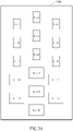
- FIG 3A illustrates a prior art electrode array 148 having 16 electrodes “E-1” to “E-16.”
- the electrode array 140 may be implemented using the electrode array 148.
- Prior art stimulators allow a user (e.g., a clinician) to divide the electrodes "E-1" to "E-16" into up to four groups. Each group may include any number of electrodes. Stimulation having different frequency and pulse width may be delivered to the groups.
- the neurostimulator device 120 may divide the electrodes "E-1" to "E-16” into any number of groups. For example, each electrode may be assigned to its own group. By way of another example, one or more electrodes may belong to multiple groups. Table A below provides a few examples of groups that may be identified and stimulated independently.
- Electrodes function as the anode and which function as a cathode are also specified for illustrative purposes.
- Table A Group Number Anode electrodes Cathode electrodes 1 1 3 2 1 and 2 3, 4, 5, and 6 3 1, 2, and 3 13, 16, and 15 4 1, 2, and 3 6, 7, 8, and 9
- prior art stimulators are configured to deliver only rectangular waves to the electrodes "E-1" to “E-16.”
- the neurostimulator device 120 is configured to deliver stimulation having waveform shapes beyond merely rectangular waves.
- the neurostimulator device 120 is configured to deliver stimulation to a single selected one of the electrodes 142 and/or use a single selected one of the electrodes 142 as a reference electrode.
- Prior art stimulators are not capable of this level of addressability.
- the electrode array 140 may be constructed using microfabrication technology to place numerous electrodes in an array configuration on a flexible substrate.
- One suitable epidural array fabrication method was first developed for retinal stimulating arrays (see, e.g., Maynard, Annu. Rev. Biomed. Eng., 3: 145-168 (2001 ); Weiland and Humayun, IEEE Eng. Med. Biol. Mag., 24(5): 14-21 (2005 )), and U.S. Patent Publications 2006/0003090 and 2007/0142878 .
- the stimulating arrays comprise one or more biocompatible metals (e.g., gold, platinum, chromium, titanium, iridium, tungsten, and/or oxides and/or alloys thereof) disposed on a flexible material (e.g., parylene A, parylene C, parylene AM, parylene F, parylene N, parylene D, or other flexible substrate materials).
- biocompatible metals e.g., gold, platinum, chromium, titanium, iridium, tungsten, and/or oxides and/or alloys thereof
- a flexible material e.g., parylene A, parylene C, parylene AM, parylene F, parylene N, parylene D, or other flexible substrate materials.
- Parylene has the lowest water permeability of available microfabrication polymers, is deposited in a uniquely conformal and uniform manner, has previously been classified by the FDA as a United States Pharmacopeia (USP) Class VI biocompatible material (enabling its use in chronic implants) ( Wolgemuth, Medical Device and Diagnostic Industry, 22(8): 42-49 (2000 )), and has flexibility characteristics (Young's modulus ⁇ 4 GPa ( Rodger and Tai, IEEE Eng. Med. Biology, 24(5): 52-57 (2005 ))), lying in between those of PDMS (often considered too flexible) and most polyimides (often considered too stiff).
- USP United States Pharmacopeia
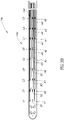
- the electrode array 140 may be characterized as being a microelectromechanical systems ("MEMS") device. While the implementation of the electrode array 140 illustrated in Figure 3 may be suited for use in animals, the basic geometry and fabrication technique can be scaled for use in humans.
- the electrode array 140 is configured for implantation along the spinal cord 110 (see Figure 1 ) and to provide electrical stimulation thereto. For example, the electrode array 140 may provide epidural stimulation to the spinal cord 110.
- the electrode array 140 allows for a high degree of freedom and specificity in selecting the site of stimulation compared to prior art wire-based implants, and triggers varied biological responses that can lead to an increased understanding of the spinal cord 110 and improved neurological function in the subject 102.
- Electrode array 140 A non-limiting example of an electrode array that may be used to construct the electrode array 140 is described in co-pending U.S. Patent Application No. 13/356,499, filed on January 23, 2012 , and titled Parylene-Based Microelectrode Array Implant for Spinal Cord Stimulation.
- the electrode array 140 includes a plurality of electrodes 142 (e.g., electrodes A1-A9, B1-B9, and C1-C9), and a plurality of electrically conductive traces 144.
- the electrodes 142 may vary in size, and be constructed using a biocompatible substantially electrically conductive material (such as platinum, Ag/AgCI, and the like), embedded in or positioned on a biocompatible substantially electrically non-conductive (or insulating) material (e.g., flexible parylene).
- One or more of the traces 144 is connected to each of the electrodes 142. Connecting more than one of the traces 144 to each of the electrodes 142 may help ensure signals reach and are received from each of the electrodes 142.
- Each of the electrodes 142 has one or more electrically conductive contacts (not shown) positionable alongside body tissue.
- the body tissue may include neurological tissue (e.g., the spinal cord 110, one or more spinal nerves, one or more nerve roots, one or more peripheral nerves, the brain stem, and/or the brain 108, and the like), other types of spinal tissue (e.g., the dura of the spinal cord 110), and the tissue of end organs.
- the electrode array 140 may be configured to be positionable alongside such body tissue.
- the electrode array 140 may be implanted using any of a number of methods (e.g., a laminectomy procedure) well known to those of skill in the art.
- the electrodes 142 may be implanted epidurally along the spinal cord 110 (see Figure 1 ).
- the electrodes 142 may be positioned at one or more of a lumbosacral region, a cervical region, and a thoracic region of the spinal cord 110 (see Figure 1 ).
- the electrodes 142 are positioned distal to the lesion 112 (see Figure 1 ) relative to the brain 108 (see Figure 1 ). In other words, the electrodes 142 are positioned farther from the brain 108 than the lesion 112.
- the one or more leads 130 illustrated include electrically conductive elements.
- the one or more leads 130 include an electrically conductive element for each of the traces 144 of the electrode array 140.
- the one or more leads 130 include an electrically conductive element for each of the electrodes 142 of the electrode array 140.
- the one or more leads 130 of the assembly 100 connect the neurostimulator device 120 to the traces 144 of the electrode array 140, which are each connected to one of the electrodes 142.
- a signal generated by the neurostimulator device 120 is transmitted via the one or more leads 130 to selected ones of the traces 144, which transmit the signal to selected ones of the electrodes 142, which in turn deliver the stimulation to the body tissue in contact with the electrically conductive contacts (not shown) of the electrodes 142.
- the one or more leads 130 may vary in length.
- the electrically conductive elements may be constructed using a biocompatible substantially electrically conductive material (such platinum, Ag/AgCI, and the like), embedded in or surrounded by a biocompatible substantially electrically non-conductive (or insulating) material (e.g., flexible parylene).
- the one or more leads 130 may include one or more connectors 132 and 134. In the embodiment illustrated, the connector 132 is used to connect the one or more leads 130 to the electrode array 140 and the connector 134 is used to connect the one or more leads 130 to the neurostimulator device 220.
- Prior art epidural stimulating impulse generators cannot generate a complex pattern of stimulating signals needed to produce improved neurological function (e.g., stepping, standing, arm movement, and the like after a severe SCI or/and occurrence of a neuromotor disorders).
- an alternating spatiotemporal electric field having oscillations that peak over the right side of the spinal cord 110 (e.g., in the lumbosacral region) during a right leg swing phase, and oscillations that peak over the left side of the spinal cord 110 (e.g., in the lumbosacral region) during the left swing phase may be used.
- a rostral-caudal gradient in both electrode voltage and electrode stimulation frequency may be used. Rostral is nearer the brain 108 and caudal farther from the brain 108. Prior art stimulators are simply not configured to deliver such complex stimulation patterns.
- Prior art epidural stimulating impulse generators have other limitations that limit their ability to help patients recover functionality lost as a result of the neurologically derived paralysis.
- typical prior art stimulators deliver stimulation having the same amplitude to all active electrodes.
- Some prior art stimulators are configured to deliver stimulation having different amplitudes to four different groups of electrodes.
- typical prior art stimulators deliver stimulation having the same frequency to all channels (or electrodes).
- Some prior art stimulators are configured to deliver stimulation having different frequencies to four groups of channels (or electrodes).
- typical prior art stimulators deliver stimulation having the same pulse width to all of the channels (or electrodes).
- typical prior art stimulators lack the ability to generate non-pulse waveforms.
- a more complex waveform than the type generated by prior art stimulators must be delivered to one or more target locations.
- non-rectangular waveforms e.g., waveform 160 illustrated in Figure 4A
- small "prepulses” e.g., prepulse 162 illustrated in Figure 4B
- main "driving" pulse e.g., driving pulse 164 illustrated in Figure 4B
- the timing of the onset of electrical stimulation must be carefully controlled.
- the spatio-temporal characteristics of the stimulating voltage fields needed for stepping require the ability to specify and control the phase shift (the exact timing of the onset of the stimulating waveform) between the electrodes 142, across the entire electrode array 140.
- Prior art stimulators lack this ability.
- the neurostimulator device 120 is configured to generate complex types and patterns of electrical stimulation that achieve improved neurological function.
- the neurostimulator device 120 is configured to generate (and deliver to the electrode array 140) one or more "complex stimulation patterns."
- a complex stimulation pattern has at least the following properties:
- the neurostimulator device 120 delivers the complex stimulation pattern to the electrode array 140.
- the electrode array 140 is configured such that which of the electrodes 142 will receive stimulation may be selected.
- the electrodes 142 are individually addressable by the neurostimulator device 120.
- the neurostimulator device 120 may also be configured such that the frequency, waveform width (or period), and/or amplitude of the stimulation delivered to each of the selected ones of the electrodes 142 may also be adjustable.
- the complex stimulation pattern may remain constant, repeat, or change over time.
- the configurability of the complex stimulation patterns delivered by the neurostimulator device 120 (by changing the stimulation parameters) enables the identification of effective complex stimulation patterns and the adjustment of the complex stimulation patterns to correct for migration and/or initial surgical misalignment.
- the neurostimulator device 120 may be configured to deliver a plurality of different complex stimulation patterns to the electrodes 142.
- the neurostimulator device 120 is programmable (e.g., by the subject 102 or a physician).
- the neurostimulator device 120 may be programmed with stimulation parameters and/or control parameters configured to deliver a complex stimulation pattern that is safe, efficacious, and/or selected to target specific body tissue. Further, stimulation parameters and/or control parameters may be customized for each patient (e.g., based on response to pre-surgical (implant) evaluation and testing).
- the neurostimulator device 120 may have a variable activation control for providing a complex stimulation pattern either intermittently or continuously, and allowing for adjustments to frequency, waveform width, amplitude, and duration.
- the neurostimulator device 120 may be used to (a) generate or maintain efficacious and/or optimal complex stimulation patterns, and/or (b) adjust the location of the application of stimulation (relative to the neural tissue) when the assembly 100 migrates and/or was misaligned during implantation.
- the neurostimulator device 120 may be configured to store, send, and receive data.
- the data sent and received may be transmitted wirelessly (e.g., using current technology, such as Bluetooth, ZigBee, FCC-approved MICS medical transmission frequency bands, and the like) via a wireless connection 155 (see Figure 2 ).
- the neurostimulator device 120 may be configured to be regulated automatically (e.g., configured for open loop and/or closed loop functionality). Further, the neurostimulator device 120 may be configured to record field potentials detected by the electrodes 142, such as somatosensory evoked potentials (SSEPs) generated by the dorsum of the spinal cord 110.
- the neurostimulator device 120 may be configured to be rechargeable.
- the neurostimulator device 120 may be configured with one or more of the following properties or features:
- the neurostimulator device 120 may be connected to one or more sensors 188 (e.g., Electromyography ("EMG") sensors 190, joint angle (or flex) sensors 191, accelerometers 192, gyroscopic sensors, pressure sensors, flow sensors, load sensors, and the like) via connections 194 (e.g., wires, wireless connections, and the like).
- the connections (e.g., the connections 194) and sensors 188 may be implemented using external components and/or implanted components.
- the neurostimulator device 120 may be configured to modify or adjust the complex stimulation pattern based on information received from the sensors 188 via the connections 194.
- the connections 194 may implemented using wired or wireless connections.
- the neurostimulator device 120 may be connected to reference wires 196.
- one of the reference wires 196 is positioned near the shoulder, the other of the reference wires 196 is positioned in the lower back.
- this is not a requirement.
- the connections 194 may include one or more connectors 136 and 138.
- the connector 136 is used to connect the connections 194 to the sensors 188 and the connector 138 is used to connect the connections 194 to the neurostimulator device 220.
- the neurostimulator device 120 may be approximately 20 mm to approximately 25 mm wide, approximately 45 mm to approximately 55 mm long, and approximately 4 mm to approximately 6 mm thick.
- the neurostimulator device 120 may be approximately 3 mm to approximately 4 mm wide, approximately 20 mm to approximately 30 mm long, and approximately 2 mm to approximately 3 mm thick.
- the electrodes 142 are positioned on or near a target area (e.g., distal the lesion 112 illustrated in Figure 1 ). If the subject 102 (see Figure 2 ) has a SCI, the electrode array 140 may be positioned along the spinal cord 110 in a target area that is just distal to a margin of the lesion 112. Thus, if the paralysis was caused by SCI at a first location along the spinal cord 110 (see Figure 1 ), the electrodes 142 may be implanted (e.g., epidurally) at a second location below the first location along the spinal cord relative to the subject's brain 108. The electrodes 142 may be placed in or on the spinal cord 110 (see Figure 1 ), one or more spinal nerves, one or more nerve roots, one or more peripheral nerves, the brain stem, and/or the brain 108 (see Figure 1 ).
- the complex stimulation pattern may include at least one of tonic stimulation and intermittent stimulation.
- the stimulation applied may be pulsed.
- the electrical stimulation may include simultaneous or sequential stimulation of different regions of the spinal cord 110, one or more spinal nerves, one or more nerve roots, one or more peripheral nerves, the brain stem, and/or the brain 108 (see Figure 1 ).
- the complex stimulation pattern applied by the assembly 100 may be below the second stimulation threshold such that the at least one selected spinal circuit is at least partially activatable by the addition of neurological signals (e.g., neurological signals induced by physical training or neurological signals originating from the brain 108) generated by the subject 102 (see Figure 2 ).
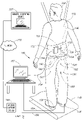
- neurological signals generated by the subject 102 may be induced by subjecting the subject to physical activity or training (such as stepping on a treadmill 170 while suspended in a harness 172 or other support structure).
- the neurological signals generated by the subject 102 may be induced in a paralyzed portion of the subject 102.
- the neurological signals generated by the subject 102 may include supraspinal signals (or neurological signals originating from the brain 108).
- the embodiment of the assembly 100 illustrated in Figure 1 is configured for implantation in the subject 102 (see Figure 2 ).
- embodiments may be constructed for use with other subjects, such as other mammals, including rats.
- the assembly 100 may be configured for chronic implantation and use.
- the assembly 100 may be used to stimulate one or more nerve roots, one or more nerves, the spinal cord 110 (see Figure 1 ), the brain stem, and/or the brain over time.
- the implantable assembly 100 may be used with an external system 180 illustrated in Figure 2 .
- the external system 180 includes an external control unit 150 that may be used program, gather data, and/or charge the neurostimulator device 120 (e.g., via a wireless connection 155).
- the external control unit 150 is configured to be handheld.
- the external system 180 includes a computing device 152 described in detail below.
- the external control unit 150 may connected via a connection 154 (e.g., a USB connection, wireless connection, and the like) to an external computing device 152.
- the computing device 152 may be connected to a network 156 (e.g., the Internet) and configured to send and receive information across the network to one or more remote computing devices (e.g., a remote computing device 157).
- a network 156 e.g., the Internet
- remote computing devices e.g., a remote computing device 157
- the external control unit 150 may be omitted and the computing device 152 may communicate instructions directly to the neurostimulator device 120 via the wireless connection 155.
- the computing device 152 may be implemented as a cellular telephone, tablet computing device, and the like having a conventional wireless communication interface.
- the computing device 152 may communicate instructions to the neurostimulator device 120 using a wireless communication protocol, such as Bluetooth.
- the computing device 152 may receive data from the neurostimulator device 120 via the wireless connection 155. Instructions and data may be communicate to and received from the remote computing device 157 over the network 156.
- the remote computing device 157 may be used to remotely program the neurostimulator device 120 (via the computing device 152) over the network 156.
- One or more external sensors 158 may be connected to the computing device 152 via (wired and/or wireless) connections 159. Further, a motion capture system 166 may be connected to the computing device 152. The external sensors 158 and/or motion capture system 166 may be used to gather data about the subject 102 for analysis by the computing device 152 and/or the neurostimulator device 120.
- the external sensors 158 may include at least one of the following: foot pressure sensors, a foot force plate, in-shoe sensors, accelerometers, surface EMG sensors, gyroscopic sensors, and the like.
- the external sensors 158 may be attached to or positioned near the body of the subject 102.
- the motion capture system 166 may include any conventional motion capture system (e.g. a video-based motion capture system) and the present teachings are not limited to use with any particular motion capture system.
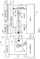
- FIG. 5 is a block diagram of a first embodiment of a system 200.
- the system 200 includes an implantable assembly 202 substantially similar to the assembly 100 described above, and an external system 204 substantially similar to the external system 180 described above. Therefore, only components of the assembly 202 that differ from those of the assembly 100, and components of the external system 204 that differ from those of the external system 180 will be described in detail. For ease of illustration, like reference numerals have been used to identify like components in Figures 1-3 and 5 .
- the assembly 202 includes a neurostimulator device 220, the one or more leads 130, and the electrode array 140, and the connections 194.
- the assembly 202 may also include the reference wires 196 (see Figure 2 ).
- the assembly 202 may include the two reference wires illustrated in Figure 2 .
- the connections 194 include sixteen wires, each connected to a different one of the sensors 188 (e.g., the EMG sensors 190).
- this is not a requirement and embodiments may be constructed using a different number of connections (e.g., wires), a different number of sensors, and/or different types of sensors without departing from the scope of the present teachings.
- the electrode array 140 includes the 27 electrodes A1-A9, B1-B9, and C1-C9.
- Particular embodiments include at least 16 electrodes.
- the neurostimulator device 220 is configured to send a stimulating signal (e.g., a "pulse") to any of the electrodes 142 in the electrode array 140.
- the neurostimulator device 220 is also configured to switch between different electrodes very rapidly.
- the neurostimulator device 220 can effectively send a predefined pattern of pulses to selected ones of the electrodes 142 in the electrode array 140.
- the neurostimulator device 220 is configured to generate a wide variety of waveforms such that virtually any pulsed waveform can be generated.
- the electrodes 142 may be arranged in more than four groups, each group including one or more of the electrodes. Further, an electrode may be included in more than one group. In groups including more than one electrode, the electrodes may be stimulated simultaneously.
- the wireless connection 155 may be two components, a communication connection 155A and a power transfer connection 155B.
- the neurostimulator device 220 may be configured to deliver stimulation having the following properties:
- the neurostimulator device 220 includes a multiplexer sub-circuit 230, a stimulator circuit 240, a controller 250 (connected to a controller circuit 252 illustrated in Figure 8 ), and an optional wireless power circuit 260.
- the controller 250 sends three control signals Clock, Data, and EN to the multiplexer sub-circuit 230, and receives data A1'-A4' from the multiplexer sub-circuit 230.
- the stimulator circuit 240 provides a first stimulation signal STIM+ and a second stimulation signal STIM- to the multiplexer sub-circuit 230.
- the controller 250 sends control signals PWM and MODE to the stimulator circuit 240.
- the control signal MODE sent by the controller 250 to the stimulator circuit 240 instructs the stimulator circuit 240 to operate in either constant voltage mode or constant current mode.
- the control signal PWM sent by the controller 250 to the stimulator circuit 240 uses pulse-width modulation to control power sent by the stimulator circuit 240 to the multiplexer sub-circuit 230 as the first and second stimulation signals STIM+ and STIM-.
- the control signal PWM configures at least a portion of the complex stimulation pattern.
- the multiplexer sub-circuit 230 determines which of the electrodes 142 and/or connections 194 receives the stimulation. Therefore, the multiplexer sub-circuit 230 configures at least a portion of the complex stimulation pattern.
- both the stimulator circuit 240 and the multiplexer sub-circuit 230 configure the complex stimulation pattern based on instructions received from the controller 250.
- the controller 250 is connected wirelessly to the external programming unit 150 via the communication connection 155A.
- the communication connection 155A may be configured to provide bi-directional wireless communication over which the controller 250 may receive system control commands and data from the external programming unit 150, as well as transmit status information and data to the external programming unit 150.
- the communication connection 155A may include one or more analog communication channels, one or more digital communication channels, or a combination thereof.
- the controller 250 receives power (e.g., 3V) from the wireless power circuit 260 and a power monitoring signal PWRMON from the wireless power circuit 260.
- the wireless power circuit 260 provides power (e.g., 12V and 3V) to the multiplexer sub-circuit 230.
- the wireless power circuit 260 also provides power (e.g., 12V and 3V) to the stimulator circuit 240.
- the wireless power circuit 260 receives power wirelessly from the external programming unit 150 via the power transfer connection 155B.
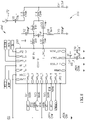
- Figures 6A and 6B are a circuit diagram of an exemplary implementation of the multiplexer sub-circuit 230.
- Figure 6A is a leftmost portion of the circuit diagram of the multiplexer sub-circuit 230
- Figure 6B is a rightmost portion of the circuit diagram of the multiplexer sub-circuit 230.
- the circuit diagram of Figures 6A and 6B includes amplifiers AMP1-AMP4, shift registers SR1-SR4 (e.g., implemented using NXP Semiconductors 74HC164), and analog multiplexer chips M0-M9.
- the amplifiers AMP1-AMP4 output the data A1'-A4', respectively.
- the amplifiers AMP1-AMP4 e.g., Analog Devices AD8224
- the amplifiers AMP1-AMP4 may be implemented as differential amplifiers with a gain set to 200. However, as is apparent to those of ordinary skill in the art, other gain values may be used. Further, the gains of the amplifiers AMP1-AMP4 may be readily changed by modifications to the components known to those of ordinary skill in the art.
- the multiplexer sub-circuit 230 routes the first and second stimulation signals Stim+ and Stim- to the selected ones of the electrodes 142 and/or connections 194.
- the multiplexer sub-circuit 230 also routes signals received from selected ones of the electrodes 142 and/or connections 194 to the amplifiers AMP1-AMP4.
- the multiplexer sub-circuit 230 is configured to route signals between the stimulator circuit 240, the amplifiers AMP1-AMP4, the electrodes 142, and the connections 194.
- the controller 250 sends a 30-bit serial data stream through the control signals Clock and Data to the multiplexer sub-circuit 230, which is fed into the shift registers SR1-SR4.
- the shift registers SR1-SR4 in turn control the analog multiplexer chips M0-M9, which are enabled by the control signal EN.
- the multiplexer chip M0 has inputs "Da” and "Db” for receiving the first and second stimulation signals STIM+ and STIM-, respectively, from the controller 250.
- the multiplexer chip M0 is used to disconnect one or more of the electrodes 142 and/or one or more of the sensors 188 (e.g., the EMG sensors 190) during recording of signals detected by the disconnect component(s).
- the multiplexer chip M0 is also used to select a polarity (or tristate) for each of the electrodes 142 when stimulation is applied.
- the multiplexer chip M0 may be implemented as a 2x(4:1) multiplexer (e.g., Analog Devices ADG1209).
- the multiplexer chips M1-M9 are interconnected to connect almost any pair of the electrodes 142 or connections 194 to the amplifier AMP1 and the inputs "Da" and "Db" (which receive the first and second stimulation signals STIM+ and STIM-, respectively) of multiplexer chip M0.
- the multiplexer chips M1-M9 may each be implemented using an 8:1 multiplexer (e.g., Analog Devices ADG1208).
- a label in each rectangular tag in the circuit diagram identifies a connection to one of the electrodes 142 or connections 194.
- Each label in a rectangular tag starting with the letter “E” identifies a connection to one of the connections 194 connected to one of the sensors 188 (e.g., one of the EMG sensors 190).
- the label "E1+” adjacent multiplexer chip M1 identifies a connection to a first wire
- the label "E1-” adjacent multiplexer chip M2 identifies a connection to a second wire.
- the labels "E1+” and "E1-” identify connections a first pair of the connections 194.
- the labels "G1" and “G2" adjacent multiplexer chip M9 identify connections to the reference wires 196 (see Figure 2 ).
- Each label in a rectangular tag starting with a letter other than the letter “E” or the letter “G” identifies a connection to one of the electrodes 142.
- the label “A3” refers to a connection to the electrode A3 (see Figure 3 ) in column A and row 3 (where column A is leftmost, column B is in the middle, column C is rightmost, row 1 is rostral, and row 9 is caudal).
- some key electrodes may have more than one connection to the multiplexer sub-circuit 230.
- the electrodes A1, B1, C1, A9, B9, and C9 are each identified by more than one label.
- the multiplexer sub-circuit 230 is designed to operate in four modes. In a first mode, the multiplexer sub-circuit 230 is configured to select an individual electrode to which to apply a monopolar stimulating pulse. In a second mode, the multiplexer sub-circuit 230 is configured to select a pair of the electrodes 142 to stimulate in a bipolar fashion. In a third mode, the multiplexer sub-circuit 230 is configured to select a single electrode from which to record, with the recorded waveform referenced to a ground signal. In a fourth mode, the multiplexer sub-circuit 230 is configured to select a pair of of the electrodes 142 from which to record in a differential fashion.
- the neurostimulator device 220 can provide selective stimulation to any of the electrodes 142.
- the multiplexer sub-circuit 230 is configured to route stimulation between almost any pair of the electrodes 142 or the connections 194.
- the electrode A1 may be the anode and the electrode B6 the cathode.
- the multiplexer sub-circuit 230 is configured route signals received from the connections 194 to the amplifiers AMP1-AMP4 and to the controller 250 (in data A1'-A4') for recording thereby. Similarly, the multiplexer sub-circuit 230 is configured route signals received from the electrodes 142 to the amplifiers AMP1-AMP4 and to the controller 250 (in data A1'-A4') for recording thereby. By way of a non-limiting example, the multiplexer sub-circuit 230 may be configured route signals received from four electrodes positioned in the same column (e.g.
- Electrodes A1, A3, A5, and A7 and signals received from a fifth electrode e.g., electrode A9 positioned in the same column to the controller 250 (in data A1'-A4' output by the amplifiers AMP1-AMP4) so that a differential signal received from the first four relative to the fifth may be recorded by the controller 250 for each pair of electrodes (e.g., a first pair including electrodes A1 and A9, a second pair including electrodes A3 and A9, a third pair including electrodes A5 and A9, and a fourth pair including electrodes A7 and A9).
- the multiplexer sub-circuit 230 receives power (e.g., 12V and 3V) from the wireless power circuit 260.
- power lines providing this power to the multiplexer sub-circuit 230 have been omitted.
- the power lines may be implemented using one line having a voltage of about +12V, one line having a voltage of about +2V to about +6V (e.g., +3V), and one ground line.
- the multiplexer sub-circuit 230 may be configured to change configurations in less than one microsecond in embodiments in which the control signals Clock and Data are fast enough. This allows the first and second stimulation signals Stim+ and Stim- (received from the stimulator circuit 240) to be delivered in short pulses to selected ones of the electrodes 142 in about one millisecond and also allows the amplifiers AMP1-AMP4 to rapidly switch input signals so the controller 250 may effectively record from 8 or 16 signals (instead of only four) within as little as about 20 microseconds. In some embodiments, the controller 250 may effectively record from 8 or 16 signals (instead of only four) within as little as 5 microseconds.
- FIG 7 is a circuit diagram of an exemplary implementation of the stimulator circuit 240.
- the stimulator circuit 240 is configured to selectively operate in two modes: constant voltage mode and constant current mode.
- labels “Mode1” and “Mode2” identify connections to pins “P1_0" and “P1_1,” respectively, of the controller 250 (see Figure 8 ).
- pin “P1_0” (connected to the connection labeled “Model") is set to ground and pin “P1_1” (connected to the connection labeled "Mode2”) is high impedance
- the stimulator circuit 240 is in constant voltage mode.
- pin “P1_1” (connected to the connection labeled "Mode2”) is set to ground and pin “P1_0” (connected to the connection labeled "Model”) is high impedance
- the stimulator circuit 240 is in constant current mode.
- FIG 8 is a circuit diagram of an exemplary implementation of a controller circuit 252 that includes the controller 250 and its surrounding circuitry.
- the controller 250 controls the multiplexer sub-circuit 230, records amplified signals received (in the data A1'-A4') from the multiplexer sub-circuit 230, and monitors wireless power (using the power monitoring signal PWRMON received from the wireless power circuit 260).
- the controller 250 also communicates with an external controller 270.
- the controller 250 has been implemented using a Texas Instruments CC1110.
- controller 250 is implemented using a different microcontroller, a microprocessor, a Field Programmable Gate Array (“FPGA”), a Digital Signal Processing (“DSP”) engine, a combination thereof, and the like.
- FPGA Field Programmable Gate Array
- DSP Digital Signal Processing
- the controller circuit 252 is configured to record voltages and currents received from the electrode array 140 when it is not stimulated. In such embodiments, the controller circuit 252 is also configured to transmit the recorded data over the communication connection 155A (e.g., in "real time") to the external programming unit 150. In the embodiment illustrated, the controller circuit 252 includes an antenna 272 configured to communicate with the external controller 270. The controller circuit 252 may be configured to coordinate stimulating (signal sending) and reading (signal receiving) cycles with respect to the electrode array 140.
- signals e.g., Motor Evoked Potentials (MEPs)
- MEPs Motor Evoked Potentials
- the controller circuit 252 may be configured to measure (and/or control) the exact timing of the onset of stimulation.
- the controller circuit 252 may be configured to reset or stop stimulation at a desired time.
- the controller circuit 252 may be configured to transition smoothly between successive stimulation (e.g., pulses) and successive stimulation patterns.
- the controller circuit 252 may be configured to monitor electrode impedance, and impedance at the electrode/tissue interface. Of particular concern is impedance at relatively low frequencies (e.g., 10-1000 Hz).
- the controller circuit 252 may be configured to limit current and voltage. Further, the controller circuit 252 may be configured to trigger an alarm (or send an alarm message to the computing device 152) when voltage or current limits are exceeded.
- the neurostimulator device 220 may shut down or power down if an unsafe condition is detected.
- the external controller 270 may be used to program the controller 250.
- the external controller 270 may be a component of the external control unit 150 (see Figure 2 ).
- the external controller 270 may be implemented using a Texas Instruments CC1111.
- the external controller 270 may relay information to and from the computing device 152 through the connection 154 (e.g., a USB connection, and/or a wireless connection).
- the computing device 152 may be configured to control data streams to be sent to the neurostimulator device 220.
- the computing device 152 may interpret data streams received from the neurostimulator device 220.
- the computing device 152 is configured to provide a graphical user interface for communicating with the neurostimulator device 220.
- the user interface may be used to program the neurostimulator device 220 to deliver particular stimulation. For example, the user interface may be used to queue up a particular sequence of stimuli.
- the computing device 152 may execute a method (e.g., a machine learning method described below) configured to determine stimulation parameters.
- the user interface may be used to configure the method performed by the computing device 152.
- the user interface may be used to transfer information recorded by the neurostimulator device 220 to the computing device 152 for storage and/or analysis thereby.
- the user interface may be used to display information indicating an internal system state (such the current selection of stimulation parameters values) and/or mode of operation (e.g., constant voltage mode, constant current mode, and the like).
- FIG. 9 is a circuit diagram of an exemplary implementation of the optional wireless power circuit 260.
- the wireless power circuit 260 is configured to receive power wirelessly from an external wireless power circuit 280.
- the wireless power circuit 260 may supply both about 3V DC (output VCC) and about 12V DC (output VDD).
- the output VCC is connected to the multiplexer sub-circuit 230, the stimulator circuit 240, and the controller 250, and the output VDD is connected to the multiplexer sub-circuit 230 and the stimulator circuit 240.
- the external wireless power circuit 280 may be a component of the external control unit 150 (see Figure 2 ).
- the external wireless power circuit 280 may be implemented using a Class E amplifier and configured to provide variable output.
- the external wireless power circuit 280 provides power to the wireless power circuit 260 via inductive coupling over the power transfer connection 155B.
- the wireless power circuit 260 may include a radio frequency ("RF") charging coil 264 and the external wireless power circuit 280 includes an RF charging coil 284 configured to transfer power (e.g., inductively) to the RF charging coil 264.
- RF radio frequency
- communication channels may be multiplexed on the wireless transmission.
- the wireless power circuit 260 may be connected to one or more rechargeable batteries (not shown) that are chargeable using power received from the external wireless power circuit 280.
- the batteries may be implemented using rechargeable multi-cell Lithium Ion Polymer batteries.
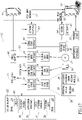
- FIG 10 is a block diagram of an implantable assembly 300.
- the assembly 300 may be configured to communicate with the external controller 270 via the communication connection 155A.
- the assembly 300 may receive power wirelessly from the external wireless power circuit 280 via inductive coupling over the power transfer connection 155B.
- the assembly 300 is configured to also provide electrical stimulation directly to muscles (not shown) that will cause the muscle to move (e.g., contract) to thereby augment the improved neurological function provided by the complex stimulation patterns alone.
- the assembly 300 is configured to provide one or more complex stimulation patterns to 16 or more individually addressable electrodes for purposes of providing improved neurological function (e.g., improved mobility recovery after SCI).
- the assembly 300 includes a neurostimulator device 320, the one or more leads 130, and the electrode array 140, the connections 194 (connected to the sensors 188), and connections 310 (e.g., wires, wireless connections, and the like) to (implanted and/or external) muscle electrodes 312.
- the assembly 300 may also include the reference wires 196 (see Figure 2 ).
- the assembly 300 may include the two reference wires illustrated in Figure 2 .
- the connections 194 include sixteen wires, each connected to a different one of the sensors 188 (e.g., the EMG sensors 190).
- this is not a requirement and embodiments may be constructed using a different number of wires, a different number of EMG sensors, and/or different types of sensors without departing from the scope of the present teachings.
- the neurostimulator device 320 includes a controller 322, a recording subsystem 330, a monitor and control subsystem 332, a stimulating subsystem 334, a muscle stimulator drive 336, a sensor interface 338, a wireless communication interface 340, an RF power interface 342, and at least one power source 344 (e.g., a rechargeable battery).
- the controller 322 has been implemented using a microcontroller (e.g., a Texas Instruments CC1110).
- a microcontroller e.g., a Texas Instruments CC1110
- embodiments may be constructed in which the controller 250 is implemented using a microprocessor, FPGA, DSP engine, a combination thereof, and the like.
- the recording subsystem 330 is configured to record electrical signals received from one or more of the electrodes 142 in the electrode array 140.
- the electrodes used to record may be the same electrodes used to provide the complex stimulation pattern, or different electrodes specialized for recording.
- the recording subsystem 330 may be connected (directly or otherwise) to one or more of the leads 130. In the embodiment illustrated, the recording subsystem 330 is connected to the leads 130 via the monitor and control subsystem 332.
- the recording subsystem 330 includes one or more amplifiers 346.
- the amplifiers 346 are implemented as low noise amplifiers ("LNAs”) with programmable gain.
- LNAs low noise amplifiers
- the monitor and control subsystem 332 illustrated includes a blanking circuit 350 that is connected directly to the leads 130.
- the blanking circuit 350 is configured to disconnect the recording subsystem 330 (which is connected thereto) from the leads 130 when the complex stimulation pattern is applied to the electrodes 142 to avoid damaging the amplifiers 346.
- Bidirectional control and status lines (not shown) extending between the blanking circuit 350 and the controller 340 control the behavior of the blanking circuit 350.
- the monitor and control subsystem 332 monitors the overall activity of the neurostimulator device 320, as well as the functionality (e.g., operability) of the electrode array 140.
- the monitor and control subsystem 332 is connected to the CPU by bidirectional digital and analog signal and control lines 352.
- the monitor and control subsystem 332 includes a circuit 354 configured to monitor electrode impedance.
- a multiplexer (not shown) may be connected to the leads 130, allowing the monitor and control subsystem 332 to selectively interrogate the signal received from each electrode.
- the output of the multiplexer (not shown) is connected to an A/D circuit (not shown), so that a signal received from a selected one of the electrodes 142 can be digitized, and transmitted to the controller 322 to assess the functionality of the stimulating circuitry.
- the monitor and control subsystem 332 may include circuitry 356 configured to assess the functionality (e.g., operability) of the power source 344.
- the amplifiers 346 receive signals from the leads 130 when the blanking circuit 350 is in the off state. In some embodiments, a different one of the amplifiers 346 is connected to each different one of the leads 130. In other embodiments, the blanking circuit 350 includes or connected to a multiplexing circuit having an input is connected to the leads 130 and the output of the blanking system 350. In such embodiments, the multiplexing circuit routes an electrode signal (selected by the controller 322) to a single one of the amplifiers 346. The amplifiers 346 are connected to the controller 322 via bidirectional control and status lines (not shown) that allow the controller 322 to control the gain and behavior of the amplifiers 346.
- the recording subsystem 330 includes an analog-to-digital ("A/D") circuit 347 that digitizes the output(s) received from the amplifiers 346.
- A/D analog-to-digital
- a separate A/D circuit is dedicated to the output of each amplifiers 346.
- a multiplexing circuit (not shown) routes the output of a selected one of the amplifiers 346 to a single A/D circuit.
- the output of the A/D circuit 347 is connected via a serial or parallel digital bus 348 to the controller 322.
- the recording subsystem 330 includes a parallel to serial circuit 349 that serializes the output received from the A/D circuit 347 for transmission on the bus 348. Control and status lines (not shown) connect the A/D circuit 347 to the controller 322, allowing the controller 322 to control the timing and behavior of the A/D circuit 347.
- the stimulating subsystem 334 will be described as delivering complex stimulation patterns over channels. Each channel corresponds to one of the electrodes 142. Stimulation delivered over a channel is applied to the corresponding one of the electrodes 142. Similarly, stimulation received from one of the electrodes 142 may be received over the corresponding channel. However, in some embodiments, two or more electrodes may be physically connected to the same channel so their operation is governed by a single channel.
- the stimulating subsystem 334 is configured to generate complex stimulation patterns, which as explained above include complex waveforms (either in voltage or current mode), and deliver the stimulation on each of one or more of the channels.
- the stimulating subsystem 334 is connected to the controller 322 by multiple bidirectional lines 360 over which the stimulating subsystem 334 receives commands and stimulating waveform information.
- the stimulating subsystem 334 may transmit circuit status information to the controller 322 over the lines 360.
- Each output is connected to one of the leads 130, thereby stimulating a single one of the electrodes 142 in the electrode array 140.
- the stimulating subsystem 334 includes a digital-to-analog amplifier 362 that receives stimulating waveform shape information from the controller 322.
- the amplifier 362 turn drives (voltage or current) amplifiers 364.
- the outputs of the amplifiers 364 are monitored and potentially limited by overvoltage or over-current protection circuitry 366).
- the muscle stimulator drive 336 is configured to drive one or more of the muscle electrodes 312. Alternatively, the muscle stimulator drive 336 may provide an interface to a separate drive system (not shown).
- the muscle stimulator drive 336 is connected by bidirectional control lines 368 to the controller 322 to control the operation of the muscle stimulator drive 336.
- the sensor interface 338 interfaces with one or more of the sensors 188 (the EMG sensors190, joint angle sensors 191, accelerometers 192, and the like). Depending upon the implementation details, the sensor interface 338 may include digital signal inputs (not shown), low noise amplifiers (not shown) configured for analog signal line inputs, and analog inputs (not shown) connected to A/D circuits (not shown).
- the controller 322 may be connected wirelessly to the external programming unit 150 via the communication connection 155A.
- the communication connection 155A may be configured to provide bi-directional wireless communication over which the controller 322 may receive system control commands and data from the external programming unit 150, as well as transmit status information and data to the external programming unit 150.
- the communication connection 155A may include one or more analog communication channels, one or more digital communication channels, or a combination thereof.
- the RF power interface 342 may receive power wirelessly from the external programming unit 150 via the power transfer connection 155B.
- the RF power interface 342 may include a radio frequency ("RF") charging coil 372.
- the RF charging coil 284 of the external wireless power circuit 280 may be configured to transfer power (e.g., inductively) to the RF charging coil 272.
- communication channels may be multiplexed on the wireless transmission.
- the power source 344 may be implemented using one or more rechargeable multi-cell Lithium Ion Polymer batteries.
- FIG 11 is a block diagram of a first embodiment of a system 400.
- the system 400 includes an implantable assembly 402 substantially similar to the assembly 100 described above, and an external system 404 substantially similar to the external system 180 described above. Therefore, only components of the assembly 402 that differ from those of the assembly 100, and components of the external system 404 that differ from those of the external system 180 will be described in detail. For ease of illustration, like reference numerals have been used to identify like components in Figures 1-3 , 5 , and 10-12B .
- the assembly 402 includes a neurostimulator device 420, the electrode array 140, and the one or more traces 130.
- the neurostimulator device 420 is connected by a controller interface bus 437 to an implantable muscle stimulator package 438, and an EMG module 446.
- the neurostimulator device 420 is configured to interface with and control both the implantable muscle stimulator package 438 and the EMG module 446.
- suitable implantable muscle stimulator packages for use with the system may include a Networked Stimulation system developed at Case Western University.
- the neurostimulator device 420 includes a transceiver 430, stimulator circuitry 436, a wireless power circuit 440, a power source 448 (e.g., a battery), and a controller 444 for the EMG module 446 and the power source 448.
- the neurostimulator device 420 illustrated is configured interface with and control the separate EMG module 446.
- EMG recording and management capabilities may be incorporated into the neurostimulator device 420, as they are in the neurostimulator device 320 (see Figure 10 ).
- the EMG module 446 includes an analog to digital converter ("ADC") 445. Digital data output by the EMG module 446 and received by the controller 444 is sent to the stimulator circuitry 436 via the controller interface bus 437.
- ADC analog to digital converter
- the transceiver 430 is configured to communicate with a corresponding transceiver 432 of the external programming unit 150 connected to the external controller 270 over the communication connection 155A.
- the transceivers 430 and 432 may each be implemented as Medical Implant Communication Service ("MICS") band transceivers.
- MIMS Medical Implant Communication Service
- the transceiver 432 may be implemented using ZL70102 MICS band transceiver connected to a 2.45 GHz transmitter.
- the transmitter may be configured to "wake up" the transceiver 430.
- the transceiver 430 may be implemented using a ZL70102 MICS band transceiver.
- FIG 12A is a block diagram illustrating the transceiver 430 and the components of the stimulator circuitry 436.
- connections labeled "SPI" have been implemented for illustrative purposes using Serial Peripheral Interface Buses.
- the stimulator circuitry 436 includes a central processing unit (“CPU”) or controller 422, one or more data storage devices 460 and 462, a digital to analog converter 464, an analog switch 466, and an optional complex programmable logic device (“CPLD”) 468.
- the controller 422 has been implemented using a field-programmable gate array (“FPGA"). Digital data output by the EMG module 446 and received by the controller 444 is sent to the controller 422 via the controller interface bus 437.
- FPGA field-programmable gate array
- the storage device 460 is connected to the controller 422 and configured to store instructions for the controller 422.
- the storage device 460 may be implemented as FPGA configured memory (e.g., PROM or non-flash memory).
- the optional CPLD 468 is connected between the transceiver 430 and the storage device 460.
- the optional CPLD 468 may be configured to provide robust access to the storage device 460 that may be useful for storing updates to the instructions stored on the storage device 460.
- the storage device 462 is connected to the controller 422 and configured to store recorded waveform data.
- the storage device 462 may include 8 MB or more of memory.
- the digital to analog converter 464 is connected to the controller 422 and configured to convert digital signals received therefrom into analog signals to be delivered to the electrode array 140.
- the digital to analog converter 464 may be implemented using an AD5360 digital to analog converter.
- the analog switch 466 is positioned between the digital to analog converter 464 and the leads 130.
- the analog switch 466 is configured to modulate (e.g., selectively switch on and off) the analog signals received from the digital to analog converter 464 based on instructions received from the controller 422.
- the analog switch 466 may include a plurality of analog switches (e.g., a separate analog switch for each channel).
- the analog switch 466 may have a high-impedance mode.
- the analog switch 466 may be configured to operate in the high-impedance mode (in response to instructions from the controller 422 instructing the analog switch 466 to operate in the high-impedance mode) when the neurostimulator device is not delivering stimulation to the electrodes 142.
- the analog switch 466 may receive instructions from the controller 422 over one or more control lines 467.
- the ability to directly stimulate muscles is not integrated into the neurostimulator device 420 as it is in the neurostimulator device 320 described above and illustrated in Figure 10 .
- the controller 422 communicates with the separate implantable muscle stimulator package 438 via the controller interface bus 437.
- a monitor and control subsystem (like the monitor and control subsystem 332 of the neurostimulator device 320) may be omitted from the neurostimulator device 420.
- the neurostimulator device 420 is configured to deliver stimulation to each of a plurality of channels independently. As explained above, each channel corresponds to one of the electrodes 142. Stimulation delivered over a channel is applied to the corresponding one of the electrodes 142. In the embodiment illustrated, the plurality of channels includes 16 channels. However, this is not a requirement. To deliver stimulation, the neurostimulator device 420 uses one positive channel and one negative channel.
- signals detected or received by one or more of the electrodes 142 may be received by the neurostimulator device 420 over the corresponding channels.
- the neurostimulator device 420 may be configured to control the polarity (positive or negative) or tristate (positive, negative, or high Z) of each of the channels.
- the neurostimulator device 420 may be configured to deliver stimulation having a frequency within a range of about 0.1 Hz to about 100 Hz.
- the stimulation delivered may have an amplitude of about -10Vdc to about +10Vdc with an increment of about 0.1Vdc.
- the neurostimulator device 420 is configured to generate stimulation having a standard waveform shape (e.g., sine, triangle, square, and the like) and/or a custom defined waveform shape.
- the duty cycle of the neurostimulator device 420 may be configured (for example, for square waveform shapes).
- the neurostimulator device 420 may provide phase shift in specified increments (e.g., in 25 microsecond increments).
- the neurostimulator device 420 may be configured to satisfy timing requirements. For example, the neurostimulator device 420 may be configured to deliver a minimum pulse width of about 50 ⁇ s and to update all positive channels within a minimum pulse width. In such embodiments, a maximum number of positive channels may be determined (e.g., 15 channels). The neurostimulator device 420 may be configured to accommodate a minimum amount of phase shift (e.g., 25 ⁇ s phase shift). Further, the neurostimulator device 420 may be configured to update some channels during a first time period (e.g., 25 ⁇ s) and to rest during a second time period (e.g., 25 ⁇ s). The neurostimulator device 420 may be configured to simultaneously update the output channels.
- a first time period e.g., 25 ⁇ s
- a second time period e.g., 25 ⁇ s
- the neurostimulator device 420 may be configured to simultaneously update the output channels.
- the neurostimulator device 420 may be configured to satisfy particular control requirements. For example, it may be useful to configure the neurostimulator device 420 so that channel output configuration can be configured on the fly. Similarly, in some embodiments, practical limitations (e.g., a limit of a few seconds) may be placed on update time. Further, in some embodiments, the neurostimulator device 420 is configured to operate with adjustable custom waveform definitions. It may also be desirable to configure the neurostimulator device 420 such that output stimulation does not stop (or drop-out) during output reconfiguration.
- recording via the EMG module 446 (see Figure 11 ) and delivering stimulation to the electrodes 142 may be performed completely separately (or independently). Further, in some embodiments, commands or instructions may be sent to the implantable muscle stimulator package 438 (or an integrated muscle stimulator system) independently or separately. Thus, this embodiment may operate in a full duplex mode.
- the neurostimulator device 420 may be connected to the EMG sensors 190 or recording electrodes (not shown) that are independent of the electrodes 142 used to deliver stimulation.
- a pre-amp (not shown) and ADC (not shown) may be included in the stimulator circuity 436 and used to send digital EMG or nerve recording signals directly to the controller 422.
- Such embodiments provide two completely separate, continuous time channels between recording and stimulation and therefore, may be characterized as being operable in a full duplex mode.
- the recording electrodes may be incorporated in the electrode array 140 and/or a separate electrode array (not shown).
- the analog switch 466 may be used to switch between a stimulate mode and a record mode.
- the analog switch 466 may receive instructions from the controller 422 (via the control lines 467) instructing the analog swich 466 in which mode to operate.
- This implementation may help reduce the number of electrodes by using the same electrodes or a subset thereof to record and stimulate.
- This exemplary embodiment may be characterized as being operable in a half-duplex mode.
- the stimulator circuitry 436 is configured to operate in a constant voltage mode.
- the output of the DAC 446 (and the analog switch 466) is a plurality (e.g., 16) of constant voltage signals (or sources).
- the stimulator circuitry 436 is configured to switch between the constant voltage mode and a constant current mode.
- the analog switch 466 includes a separate analog switch (e.g., a single pull, double throw switch) for each channel and a 2-1 multiplexer ("MUX").
- MUX 2-1 multiplexer
- This embodiment also includes an analog switch 470 and a circuit block 472.
- the analog switch 470 may include a separate analog switch (e.g., a single pull, double throw switch) for each channel and a 1-2 demultiplexer ("DEMUX").
- the output of the analog switch 470 is a plurality (e.g., 16) of constant voltage signals selectively delivered to either the analog switch 466 or the circuit block 472.
- the analog switches 470 and 466 may be configured to allow either a constant current signal or constant voltage signal to be applied to the electrode array 140.
- the circuit block 472 includes voltage to current converter circuitry and constant current source circuitry.
- the circuit block 472 receives the plurality (e.g., 16) of constant voltage signals from the analog switch 470 and outputs a plurality (e.g., 16) of constant current signals (or sources).
- the neurostimulator device 420 may be configured to provide feedback (received from the sensor 188, recording electrodes, and/or the electrodes 142) to the controller 422, which the controller may use to modify or adjust the stimulation pattern or waveform.
- the controller 422 is implemented using a FPGA
- the FPGA may be configured to modify the complex stimulation patterns delivered to the subject 102 in near realtime. Further, the controller 422 may be used to customize the complex stimulation pattern(s) for different subjects.
- the wireless power circuit 440 illustrated include a RF charging coil 449 configured to receive power via the power transfer connection 155B.
- the power received may be used to charge the power source 448 (e.g., a battery).
- a learning system e.g., the computing device 152 and/or one of the neurostimulator devices 220, 320, and 420
- a personalized (or custom) stimuli pattern for the subject 102, and continually adapt this stimuli pattern over time.
- the learning system receives input from one or more of the sensors 188 and/or external adjunctive devices, which may be implanted along with the neurostimulator device 220, 320, or 420 and/or temporarily applied to the subject 102 (e.g., in a clinical setting).
- sensors include the EMG sensors 190, joint angle sensors 191, accelerometers 192, and the like.
- the external adjunctive devices may include support platforms, support stands, external bracing systems (e.g., exo-skeletal systems), in shoe sensor systems, and/or therapy machines. Information received from the electrodes 142, the connections 194, and/or the external adjunctive devices may be used to tune and/or adjust the complex stimulation pattern delivered by the neurostimulator devices 220, 320, and 420.
- the learning system performs a machine learning method (described below) that determines suitable or optimal stimulation parameters based on information received from the sensors 188. It is believed that it may be more efficient to perform larger adjustments to the stimulation in a clinical setting (e.g., using the computing device 152 and external programming unit 150), and smaller adjustments (fine tuning) on an ongoing basis (e.g., using one of the neurostimulator devices 220, 320, and 420).
- EMG sensors 190 In the clinical setting, numerous and sensitive EMG sensors 190, as well as foot pressure sensors (not shown), accelerometers 192, and motion tracking systems (not shown) can be used to gather extensive data on the performance of the subject 102 in response to specific stimuli. These assessments of performance can be used by the learning system to determine suitable and/or optimal stimulation parameters. Soon after the subject 102 is implanted with one of the neurostimulator devices 220, 320, and 420,the subject 102 will begin physical training in a clinical setting (e.g., walking on the treadmill 170), which will continue for a few months during which the learning system can tune the stimulation parameters. Thereafter, the subject 102 may return to the clinic occasionally (e.g., on a regular basis (e.g., every 3 months)) for more major "tune ups.”
- a clinical setting e.g., walking on the treadmill 170
- the subject 102 may return to the clinic occasionally (e.g., on a regular basis (e.g., every 3 months
- the neurostimulator devices 220, 320, and 420 receive signals from on-board, implanted, and external sensing systems (e.g., the electrodes 142, the sensors 188, and the like). This information may be used by the one of the neurostimulator devices 220, 320, and 420 to tune the stimulation parameters.
- on-board, implanted, and external sensing systems e.g., the electrodes 142, the sensors 188, and the like. This information may be used by the one of the neurostimulator devices 220, 320, and 420 to tune the stimulation parameters.
- the neurostimulator devices 220, 320, and 420 may each be configured to provide patient-customized stimuli, compensate for errors in surgical placement of the electrode array 140, and adapt the stimuli over time to spinal plasticity (changes in spinal cord function and connectivity).
- suitable stimulation parameters e.g., a pattern of electrode array stimulating voltage amplitudes, stimulating currents, stimulating frequencies, and stimulating waveform shapes
- a machine learning method is employed to more efficiently search for effective parameter combinations. Over time, the machine learning method may be used to adapt (e.g., occasionally, periodically, continually, randomly, as needed, etc.) the operating parameters used to configure the stimulation.
- the machine learning method (which seeks to optimize the stimuli parameters) alternates between an exploration phase (in which the parameter space is searched and a regression model built that relates stimulus and motor response) and an exploitation phase (in which the stimuli patterns are optimized based on the regression model).
- an exploration phase in which the parameter space is searched and a regression model built that relates stimulus and motor response
- an exploitation phase in which the stimuli patterns are optimized based on the regression model.
- GPO Gaussian Process Optimization
- GPO is an active learning method with an update rule that explores and exploits the space of possible stimulus parameters while constructing an online regression model of the underlying mapping from stimuli to motor performance (e.g., stepping, standing, arm reaching, and the like).
- GPR Gaussian Process Regression
- GPR the regression modeling technique at the core of GPO, is well suited to online use because it requires fairly minimal computation to incorporate each new data point, rather than the extensive re-computation of many other machine learning regression techniques.
- GPR is also non-parametric; predictions from GPO are based on an ensemble of an infinite number of models lying within a restricted set, rather than from a single model, allowing it to avoid the over-fitting difficulties inherent in many parametric regression and machine learning methods.
- GPR is formulated around a kernel function, k( ⁇ , ⁇ ), which can incorporate prior knowledge about the local shape of the performance function (obtained from experience and data derived in previous epidural stimulation studies), to extend inference from previously explored stimulus patterns to new untested stimuli.
- k( ⁇ , ⁇ ) a kernel function that measures performance
- GPO is based on two key formulae and the selection of an appropriate kernel function.
- GPO converges with high probability to the optimal action, given sufficient time.
- the method described above is a sequential updating method that works in a simple cycle.
- a single known stimulus is applied to the electrode array, and the patient's response to the stimulus is measured using either implanted sensors (such as EMG sensors 190 connected to the connections 194), and/or using external sensors (such as surface EMG electrodes, foot plate forces, and motion capture data gathered from a video monitoring system).
- implanted sensors such as EMG sensors 190 connected to the connections 194
- external sensors such as surface EMG electrodes, foot plate forces, and motion capture data gathered from a video monitoring system.
- the mean and covariance of the Gaussian Process system are immediately updated based on the single stimulus, and the upper confidence procedure of Equation (1) selects the next stimuli pattern to evaluate. This process continues until a termination criteria, such as a minimal increase in performance, is reached.
- Equation (2) is evaluated B times to produce a batch of B proposed stimuli to evaluate, but the mean function ⁇ (x) is only updated at the end of the last batch of experiments, and the variance ⁇ t (x) is updated for each item in the proposed batch.
- a performance function that characterizes human motor behavior may depend upon at least two factors: (1) what kinds of motor performance data is available (e.g., video-based motion capture data, foot pressure distributions, accelerometers, EMG measurements, etc.); and (2) the ability to quantify motor performance. While more sensory data is preferable, a machine learning approach to parameter optimization can employ various types of sensory data related to motor performance. It should be noted that even experts have great difficulty determining stepping or standing quality from such data without also looking at video or the actual subject 102 as he/she undertakes a motor task.
- Figure 13 depicts a multi-compartment physical model of the electrical properties of a mammalian spinal cord 500, along with a 27 electrode implementation of the electrode array 140 placed in an epidural position.
- first and second electrodes 502 and 504 have been activated (i.e., are delivering stimulation to the spinal cord 500).
- One of the activated electrodes is the cathode and the other the anode.
- Electrode 506 has not been activated and is considered to be neutral.
- the .electrodes 502 and 504 have been activated.
- Figure 14 shows the isopotential contours 508 (in slice through the center of the bipolarly activated electrodes) of the stimulating electric field for the 2-electrode stimulation example.
- the mammalian spinal cord 500 includes a dura 510, white matter 512, gray matter 514, and epidural fat 516.
- Figure 15 shows the instantaneous regret (a measure of the error in the machine learning methods search for optimal stimuli parameters) when the Gaussian Process Optimization method summarized above is used to optimize the array stimulus pattern that excites neurons in the dorsal roots between segments L2 and S2 in the simulated spinal cord 500.
- the instantaneous regret performance shows that the machine learning method rapidly finds better stimulating parameters, but also continually explores the stimulation space (the "bursts" in the graph of instantaneous regr et correspond to excursions of the machine learning method to regions of stimulus parameter space which were previously unknown, but which have are found to have poor performance).
- Figure 16 shows the average cumulative regret vs. learning iteration.
- the average cumulative regret is a smoothed version of the regret performance function that better shows the machine learning method's overall progress in selecting optimal stimulation parameters.
- the machine learning method may be performed by the computing device 152 and/or one of the neurostimulator devices 220, 320, and 420.
- instructions for performing the method may be stored in a non-transitory memory storage hardware device of at least one of the computing device 152, the neurostimulator device 220, the neurostimulator device 320, and the neurostimulator device 420. Further, these devices may interact during the performance of the method or distribute portions of its execution.
- the computing device 152, the neurostimulator device 220, the neurostimulator device 320, and/or the neurostimulator device 420 may determine the stimulation parameters (e.g., the waveform shape, amplitude, frequency, and relative phasing) of the complex stimulation pattern applied to the electrodes 142.
- the machine learning method may implement a Sequential or Batch Gaussian Process Optimization ("GPO") method using an Upper Confidence Bound procedure to select and optimize the stimulation parameters.
- GPO Sequential or Batch Gaussian Process Optimization
- Figure 17 is a diagram of hardware and an operating environment in conjunction with which implementations of the computing device 152 and/or the remote computing device 157 may be practiced.
- the description of Figure 17 is intended to provide a brief, general description of suitable computer hardware and a suitable computing environment in which implementations may be practiced.
- implementations are described in the general context of computer-executable instructions, such as program modules, being executed by a computer, such as a personal computer.
- program modules include routines, programs, objects, components, data structures, etc., that perform particular tasks or implement particular abstract data types.
- implementations may be practiced with other computer system configurations, including hand-held devices, multiprocessor systems, microprocessor-based or programmable consumer electronics, network PCs, minicomputers, mainframe computers, and the like. Implementations may also be practiced in distributed computing environments where tasks are performed by remote processing devices that are linked through a communications network. In a distributed computing environment, program modules may be located in both local and remote memory storage devices.
- the exemplary hardware and operating environment of Figure 17 includes a general-purpose computing device in the form of a computing device 12.
- the computing device 152 and/or the remote computing device 157 may be substantially identical to the computing device 12.
- the computing device 12 includes a system memory 22, the processing unit 21, and a system bus 23 that operatively couples various system components, including the system memory 22, to the processing unit 21.
- the processing units may be heterogeneous.
- such a heterogeneous processing environment may include a conventional CPU, a conventional graphics processing unit (“GPU”), a floating-point unit (“FPU”), combinations thereof, and the like.
- the computing device 12 may be a conventional computer, a distributed computer, or any other type of computer.
- the system bus 23 may be any of several types of bus structures including a memory bus or memory controller, a peripheral bus, and a local bus using any of a variety of bus architectures.
- the system memory 22 may also be referred to as simply the memory, and includes read only memory (ROM) 24 and random access memory (RAM) 25.
- ROM read only memory
- RAM random access memory
- BIOS basic input/output system
- the computing device 12 further includes a hard disk drive 27 for reading from and writing to a hard disk, not shown, a magnetic disk drive 28 for reading from or writing to a removable magnetic disk 29, and an optical disk drive 30 for reading from or writing to a removable optical disk 31 such as a CD ROM, DVD, or other optical media.
- a hard disk drive 27 for reading from and writing to a hard disk, not shown
- a magnetic disk drive 28 for reading from or writing to a removable magnetic disk 29
- an optical disk drive 30 for reading from or writing to a removable optical disk 31 such as a CD ROM, DVD, or other optical media.
- the hard disk drive 27, magnetic disk drive 28, and optical disk drive 30 are connected to the system bus 23 by a hard disk drive interface 32, a magnetic disk drive interface 33, and an optical disk drive interface 34, respectively.
- the drives and their associated computer-readable media provide nonvolatile storage of computer-readable instructions, data structures, program modules, and other data for the computing device 12. It should be appreciated by those skilled in the art that any type of computer-readable media which can store data that is accessible by a computer, such as magnetic cassettes, flash memory cards, solid state memory devices (“SSD”), USB drives, digital video disks, Bernoulli cartridges, random access memories (RAMs), read only memories (ROMs), and the like, may be used in the exemplary operating environment.
- SSD solid state memory devices
- RAMs random access memories
- ROMs read only memories
- the hard disk drive 27 and other forms of computer-readable media e.g., the removable magnetic disk 29, the removable optical disk 31, flash memory cards, SSD, USB drives, and the like
- the processing unit 21 may be considered components of the system memory 22.
- a number of program modules may be stored on the hard disk drive 27, magnetic disk 29, optical disk 31, ROM 24, or RAM 25, including an operating system 35, one or more application programs 36, other program modules 37, and program data 38.
- a user may enter commands and information into the computing device 12 through input devices such as a keyboard 40 and pointing device 42.
- Other input devices may include a microphone, joystick, game pad, satellite dish, scanner, touch sensitive devices (e.g., a stylus or touch pad), video camera, depth camera, or the like.
- serial port interface 46 that is coupled to the system bus 23, but may be connected by other interfaces, such as a parallel port, game port, a universal serial bus (USB), or a wireless interface (e.g., a Bluetooth interface).
- a monitor 47 or other type of display device is also connected to the system bus 23 via an interface, such as a video adapter 48.
- computers typically include other peripheral output devices (not shown), such as speakers, printers, and haptic devices that provide tactile and/or other types of physical feedback (e.g., a force feed back game controller).
- the input devices described above are operable to receive user input and selections. Together the input and display devices may be described as providing a user interface.
- the computing device 12 may operate in a networked environment using logical connections to one or more remote computers, such as remote computer 49. These logical connections are achieved by a communication device coupled to or a part of the computing device 12 (as the local computer). Implementations are not limited to a particular type of communications device.
- the remote computer 49 may be another computer, a server, a router, a network PC, a client, a memory storage device, a peer device or other common network node, and typically includes many or all of the elements described above relative to the computing device 12.
- the remote computer 49 may be connected to a memory storage device 50.
- the logical connections depicted in Figure 17 include a local-area network (LAN) 51 and a wide-area network (WAN) 52. Such networking environments are commonplace in offices, enterprise-wide computer networks, intranets and the Internet.
- a LAN may be connected to a WAN via a modem using a carrier signal over a telephone network, cable network, cellular network, or power lines.
- a modem may be connected to the computing device 12 by a network interface (e.g., a serial or other type of port).
- a network interface e.g., a serial or other type of port.
- many laptop computers may connect to a network via a cellular data modem.
- the computing device 12 When used in a LAN-networking environment, the computing device 12 is connected to the local area network 51 through a network interface or adapter 53, which is one type of communications device. When used in a WAN-networking environment, the computing device 12 typically includes a modem 54, a type of communications device, or any other type of communications device for establishing communications over the wide area network 52, such as the Internet.
- the modem 54 which may be internal or external, is connected to the system bus 23 via the serial port interface 46.
- program modules depicted relative to the personal computing device 12, or portions thereof, may be stored in the remote computer 49 and/or the remote memory storage device 50. It is appreciated that the network connections shown are exemplary and other means of and communications devices for establishing a communications link between the computers may be used.
- the computing device 12 and related components have been presented herein by way of particular example and also by abstraction in order to facilitate a high-level view of the concepts disclosed.
- the actual technical design and implementation may vary based on particular implementation while maintaining the overall nature of the concepts disclosed.
- system memory 22 stores computer executable instructions that when executed by one or more processors cause the one or more processors to perform all or portions of the machine learning method described above.
- Such instructions may be stored on one or more non-transitory computer-readable media (e.g., the storage device 460 illustrated in Figure 12A ).
- any two components herein combined to achieve a particular functionality can be seen as “associated with” each other such that the desired functionality is achieved, irrespective of architectures or intermedial components.
- any two components so associated can also be viewed as being “operably connected,” or “operably coupled,” to each other to achieve the desired functionality.
Landscapes
- Health & Medical Sciences (AREA)
- Life Sciences & Earth Sciences (AREA)
- Neurology (AREA)
- Engineering & Computer Science (AREA)
- Animal Behavior & Ethology (AREA)
- Biomedical Technology (AREA)
- General Health & Medical Sciences (AREA)
- Public Health (AREA)
- Veterinary Medicine (AREA)
- Neurosurgery (AREA)
- Nuclear Medicine, Radiotherapy & Molecular Imaging (AREA)
- Radiology & Medical Imaging (AREA)
- Heart & Thoracic Surgery (AREA)
- Biophysics (AREA)
- Medical Informatics (AREA)
- Pathology (AREA)
- Molecular Biology (AREA)
- Surgery (AREA)
- Physics & Mathematics (AREA)
- Physiology (AREA)
- Orthopedic Medicine & Surgery (AREA)
- Cardiology (AREA)
- Hospice & Palliative Care (AREA)
- Rehabilitation Therapy (AREA)
- Physical Education & Sports Medicine (AREA)
- Gastroenterology & Hepatology (AREA)
- Psychology (AREA)
- Reproductive Health (AREA)
- Pulmonology (AREA)
- Psychiatry (AREA)
- Developmental Disabilities (AREA)
- Child & Adolescent Psychology (AREA)
- Oral & Maxillofacial Surgery (AREA)
- Anesthesiology (AREA)
- Dentistry (AREA)
- Chemical & Material Sciences (AREA)
- Medicinal Chemistry (AREA)
- Bioinformatics & Cheminformatics (AREA)
- Electrotherapy Devices (AREA)
Description
- The present invention is directed generally to the field of medical electro-medical therapy devices, and more particularly to implantable stimulators and stimulator systems used in neurological rehabilitation for the treatment of traumatic and non-traumatic injury or illness.
- Prior art implantable neurostimulator devices have been used to deliver therapy to patients to treat a variety of symptoms or conditions such as chronic pain, epilepsy, and tremor associated with and without Parkinson's disease. The implantable stimulators deliver stimulation therapy to targeted areas of the nervous system. The applied therapy is usually in the form of electrical pulse at a set frequency. The current is produced by a generator. The generator and an associated control module may be constructed from a variety of mechanical and electrical components. The generator is typically housed in a casing made of biocompatible material such as titanium, allowing for surgical placement subcutaneously within the abdomen or chest wall of a patient by someone with ordinary skill in the art of orthopedic spine and neurosurgery.
- The stimulator is attached via one or more leads to one or more electrodes that are placed in close proximity to one or more nerves, one or more parts of a nerve, one or more nerve roots, the spinal cord, the brain stem, or within the brain itself. The leads and electrode arrays may vary in length, and are also made of a biocompatible material.
- Prior art neurostimulators are disclosed by
US2010/00471 ,US2008/234791 ,US2009/112281 ,US2007/016097 andUS2010/057162 . -
US7020521 discloses an implantable stimulator for detecting and monitoring heart failure by sensing atrial and ventricular events and evaluating these data with a neural net. - Historically, implantable stimulators and their attached electrodes positioned outside of the brain around the spinal cord, nerve roots, spinal nerves, and peripheral nerves have been used to manage and treat chronic pain; none to date have been commercially used or approved to restore function. Further, none have been aimed at permanent remodeling of the nervous system. Attempts to restore function in neurologically impaired subjects have been limited to adjunctive modalities, such as physical and occupational therapy with emphasis on adaptation to disability. Little progress has been achieved in actually restoring normal functional capacity to damaged nerve tissue with the use of an implantable neurostimulator.
- Impressive levels of standing and stepping recovery have been demonstrated in certain incomplete spinal cord injury ("SCI") subjects with task specific physical rehabilitation training. A recent clinical trial demonstrated that 92% of the subjects regained stepping ability to almost a functional speed of walking three months after a severe yet incomplete injury. Dobkin et al. (2006) Neurology, 66(4): 484-93. Furthermore, improved coordination of motor pool activation can be achieved with training in patients with incomplete SCI. Field-Fote et al. (2002) Phys. Ther., 82 (7): 707-715.
- On the other hand, there is no generally accepted evidence that an individual with a clinically complete SCI can be trained to the point where they can stand or locomote even with the aid of a "walker." Wernig (2005) Arch Phys Med Rehabil., 86(12): 2385-238. Further, no one has shown the ability to regain voluntary movements, and/or to recover autonomic, sexual, vasomotor, and/or improved cognitive function after a motor complete SCI.
- Therefore, a need exists for a neurostimulator device configured to deliver stimulation through an electrode array that will help a patient regain voluntary movements, and/or recover autonomic, sexual, vasomotor, and/or improved cognitive function after a motor incomplete SCI or motor complete SCI. The present application provides these and other advantages as will be apparent from the following detailed description and accompanying figures.
- The invention relates to a device as defined in the claims.
-
-
Figure 1 is an illustration of an implantable assembly. -
Figure 2 is an illustration of a system incorporating the implantable assembly ofFigure 1 . -
Figure 3A is an illustration of a first embodiment of an exemplary electrode array for use with the neurostimulator device of the implantable assembly ofFigure 1 . -
Figure 3B is an illustration of a second embodiment of an exemplary electrode array for use with the neurostimulator device of the implantable assembly ofFigure 1 . -
Figure 4A is an illustration of a waveform that may be generated by the neurostimulator device of the implantable assembly ofFigure 1 . -
Figure 5 is a block diagram of a first embodiment of an implantable assembly and an external system. -
Figure 6A is a leftmost portion of a circuit diagram of a multiplexer sub-circuit of a neurostimulator device of the implantable assembly ofFigure 5 . -
Figure 6B is a rightmost portion of the circuit diagram of the multiplexer sub-circuit of the neurostimulator device of the implantable assembly ofFigure 5 . -
Figure 7 is a circuit diagram of a stimulator circuit of the neurostimulator device of the implantable assembly ofFigure 5 . -
Figure 8 is a circuit diagram of a controller circuit of the neurostimulator device of the implantable assembly ofFigure 5 . -
Figure 9 is a circuit diagram of a wireless power circuit of the neurostimulator device of the implantable assembly ofFigure 5 . -
Figure 10 is a block diagram of a second embodiment of an implantable assembly. -
Figure 11 is a block diagram of a third embodiment of an implantable assembly and the external system. -
Figure 12A is a block diagram of stimulator circuitry and a wireless transceiver of a neurostimulator device of the implantable assembly ofFigure 11 . -
Figure 12B is a block diagram of an alternate embodiment of the stimulator circuitry ofFigure 12A . -
Figure 13 is an illustration of a multi-compartment physical model of electrical properties of a mammalian spinal cord, along with a 27 electrode implementation of the electrode array placed in an epidural position. -
Figure 14 is a lateral cross-section through the model of the mammalian spinal cord depicted inFigure 13 cutting through bipolarly activated electrodes showing isopotential contours of the stimulating electric field for the 2-electrode stimulation example. -
Figure 15 shows instantaneous regret (a measure of machine learning error) vs. learning iteration (labeled as "query number") for Gaussian Process Optimization of array stimulation parameters in the simulated spinal cord ofFigures 13 and14 . The "bursts" of poor performance corresponds to excursions of the learning algorithm to regions of parameter space that are previously unexplored, but which are found to have poor performance. -
Figure 16 shows the average cumulative regret vs. learning iteration. The average cumulative regret is a smoothed version of the regret performance function which better shows the algorithm's overall progress in selecting optimal stimulation parameters. -
Figure 17 is a diagram of a hardware environment and an operating environment in which the computing device of the system ofFigure 2 may be implemented. - The following description includes information that may be useful in understanding the technology. The description is not an admission that any of the information provided herein is prior art, or that any publication specifically or implicitly referenced is prior art.
- Research has shown that the most effective method for improving function after a spinal cord injury ("SCI") is to combine different strategies, as neurological deficits (such as those caused by SCI) are complex, and there is wide variability in the deficit profiles among patients. These strategies include physical therapy, along with electrical stimulation (e.g., high-density epidural stimulation), and optionally one or more serotonergic agents, dopaminergic agents, noradregeneric agents, GABAergic agents, and and/or glycinergic agents. It is believed such combination strategies facilitate modulation of electrophysiological properties of spinal circuits in a subject so they are activated by proprioceptive input and indirectly use voluntary control of spinal cord circuits not normally available to connect the brain to the spinal cord. In other words, these strategies exploit the spinal circuitry and its ability to interpret proprioceptive information, and respond to that proprioceptive information in a functional way.
-
Figure 1 illustrates an implantableelectrode array assembly 100. While the embodiment of theassembly 100 illustrated is configured for implantation in the human subject 102 (seeFigure 2 ), embodiments may be constructed for use in other subjects, such as other mammals, including rats, and such embodiments are within the scope of the present teachings. Thesubject 102 has abrain 108, aspinal cord 110 with at least one selected spinal circuit (not shown), and a neurologically derived paralysis in a portion of the subject's body. In the example discussed herein, thespinal cord 110 of thesubject 102 has alesion 112. - By way of non-limiting examples, when activated, the selected spinal circuit may (a) enable voluntary movement of muscles involved in at least one of standing, stepping, reaching, grasping, voluntarily changing positions of one or both legs and/or one or both arms, voiding the subject's bladder, voiding the subject's bowel, postural activity, and locomotor activity; (b) enable or improve autonomic control of at least one of cardiovascular function, body temperature, and metabolic processes; and/or (c) help facilitate recovery of at least one of an autonomic function, sexual function, vasomotor function, and cognitive function. The effects of activation of the selected spinal circuit will be referred to as "improved neurological function."
- Without being limited by theory, it is believed that the selected spinal circuit has a first stimulation threshold representing a minimum amount of stimulation required to activate the selected spinal circuit, and a second stimulation threshold representing an amount of stimulation above which the selected spinal circuit is fully activated and adding the induced neurological signals has no additional effect on the at least one selected spinal circuit.
- The paralysis may be a motor complete paralysis or a motor incomplete paralysis. The paralysis may have been caused by a SCI classified as motor complete or motor incomplete. The paralysis may have been caused by an ischemic or traumatic brain injury. The paralysis may have been caused by an ischemic brain injury that resulted from a stroke or acute trauma. By way of another example, the paralysis may have been caused by a neurodegenerative brain injury. The neurodegenerative brain injury may be associated with at least one of Parkinson's disease, Huntington's disease, Dystonia, Alzheimer's, ischemia, stroke, amyotrophic lateral sclerosis (ALS), primary lateral sclerosis (PLS), and cerebral palsy.
- Neurological signals may be induced in the paralyzed portion of the subject's body (e.g., by physical training). However, adding the induced neurological signals may have little or no additional effect on the selected spinal circuit, if the induced neurological signals are below the first stimulation threshold and insufficient to activate the at least one selected spinal circuit.
- The
assembly 100 is configured to apply electrical stimulation to neurological tissue (e.g., a portion of thespinal cord 110, one or more spinal nerves, one or more nerve roots, one or more peripheral nerves, the brain stem, and/or thebrain 108, and the like). Further, the electrical stimulation may be applied to other types of tissue, including the tissue of one or more end organs (e.g., bladder, kidneys, heart, liver, and the like). For ease of illustration, the electrical stimulation will be described as being delivered to body tissue. While the stimulation may be delivered to body tissue that is not neurological tissue, the target of the stimulation is generally a component of the nervous system that is modified by the addition of the stimulation to the body tissue. - The electrical stimulation delivered is configured to be below the second stimulation threshold such that the selected spinal circuit is at least partially activatable by the addition of (a) induced neurological signals (e.g., neurological signals induced through physical training), and/or (b) supraspinal signals. By way of a non-limiting example, the
assembly 100 may be used to perform methods described inU.S. Patent Application Serial No. 13/342,903, filed January 3, 2012 - The
assembly 100 includes one ormore electrode arrays 140, one or more leads 130, and aneurostimulator device 120. For ease of illustration, the one ormore electrode arrays 140 will be described as including a single electrode array. However, through application of ordinary skill to the present teachings, embodiments may be constructed that include two or more electrode arrays. Therefore, such embodiments are within the scope of the present teachings. Theneurostimulator device 120 generates electrical stimulation that is delivered to theelectrode array 140 by the one or more leads 130. Depending upon the implementation details, theneurostimulator device 120 may be characterized as being a neuromodulator device. - The
electrode array 140 may be implemented using commercially available high-density electrode arrays designed and approved for implementation in human patients. By way of a non-limiting example, a Medtronic Specify 5-6-5 multi-electrode array (incorporating 16 electrodes) may be used. Examples of suitable electrode arrays include paddle-shaped electrodes (e.g., having a 5-6-5 electrode configuration) constructed from platinum wire and surface electrodes embedded in silicone. Further, theelectrode array 140 may be implemented using multiple electrode arrays (e.g., multiple 16-electrode arrays connected to theneurostimulator device 120 in a serial or parallel arrangement). -
Figure 3A illustrates a priorart electrode array 148 having 16 electrodes "E-1" to "E-16." Theelectrode array 140 may be implemented using theelectrode array 148. Prior art stimulators allow a user (e.g., a clinician) to divide the electrodes "E-1" to "E-16" into up to four groups. Each group may include any number of electrodes. Stimulation having different frequency and pulse width may be delivered to the groups. In contrast, theneurostimulator device 120 may divide the electrodes "E-1" to "E-16" into any number of groups. For example, each electrode may be assigned to its own group. By way of another example, one or more electrodes may belong to multiple groups. Table A below provides a few examples of groups that may be identified and stimulated independently. Which electrodes function as the anode and which function as a cathode are also specified for illustrative purposes.Table A Group Number Anode electrodes Cathode electrodes 1 1 3 2 1 and 2 3, 4, 5, and 6 3 1, 2, and 3 13, 16, and 15 4 1, 2, and 3 6, 7, 8, and 9 - Further, prior art stimulators are configured to deliver only rectangular waves to the electrodes "E-1" to "E-16." In contrast and as will be described in detail below, the
neurostimulator device 120 is configured to deliver stimulation having waveform shapes beyond merely rectangular waves. - In particular embodiments, the
neurostimulator device 120 is configured to deliver stimulation to a single selected one of theelectrodes 142 and/or use a single selected one of theelectrodes 142 as a reference electrode. Prior art stimulators are not capable of this level of addressability. - In some embodiments, the
electrode array 140 may be constructed using microfabrication technology to place numerous electrodes in an array configuration on a flexible substrate. One suitable epidural array fabrication method was first developed for retinal stimulating arrays (see, e.g., Maynard, Annu. Rev. Biomed. Eng., 3: 145-168 (2001); Weiland and Humayun, IEEE Eng. Med. Biol. Mag., 24(5): 14-21 (2005)), andU.S. Patent Publications 2006/0003090 and2007/0142878 . In various embodiments the stimulating arrays comprise one or more biocompatible metals (e.g., gold, platinum, chromium, titanium, iridium, tungsten, and/or oxides and/or alloys thereof) disposed on a flexible material (e.g., parylene A, parylene C, parylene AM, parylene F, parylene N, parylene D, or other flexible substrate materials). Parylene has the lowest water permeability of available microfabrication polymers, is deposited in a uniquely conformal and uniform manner, has previously been classified by the FDA as a United States Pharmacopeia (USP) Class VI biocompatible material (enabling its use in chronic implants) (Wolgemuth, Medical Device and Diagnostic Industry, 22(8): 42-49 (2000)), and has flexibility characteristics (Young's modulus ~4 GPa (Rodger and Tai, IEEE Eng. Med. Biology, 24(5): 52-57 (2005))), lying in between those of PDMS (often considered too flexible) and most polyimides (often considered too stiff). Finally, the tear resistance and elongation at break of parylene are both large, minimizing damage to electrode arrays under surgical manipulation (Rodger et al., Sensors and Actuators B-Chemical, 117(1): 107-114 (2006)). - In the embodiment illustrated in
Figure 3 , theelectrode array 140 may be characterized as being a microelectromechanical systems ("MEMS") device. While the implementation of theelectrode array 140 illustrated inFigure 3 may be suited for use in animals, the basic geometry and fabrication technique can be scaled for use in humans. Theelectrode array 140 is configured for implantation along the spinal cord 110 (seeFigure 1 ) and to provide electrical stimulation thereto. For example, theelectrode array 140 may provide epidural stimulation to thespinal cord 110. Theelectrode array 140 allows for a high degree of freedom and specificity in selecting the site of stimulation compared to prior art wire-based implants, and triggers varied biological responses that can lead to an increased understanding of thespinal cord 110 and improved neurological function in the subject 102. A non-limiting example of an electrode array that may be used to construct theelectrode array 140 is described in co-pendingU.S. Patent Application No. 13/356,499, filed on January 23, 2012 - Turning to
Figure 3 , theelectrode array 140 includes a plurality of electrodes 142 (e.g., electrodes A1-A9, B1-B9, and C1-C9), and a plurality of electrically conductive traces 144. Theelectrodes 142 may vary in size, and be constructed using a biocompatible substantially electrically conductive material (such as platinum, Ag/AgCI, and the like), embedded in or positioned on a biocompatible substantially electrically non-conductive (or insulating) material (e.g., flexible parylene). One or more of thetraces 144 is connected to each of theelectrodes 142. Connecting more than one of thetraces 144 to each of theelectrodes 142 may help ensure signals reach and are received from each of theelectrodes 142. In other words, redundancy may be used to improve reliability. Each of theelectrodes 142 has one or more electrically conductive contacts (not shown) positionable alongside body tissue. The body tissue may include neurological tissue (e.g., thespinal cord 110, one or more spinal nerves, one or more nerve roots, one or more peripheral nerves, the brain stem, and/or thebrain 108, and the like), other types of spinal tissue (e.g., the dura of the spinal cord 110), and the tissue of end organs. Further, theelectrode array 140 may be configured to be positionable alongside such body tissue. - The
electrode array 140 may be implanted using any of a number of methods (e.g., a laminectomy procedure) well known to those of skill in the art. By way of a non-limiting example, theelectrodes 142 may be implanted epidurally along the spinal cord 110 (seeFigure 1 ). Theelectrodes 142 may be positioned at one or more of a lumbosacral region, a cervical region, and a thoracic region of the spinal cord 110 (seeFigure 1 ). In the embodiment illustrated, theelectrodes 142 are positioned distal to the lesion 112 (seeFigure 1 ) relative to the brain 108 (seeFigure 1 ). In other words, theelectrodes 142 are positioned farther from thebrain 108 than thelesion 112. - The one or more leads 130 illustrated include electrically conductive elements. In some embodiments, the one or more leads 130 include an electrically conductive element for each of the
traces 144 of theelectrode array 140. By way of another non-limiting example, in some embodiments, the one or more leads 130 include an electrically conductive element for each of theelectrodes 142 of theelectrode array 140. The one or more leads 130 of theassembly 100 connect theneurostimulator device 120 to thetraces 144 of theelectrode array 140, which are each connected to one of theelectrodes 142. Thus, a signal generated by theneurostimulator device 120 is transmitted via the one or more leads 130 to selected ones of thetraces 144, which transmit the signal to selected ones of theelectrodes 142, which in turn deliver the stimulation to the body tissue in contact with the electrically conductive contacts (not shown) of theelectrodes 142. The one or more leads 130 may vary in length. The electrically conductive elements may be constructed using a biocompatible substantially electrically conductive material (such platinum, Ag/AgCI, and the like), embedded in or surrounded by a biocompatible substantially electrically non-conductive (or insulating) material (e.g., flexible parylene). Optionally, the one or more leads 130 may include one ormore connectors connector 132 is used to connect the one or more leads 130 to theelectrode array 140 and theconnector 134 is used to connect the one or more leads 130 to theneurostimulator device 220. - Prior art epidural stimulating impulse generators (e.g., of the type designed for applications like back pain relief) cannot generate a complex pattern of stimulating signals needed to produce improved neurological function (e.g., stepping, standing, arm movement, and the like after a severe SCI or/and occurrence of a neuromotor disorders). For example, to recover stepping, an alternating spatiotemporal electric field having oscillations that peak over the right side of the spinal cord 110 (e.g., in the lumbosacral region) during a right leg swing phase, and oscillations that peak over the left side of the spinal cord 110 (e.g., in the lumbosacral region) during the left swing phase may be used. By way of another example, to recover independent standing, a rostral-caudal gradient in both electrode voltage and electrode stimulation frequency may be used. Rostral is nearer the
brain 108 and caudal farther from thebrain 108. Prior art stimulators are simply not configured to deliver such complex stimulation patterns. - Prior art epidural stimulating impulse generators have other limitations that limit their ability to help patients recover functionality lost as a result of the neurologically derived paralysis. For example, typical prior art stimulators deliver stimulation having the same amplitude to all active electrodes. Some prior art stimulators are configured to deliver stimulation having different amplitudes to four different groups of electrodes. Further, typical prior art stimulators deliver stimulation having the same frequency to all channels (or electrodes). Some prior art stimulators are configured to deliver stimulation having different frequencies to four groups of channels (or electrodes). Additionally, typical prior art stimulators deliver stimulation having the same pulse width to all of the channels (or electrodes). Further, typical prior art stimulators lack the ability to generate non-pulse waveforms.
- To achieve improved neurological function (e.g., stepping, standing, arm movement, and the like), a more complex waveform than the type generated by prior art stimulators must be delivered to one or more target locations. For example, it is known that non-rectangular waveforms (e.g.,
waveform 160 illustrated inFigure 4A ) and small "prepulses" (e.g., prepulse 162 illustrated inFigure 4B ) having a different amplitude and pulse width than the main "driving" pulse (e.g., drivingpulse 164 illustrated inFigure 4B ) may be used to selectively recruit neurons with different fiber diameters and different electrical properties. Z.-P. Fang and J.T. Mortimer, "Selective Activation of Small Motor Axons by Quasitrapezoidal Current Pulses," IEEE Trans. Biomedical Engineering, 38(2):168-174, Feb. 1991; and W.M. Grill and J.T. Mortimer, "Inversion of the Current-Distance Relationship by Transient Depolarization," IEEE Trans. Biomedical Engineering, 44(1):1-9, Jan. 1997. Thus, these waveforms may be used to selectively recruit different parts of one or more sensory/motor circuits (e.g., activate different spinal circuits) as needed to achieve different therapeutic goals. - To achieve improved neurological function (e.g., stepping, standing, arm movement, and the like), the timing of the onset of electrical stimulation must be carefully controlled. For example, the spatio-temporal characteristics of the stimulating voltage fields needed for stepping require the ability to specify and control the phase shift (the exact timing of the onset of the stimulating waveform) between the
electrodes 142, across theentire electrode array 140. Prior art stimulators lack this ability. - The
neurostimulator device 120 is configured to generate complex types and patterns of electrical stimulation that achieve improved neurological function. In other words, theneurostimulator device 120 is configured to generate (and deliver to the electrode array 140) one or more "complex stimulation patterns." A complex stimulation pattern has at least the following properties: - 1. a type of stimulation to apply to each of the electrodes 142 (which may include the application of no stimulation to one or more selected
electrodes 142, if appropriate), the type of stimulation is defined by stimulation type parameters that include waveform shape, amplitude, waveform period, waveform frequency, and the like, theelectrodes 142 being individually addressable; - 2. stimulation timing that indicates when stimulation is to be applied to each of the electrodes 142 (which defines a sequence for applying stimulation to the electrodes 142), stimulation timing is defined by timing parameters that include an onset of stimulation, relative delay between waveform onset on different electrodes, a duration during which stimulation is delivered, a duration during which no stimulation is delivered, and the like;
- 3. transition parameters that define how one waveform may be smoothly adapted over time to change (or morph) into a different waveform. Such smooth changes between waveform patterns may be helpful for enabling complex motor function, such as the transition from sitting to standing.
- Together the stimulation type parameters, timing parameters, and transition parameters are "stimulation parameters" that define the complex stimulation pattern. The
neurostimulator device 120 delivers the complex stimulation pattern to theelectrode array 140. Thus, theelectrode array 140 is configured such that which of theelectrodes 142 will receive stimulation may be selected. In particular embodiments, theelectrodes 142 are individually addressable by theneurostimulator device 120. Further, theneurostimulator device 120 may also be configured such that the frequency, waveform width (or period), and/or amplitude of the stimulation delivered to each of the selected ones of theelectrodes 142 may also be adjustable. The complex stimulation pattern may remain constant, repeat, or change over time. - The configurability of the complex stimulation patterns delivered by the neurostimulator device 120 (by changing the stimulation parameters) enables the identification of effective complex stimulation patterns and the adjustment of the complex stimulation patterns to correct for migration and/or initial surgical misalignment. The
neurostimulator device 120 may be configured to deliver a plurality of different complex stimulation patterns to theelectrodes 142. - The
neurostimulator device 120 is programmable (e.g., by the subject 102 or a physician). Theneurostimulator device 120 may be programmed with stimulation parameters and/or control parameters configured to deliver a complex stimulation pattern that is safe, efficacious, and/or selected to target specific body tissue. Further, stimulation parameters and/or control parameters may be customized for each patient (e.g., based on response to pre-surgical (implant) evaluation and testing). Theneurostimulator device 120 may have a variable activation control for providing a complex stimulation pattern either intermittently or continuously, and allowing for adjustments to frequency, waveform width, amplitude, and duration. By generating such customizable stimulation, theneurostimulator device 120 may be used to (a) generate or maintain efficacious and/or optimal complex stimulation patterns, and/or (b) adjust the location of the application of stimulation (relative to the neural tissue) when theassembly 100 migrates and/or was misaligned during implantation. - The
neurostimulator device 120 may be configured to store, send, and receive data. The data sent and received may be transmitted wirelessly (e.g., using current technology, such as Bluetooth, ZigBee, FCC-approved MICS medical transmission frequency bands, and the like) via a wireless connection 155 (seeFigure 2 ). Theneurostimulator device 120 may be configured to be regulated automatically (e.g., configured for open loop and/or closed loop functionality). Further, theneurostimulator device 120 may be configured to record field potentials detected by theelectrodes 142, such as somatosensory evoked potentials (SSEPs) generated by the dorsum of thespinal cord 110. Theneurostimulator device 120 may be configured to be rechargeable. - Depending upon the implementation details, the
neurostimulator device 120 may be configured with one or more of the following properties or features: - 1. a form factor enabling the
neurostimulator device 120 to implanted via a surgical procedure; - 2. a power generator with rechargeable battery;
- 3. a secondary back up battery;
- 4. electronic and/or mechanical components encapsulated in a hermetic package made from one or more biocompatible materials;
- 5. programmable and autoregulatory;
- 6. ability to record field potentials;
- 7. ability to operate independently, or in a coordinated manner with other implanted or external devices; and
- 8. ability to send, store, and receive data via wireless technology.
- Optionally, the
neurostimulator device 120 may be connected to one or more sensors 188 (e.g., Electromyography ("EMG")sensors 190, joint angle (or flex)sensors 191,accelerometers 192, gyroscopic sensors, pressure sensors, flow sensors, load sensors, and the like) via connections 194 (e.g., wires, wireless connections, and the like). The connections (e.g., the connections 194) andsensors 188 may be implemented using external components and/or implanted components. In embodiments including thesensors 188, theneurostimulator device 120 may be configured to modify or adjust the complex stimulation pattern based on information received from thesensors 188 via theconnections 194. Theconnections 194 may implemented using wired or wireless connections. Optionally, theneurostimulator device 120 may be connected toreference wires 196. InFigure 2 , one of thereference wires 196 is positioned near the shoulder, the other of thereference wires 196 is positioned in the lower back. However, this is not a requirement. - In embodiments in which the
connections 194 are implemented using wires, optionally, theconnections 194 may include one or more connectors 136 and 138. In the embodiment illustrated, the connector 136 is used to connect theconnections 194 to thesensors 188 and the connector 138 is used to connect theconnections 194 to theneurostimulator device 220. - By way of a non-limiting example for use with relatively large subjects (e.g., humans), the
neurostimulator device 120 may be approximately 20 mm to approximately 25 mm wide, approximately 45 mm to approximately 55 mm long, and approximately 4 mm to approximately 6 mm thick. By way of another non-limiting example for use with relatively small subjects (e.g., rats), theneurostimulator device 120 may be approximately 3 mm to approximately 4 mm wide, approximately 20 mm to approximately 30 mm long, and approximately 2 mm to approximately 3 mm thick. - As previously mentioned, placement of the
assembly 100 is subcutaneous. Theelectrodes 142 are positioned on or near a target area (e.g., distal thelesion 112 illustrated inFigure 1 ). If the subject 102 (seeFigure 2 ) has a SCI, theelectrode array 140 may be positioned along thespinal cord 110 in a target area that is just distal to a margin of thelesion 112. Thus, if the paralysis was caused by SCI at a first location along the spinal cord 110 (seeFigure 1 ), theelectrodes 142 may be implanted (e.g., epidurally) at a second location below the first location along the spinal cord relative to the subject'sbrain 108. Theelectrodes 142 may be placed in or on the spinal cord 110 (seeFigure 1 ), one or more spinal nerves, one or more nerve roots, one or more peripheral nerves, the brain stem, and/or the brain 108 (seeFigure 1 ). - The complex stimulation pattern may include at least one of tonic stimulation and intermittent stimulation. The stimulation applied may be pulsed. The electrical stimulation may include simultaneous or sequential stimulation of different regions of the
spinal cord 110, one or more spinal nerves, one or more nerve roots, one or more peripheral nerves, the brain stem, and/or the brain 108 (seeFigure 1 ). The complex stimulation pattern applied by theassembly 100 may be below the second stimulation threshold such that the at least one selected spinal circuit is at least partially activatable by the addition of neurological signals (e.g., neurological signals induced by physical training or neurological signals originating from the brain 108) generated by the subject 102 (seeFigure 2 ). By way of a non-limiting example, neurological signals generated by the subject 102 may be induced by subjecting the subject to physical activity or training (such as stepping on atreadmill 170 while suspended in aharness 172 or other support structure). The neurological signals generated by the subject 102 may be induced in a paralyzed portion of the subject 102. By way of another non-limiting example, the neurological signals generated by the subject 102 may include supraspinal signals (or neurological signals originating from the brain 108). - As mentioned above, the embodiment of the
assembly 100 illustrated inFigure 1 is configured for implantation in the subject 102 (seeFigure 2 ). However, through application of ordinary skill in the art to the present teachings, embodiments may be constructed for use with other subjects, such as other mammals, including rats. Theassembly 100 may be configured for chronic implantation and use. For example, theassembly 100 may be used to stimulate one or more nerve roots, one or more nerves, the spinal cord 110 (seeFigure 1 ), the brain stem, and/or the brain over time. - The implantable assembly 100 (see
Figure 1 ) may be used with anexternal system 180 illustrated inFigure 2 . Turning toFigure 2 , theexternal system 180 includes anexternal control unit 150 that may be used program, gather data, and/or charge the neurostimulator device 120 (e.g., via a wireless connection 155). In the embodiment illustrated inFigure 2 , theexternal control unit 150 is configured to be handheld. Optionally, theexternal system 180 includes acomputing device 152 described in detail below. Theexternal control unit 150 may connected via a connection 154 (e.g., a USB connection, wireless connection, and the like) to anexternal computing device 152. - The
computing device 152 may be connected to a network 156 (e.g., the Internet) and configured to send and receive information across the network to one or more remote computing devices (e.g., a remote computing device 157). - In embodiments in which the
computing device 152 is implemented with a wireless communication interface, theexternal control unit 150 may be omitted and thecomputing device 152 may communicate instructions directly to theneurostimulator device 120 via thewireless connection 155. For example, thecomputing device 152 may be implemented as a cellular telephone, tablet computing device, and the like having a conventional wireless communication interface. In such embodiments, thecomputing device 152 may communicate instructions to theneurostimulator device 120 using a wireless communication protocol, such as Bluetooth. Further, thecomputing device 152 may receive data from theneurostimulator device 120 via thewireless connection 155. Instructions and data may be communicate to and received from theremote computing device 157 over thenetwork 156. Thus, theremote computing device 157 may be used to remotely program the neurostimulator device 120 (via the computing device 152) over thenetwork 156. - One or more
external sensors 158 may be connected to thecomputing device 152 via (wired and/or wireless)connections 159. Further, amotion capture system 166 may be connected to thecomputing device 152. Theexternal sensors 158 and/ormotion capture system 166 may be used to gather data about the subject 102 for analysis by thecomputing device 152 and/or theneurostimulator device 120. - The
external sensors 158 may include at least one of the following: foot pressure sensors, a foot force plate, in-shoe sensors, accelerometers, surface EMG sensors, gyroscopic sensors, and the like. Theexternal sensors 158 may be attached to or positioned near the body of the subject 102. - The
motion capture system 166 may include any conventional motion capture system (e.g. a video-based motion capture system) and the present teachings are not limited to use with any particular motion capture system. -
Figure 5 is a block diagram of a first embodiment of asystem 200. Thesystem 200 includes animplantable assembly 202 substantially similar to theassembly 100 described above, and anexternal system 204 substantially similar to theexternal system 180 described above. Therefore, only components of theassembly 202 that differ from those of theassembly 100, and components of theexternal system 204 that differ from those of theexternal system 180 will be described in detail. For ease of illustration, like reference numerals have been used to identify like components inFigures 1-3 and5 . - The
assembly 202 includes aneurostimulator device 220, the one or more leads 130, and theelectrode array 140, and theconnections 194. Theassembly 202 may also include the reference wires 196 (seeFigure 2 ). By way of a non-limiting example, theassembly 202 may include the two reference wires illustrated inFigure 2 . In the embodiment illustrated, theconnections 194 include sixteen wires, each connected to a different one of the sensors 188 (e.g., the EMG sensors 190). However, this is not a requirement and embodiments may be constructed using a different number of connections (e.g., wires), a different number of sensors, and/or different types of sensors without departing from the scope of the present teachings. - In the embodiment illustrated, the
electrode array 140 includes the 27 electrodes A1-A9, B1-B9, and C1-C9. However, this is not a requirement and embodiments including different numbers of electrodes (e.g., 16 electrodes, 32 electrodes, 64 electrodes, 256 electrodes, etc.) are within the scope of the present teachings. Particular embodiments include at least 16 electrodes. - The
neurostimulator device 220 is configured to send a stimulating signal (e.g., a "pulse") to any of theelectrodes 142 in theelectrode array 140. Theneurostimulator device 220 is also configured to switch between different electrodes very rapidly. Thus, theneurostimulator device 220 can effectively send a predefined pattern of pulses to selected ones of theelectrodes 142 in theelectrode array 140. In some embodiments, theneurostimulator device 220 is configured to generate a wide variety of waveforms such that virtually any pulsed waveform can be generated. As mentioned above, theelectrodes 142 may be arranged in more than four groups, each group including one or more of the electrodes. Further, an electrode may be included in more than one group. In groups including more than one electrode, the electrodes may be stimulated simultaneously. - The
wireless connection 155 may be two components, acommunication connection 155A and apower transfer connection 155B. - Depending upon the implementation details, the
neurostimulator device 220 may be configured to deliver stimulation having the following properties: - 1. A maximum voltage (e.g., a constant voltage mode) of about ±12 V;
- 2. A maximum stimulating current (e.g., a constant current mode) of about ±5 mA;
- 3. A maximum stimulation frequency of about 100 kHz;
- 4. A minimum pulse width of about 0.1 ms having a frequency as high as about 50 kHz;
- 5. A maximum recording bandwidth of about 60 kHz (-3dB);
- 6. Digital to Analog converter ("DAC") resolution of about 7 bits to about 12 bits;
- 7. Configuration switch time of about 3µs;
- 8. Ability to configure stimulation and deliver stimulation (e.g., a pulse) about 100 times per millisecond;
- 9. Simultaneously addressable electrodes (e.g., any pair of the
electrodes 142 may be addressed with multiple groups (e.g., more than four groups) of electrodes being addressable (e.g., stimulated or recorded from) simultaneously); - 10. Any of the
electrodes 142, if not used for applying stimulation, can be selected as a differential pair of electrodes and used for recording; - 11. A wireless data transfer rate of about 250 kBps (ISM band 915 MHz) across the
communication connection 155A to send and/or receive data; and - 12. A maximum power consumption of about 100 mW.
- In the embodiment illustrated, the
neurostimulator device 220 includes amultiplexer sub-circuit 230, astimulator circuit 240, a controller 250 (connected to acontroller circuit 252 illustrated inFigure 8 ), and an optionalwireless power circuit 260. Thecontroller 250 sends three control signals Clock, Data, and EN to themultiplexer sub-circuit 230, and receives data A1'-A4' from themultiplexer sub-circuit 230. Thestimulator circuit 240 provides a first stimulation signal STIM+ and a second stimulation signal STIM- to themultiplexer sub-circuit 230. Thecontroller 250 sends control signals PWM and MODE to thestimulator circuit 240. The control signal MODE sent by thecontroller 250 to thestimulator circuit 240 instructs thestimulator circuit 240 to operate in either constant voltage mode or constant current mode. The control signal PWM sent by thecontroller 250 to thestimulator circuit 240 uses pulse-width modulation to control power sent by thestimulator circuit 240 to themultiplexer sub-circuit 230 as the first and second stimulation signals STIM+ and STIM-. Thus, the control signal PWM configures at least a portion of the complex stimulation pattern. However, themultiplexer sub-circuit 230 determines which of theelectrodes 142 and/orconnections 194 receives the stimulation. Therefore, themultiplexer sub-circuit 230 configures at least a portion of the complex stimulation pattern. However, both thestimulator circuit 240 and themultiplexer sub-circuit 230 configure the complex stimulation pattern based on instructions received from thecontroller 250. - The
controller 250 is connected wirelessly to theexternal programming unit 150 via thecommunication connection 155A. Thecommunication connection 155A may be configured to provide bi-directional wireless communication over which thecontroller 250 may receive system control commands and data from theexternal programming unit 150, as well as transmit status information and data to theexternal programming unit 150. In some embodiments, thecommunication connection 155A may include one or more analog communication channels, one or more digital communication channels, or a combination thereof. - The
controller 250 receives power (e.g., 3V) from thewireless power circuit 260 and a power monitoring signal PWRMON from thewireless power circuit 260. Thewireless power circuit 260 provides power (e.g., 12V and 3V) to themultiplexer sub-circuit 230. Thewireless power circuit 260 also provides power (e.g., 12V and 3V) to thestimulator circuit 240. Thewireless power circuit 260 receives power wirelessly from theexternal programming unit 150 via thepower transfer connection 155B. -
Figures 6A and6B are a circuit diagram of an exemplary implementation of themultiplexer sub-circuit 230.Figure 6A is a leftmost portion of the circuit diagram of themultiplexer sub-circuit 230, andFigure 6B is a rightmost portion of the circuit diagram of themultiplexer sub-circuit 230. The circuit diagram ofFigures 6A and6B includes amplifiers AMP1-AMP4, shift registers SR1-SR4 (e.g., implemented using NXP Semiconductors 74HC164), and analog multiplexer chips M0-M9. - The amplifiers AMP1-AMP4 output the data A1'-A4', respectively. The amplifiers AMP1-AMP4 (e.g., Analog Devices AD8224) may be implemented as differential amplifiers with a gain set to 200. However, as is apparent to those of ordinary skill in the art, other gain values may be used. Further, the gains of the amplifiers AMP1-AMP4 may be readily changed by modifications to the components known to those of ordinary skill in the art.
- The multiplexer sub-circuit 230 routes the first and second stimulation signals Stim+ and Stim- to the selected ones of the
electrodes 142 and/orconnections 194. The multiplexer sub-circuit 230 also routes signals received from selected ones of theelectrodes 142 and/orconnections 194 to the amplifiers AMP1-AMP4. Thus, themultiplexer sub-circuit 230 is configured to route signals between thestimulator circuit 240, the amplifiers AMP1-AMP4, theelectrodes 142, and theconnections 194. - The
controller 250 sends a 30-bit serial data stream through the control signals Clock and Data to themultiplexer sub-circuit 230, which is fed into the shift registers SR1-SR4. The shift registers SR1-SR4 in turn control the analog multiplexer chips M0-M9, which are enabled by the control signal EN. - The multiplexer chip M0 has inputs "Da" and "Db" for receiving the first and second stimulation signals STIM+ and STIM-, respectively, from the
controller 250. The multiplexer chip M0 is used to disconnect one or more of theelectrodes 142 and/or one or more of the sensors 188 (e.g., the EMG sensors 190) during recording of signals detected by the disconnect component(s). The multiplexer chip M0 is also used to select a polarity (or tristate) for each of theelectrodes 142 when stimulation is applied. The multiplexer chip M0 may be implemented as a 2x(4:1) multiplexer (e.g., Analog Devices ADG1209). - The multiplexer chips M1-M9 are interconnected to connect almost any pair of the
electrodes 142 orconnections 194 to the amplifier AMP1 and the inputs "Da" and "Db" (which receive the first and second stimulation signals STIM+ and STIM-, respectively) of multiplexer chip M0. The multiplexer chips M1-M9 may each be implemented using an 8:1 multiplexer (e.g., Analog Devices ADG1208). - With respect to the multiplexer chips M1-M9, a label in each rectangular tag in the circuit diagram identifies a connection to one of the
electrodes 142 orconnections 194. Each label in a rectangular tag starting with the letter "E" identifies a connection to one of theconnections 194 connected to one of the sensors 188 (e.g., one of the EMG sensors 190). For example, the label "E1+" adjacent multiplexer chip M1 identifies a connection to a first wire, and the label "E1-" adjacent multiplexer chip M2 identifies a connection to a second wire. Together, the labels "E1+" and "E1-" identify connections a first pair of theconnections 194. - The labels "G1" and "G2" adjacent multiplexer chip M9 identify connections to the reference wires 196 (see
Figure 2 ). - Each label in a rectangular tag starting with a letter other than the letter "E" or the letter "G" identifies a connection to one of the
electrodes 142. For example, the label "A3" refers to a connection to the electrode A3 (seeFigure 3 ) in column A and row 3 (where column A is leftmost, column B is in the middle, column C is rightmost,row 1 is rostral, androw 9 is caudal). - Optionally, some key electrodes may have more than one connection to the
multiplexer sub-circuit 230. For example, the electrodes A1, B1, C1, A9, B9, and C9 are each identified by more than one label. - The
multiplexer sub-circuit 230 is designed to operate in four modes. In a first mode, themultiplexer sub-circuit 230 is configured to select an individual electrode to which to apply a monopolar stimulating pulse. In a second mode, themultiplexer sub-circuit 230 is configured to select a pair of theelectrodes 142 to stimulate in a bipolar fashion. In a third mode, themultiplexer sub-circuit 230 is configured to select a single electrode from which to record, with the recorded waveform referenced to a ground signal. In a fourth mode, themultiplexer sub-circuit 230 is configured to select a pair of of theelectrodes 142 from which to record in a differential fashion. - As mentioned above, the
neurostimulator device 220 can provide selective stimulation to any of theelectrodes 142. Themultiplexer sub-circuit 230 is configured to route stimulation between almost any pair of theelectrodes 142 or theconnections 194. For example, the electrode A1 may be the anode and the electrode B6 the cathode. - The
multiplexer sub-circuit 230 is configured route signals received from theconnections 194 to the amplifiers AMP1-AMP4 and to the controller 250 (in data A1'-A4') for recording thereby. Similarly, themultiplexer sub-circuit 230 is configured route signals received from theelectrodes 142 to the amplifiers AMP1-AMP4 and to the controller 250 (in data A1'-A4') for recording thereby. By way of a non-limiting example, themultiplexer sub-circuit 230 may be configured route signals received from four electrodes positioned in the same column (e.g. electrodes A1, A3, A5, and A7) and signals received from a fifth electrode (e.g., electrode A9) positioned in the same column to the controller 250 (in data A1'-A4' output by the amplifiers AMP1-AMP4) so that a differential signal received from the first four relative to the fifth may be recorded by thecontroller 250 for each pair of electrodes (e.g., a first pair including electrodes A1 and A9, a second pair including electrodes A3 and A9, a third pair including electrodes A5 and A9, and a fourth pair including electrodes A7 and A9). - As mentioned above, the
multiplexer sub-circuit 230 receives power (e.g., 12V and 3V) from thewireless power circuit 260. For ease of illustration, power lines providing this power to themultiplexer sub-circuit 230 have been omitted. The power lines may be implemented using one line having a voltage of about +12V, one line having a voltage of about +2V to about +6V (e.g., +3V), and one ground line. - The
multiplexer sub-circuit 230 may be configured to change configurations in less than one microsecond in embodiments in which the control signals Clock and Data are fast enough. This allows the first and second stimulation signals Stim+ and Stim- (received from the stimulator circuit 240) to be delivered in short pulses to selected ones of theelectrodes 142 in about one millisecond and also allows the amplifiers AMP1-AMP4 to rapidly switch input signals so thecontroller 250 may effectively record from 8 or 16 signals (instead of only four) within as little as about 20 microseconds. In some embodiments, thecontroller 250 may effectively record from 8 or 16 signals (instead of only four) within as little as 5 microseconds. -
Figure 7 is a circuit diagram of an exemplary implementation of thestimulator circuit 240. As mentioned above, thestimulator circuit 240 is configured to selectively operate in two modes: constant voltage mode and constant current mode. InFigure 7 , labels "Mode1" and "Mode2" identify connections to pins "P1_0" and "P1_1," respectively, of the controller 250 (seeFigure 8 ). When pin "P1_0" (connected to the connection labeled "Model") is set to ground and pin "P1_1" (connected to the connection labeled "Mode2") is high impedance, thestimulator circuit 240 is in constant voltage mode. When pin "P1_1" (connected to the connection labeled "Mode2") is set to ground and pin "P1_0" (connected to the connection labeled "Model") is high impedance, thestimulator circuit 240 is in constant current mode. -
Figure 8 is a circuit diagram of an exemplary implementation of acontroller circuit 252 that includes thecontroller 250 and its surrounding circuitry. Thecontroller 250 controls themultiplexer sub-circuit 230, records amplified signals received (in the data A1'-A4') from themultiplexer sub-circuit 230, and monitors wireless power (using the power monitoring signal PWRMON received from the wireless power circuit 260). Thecontroller 250 also communicates with anexternal controller 270. In the embodiment illustrated, thecontroller 250 has been implemented using a Texas Instruments CC1110. However, through application of ordinary skill to the present teachings, embodiments may be constructed in which thecontroller 250 is implemented using a different microcontroller, a microprocessor, a Field Programmable Gate Array ("FPGA"), a Digital Signal Processing ("DSP") engine, a combination thereof, and the like. - It may be desirable to record signals (e.g., Motor Evoked Potentials (MEPs)) received from the
electrode array 140. For example, recorded MEPs can help assess the health and state of thespinal cord 110, and may be used to monitor the rate and type of recovery of spinal cord function under long-term epidural stimulation. Therefore, in some embodiments, thecontroller circuit 252 is configured to record voltages and currents received from theelectrode array 140 when it is not stimulated. In such embodiments, thecontroller circuit 252 is also configured to transmit the recorded data over thecommunication connection 155A (e.g., in "real time") to theexternal programming unit 150. In the embodiment illustrated, thecontroller circuit 252 includes anantenna 272 configured to communicate with theexternal controller 270. Thecontroller circuit 252 may be configured to coordinate stimulating (signal sending) and reading (signal receiving) cycles with respect to theelectrode array 140. - With respect to controlling the state of the implanted
neurostimulator device 220, thecontroller circuit 252 may be configured to measure (and/or control) the exact timing of the onset of stimulation. Thecontroller circuit 252 may be configured to reset or stop stimulation at a desired time. Thecontroller circuit 252 may be configured to transition smoothly between successive stimulation (e.g., pulses) and successive stimulation patterns. - With respect to patient monitoring and safety, the
controller circuit 252 may be configured to monitor electrode impedance, and impedance at the electrode/tissue interface. Of particular concern is impedance at relatively low frequencies (e.g., 10-1000 Hz). Thecontroller circuit 252 may be configured to limit current and voltage. Further, thecontroller circuit 252 may be configured to trigger an alarm (or send an alarm message to the computing device 152) when voltage or current limits are exceeded. Optionally, theneurostimulator device 220 may shut down or power down if an unsafe condition is detected. - The
external controller 270 may be used to program thecontroller 250. Theexternal controller 270 may be a component of the external control unit 150 (seeFigure 2 ). Theexternal controller 270 may be implemented using a Texas Instruments CC1111. Theexternal controller 270 may relay information to and from thecomputing device 152 through the connection 154 (e.g., a USB connection, and/or a wireless connection). - The
computing device 152 may be configured to control data streams to be sent to theneurostimulator device 220. Thecomputing device 152 may interpret data streams received from theneurostimulator device 220. In some implementations, thecomputing device 152 is configured to provide a graphical user interface for communicating with theneurostimulator device 220. The user interface may be used to program theneurostimulator device 220 to deliver particular stimulation. For example, the user interface may be used to queue up a particular sequence of stimuli. Alternatively, thecomputing device 152 may execute a method (e.g., a machine learning method described below) configured to determine stimulation parameters. In some embodiments, the user interface may be used to configure the method performed by thecomputing device 152. The user interface may be used to transfer information recorded by theneurostimulator device 220 to thecomputing device 152 for storage and/or analysis thereby. The user interface may be used to display information indicating an internal system state (such the current selection of stimulation parameters values) and/or mode of operation (e.g., constant voltage mode, constant current mode, and the like). -
Figure 9 is a circuit diagram of an exemplary implementation of the optionalwireless power circuit 260. Thewireless power circuit 260 is configured to receive power wirelessly from an externalwireless power circuit 280. Thewireless power circuit 260 may supply both about 3V DC (output VCC) and about 12V DC (output VDD). As mentioned above, the output VCC is connected to themultiplexer sub-circuit 230, thestimulator circuit 240, and thecontroller 250, and the output VDD is connected to themultiplexer sub-circuit 230 and thestimulator circuit 240. - The external
wireless power circuit 280 may be a component of the external control unit 150 (seeFigure 2 ). The externalwireless power circuit 280 may be implemented using a Class E amplifier and configured to provide variable output. In the embodiment illustrated, the externalwireless power circuit 280 provides power to thewireless power circuit 260 via inductive coupling over thepower transfer connection 155B. Thewireless power circuit 260 may include a radio frequency ("RF") chargingcoil 264 and the externalwireless power circuit 280 includes anRF charging coil 284 configured to transfer power (e.g., inductively) to theRF charging coil 264. Optionally, communication channels may be multiplexed on the wireless transmission. - The
wireless power circuit 260 may be connected to one or more rechargeable batteries (not shown) that are chargeable using power received from the externalwireless power circuit 280. The batteries may be implemented using rechargeable multi-cell Lithium Ion Polymer batteries. -
Figure 10 is a block diagram of animplantable assembly 300. For ease of illustration, like reference numerals have been used to identify like components inFigures 1-3 ,5 , and10 . Theassembly 300 may be configured to communicate with theexternal controller 270 via thecommunication connection 155A. Optionally, theassembly 300 may receive power wirelessly from the externalwireless power circuit 280 via inductive coupling over thepower transfer connection 155B. - In addition to providing complex stimulation patterns to body tissue (e.g., neurological tissue), the
assembly 300 is configured to also provide electrical stimulation directly to muscles (not shown) that will cause the muscle to move (e.g., contract) to thereby augment the improved neurological function provided by the complex stimulation patterns alone. Theassembly 300 is configured to provide one or more complex stimulation patterns to 16 or more individually addressable electrodes for purposes of providing improved neurological function (e.g., improved mobility recovery after SCI). - The
assembly 300 includes aneurostimulator device 320, the one or more leads 130, and theelectrode array 140, the connections 194 (connected to the sensors 188), and connections 310 (e.g., wires, wireless connections, and the like) to (implanted and/or external) muscle electrodes 312. Theassembly 300 may also include the reference wires 196 (seeFigure 2 ). By way of a non-limiting example, theassembly 300 may include the two reference wires illustrated inFigure 2 . In the embodiment illustrated, theconnections 194 include sixteen wires, each connected to a different one of the sensors 188 (e.g., the EMG sensors 190). However, this is not a requirement and embodiments may be constructed using a different number of wires, a different number of EMG sensors, and/or different types of sensors without departing from the scope of the present teachings. - The
neurostimulator device 320 includes acontroller 322, arecording subsystem 330, a monitor andcontrol subsystem 332, a stimulatingsubsystem 334, amuscle stimulator drive 336, asensor interface 338, awireless communication interface 340, anRF power interface 342, and at least one power source 344 (e.g., a rechargeable battery). In the embodiment illustrated, thecontroller 322 has been implemented using a microcontroller (e.g., a Texas Instruments CC1110). However, through application of ordinary skill to the present teachings, embodiments may be constructed in which thecontroller 250 is implemented using a microprocessor, FPGA, DSP engine, a combination thereof, and the like. - The
recording subsystem 330 is configured to record electrical signals received from one or more of theelectrodes 142 in theelectrode array 140. The electrodes used to record may be the same electrodes used to provide the complex stimulation pattern, or different electrodes specialized for recording. Therecording subsystem 330 may be connected (directly or otherwise) to one or more of theleads 130. In the embodiment illustrated, therecording subsystem 330 is connected to theleads 130 via the monitor andcontrol subsystem 332. - The
recording subsystem 330 includes one ormore amplifiers 346. In the embodiment illustrated, theamplifiers 346 are implemented as low noise amplifiers ("LNAs") with programmable gain. - The monitor and
control subsystem 332 illustrated includes ablanking circuit 350 that is connected directly to theleads 130. The blankingcircuit 350 is configured to disconnect the recording subsystem 330 (which is connected thereto) from theleads 130 when the complex stimulation pattern is applied to theelectrodes 142 to avoid damaging theamplifiers 346. Bidirectional control and status lines (not shown) extending between the blankingcircuit 350 and thecontroller 340 control the behavior of the blankingcircuit 350. - The monitor and
control subsystem 332 monitors the overall activity of theneurostimulator device 320, as well as the functionality (e.g., operability) of theelectrode array 140. The monitor andcontrol subsystem 332 is connected to the CPU by bidirectional digital and analog signal andcontrol lines 352. In some embodiments, the monitor andcontrol subsystem 332 includes acircuit 354 configured to monitor electrode impedance. Optionally, a multiplexer (not shown) may be connected to theleads 130, allowing the monitor andcontrol subsystem 332 to selectively interrogate the signal received from each electrode. The output of the multiplexer (not shown) is connected to an A/D circuit (not shown), so that a signal received from a selected one of theelectrodes 142 can be digitized, and transmitted to thecontroller 322 to assess the functionality of the stimulating circuitry. The monitor andcontrol subsystem 332 may includecircuitry 356 configured to assess the functionality (e.g., operability) of thepower source 344. - The
amplifiers 346 receive signals from theleads 130 when the blankingcircuit 350 is in the off state. In some embodiments, a different one of theamplifiers 346 is connected to each different one of theleads 130. In other embodiments, the blankingcircuit 350 includes or connected to a multiplexing circuit having an input is connected to theleads 130 and the output of theblanking system 350. In such embodiments, the multiplexing circuit routes an electrode signal (selected by the controller 322) to a single one of theamplifiers 346. Theamplifiers 346 are connected to thecontroller 322 via bidirectional control and status lines (not shown) that allow thecontroller 322 to control the gain and behavior of theamplifiers 346. - The
recording subsystem 330 includes an analog-to-digital ("A/D")circuit 347 that digitizes the output(s) received from theamplifiers 346. In some embodiments, a separate A/D circuit is dedicated to the output of eachamplifiers 346. In other embodiments, a multiplexing circuit (not shown) routes the output of a selected one of theamplifiers 346 to a single A/D circuit. The output of the A/D circuit 347 is connected via a serial or paralleldigital bus 348 to thecontroller 322. In the embodiment illustrated, therecording subsystem 330 includes a parallel toserial circuit 349 that serializes the output received from the A/D circuit 347 for transmission on thebus 348. Control and status lines (not shown) connect the A/D circuit 347 to thecontroller 322, allowing thecontroller 322 to control the timing and behavior of the A/D circuit 347. - The stimulating
subsystem 334 will be described as delivering complex stimulation patterns over channels. Each channel corresponds to one of theelectrodes 142. Stimulation delivered over a channel is applied to the corresponding one of theelectrodes 142. Similarly, stimulation received from one of theelectrodes 142 may be received over the corresponding channel. However, in some embodiments, two or more electrodes may be physically connected to the same channel so their operation is governed by a single channel. - The stimulating
subsystem 334 is configured to generate complex stimulation patterns, which as explained above include complex waveforms (either in voltage or current mode), and deliver the stimulation on each of one or more of the channels. The stimulatingsubsystem 334 is connected to thecontroller 322 by multiplebidirectional lines 360 over which the stimulatingsubsystem 334 receives commands and stimulating waveform information. The stimulatingsubsystem 334 may transmit circuit status information to thecontroller 322 over thelines 360. Each output is connected to one of theleads 130, thereby stimulating a single one of theelectrodes 142 in theelectrode array 140. - In the embodiment illustrated, the stimulating
subsystem 334 includes a digital-to-analog amplifier 362 that receives stimulating waveform shape information from thecontroller 322. Theamplifier 362 turn drives (voltage or current)amplifiers 364. The outputs of theamplifiers 364 are monitored and potentially limited by overvoltage or over-current protection circuitry 366). - The
muscle stimulator drive 336 is configured to drive one or more of the muscle electrodes 312. Alternatively, themuscle stimulator drive 336 may provide an interface to a separate drive system (not shown). Themuscle stimulator drive 336 is connected bybidirectional control lines 368 to thecontroller 322 to control the operation of themuscle stimulator drive 336. - The
sensor interface 338 interfaces with one or more of the sensors 188 (the EMG sensors190,joint angle sensors 191,accelerometers 192, and the like). Depending upon the implementation details, thesensor interface 338 may include digital signal inputs (not shown), low noise amplifiers (not shown) configured for analog signal line inputs, and analog inputs (not shown) connected to A/D circuits (not shown). - The
controller 322 may be connected wirelessly to theexternal programming unit 150 via thecommunication connection 155A. Thecommunication connection 155A may be configured to provide bi-directional wireless communication over which thecontroller 322 may receive system control commands and data from theexternal programming unit 150, as well as transmit status information and data to theexternal programming unit 150. In some embodiments, thecommunication connection 155A may include one or more analog communication channels, one or more digital communication channels, or a combination thereof. - The
RF power interface 342 may receive power wirelessly from theexternal programming unit 150 via thepower transfer connection 155B. TheRF power interface 342 may include a radio frequency ("RF") chargingcoil 372. In such embodiments, theRF charging coil 284 of the externalwireless power circuit 280 may be configured to transfer power (e.g., inductively) to theRF charging coil 272. Optionally, communication channels may be multiplexed on the wireless transmission. - The
power source 344 may be implemented using one or more rechargeable multi-cell Lithium Ion Polymer batteries. -
Figure 11 is a block diagram of a first embodiment of asystem 400. Thesystem 400 includes animplantable assembly 402 substantially similar to theassembly 100 described above, and anexternal system 404 substantially similar to theexternal system 180 described above. Therefore, only components of theassembly 402 that differ from those of theassembly 100, and components of theexternal system 404 that differ from those of theexternal system 180 will be described in detail. For ease of illustration, like reference numerals have been used to identify like components inFigures 1-3 ,5 , and10-12B . - The
assembly 402 includes aneurostimulator device 420, theelectrode array 140, and the one or more traces 130. Theneurostimulator device 420 is connected by acontroller interface bus 437 to an implantablemuscle stimulator package 438, and anEMG module 446. Theneurostimulator device 420 is configured to interface with and control both the implantablemuscle stimulator package 438 and theEMG module 446. By way of a non-limiting example, suitable implantable muscle stimulator packages for use with the system may include a Networked Stimulation system developed at Case Western University. - The
neurostimulator device 420 includes atransceiver 430,stimulator circuitry 436, awireless power circuit 440, a power source 448 (e.g., a battery), and acontroller 444 for theEMG module 446 and thepower source 448. Theneurostimulator device 420 illustrated is configured interface with and control theseparate EMG module 446. However, in alternate embodiments, EMG recording and management capabilites may be incorporated into theneurostimulator device 420, as they are in the neurostimulator device 320 (seeFigure 10 ). In the embodiment illustrated, theEMG module 446 includes an analog to digital converter ("ADC") 445. Digital data output by theEMG module 446 and received by thecontroller 444 is sent to thestimulator circuitry 436 via thecontroller interface bus 437. - The
transceiver 430 is configured to communicate with acorresponding transceiver 432 of theexternal programming unit 150 connected to theexternal controller 270 over thecommunication connection 155A. Thetransceivers transceiver 432 may be implemented using ZL70102 MICS band transceiver connected to a 2.45 GHz transmitter. The transmitter may be configured to "wake up" thetransceiver 430. By way of a non-limiting example, thetransceiver 430 may be implemented using a ZL70102 MICS band transceiver. -
Figure 12A is a block diagram illustrating thetransceiver 430 and the components of thestimulator circuitry 436. InFigure 12A , connections labeled "SPI" have been implemented for illustrative purposes using Serial Peripheral Interface Buses. - Referring to
Figure 12A , thestimulator circuitry 436 includes a central processing unit ("CPU") orcontroller 422, one or moredata storage devices analog converter 464, ananalog switch 466, and an optional complex programmable logic device ("CPLD") 468. In the embodiment illustrated, thecontroller 422 has been implemented using a field-programmable gate array ("FPGA"). Digital data output by theEMG module 446 and received by thecontroller 444 is sent to thecontroller 422 via thecontroller interface bus 437. - The
storage device 460 is connected to thecontroller 422 and configured to store instructions for thecontroller 422. By way of a non-limiting example, thestorage device 460 may be implemented as FPGA configured memory (e.g., PROM or non-flash memory). Theoptional CPLD 468 is connected between thetransceiver 430 and thestorage device 460. Theoptional CPLD 468 may be configured to provide robust access to thestorage device 460 that may be useful for storing updates to the instructions stored on thestorage device 460. - The
storage device 462 is connected to thecontroller 422 and configured to store recorded waveform data. By way of a non-limiting example, thestorage device 462 may include 8 MB or more of memory. - The digital to
analog converter 464 is connected to thecontroller 422 and configured to convert digital signals received therefrom into analog signals to be delivered to theelectrode array 140. The digital toanalog converter 464 may be implemented using an AD5360 digital to analog converter. - The
analog switch 466 is positioned between the digital toanalog converter 464 and theleads 130. Theanalog switch 466 is configured to modulate (e.g., selectively switch on and off) the analog signals received from the digital toanalog converter 464 based on instructions received from thecontroller 422. Theanalog switch 466 may include a plurality of analog switches (e.g., a separate analog switch for each channel). Optionally, theanalog switch 466 may have a high-impedance mode. Theanalog switch 466 may be configured to operate in the high-impedance mode (in response to instructions from thecontroller 422 instructing theanalog switch 466 to operate in the high-impedance mode) when the neurostimulator device is not delivering stimulation to theelectrodes 142. Theanalog switch 466 may receive instructions from thecontroller 422 over one ormore control lines 467. - In the embodiment illustrated, the ability to directly stimulate muscles (as an adjunct to the neurological stimulation) is not integrated into the
neurostimulator device 420 as it is in theneurostimulator device 320 described above and illustrated inFigure 10 . Instead, thecontroller 422 communicates with the separate implantablemuscle stimulator package 438 via thecontroller interface bus 437. Optionally, a monitor and control subsystem (like the monitor andcontrol subsystem 332 of the neurostimulator device 320) may be omitted from theneurostimulator device 420. However, this is not a requirement. - The
neurostimulator device 420 is configured to deliver stimulation to each of a plurality of channels independently. As explained above, each channel corresponds to one of theelectrodes 142. Stimulation delivered over a channel is applied to the corresponding one of theelectrodes 142. In the embodiment illustrated, the plurality of channels includes 16 channels. However, this is not a requirement. To deliver stimulation, theneurostimulator device 420 uses one positive channel and one negative channel. - In some embodiments, signals detected or received by one or more of the
electrodes 142 may be received by theneurostimulator device 420 over the corresponding channels. - The
neurostimulator device 420 may be configured to control the polarity (positive or negative) or tristate (positive, negative, or high Z) of each of the channels. Theneurostimulator device 420 may be configured to deliver stimulation having a frequency within a range of about 0.1 Hz to about 100 Hz. The stimulation delivered may have an amplitude of about -10Vdc to about +10Vdc with an increment of about 0.1Vdc. Theneurostimulator device 420 is configured to generate stimulation having a standard waveform shape (e.g., sine, triangle, square, and the like) and/or a custom defined waveform shape. The duty cycle of theneurostimulator device 420 may be configured (for example, for square waveform shapes). Theneurostimulator device 420 may provide phase shift in specified increments (e.g., in 25 microsecond increments). - The
neurostimulator device 420 may be configured to satisfy timing requirements. For example, theneurostimulator device 420 may be configured to deliver a minimum pulse width of about 50 µs and to update all positive channels within a minimum pulse width. In such embodiments, a maximum number of positive channels may be determined (e.g., 15 channels). Theneurostimulator device 420 may be configured to accommodate a minimum amount of phase shift (e.g., 25 µs phase shift). Further, theneurostimulator device 420 may be configured to update some channels during a first time period (e.g., 25 µs) and to rest during a second time period (e.g., 25 µs). Theneurostimulator device 420 may be configured to simultaneously update the output channels. - The
neurostimulator device 420 may be configured to satisfy particular control requirements. For example, it may be useful to configure theneurostimulator device 420 so that channel output configuration can be configured on the fly. Similarly, in some embodiments, practical limitations (e.g., a limit of a few seconds) may be placed on update time. Further, in some embodiments, theneurostimulator device 420 is configured to operate with adjustable custom waveform definitions. It may also be desirable to configure theneurostimulator device 420 such that output stimulation does not stop (or drop-out) during output reconfiguration. - In the embodiment illustrated in
Figure 12A , recording via the EMG module 446 (seeFigure 11 ) and delivering stimulation to theelectrodes 142 may be performed completely separately (or independently). Further, in some embodiments, commands or instructions may be sent to the implantable muscle stimulator package 438 (or an integrated muscle stimulator system) independently or separately. Thus, this embodiment may operate in a full duplex mode. - In an alternate embodiment, the
neurostimulator device 420 may be connected to theEMG sensors 190 or recording electrodes (not shown) that are independent of theelectrodes 142 used to deliver stimulation. In such embodiments, a pre-amp (not shown) and ADC (not shown) may be included in thestimulator circuity 436 and used to send digital EMG or nerve recording signals directly to thecontroller 422. Such embodiments provide two completely separate, continuous time channels between recording and stimulation and therefore, may be characterized as being operable in a full duplex mode. Optionally, the recording electrodes may be incorporated in theelectrode array 140 and/or a separate electrode array (not shown). - In another alternate embodiment, the
analog switch 466 may be used to switch between a stimulate mode and a record mode. Theanalog switch 466 may receive instructions from the controller 422 (via the control lines 467) instructing theanalog swich 466 in which mode to operate. This implementation may help reduce the number of electrodes by using the same electrodes or a subset thereof to record and stimulate. This exemplary embodiment may be characterized as being operable in a half-duplex mode. - The embodiment illustrated in
Figure 12A thestimulator circuitry 436 is configured to operate in a constant voltage mode. Thus, the output of the DAC 446 (and the analog switch 466) is a plurality (e.g., 16) of constant voltage signals (or sources). However, referring toFigure 12B , in alternate embodiments, thestimulator circuitry 436 is configured to switch between the constant voltage mode and a constant current mode. In this embodiment, theanalog switch 466 includes a separate analog switch (e.g., a single pull, double throw switch) for each channel and a 2-1 multiplexer ("MUX"). This embodiment also includes ananalog switch 470 and acircuit block 472. Theanalog switch 470 may include a separate analog switch (e.g., a single pull, double throw switch) for each channel and a 1-2 demultiplexer ("DEMUX"). The output of theanalog switch 470 is a plurality (e.g., 16) of constant voltage signals selectively delivered to either theanalog switch 466 or thecircuit block 472. Essentially, the analog switches 470 and 466 may be configured to allow either a constant current signal or constant voltage signal to be applied to theelectrode array 140. - The
circuit block 472 includes voltage to current converter circuitry and constant current source circuitry. Thecircuit block 472 receives the plurality (e.g., 16) of constant voltage signals from theanalog switch 470 and outputs a plurality (e.g., 16) of constant current signals (or sources). - The
neurostimulator device 420 may be configured to provide feedback (received from thesensor 188, recording electrodes, and/or the electrodes 142) to thecontroller 422, which the controller may use to modify or adjust the stimulation pattern or waveform. In embodiments in which thecontroller 422 is implemented using a FPGA, the FPGA may be configured to modify the complex stimulation patterns delivered to the subject 102 in near realtime. Further, thecontroller 422 may be used to customize the complex stimulation pattern(s) for different subjects. - The
wireless power circuit 440 illustrated include aRF charging coil 449 configured to receive power via thepower transfer connection 155B. The power received may be used to charge the power source 448 (e.g., a battery). - Since each patient's injury or illness is different, it is believed the best pattern of stimulation will vary significantly across patients. Furthermore, it is believed optimal stimuli will change over time due to the plasticity of the
spinal cord 110. For this purpose, a learning system (e.g., thecomputing device 152 and/or one of theneurostimulator devices - The learning system receives input from one or more of the
sensors 188 and/or external adjunctive devices, which may be implanted along with theneurostimulator device EMG sensors 190,joint angle sensors 191,accelerometers 192, and the like. The external adjunctive devices may include support platforms, support stands, external bracing systems (e.g., exo-skeletal systems), in shoe sensor systems, and/or therapy machines. Information received from theelectrodes 142, theconnections 194, and/or the external adjunctive devices may be used to tune and/or adjust the complex stimulation pattern delivered by theneurostimulator devices - The learning system performs a machine learning method (described below) that determines suitable or optimal stimulation parameters based on information received from the
sensors 188. It is believed that it may be more efficient to perform larger adjustments to the stimulation in a clinical setting (e.g., using thecomputing device 152 and external programming unit 150), and smaller adjustments (fine tuning) on an ongoing basis (e.g., using one of theneurostimulator devices - In the clinical setting, numerous and
sensitive EMG sensors 190, as well as foot pressure sensors (not shown),accelerometers 192, and motion tracking systems (not shown) can be used to gather extensive data on the performance of the subject 102 in response to specific stimuli. These assessments of performance can be used by the learning system to determine suitable and/or optimal stimulation parameters. Soon after the subject 102 is implanted with one of theneurostimulator devices - As mentioned above, outside the clinic, the
neurostimulator devices electrodes 142, thesensors 188, and the like). This information may be used by the one of theneurostimulator devices - As mentioned above, the
neurostimulator devices electrode array 140, and adapt the stimuli over time to spinal plasticity (changes in spinal cord function and connectivity). However, with this flexibility comes the burden of finding suitable stimulation parameters (e.g., a pattern of electrode array stimulating voltage amplitudes, stimulating currents, stimulating frequencies, and stimulating waveform shapes) within the vast space of possible patterns and parameters. It is impractical to test all possible parameters within this space to find suitable and/or optimal parameter combinations. Such a process would consume a large amount of clinical resources, and may also frustrate the subject 102. Therefore, a machine learning method is employed to more efficiently search for effective parameter combinations. Over time, the machine learning method may be used to adapt (e.g., occasionally, periodically, continually, randomly, as needed, etc.) the operating parameters used to configure the stimulation. - The machine learning method (which seeks to optimize the stimuli parameters) alternates between an exploration phase (in which the parameter space is searched and a regression model built that relates stimulus and motor response) and an exploitation phase (in which the stimuli patterns are optimized based on the regression model). As is apparent to those of ordinary skill in the art, many machine learning methods incorporate exploration and exploitation phases and such methods may be adapted to determine suitable or optimal stimulation parameters through application of ordinary skill in the art to the present teachings.
- A Gaussian Process Optimization ("GPO") is used to determine the stimulation parameters. C.E. Rasmussen, Gaussian Processes for Machine Learning, MIT Press, 2006. GPO is an active learning method with an update rule that explores and exploits the space of possible stimulus parameters while constructing an online regression model of the underlying mapping from stimuli to motor performance (e.g., stepping, standing, arm reaching, and the like). Gaussian Process Regression ("GPR"), the regression modeling technique at the core of GPO, is well suited to online use because it requires fairly minimal computation to incorporate each new data point, rather than the extensive re-computation of many other machine learning regression techniques. GPR is also non-parametric; predictions from GPO are based on an ensemble of an infinite number of models lying within a restricted set, rather than from a single model, allowing it to avoid the over-fitting difficulties inherent in many parametric regression and machine learning methods.
- GPR is formulated around a kernel function, k(·,·), which can incorporate prior knowledge about the local shape of the performance function (obtained from experience and data derived in previous epidural stimulation studies), to extend inference from previously explored stimulus patterns to new untested stimuli. Given a function that measures performance (e.g., stepping, standing, or reaching), GPO is based on two key formulae and the selection of an appropriate kernel function. The core GPO equation describes the predicted mean µt(x*) and variance σt 2(x*) of the performance function (over the space of possible stimuli), at candidate stimuli x*, on the basis of past measurements (tests of stimuli values X={x1,x2,...} that returned noisy performance values Yt={y1,y2,...})


- When the parameter βt increase with time, and if the performance function is a Gaussian process or has a low Reproducing Kernel Hilbert Space norm relative to a Gaussian process, GPO converges with high probability to the optimal action, given sufficient time.
- The method described above is a sequential updating method that works in a simple cycle. A single known stimulus is applied to the electrode array, and the patient's response to the stimulus is measured using either implanted sensors (such as
EMG sensors 190 connected to the connections 194), and/or using external sensors (such as surface EMG electrodes, foot plate forces, and motion capture data gathered from a video monitoring system). The mean and covariance of the Gaussian Process system are immediately updated based on the single stimulus, and the upper confidence procedure of Equation (1) selects the next stimuli pattern to evaluate. This process continues until a termination criteria, such as a minimal increase in performance, is reached. - Alternatively, it may be desirable to propose a batch of stimuli to apply in one clinical therapy session and then evaluate the batch of results, updating the regression model using the entire batch of stimulus-response pairs, and then proposing a new batch of stimulus patterns to be evaluated during the next clinical session. The upper confidence bound method described above can be readily extended to this case. T. Desautels, J. Burdick, and A. Krause, "Parallelizing Exploration-Exploitation Tradeoffs with Gaussian Process Bandit Optimization," (submitted) International Conference on Machine Learning, Edinburgh, Scotland, June 26-July 1, 2012. The stimulus update rule for the batch process can take the following form:

- The definition of a performance function that characterizes human motor behavior (e.g. standing or stepping behavior) may depend upon at least two factors: (1) what kinds of motor performance data is available (e.g., video-based motion capture data, foot pressure distributions, accelerometers, EMG measurements, etc.); and (2) the ability to quantify motor performance. While more sensory data is preferable, a machine learning approach to parameter optimization can employ various types of sensory data related to motor performance. It should be noted that even experts have great difficulty determining stepping or standing quality from such data without also looking at video or the
actual subject 102 as he/she undertakes a motor task. However, given a sufficient number of training examples from past experiments and human grading of the standing or stepping in those experiments, a set of features that characterize performance (with respect to the given set of available sensors) can be learned and then used to construct a reasonable performance model that captures expert knowledge and uses the available measurement data. -
Figure 13 depicts a multi-compartment physical model of the electrical properties of a mammalianspinal cord 500, along with a 27 electrode implementation of theelectrode array 140 placed in an epidural position. InFigure 1 , first andsecond electrodes Electrode 506 has not been activated and is considered to be neutral. InFigure 14 , the .electrodes Figure 14 shows the isopotential contours 508 (in slice through the center of the bipolarly activated electrodes) of the stimulating electric field for the 2-electrode stimulation example. The mammalianspinal cord 500 includes adura 510,white matter 512,gray matter 514, andepidural fat 516. -
Figure 15 shows the instantaneous regret (a measure of the error in the machine learning methods search for optimal stimuli parameters) when the Gaussian Process Optimization method summarized above is used to optimize the array stimulus pattern that excites neurons in the dorsal roots between segments L2 and S2 in the simulatedspinal cord 500. The instantaneous regret performance shows that the machine learning method rapidly finds better stimulating parameters, but also continually explores the stimulation space (the "bursts" in the graph of instantaneous regr et correspond to excursions of the machine learning method to regions of stimulus parameter space which were previously unknown, but which have are found to have poor performance). -
Figure 16 shows the average cumulative regret vs. learning iteration. The average cumulative regret is a smoothed version of the regret performance function that better shows the machine learning method's overall progress in selecting optimal stimulation parameters. - The machine learning method may be performed by the
computing device 152 and/or one of theneurostimulator devices computing device 152, theneurostimulator device 220, theneurostimulator device 320, and theneurostimulator device 420. Further, these devices may interact during the performance of the method or distribute portions of its execution. By performing the method, thecomputing device 152, theneurostimulator device 220, theneurostimulator device 320, and/or theneurostimulator device 420 may determine the stimulation parameters (e.g., the waveform shape, amplitude, frequency, and relative phasing) of the complex stimulation pattern applied to theelectrodes 142. As discussed above, the machine learning method may implement a Sequential or Batch Gaussian Process Optimization ("GPO") method using an Upper Confidence Bound procedure to select and optimize the stimulation parameters. -
Figure 17 is a diagram of hardware and an operating environment in conjunction with which implementations of thecomputing device 152 and/or theremote computing device 157 may be practiced. The description ofFigure 17 is intended to provide a brief, general description of suitable computer hardware and a suitable computing environment in which implementations may be practiced. Although not required, implementations are described in the general context of computer-executable instructions, such as program modules, being executed by a computer, such as a personal computer. Generally, program modules include routines, programs, objects, components, data structures, etc., that perform particular tasks or implement particular abstract data types. - Moreover, those skilled in the art will appreciate that implementations may be practiced with other computer system configurations, including hand-held devices, multiprocessor systems, microprocessor-based or programmable consumer electronics, network PCs, minicomputers, mainframe computers, and the like. Implementations may also be practiced in distributed computing environments where tasks are performed by remote processing devices that are linked through a communications network. In a distributed computing environment, program modules may be located in both local and remote memory storage devices.
- The exemplary hardware and operating environment of
Figure 17 includes a general-purpose computing device in the form of acomputing device 12. Thecomputing device 152 and/or theremote computing device 157 may be substantially identical to thecomputing device 12. Thecomputing device 12 includes asystem memory 22, theprocessing unit 21, and asystem bus 23 that operatively couples various system components, including thesystem memory 22, to theprocessing unit 21. There may be only one or there may be more than oneprocessing unit 21, such that the processor ofcomputing device 12 includes a single central-processing unit ("CPU"), or a plurality of processing units, commonly referred to as a parallel processing environment. When multiple processing units are used, the processing units may be heterogeneous. By way of a non-limiting example, such a heterogeneous processing environment may include a conventional CPU, a conventional graphics processing unit ("GPU"), a floating-point unit ("FPU"), combinations thereof, and the like. - The
computing device 12 may be a conventional computer, a distributed computer, or any other type of computer. - The
system bus 23 may be any of several types of bus structures including a memory bus or memory controller, a peripheral bus, and a local bus using any of a variety of bus architectures. Thesystem memory 22 may also be referred to as simply the memory, and includes read only memory (ROM) 24 and random access memory (RAM) 25. A basic input/output system (BIOS) 26, containing the basic routines that help to transfer information between elements within thecomputing device 12, such as during start-up, is stored inROM 24. Thecomputing device 12 further includes ahard disk drive 27 for reading from and writing to a hard disk, not shown, amagnetic disk drive 28 for reading from or writing to a removablemagnetic disk 29, and anoptical disk drive 30 for reading from or writing to a removableoptical disk 31 such as a CD ROM, DVD, or other optical media. - The
hard disk drive 27,magnetic disk drive 28, andoptical disk drive 30 are connected to thesystem bus 23 by a harddisk drive interface 32, a magneticdisk drive interface 33, and an opticaldisk drive interface 34, respectively. The drives and their associated computer-readable media provide nonvolatile storage of computer-readable instructions, data structures, program modules, and other data for thecomputing device 12. It should be appreciated by those skilled in the art that any type of computer-readable media which can store data that is accessible by a computer, such as magnetic cassettes, flash memory cards, solid state memory devices ("SSD"), USB drives, digital video disks, Bernoulli cartridges, random access memories (RAMs), read only memories (ROMs), and the like, may be used in the exemplary operating environment. As is apparent to those of ordinary skill in the art, thehard disk drive 27 and other forms of computer-readable media (e.g., the removablemagnetic disk 29, the removableoptical disk 31, flash memory cards, SSD, USB drives, and the like) accessible by theprocessing unit 21 may be considered components of thesystem memory 22. - A number of program modules may be stored on the
hard disk drive 27,magnetic disk 29,optical disk 31,ROM 24, orRAM 25, including anoperating system 35, one ormore application programs 36,other program modules 37, andprogram data 38. A user may enter commands and information into thecomputing device 12 through input devices such as akeyboard 40 andpointing device 42. Other input devices (not shown) may include a microphone, joystick, game pad, satellite dish, scanner, touch sensitive devices (e.g., a stylus or touch pad), video camera, depth camera, or the like. These and other input devices are often connected to theprocessing unit 21 through aserial port interface 46 that is coupled to thesystem bus 23, but may be connected by other interfaces, such as a parallel port, game port, a universal serial bus (USB), or a wireless interface (e.g., a Bluetooth interface). Amonitor 47 or other type of display device is also connected to thesystem bus 23 via an interface, such as avideo adapter 48. In addition to the monitor, computers typically include other peripheral output devices (not shown), such as speakers, printers, and haptic devices that provide tactile and/or other types of physical feedback (e.g., a force feed back game controller). - The input devices described above are operable to receive user input and selections. Together the input and display devices may be described as providing a user interface.
- The
computing device 12 may operate in a networked environment using logical connections to one or more remote computers, such asremote computer 49. These logical connections are achieved by a communication device coupled to or a part of the computing device 12 (as the local computer). Implementations are not limited to a particular type of communications device. Theremote computer 49 may be another computer, a server, a router, a network PC, a client, a memory storage device, a peer device or other common network node, and typically includes many or all of the elements described above relative to thecomputing device 12. Theremote computer 49 may be connected to amemory storage device 50. The logical connections depicted inFigure 17 include a local-area network (LAN) 51 and a wide-area network (WAN) 52. Such networking environments are commonplace in offices, enterprise-wide computer networks, intranets and the Internet. - Those of ordinary skill in the art will appreciate that a LAN may be connected to a WAN via a modem using a carrier signal over a telephone network, cable network, cellular network, or power lines. Such a modem may be connected to the
computing device 12 by a network interface (e.g., a serial or other type of port). Further, many laptop computers may connect to a network via a cellular data modem. - When used in a LAN-networking environment, the
computing device 12 is connected to thelocal area network 51 through a network interface oradapter 53, which is one type of communications device. When used in a WAN-networking environment, thecomputing device 12 typically includes amodem 54, a type of communications device, or any other type of communications device for establishing communications over thewide area network 52, such as the Internet. Themodem 54, which may be internal or external, is connected to thesystem bus 23 via theserial port interface 46. In a networked environment, program modules depicted relative to thepersonal computing device 12, or portions thereof, may be stored in theremote computer 49 and/or the remotememory storage device 50. It is appreciated that the network connections shown are exemplary and other means of and communications devices for establishing a communications link between the computers may be used. - The
computing device 12 and related components have been presented herein by way of particular example and also by abstraction in order to facilitate a high-level view of the concepts disclosed. The actual technical design and implementation may vary based on particular implementation while maintaining the overall nature of the concepts disclosed. - In some embodiments, the
system memory 22 stores computer executable instructions that when executed by one or more processors cause the one or more processors to perform all or portions of the machine learning method described above. Such instructions may be stored on one or more non-transitory computer-readable media (e.g., thestorage device 460 illustrated inFigure 12A ). - The foregoing described embodiments depict different components contained within, or connected with, different other components. It is to be understood that such depicted architectures are merely exemplary, and that in fact many other architectures can be implemented which achieve the same functionality. In a conceptual sense, any arrangement of components to achieve the same functionality is effectively "associated" such that the desired functionality is achieved. Hence, any two components herein combined to achieve a particular functionality can be seen as "associated with" each other such that the desired functionality is achieved, irrespective of architectures or intermedial components. Likewise, any two components so associated can also be viewed as being "operably connected," or "operably coupled," to each other to achieve the desired functionality.
- Accordingly, the invention is not limited except as by the appended claims.
Claims (14)
- A device comprising:a plurality of electrodes wherein each electrode within the plurality of electrodes is configured to be placed adjacent to at least one type of neurological tissue selected from a spinal cord, a spinal nerve, a nerve root, a peripheral nerve, a brain stem, or a brain;a stimulation assembly connectable to the plurality of electrodes, the stimulation assembly being configured to deliver stimulation to selected ones of the plurality of electrodes when the stimulation assembly is connected to the plurality of electrodes;a sensor interface connectable to one or more sensors, the sensor interface being configured to receive signals from the one or more sensors when the sensor interface is connected to the one or more sensors;at least one processor connected to both the stimulation assembly and the sensor interface, the at least one processor being configured to direct the stimulation assembly to deliver at least one complex stimulation pattern to the selected ones of the plurality of electrodes, and to receive the signals from the sensor interface, the at least one processor being further configured to modify the at least one complex stimulation pattern delivered by the stimulation assembly by using a machine learning method to determine suitable or optimal stimulation parameters based on information received from the one or more sensors,wherein the at least one complex stimulation pattern and the modified complex stimulation pattern includes:a type of stimulation to apply to at least one electrode within the plurality of electrodes, wherein the type of stimulation is defined by stimulation parameters that include waveform shape, amplitude, waveform period, waveform frequency, and combinations thereof,stimulation timing indicating when stimulation is to be applied to the at least one electrode, wherein the stimulation timing is defined by timing parameters that include an onset of stimulation, relative delay between waveform onset on different electrodes, a duration during which stimulation is delivered, a duration during which no stimulation is delivered, and combinations thereof, andtransition parameters that define how a waveform may be smoothly adapted over time to change into a different waveform;wherein the machine learning method is configured to alternate between (1) an exploration phase in which a parameter space of the stimulation parameters is searched and a regression model is built that relates the stimulation parameters to motor response based on previous data from the one or more sensors and (2) an exploitation phase in which the stimulation parameters are optimized based on the regression model; andwherein the machine learning method includes a Gaussian Process Optimization that uses a Gaussian Process Regression for regression modeling, the Gaussian Process Optimization being defined by the following equation:

 where µt(x*) is a predicted mean, σt 2(x*) is a predicted variance of the function over the parameter space of the stimulation parameters at candidate x* complex stimulation patterns based on previous data from the one or more sensors, k(.;.) is a kernel function, x* is a candidate stimuli value, X is a number of stimuli values, Yt comprises returned noisy performance values, Kt is a noiseless covariance matrix of the previous data from the one or more sensors, and σn 2 is an estimated noise covariance of the data that is used in the performance evaluation; andwherein an upper confidence bound rule is applied based on the following equation:
 where parameter βt increases with time.
 - The device according to claim 1, wherein the at least one complex stimulation pattern or the modified complex stimulation pattern comprises a first stimulation pattern followed by a second stimulation pattern,wherein the second stimulation pattern is delivered to a second portion of the selected ones of the plurality of electrodes less than about one microsecond after the first stimulation pattern is delivered to a first portion of the selected ones of the plurality of electrodes, andwherein the first stimulation pattern is delivered to a first portion of the selected ones of the plurality of electrodes, and the second stimulation pattern is delivered to a second portion of the selected ones of the plurality of electrodes, the first portion being different from the second portion.
- The device according to either of claims 1 or 2, wherein the at least one processor is configured to receive and record electrical signals from the plurality of electrodes, wherein the at least one processor is configured to transmit the recorded electrical signals to a computing device and to receive information therefrom, the at least one processor being configured to modify the at least one complex stimulation pattern based at least in part on the information received from the computing device; or
wherein the at least one processor is configured to record the signals received from the sensor interface, transmit the recorded electrical signals to the computing device, and receive information from the computing device, the at least one processor being configured to modify the at least one complex stimulation pattern based at least in part on the information received from the computing device. - The device according to any preceding claim, wherein the at least one processor is configured to receive electrical signals from the plurality of electrodes, and modify the at least one complex stimulation pattern based at least in part on the electrical signals received from the plurality of electrodes,
wherein the plurality of sensors comprise at least one of an electromyography sensor, evoked potential sensor, a joint angle sensor, an accelerometer, a gyroscope sensor, a flow sensor, a pressure sensor, a load sensor, a surface EMG electrode, a motion capture system, a foot force plate sensor, and an in-shoe sensor. - The device according to any preceding claim, wherein the device is configured to apply at least one complex stimulation pattern or the modified complex stimulation pattern to a portion of a spinal cord of a subject, wherein the subject has a neurologically derived paralysis in a portion of the subject's body,
wherein the at least one complex stimulation pattern or the modified complex stimulation pattern is below an upper stimulation threshold which represents an amount of stimulation above which at least one selected spinal circuit is fully activated, such that the device is configured to at least partially activate the at least one selected spinal circuit upon the addition of at least one of (a) neurological signals originating from the portion of the subject's body having the paralysis, and (b) supraspinal signals. - The device according to any preceding claim, wherein the device is configured to apply at least one complex stimulation pattern or the modified complex stimulation pattern to a portion of a spinal cord of a subject, wherein the subject has a neurologically derived paralysis in a portion of the subject's body,wherein the at least one complex stimulation pattern or the modified complex stimulation pattern is below an upper stimulation threshold which represents an amount of stimulation above which at least one selected spinal circuit is fully activated, wherein induced neurological signals in the portion of the subject's body having the paralysis caused by physical training are below a lower stimulation threshold which represents a minimum amount of stimulation required to activate the at least one selected spinal circuit, and insufficient to activate the at least one selected spinal circuit such that the device is configured to at least partially activate he at least one selected spinal circuit upon the addition of at least one of (a) a portion of the induced neurological signals, and (b) supraspinal signals,wherein the device is configured to at least partially activate the at least one selected spinal circuit to produce and thereby improve neurological function comprising at least one of voluntary movement of muscles involved in at least one of standing, stepping, reaching, grasping, voluntarily changing positions of one or both legs, voluntarily changing positions of one or both arms, voiding the subject's bladder, sexual function, voiding the subject's bowel, postural activity, locomotor activity, cardiovascular function, respiratory function, digestive function, autonomic function, motor function, vasomotor function, cognitive function, body temperature, and metabolic processes,wherein the induced neurological signals comprise at least one of postural proprioceptive signals, locomotor proprioceptive signals, proprioceptive input, proprioceptive information, and the supraspinal signals.
- The device according to any preceding claim, further including at least one recording electrode, wherein the at least one processor is connected to the at least one recording electrode, and configured to receive and record electrical signals received from the at least one recording electrode,
wherein the selected ones of the plurality of electrodes include more than four groups of electrodes; and the at least one complex stimulation pattern comprises different electrical stimulation for each of the groups of electrodes. - The device according to claim 1,having the one or more sensors positioned to collect physiological data related to a subject, the device comprising:a plurality of electrodes arranged in an electrode array implantable adjacent neurological tissue of the subject;a neurostimulator device connected to the plurality of electrodes and configured to deliver complex stimulation patterns thereto; anda computing device configured to transmit stimulation parameters to the neurostimulator device, the neurostimulator device being configured to generate the complex stimulation patterns based at least in part on the stimulation parameters received from the computing device, the computing device being further configured to determine the stimulation parameters based on at least in part on the physiological data collected by the one or more sensors.
- The device according to claim 8, wherein the neurostimulator device is configured to generate the complex stimulation patterns based at least in part on one or more stimulation parameters determined by the neurostimulator device,wherein the neurostimulator device is connected to the one or more sensors, and configured to transmit the physiological data collected by the one or more sensors to the computing device which is connected to the one or more sensors, and configured to receive the physiological data from the one or more sensors,wherein the one or more sensors comprise at least one of an electromyography sensor, evoked potential sensor, a joint angle sensor, an accelerometer, a gyroscope sensor, a flow sensor, a pressure sensor, a load sensor, a surface EMG electrode, a motion capture system, a foot force plate sensor, an in-shoe sensor, an accelerator, and a gyroscope sensor attached to or positioned adjacent the body of the subject.
- The device according to either claim 8 claim 9, wherein the device further comprises:
a training device configured to physically train the subject and thereby induce induced neurological signals in a portion of the subject's body having a neurologically derived paralysis, the induced neurological signals being below a lower stimulation threshold which represents a minimum amount of stimulation required to activate an at least one selected spinal circuit, and insufficient to activate the at least one selected spinal circuit, the complex stimulation patterns being below the upper stimulation threshold which represents an amount of stimulation above which the at least one selected spinal circuit is fully activated, such that the device is configured to at least partially activate the at least one selected spinal circuit upon the addition of at least one of (a) a portion of the induced neurological signals, and (b) supraspinal signals. - The device according to any of claims 8 to 10, wherein the electrode array is configured to be implantable adjacent at least one of a portion of the spinal cord, one or more spinal nerves, one or more nerve roots, one or more peripheral nerves, the brain stem, the brain, and an end organ,
wherein the system further comprises:
at least one recording electrode connected to the neurostimulator device, the neurostimulator device being configured to receive and record electrical signals received from the at least one recording electrode. - The device according to any of claims 8 to 11, wherein the electrode array is a high-density electrode array and adjacent ones of the plurality of electrodes are positioned within 200-500 micrometers of each other in the high-density electrode array,wherein the stimulation parameters identify a waveform shape, amplitude, frequency, and relative phasing of one or more electrical pulses delivered to one or more pairs of the plurality of electrodes,wherein each of the complex stimulation patterns includes a plurality of different electrical signals each delivered to a different pair of the plurality of electrodes.
- The device according to claim 1, having one or more sensors positioned to collect physiological data related to a subject, the device comprising:a plurality of electrodes arranged in an electrode array implantable adjacent the neurological tissue of the subject;a neurostimulator device connected to the plurality of electrodes and configured to deliver complex stimulation patterns thereto;a first computing device connected to the network and configured to transmit stimulation parameters to the neurostimulator device, the neurostimulator device being configured to generate the complex stimulation patterns based at least in part on the stimulation parameters received from the first computing device; anda remote second computing device connected to the network, the first computing device being configured to transmit the physiological data collected by the one or more sensors to the second computing device, the second computing device being configured to determine the stimulation parameters based at least in part on the physiological data collected by the one or more sensors, and transmit the stimulation parameters to the first computing device.
- The device according to claim 13, wherein the first computing device is configured to receive instructions from the second computing device and transmit them to the neurostimulator device,
wherein the first computing device is configured to receive data from the neurostimulator device and communicate the data to the second computing device over the network.
Applications Claiming Priority (2)
| Application Number | Priority Date | Filing Date | Title |
|---|---|---|---|
| US201161467107P | 2011-03-24 | 2011-03-24 | |
| PCT/US2012/030624 WO2012129574A2 (en) | 2011-03-24 | 2012-03-26 | Neurostimulator |
Publications (3)
| Publication Number | Publication Date |
|---|---|
| EP2688642A2 EP2688642A2 (en) | 2014-01-29 |
| EP2688642A4 EP2688642A4 (en) | 2014-07-23 |
| EP2688642B1 true EP2688642B1 (en) | 2022-05-11 |
Family
ID=46880091
Family Applications (1)
| Application Number | Title | Priority Date | Filing Date |
|---|---|---|---|
| EP12760696.0A Active EP2688642B1 (en) | 2011-03-24 | 2012-03-26 | Neurostimulator |
Country Status (10)
| Country | Link |
|---|---|
| US (4) | US9409023B2 (en) |
| EP (1) | EP2688642B1 (en) |
| JP (2) | JP6060146B2 (en) |
| KR (1) | KR20140013043A (en) |
| CN (2) | CN103608069B (en) |
| AU (4) | AU2012230699A1 (en) |
| BR (1) | BR112013024491A2 (en) |
| CA (1) | CA2825550C (en) |
| MX (1) | MX344095B (en) |
| WO (1) | WO2012129574A2 (en) |
Cited By (1)
| Publication number | Priority date | Publication date | Assignee | Title |
|---|---|---|---|---|
| WO2025048895A1 (en) * | 2023-08-31 | 2025-03-06 | Battelle Memorial Institute | System for functional electrical stimulation and electromyography measurement |
Families Citing this family (233)
| Publication number | Priority date | Publication date | Assignee | Title |
|---|---|---|---|---|
| US6907884B2 (en) | 2002-09-30 | 2005-06-21 | Depay Acromed, Inc. | Method of straddling an intraosseous nerve |
| US8361067B2 (en) | 2002-09-30 | 2013-01-29 | Relievant Medsystems, Inc. | Methods of therapeutically heating a vertebral body to treat back pain |
| US7258690B2 (en) | 2003-03-28 | 2007-08-21 | Relievant Medsystems, Inc. | Windowed thermal ablation probe |
| US7899556B2 (en) | 2005-11-16 | 2011-03-01 | Bioness Neuromodulation Ltd. | Orthosis for a gait modulation system |
| US8972017B2 (en) | 2005-11-16 | 2015-03-03 | Bioness Neuromodulation Ltd. | Gait modulation system and method |
| EP2012669B1 (en) | 2006-05-01 | 2013-03-13 | Bioness Neuromodulation Ltd | Improved functional electrical stimulation systems |
| US10028753B2 (en) | 2008-09-26 | 2018-07-24 | Relievant Medsystems, Inc. | Spine treatment kits |
| CA2737374C (en) | 2008-09-26 | 2017-03-28 | Relievant Medsystems, Inc. | Systems and methods for navigating an instrument through bone |
| US11813454B2 (en) | 2010-11-11 | 2023-11-14 | IINN, Inc. | Methods of bypassing neurological damage through motor nerve root stimulation |
| EP2661307A4 (en) | 2011-01-03 | 2014-08-06 | Univ California | HIGH DENSITY EPIDURAL STIMULATION TO FACILITATE LOCOMOTION, POSTURE, VOLUNTARY MOVEMENT AND RECOVERY OF SEXUAL, VASOMOTOR AND COGNITIVE AUTONOMY FUNCTION AFTER NEUROLOGICAL INJURY |
| CN103608067A (en) | 2011-01-21 | 2014-02-26 | 加利福尼亚理工学院 | Parylene Microelectrode Array Implantation for Spinal Cord Stimulation |
| JP6060146B2 (en) | 2011-03-24 | 2017-01-11 | カリフォルニア インスティテュート オブ テクノロジー | Nerve stimulator |
| EP2776119B1 (en) | 2011-11-11 | 2019-02-06 | The Regents of The University of California | Transcutaneous spinal cord stimulation: noninvasive tool for activation of locomotor circuitry |
| US10092750B2 (en) | 2011-11-11 | 2018-10-09 | Neuroenabling Technologies, Inc. | Transcutaneous neuromodulation system and methods of using same |
| CN104220128B (en) | 2011-11-11 | 2016-12-07 | 神经赋能科技公司 | Non-invasive neuromodulation devices that enable restoration of motor, sensory, autonomic, sexual, vasomotor, and cognitive functions |
| US10390877B2 (en) | 2011-12-30 | 2019-08-27 | Relievant Medsystems, Inc. | Systems and methods for treating back pain |
| US10588691B2 (en) | 2012-09-12 | 2020-03-17 | Relievant Medsystems, Inc. | Radiofrequency ablation of tissue within a vertebral body |
| IL238516B (en) | 2012-11-05 | 2022-08-01 | Relievant Medsystems Inc | System and methods for creating curved paths through bone and modulating nerves within the bone |
| US10814131B2 (en) | 2012-11-26 | 2020-10-27 | Thync Global, Inc. | Apparatuses and methods for neuromodulation |
| US9517351B2 (en) | 2014-05-17 | 2016-12-13 | Thyne Global, Inc. | Methods and apparatuses for amplitude-modulated ensemble waveforms for neurostimulation |
| US9440070B2 (en) | 2012-11-26 | 2016-09-13 | Thyne Global, Inc. | Wearable transdermal electrical stimulation devices and methods of using them |
| US10537703B2 (en) | 2012-11-26 | 2020-01-21 | Thync Global, Inc. | Systems and methods for transdermal electrical stimulation to improve sleep |
| US9421366B2 (en) * | 2012-12-14 | 2016-08-23 | Case Western Reserve University | Methods of treating medical conditions by population based encoding of neural information |
| WO2015095092A1 (en) * | 2013-12-16 | 2015-06-25 | Case Western Reserve University | Patterned stimulation intensity for neural stimulation |
| US11672720B2 (en) * | 2013-01-16 | 2023-06-13 | Egzotech Spolka Z O.O. | Rehabilitation device |
| CN114768089A (en) * | 2013-01-21 | 2022-07-22 | 卡拉健康公司 | Apparatus and method for controlling tremor |
| WO2014159880A1 (en) * | 2013-03-13 | 2014-10-02 | Duke University | Systems and methods for administering spinal cord stimulation based on temporal patterns of electrical stimulation |
| WO2014144785A1 (en) | 2013-03-15 | 2014-09-18 | The Regents Of The University Of California | Multi-site transcutaneous electrical stimulation of the spinal cord for facilitation of locomotion |
| KR101648463B1 (en) * | 2013-05-29 | 2016-08-16 | 주식회사 아이엠바이오 | Bionic Implant Device |
| EP3441109A1 (en) | 2013-05-30 | 2019-02-13 | Graham H. Creasey | Flexible dermal patch for a topical nerve stimulator system |
| US11229789B2 (en) | 2013-05-30 | 2022-01-25 | Neurostim Oab, Inc. | Neuro activator with controller |
| EP3013414B1 (en) | 2013-06-29 | 2018-09-19 | Cerevast Medical Inc. | Transdermal electrical stimulation devices and methods for modifying or inducing cognitive state |
| US10293161B2 (en) | 2013-06-29 | 2019-05-21 | Thync Global, Inc. | Apparatuses and methods for transdermal electrical stimulation of nerves to modify or induce a cognitive state |
| US20160151626A1 (en) * | 2013-07-11 | 2016-06-02 | Analytica Limited | Stimulation and Electromyography Detection |
| US9724151B2 (en) | 2013-08-08 | 2017-08-08 | Relievant Medsystems, Inc. | Modulating nerves within bone using bone fasteners |
| US9265943B2 (en) | 2013-09-13 | 2016-02-23 | Ybrain Inc. | Method for stimulating living body more accurately and apparatus using the same |
| CN103480086B (en) * | 2013-09-27 | 2015-10-14 | 江苏德长医疗科技有限公司 | Networking rehabilitation system |
| EP3782698A1 (en) | 2013-09-27 | 2021-02-24 | The Regents Of The University Of California | Engaging the cervical spinal cord circuitry to re- enable volitional control of hand function in tetraplegic subjects |
| WO2015095880A2 (en) * | 2013-12-22 | 2015-06-25 | Research Foundation Of The City University Of New York | Trans-spinal direct current modulation systems |
| US9707390B2 (en) | 2013-12-22 | 2017-07-18 | The Research Foundation Of The City University Of New York | Apparatus for modulation of effector organs |
| US9707391B2 (en) | 2013-12-22 | 2017-07-18 | The Research Foundation Of The City University Of New York | Method for modulation of effector organs |
| US20150217120A1 (en) * | 2014-01-13 | 2015-08-06 | Mandheerej Nandra | Neuromodulation systems and methods of using same |
| CN106573138A (en) | 2014-02-27 | 2017-04-19 | 赛威医疗公司 | Methods and apparatuses for user control of neurostimulation |
| US9867985B2 (en) | 2014-03-24 | 2018-01-16 | Bioness Inc. | Systems and apparatus for gait modulation and methods of use |
| EP3903875A1 (en) | 2014-05-20 | 2021-11-03 | Nevro Corporation | Implanted pulse generators with reduced power consumption via signal strength/duration characteristics, and associated systems and methods |
| US9333334B2 (en) | 2014-05-25 | 2016-05-10 | Thync, Inc. | Methods for attaching and wearing a neurostimulator |
| EP3148632B1 (en) | 2014-05-25 | 2020-06-17 | Cerevast Medical Inc. | Wearable transdermal neurostimulators |
| BR112016025203B1 (en) * | 2014-06-02 | 2022-09-06 | Cala Health, Inc | TRANSCUTANEOUS SYSTEM TO TREAT A PATIENT SUFFERING FROM TREMOR |
| EP3164068A4 (en) | 2014-07-03 | 2018-02-07 | Duke University | Systems and methods for model-based optimization of spinal cord stimulation electrodes and devices |
| US12201436B2 (en) | 2014-08-08 | 2025-01-21 | Medtronic Xomed, Inc. | Wireless nerve integrity monitoring systems and devices |
| US12582344B2 (en) | 2014-08-08 | 2026-03-24 | Medtronic Xomed, Inc. | Wireless stimulation probe device for wireless nerve integrity monitoring systems |
| US9918669B2 (en) | 2014-08-08 | 2018-03-20 | Medtronic Xomed, Inc. | Wireless nerve integrity monitoring systems and devices |
| CA2958924C (en) | 2014-08-21 | 2023-09-12 | The Regents Of The University Of California | Regulation of autonomic control of bladder voiding after a complete spinal cord injury |
| AU2015308779B2 (en) | 2014-08-27 | 2020-06-25 | The Regents Of The University Of California | Multi-electrode array for spinal cord epidural stimulation |
| EP3185751A1 (en) * | 2014-08-29 | 2017-07-05 | Incyphae Inc. | Method and apparatus for enhancing nervous function |
| JP6620146B2 (en) * | 2014-09-26 | 2019-12-11 | デューク・ユニバーシティDuke University | System and remote control device for spinal cord stimulation |
| WO2016057396A1 (en) * | 2014-10-06 | 2016-04-14 | The Trustees Of Princeton University | Adaptive cognitive prosthetic and applications thereof |
| US9498628B2 (en) * | 2014-11-21 | 2016-11-22 | Medtronic, Inc. | Electrode selection for electrical stimulation therapy |
| US11534608B2 (en) | 2015-01-04 | 2022-12-27 | Ist, Llc | Methods and apparatuses for transdermal stimulation of the outer ear |
| WO2016109851A1 (en) | 2015-01-04 | 2016-07-07 | Thync, Inc. | Methods and apparatuses for transdermal stimulation of the outer ear |
| CN104587599B (en) * | 2015-01-16 | 2016-10-12 | 江苏科技大学 | The injection nerve stimulator that a kind of micro cell is powered |
| US10130813B2 (en) | 2015-02-10 | 2018-11-20 | Neuropace, Inc. | Seizure onset classification and stimulation parameter selection |
| US11077301B2 (en) | 2015-02-21 | 2021-08-03 | NeurostimOAB, Inc. | Topical nerve stimulator and sensor for bladder control |
| US20160250470A1 (en) * | 2015-02-26 | 2016-09-01 | Stryker Corporation | Rehabilitation Monitor And Pain Treatment Assembly |
| EP3269344B1 (en) | 2015-03-13 | 2022-08-10 | Tokai University Educational System | Spinal cord stimulation device for gait training |
| US11980465B2 (en) | 2015-04-03 | 2024-05-14 | Medtronic Xomed, Inc. | System and method for omni-directional bipolar stimulation of nerve tissue of a patient via a bipolar stimulation probe |
| US10039915B2 (en) | 2015-04-03 | 2018-08-07 | Medtronic Xomed, Inc. | System and method for omni-directional bipolar stimulation of nerve tissue of a patient via a surgical tool |
| AU2016249420A1 (en) * | 2015-04-17 | 2017-11-09 | Micron Devices Llc | Flexible circuit for an implantable device |
| EP3289868B1 (en) * | 2015-05-01 | 2024-01-24 | Cyberdyne Inc. | Nerve-cell culturing apparatus |
| KR20160133306A (en) | 2015-05-12 | 2016-11-22 | 삼성전자주식회사 | wearable device and method for providing feedback |
| CN107847732A (en) | 2015-05-29 | 2018-03-27 | 赛威医疗公司 | Methods and devices for transcutaneous electrical stimulation |
| HK1246714A1 (en) | 2015-06-01 | 2018-09-14 | 赛威医疗公司 | Apparatuses and methods for neuromodulation |
| DE102015108861A1 (en) * | 2015-06-03 | 2016-12-08 | Cortec Gmbh | Method and apparatus for neurostimulation |
| CN107735020A (en) * | 2015-06-04 | 2018-02-23 | 因维克塔医药公司 | Method and apparatus for disposing ekbom syndrome |
| US9872988B2 (en) | 2015-06-09 | 2018-01-23 | Nuvectra Corporation | Systems, methods, and devices for evaluating lead placement based on patient physiological responses |
| US10052490B2 (en) | 2015-06-09 | 2018-08-21 | Nuvectra Corporation | Systems, methods, and devices for performing electronically controlled test stimulation |
| US10076667B2 (en) | 2015-06-09 | 2018-09-18 | Nuvectra Corporation | System and method of performing computer assisted stimulation programming (CASP) with a non-zero starting value customized to a patient |
| US9669227B2 (en) | 2015-06-09 | 2017-06-06 | Nuvectra Corporation | Systems, methods, and devices for generating arbitrary stimulation waveforms |
| US9750946B2 (en) | 2015-06-09 | 2017-09-05 | Nuvectra Corporation | Systems, methods, and devices for evaluating lead placement based on generated visual representations of sacrum and lead |
| WO2016209997A1 (en) * | 2015-06-22 | 2016-12-29 | Research Foundation Of The City University Of New York | Method and apparatus for modulation of effector organs |
| US10772520B2 (en) * | 2015-06-25 | 2020-09-15 | DePuy Synthes Products, Inc. | Intraoperative magnetometry monitoring system |
| US11766568B2 (en) | 2015-07-10 | 2023-09-26 | Axonics, Inc. | Implantable nerve stimulator having internal electronics without ASIC and methods of use |
| US20200093400A1 (en) | 2015-07-31 | 2020-03-26 | Cala Health, Inc. | Systems, devices, and method for the treatment of osteoarthritis |
| WO2017027703A1 (en) * | 2015-08-11 | 2017-02-16 | Rhode Island Hospital | Methods for detecting neuronal oscillation in the spinal cord associated with pain and diseases or disorders of the nervous system |
| WO2017031311A1 (en) | 2015-08-18 | 2017-02-23 | University Of Louisville Research Foundation, Inc. | Sync pulse detector |
| EP3337554B1 (en) * | 2015-08-18 | 2020-10-21 | University Of Louisville Research Foundation, Inc. | Methods for applying epidural electrical stimulation |
| US11298533B2 (en) | 2015-08-26 | 2022-04-12 | The Regents Of The University Of California | Concerted use of noninvasive neuromodulation device with exoskeleton to enable voluntary movement and greater muscle activation when stepping in a chronically paralyzed subject |
| US10842997B2 (en) | 2015-08-26 | 2020-11-24 | Boston Scientific Neuromodulation Corporation | Machine learning to optimize spinal cord stimulation |
| WO2017053237A1 (en) * | 2015-09-21 | 2017-03-30 | Boston Scientific Neuromodulation Corporation | Automated program optimization |
| GB201518205D0 (en) | 2015-10-14 | 2015-11-25 | Univ Newcastle | Probe response signals |
| US11097122B2 (en) | 2015-11-04 | 2021-08-24 | The Regents Of The University Of California | Magnetic stimulation of the spinal cord to restore control of bladder and/or bowel |
| US11458308B2 (en) * | 2015-12-10 | 2022-10-04 | Carlo Menon | Electrical stimulation device for improving fluidity of motion |
| US10300277B1 (en) | 2015-12-14 | 2019-05-28 | Nevro Corp. | Variable amplitude signals for neurological therapy, and associated systems and methods |
| WO2017106411A1 (en) | 2015-12-15 | 2017-06-22 | Cerevast Medical, Inc. | Electrodes having surface exclusions |
| WO2017106878A1 (en) | 2015-12-18 | 2017-06-22 | Thync Global, Inc. | Apparatuses and methods for transdermal electrical stimulation of nerves to modify or induce a cognitive state |
| US9956405B2 (en) | 2015-12-18 | 2018-05-01 | Thyne Global, Inc. | Transdermal electrical stimulation at the neck to induce neuromodulation |
| EP3184145B1 (en) * | 2015-12-22 | 2024-03-20 | Ecole Polytechnique Fédérale de Lausanne (EPFL) | System for selective spatiotemporal stimulation of the spinal cord |
| RU2627359C2 (en) | 2015-12-29 | 2017-08-07 | Общество с ограниченной ответственностью "Косима" (ООО "Косима") | Device for noninvasive electric stimulation of the spinal cord |
| US10252059B2 (en) | 2015-12-30 | 2019-04-09 | Boston Scientific Neuromodulation Corporation | Method and apparatus for guided optimization of spatio-temporal patterns of neurostimulation |
| WO2017117448A1 (en) * | 2015-12-30 | 2017-07-06 | Boston Scientific Neuromodulation Corporation | System for composing neurostimulation patterns for cumulative effects |
| WO2017123608A1 (en) * | 2016-01-11 | 2017-07-20 | Bioness Inc. | Systems and apparatus for gait modulation and methods of use |
| EP3407966B1 (en) | 2016-01-27 | 2021-03-24 | The Regents of the University of California | Wireless implant for motor function recovery after spinal cord injury |
| JP6334588B2 (en) * | 2016-03-10 | 2018-05-30 | H2L株式会社 | Electrical stimulation system |
| US10646708B2 (en) | 2016-05-20 | 2020-05-12 | Thync Global, Inc. | Transdermal electrical stimulation at the neck |
| US10980487B2 (en) * | 2016-05-31 | 2021-04-20 | The Regents Of The University Of California | Systems and methods for reducing noise caused by stimulation artifacts in neural signals received by neuro-modulation devices |
| US11103708B2 (en) | 2016-06-01 | 2021-08-31 | Duke University | Systems and methods for determining optimal temporal patterns of neural stimulation |
| CN105978110B (en) * | 2016-07-15 | 2019-08-20 | 上海力声特医学科技有限公司 | A kind of wireless charging device and its sacral nerve stimulation system |
| US11399770B2 (en) | 2016-08-01 | 2022-08-02 | Med-El Elektromedizinische Geraete Gmbh | Respiratory triggered parasternal electromyographic recording in neurostimulators |
| WO2018026974A1 (en) * | 2016-08-02 | 2018-02-08 | Motometrix Inc. | System and method for identification of brain injury |
| KR101838150B1 (en) * | 2016-08-31 | 2018-03-15 | 가천대학교 산학협력단 | Photodiode array based sub-retinal prosthetic device and method thereby |
| US10849517B2 (en) | 2016-09-19 | 2020-12-01 | Medtronic Xomed, Inc. | Remote control module for instruments |
| JP6828149B2 (en) * | 2016-10-14 | 2021-02-10 | ボストン サイエンティフィック ニューロモデュレイション コーポレイション | Systems and methods for closed-loop determination of stimulation parameter settings for electrical stimulation systems |
| WO2018085840A1 (en) | 2016-11-07 | 2018-05-11 | Mclaughlin Bryan L | Multi-electrode array with unitary body |
| JP7296315B2 (en) | 2016-11-15 | 2023-06-22 | ザ リージェンツ オブ ザ ユニバーシティ オブ カリフォルニア | Methods and apparatus for improving peripheral nerve function |
| EP4385398A3 (en) * | 2016-11-16 | 2024-07-31 | ONWARD Medical N.V. | An active closed-loop medical system |
| CN110381826A (en) * | 2016-11-25 | 2019-10-25 | 约翰·丹尼尔斯 | Human-machine tactile interface and wearable electronic product method and device |
| EP4233999A3 (en) * | 2016-12-12 | 2023-11-22 | The Regents of The University of California | Implantable and non-invasive stimulators for gastrointestinal therapeutics |
| CN106730337A (en) * | 2016-12-22 | 2017-05-31 | 北京品驰医疗设备有限公司 | A kind of vagus nerve stimulator electronic prescription configuration system of quickly-chargeable |
| US10821285B2 (en) | 2017-01-05 | 2020-11-03 | California Institute Of Technology | Dueling bandits algorithm for neuromodulation therapy |
| US11027122B2 (en) | 2017-01-19 | 2021-06-08 | Micro-Leads, Inc. | Spinal cord stimulation method to treat lateral neural tissues |
| EP3573517B1 (en) * | 2017-01-24 | 2023-10-18 | The Regents of the University of California | Accessing spinal network to enable respiratory function |
| EP4473909A3 (en) | 2017-02-17 | 2025-01-29 | The University of British Columbia | Apparatus and methods for maintaining physiological functions |
| US10523258B2 (en) | 2017-03-06 | 2019-12-31 | Samsung Electronics Co., Ltd. | Communication device to perform wireless communication and wireless power transfer, and electrode device to transmit and receive electrical signal from target |
| DE102017105065A1 (en) * | 2017-03-09 | 2018-10-11 | BEKA Hospitec GmbH | Gait training procedure with sensor-based reduction or variation of the weight load |
| EP3606601B1 (en) * | 2017-04-07 | 2024-02-07 | Medtronic, Inc. | Complex variation of electrical stimulation therapy parameters |
| US12434068B2 (en) | 2017-05-23 | 2025-10-07 | The Regents Of The University Of California | Accessing spinal networks to address sexual dysfunction |
| US20180344171A1 (en) | 2017-06-06 | 2018-12-06 | Myant Inc. | Sensor band for multimodal sensing of biometric data |
| EP3974021B1 (en) | 2017-06-30 | 2023-06-14 | ONWARD Medical N.V. | A system for neuromodulation |
| WO2019008571A1 (en) | 2017-07-02 | 2019-01-10 | Oberon Sciences Ilan Ltd. | A subject-specific system and method for prevention of body adaptation for chronic treatment of disease |
| US11257259B2 (en) * | 2017-08-15 | 2022-02-22 | Siemens Healthcare Gmbh | Topogram prediction from surface data in medical imaging |
| KR102062252B1 (en) * | 2017-08-30 | 2020-01-03 | 부산대학교 산학협력단 | Intraoperative Neuromonitoring System Using Bio-pressure Sensor |
| WO2019046602A1 (en) * | 2017-08-30 | 2019-03-07 | P Tech, Llc | Artificial intelligence and/or virtual reality for activity optimization/personalization |
| US10821286B2 (en) * | 2017-09-08 | 2020-11-03 | Medtronic, Inc. | Electrical stimulator configuration with initial high-density stimulation |
| US11129987B2 (en) * | 2017-10-04 | 2021-09-28 | Boston Scientific Neuromodulation Corporation | Adjustment of stimulation in a stimulator using detected evoked compound action potentials |
| WO2019087196A1 (en) * | 2017-11-05 | 2019-05-09 | Oberon Sciences Ilan Ltd. | A subject-tailored continuously developing randomization based method for improving organ function |
| EP3706856A4 (en) | 2017-11-07 | 2021-08-18 | Neurostim Oab, Inc. | Non-invasive nerve activator with adaptive circuit |
| US12357828B2 (en) | 2017-12-05 | 2025-07-15 | Ecole Polytechnique Federale De Lausanne (Epfl) | System for planning and/or providing neuromodulation |
| US11992684B2 (en) | 2017-12-05 | 2024-05-28 | Ecole Polytechnique Federale De Lausanne (Epfl) | System for planning and/or providing neuromodulation |
| US20210052889A1 (en) * | 2018-01-23 | 2021-02-25 | Mayo Foundation For Medical Education And Research | Epidural stimulation and spinal structure locating techniques |
| EP3737459A4 (en) | 2018-01-30 | 2021-10-20 | Nevro Corp. | EFFICIENT USE OF AN IMPLANTABLE PULSE GENERATOR BATTERY AND RELATED SYSTEMS AND PROCEDURES |
| WO2019178507A1 (en) * | 2018-03-16 | 2019-09-19 | The Regents Of The University Of California | Flexible spinal cord stimulators for pain and trauma management through neuromodulation |
| WO2019209969A1 (en) | 2018-04-24 | 2019-10-31 | Thync Global, Inc. | Streamlined and pre-set neuromodulators |
| CN112384131B (en) * | 2018-05-10 | 2024-01-19 | 皇家飞利浦有限公司 | Systems and methods for using neural networks to enhance sensory stimulation delivered to a user |
| EP3793673B1 (en) * | 2018-05-17 | 2023-07-26 | Boston Scientific Scimed Inc. | System for controlling blood pressure |
| CN109173047A (en) * | 2018-08-10 | 2019-01-11 | 复旦大学 | A kind of non-intrusion type closed loop transcranial electrical stimulation device |
| KR102118713B1 (en) * | 2018-08-14 | 2020-06-04 | 광운대학교 산학협력단 | Wireless transmission medical device with a plurality of brainwave collection sensors of multichannel ECoG electrodes using F-TFTA for brain disease treatment |
| ES2948813T3 (en) | 2018-08-14 | 2023-09-19 | Neurotrigger Ltd | Device for transcutaneous stimulation of the facial nerve |
| RU187884U1 (en) * | 2018-08-15 | 2019-03-21 | Андрей Владимирович Цимбалов | Neurostimulation apparatus |
| WO2020041633A1 (en) | 2018-08-23 | 2020-02-27 | The Regents Of The University Of California | Non-invasive spinal cord stimulation for nerve root palsy, cauda equina syndrome, and restoration of upper extremity function |
| US11058875B1 (en) * | 2018-09-19 | 2021-07-13 | Nevro Corp. | Motor function in spinal cord injury patients via electrical stimulation, and associated systems and methods |
| US11602633B2 (en) | 2018-10-22 | 2023-03-14 | Pathmaker Neurosystems Inc. | Method and apparatus for controlling multi-site neurostimulation |
| DK3870274T3 (en) * | 2018-10-23 | 2023-12-04 | Saluda Medical Pty Ltd | APPARATUS FOR CONTROLLED NEUROSTIMULATION |
| DE18205821T1 (en) | 2018-11-13 | 2020-12-24 | Gtx Medical B.V. | CONTROL SYSTEM FOR MOTION RECONSTRUCTION AND / OR RECOVERY FOR A PATIENT |
| DE18205814T1 (en) * | 2018-11-13 | 2020-12-24 | Gtx Medical B.V. | MOTION RECONSTRUCTION CONTROL SYSTEM |
| DE18205817T1 (en) | 2018-11-13 | 2020-12-24 | Gtx Medical B.V. | SENSOR IN CLOTHING OF LIMBS OR FOOTWEAR |
| KR102698131B1 (en) | 2018-11-20 | 2024-08-26 | 뉴에너치 인크 | Electrical stimulation device for applying frequency and peak voltage having inverse relationship |
| KR102238067B1 (en) * | 2018-12-12 | 2021-04-08 | 광운대학교 산학협력단 | EEG detection and nerve stimulation system including a wearable EEG headset communicated with 3D headup display and method thereof |
| US11395924B2 (en) | 2019-01-07 | 2022-07-26 | Micro-Leads, Inc. | Implantable devices with welded multi-contact electrodes and continuous conductive elements |
| WO2020150737A1 (en) | 2019-01-18 | 2020-07-23 | Ist, Llc | Methods and devices for modulation of integrated neural networks to influence composite sensory processes |
| US11590352B2 (en) | 2019-01-29 | 2023-02-28 | Nevro Corp. | Ramped therapeutic signals for modulating inhibitory interneurons, and associated systems and methods |
| EP3695878B1 (en) | 2019-02-12 | 2023-04-19 | ONWARD Medical N.V. | A system for neuromodulation |
| US11481578B2 (en) | 2019-02-22 | 2022-10-25 | Neuropace, Inc. | Systems and methods for labeling large datasets of physiological records based on unsupervised machine learning |
| EP3941566A1 (en) * | 2019-03-18 | 2022-01-26 | Exoneural Network AB | Medical therapy arrangement for applying an electrical stimulation to a human or animal subject |
| US11612750B2 (en) | 2019-03-19 | 2023-03-28 | Neuropace, Inc. | Methods and systems for optimizing therapy using stimulation mimicking natural seizures |
| CN111013012A (en) * | 2019-03-26 | 2020-04-17 | 中国人民解放军军事科学院军事医学研究院 | Remote monitoring system of implantable instrument |
| EP3946563A4 (en) * | 2019-04-05 | 2022-12-07 | University Of Louisville Research Foundation, Inc. | CLOSED LOOP CONTROL SYSTEM |
| US11813446B2 (en) | 2019-04-05 | 2023-11-14 | University Of Louisville Research Foundation, Inc. | Methods of for improvement of lower urinary tract function |
| US11458303B2 (en) * | 2019-04-15 | 2022-10-04 | Medtronic, Inc. | Implantable medical leads having fewer conductors than distal electrodes |
| US20220184386A1 (en) * | 2019-05-15 | 2022-06-16 | Ecole Polytechnique Federale De Lausanne (Epfl) | System and method for control of autonomic function |
| CN114144226A (en) * | 2019-05-22 | 2022-03-04 | 加利福尼亚大学董事会 | Percutaneous spinal cord electrical nerve modulator and application thereof |
| WO2020242900A1 (en) | 2019-05-24 | 2020-12-03 | Axonics Modulation Technologies, Inc. | Trainer device for a neurostimulator programmer and associated methods of use with a neurostimulation system |
| ES2798182B2 (en) * | 2019-06-06 | 2021-04-22 | Univ Pablo De Olavide | System for neurostimulation |
| EP3756727A1 (en) * | 2019-06-25 | 2020-12-30 | Koninklijke Philips N.V. | Stimulation apparatus |
| US11458311B2 (en) | 2019-06-26 | 2022-10-04 | Neurostim Technologies Llc | Non-invasive nerve activator patch with adaptive circuit |
| US11065461B2 (en) | 2019-07-08 | 2021-07-20 | Bioness Inc. | Implantable power adapter |
| WO2021021886A1 (en) * | 2019-07-29 | 2021-02-04 | Mayo Foundation For Medical Education And Research | Epidural stimulation and spinal structure locating techniques |
| AU2020346827B2 (en) | 2019-09-12 | 2026-03-12 | Relievant Medsystems, Inc. | Systems and methods for tissue modulation |
| WO2021067370A1 (en) | 2019-09-30 | 2021-04-08 | Thync Global, Inc. | Neuromodulator apparatuses comprising led driver integrated circuits |
| US11890468B1 (en) | 2019-10-03 | 2024-02-06 | Cala Health, Inc. | Neurostimulation systems with event pattern detection and classification |
| KR102334427B1 (en) * | 2019-10-29 | 2021-12-03 | 주식회사 뉴아인 | Multi mode system for stimulating facial nerves |
| EP3824948A1 (en) | 2019-11-19 | 2021-05-26 | ONWARD Medical B.V. | A planning and/or control system for a neuromodulation system |
| DE19211698T1 (en) | 2019-11-27 | 2021-09-02 | Onward Medical B.V. | Neuromodulation system |
| EP3827875B1 (en) | 2019-11-27 | 2023-07-05 | ONWARD Medical N.V. | Neuromodulation system |
| EP4017580A4 (en) | 2019-12-16 | 2023-09-06 | Neurostim Technologies LLC | NON-INVASIVE NERVE ACTIVATOR WITH AMPLIFIED CHARGE DISTRIBUTION |
| US11623086B2 (en) * | 2020-01-24 | 2023-04-11 | Medtronic Xomed, Inc. | System and method for therapy |
| US20210244949A1 (en) | 2020-02-11 | 2021-08-12 | Soin Neuroscience, LLC | Method and System for Automated Neuromodulation through Machine Learning |
| KR102387763B1 (en) * | 2020-02-18 | 2022-04-18 | 서울대학교산학협력단 | Totally implantable visual prosthetic system and operating method thereof |
| EP3875142A1 (en) * | 2020-03-04 | 2021-09-08 | ONWARD Medical B.V. | A neuromodulation system |
| CN111408044A (en) * | 2020-03-31 | 2020-07-14 | 北京百科康讯科技有限公司 | Controller, voice recognition method thereof and spinal cord epidural stimulation system |
| JP7462213B2 (en) | 2020-04-03 | 2024-04-05 | 国立大学法人千葉大学 | Electrical Therapy Device |
| US10857364B1 (en) | 2020-04-14 | 2020-12-08 | Soin Neuroscience, LLC | Neuromodulation system and method with feedback optimized electrical field generation |
| US12076564B2 (en) * | 2020-04-14 | 2024-09-03 | Medtronic, Inc. | Patient specific optimization algorithm |
| US12257430B2 (en) | 2020-04-16 | 2025-03-25 | Medtronic, Inc. | Implantable medical lead systems and adapters |
| US12369816B2 (en) | 2020-04-19 | 2025-07-29 | John J. Daniels | Mask-based diagnostic system using exhaled breath condensate |
| US12442726B2 (en) | 2020-04-19 | 2025-10-14 | John J. Daniels | Mask-based testing system for detecting biomarkers in exhaled breath condensate, aerosols and gases |
| US12031982B2 (en) | 2020-04-19 | 2024-07-09 | John J. Daniels | Using exhaled breath condensate for testing for a biomarker of COVID-19 |
| US12533047B2 (en) | 2020-04-19 | 2026-01-27 | John J. Daniels | Mask-based diagnostic system using exhaled breath condensate |
| RU206363U1 (en) * | 2020-05-15 | 2021-09-07 | федеральное государственное бюджетное образовательное учреждение высшего образования "Санкт-Петербургский государственный университет" | NEURAL IMPLANT |
| DE102020114745A1 (en) * | 2020-06-03 | 2021-12-09 | NeuroCare Group GmbH | Body condition-dependent stimulation with real-time communication between an action module and a detection module |
| EP4161629A1 (en) * | 2020-06-06 | 2023-04-12 | Battelle Memorial Institute | Portable and wearable hand-grasp neuro-orthosis |
| US12333443B2 (en) | 2020-06-24 | 2025-06-17 | Neuropace, Inc | Systems and methods for using federated learning for training centralized seizure detection and prediction models on decentralized datasets |
| AU2021306313B2 (en) | 2020-07-10 | 2026-07-09 | Relievant Medsystems, Inc. | Vertebral denervation in conjunction with vertebral fusion |
| CN111905258B (en) * | 2020-08-04 | 2023-07-25 | 太原理工大学 | Force and electricity stimulation physiotherapy instrument capable of being used at multiple positions and parameter setting method |
| US11654566B2 (en) | 2020-08-12 | 2023-05-23 | General Electric Company | Robotic activity decomposition |
| US11897134B2 (en) | 2020-08-12 | 2024-02-13 | General Electric Company | Configuring a simulator for robotic machine learning |
| US12082876B1 (en) | 2020-09-28 | 2024-09-10 | Relievant Medsystems, Inc. | Introducer drill |
| AU2021409967A1 (en) | 2020-12-22 | 2023-08-03 | Relievant Medsystems, Inc. | Prediction of candidates for spinal neuromodulation |
| JP2022101768A (en) * | 2020-12-25 | 2022-07-07 | Cyberdyne株式会社 | Walking support device and walking support method |
| WO2022173871A1 (en) | 2021-02-09 | 2022-08-18 | The Regents Of The University Of California | Methods and apparatuses for treating stroke using low-frequency stimulation |
| US20240091538A1 (en) * | 2021-02-11 | 2024-03-21 | Comphya SA | Electro-stimulation systems and methods for rehabilitation and treatment of pelvic disorders |
| IL305361A (en) * | 2021-03-04 | 2023-10-01 | Jasmina ISAKOVIC | System and method for generating electromagnetic treatment protocol based on readings of biophysical signals |
| US12303693B2 (en) | 2021-04-02 | 2025-05-20 | Neuropace, Inc. | Systems and methods for controlling operation of an implanted neurostimulation system based on a mapping of episode durations and seizure probability biomarkers |
| WO2022251366A1 (en) | 2021-05-25 | 2022-12-01 | Nevro Corp. | Modified high frequency neuromodulation signals, and associated systems and methods |
| US20240285938A1 (en) * | 2021-06-11 | 2024-08-29 | Fundacio Institut Catala De Nanocienca I Nanotechnologia (Icn2) | Anchored electrode systems for long-term neurostimulation |
| US20240374898A1 (en) * | 2021-06-23 | 2024-11-14 | Brown University | Systems and method for modulating the spinal cord based on spinal field potentials |
| KR102567821B1 (en) * | 2021-07-05 | 2023-08-18 | (재)예수병원유지재단 | Sympathetic nerve stimulation apparatus |
| CN113546307A (en) * | 2021-07-15 | 2021-10-26 | 清华大学 | Motion adjustment device and method, electronic apparatus, and storage medium |
| JP2023058404A (en) * | 2021-10-13 | 2023-04-25 | 国立大学法人東海国立大学機構 | Nerve stimulation device, nerve stimulation system, and nerve stimulation method |
| US12433668B1 (en) | 2021-11-08 | 2025-10-07 | Relievant Medsystems, Inc. | Impedance stoppage mitigation during radiofrequency tissue ablation procedures |
| JP2024547137A (en) | 2021-12-23 | 2024-12-26 | サルーダ・メディカル・ピーティーワイ・リミテッド | Assistive programming system for neurostimulation therapy |
| CN119095557A (en) * | 2022-03-14 | 2024-12-06 | 瑞士卡纳里医疗股份公司 | Implantable medical device with sensing and communication functions using substrate antenna |
| US12582823B2 (en) | 2022-04-05 | 2026-03-24 | Medtronic, Inc. | Flexible stimulation patterning framework |
| CN114870250B (en) * | 2022-04-20 | 2022-11-25 | 浙江帝诺医疗科技有限公司 | Nerve regulation system and nerve regulation stimulator based on same |
| AU2023272597A1 (en) * | 2022-05-19 | 2025-01-02 | University Of Washington | Methods and systems to reduce symptoms of cerebral palsy in children |
| KR102912367B1 (en) * | 2022-06-16 | 2026-01-16 | 주식회사 엠투웬티 | Advancement Muscle Strengthening Device Employing Filed Programmable Gate Array |
| CN115177864B (en) * | 2022-07-20 | 2026-06-30 | 燕山大学 | Functional electric stimulation closed-loop regulation and control method based on muscle activation and LSTM |
| CN115920232A (en) * | 2022-11-25 | 2023-04-07 | 中国人民解放军陆军军医大学第二附属医院 | Transdural Electrode Device for Stimulation of the Spinal Cord |
| US20240347190A1 (en) | 2023-04-17 | 2024-10-17 | John J. Daniels | Mask-based diagnostic utilizing ai algorithms for improved patient outcomes |
| US12623080B2 (en) | 2023-06-21 | 2026-05-12 | Onward Medical N.V. | Neuromodulation system |
| CN117045966B (en) * | 2023-09-11 | 2024-04-30 | 北京领创医谷科技发展有限责任公司 | A combination mode adjustment method and device for a neural stimulator |
| KR102778535B1 (en) * | 2023-12-15 | 2025-03-07 | 성균관대학교산학협력단 | Muscle regeneration and walking rehabilitation assistance system using conductive hydrogel |
| CN118576897B (en) * | 2024-08-01 | 2024-10-22 | 南昌大学附属康复医院(南昌大学第四附属医院) | Non-invasive spinal cord stimulation upper limb training system and related products |
| WO2026086841A1 (en) * | 2024-10-22 | 2026-04-30 | 中国科学院脑科学与智能技术卓越创新中心 | Method and device for treating motor dysfunction after spinal cord injury by targeting lateral hypothalamus |
Citations (1)
| Publication number | Priority date | Publication date | Assignee | Title |
|---|---|---|---|---|
| US20100057162A1 (en) * | 2008-09-04 | 2010-03-04 | Boston Scientific Neuromodulation Corporation | Multiple tunable central cathodes on a paddle for increased medial-lateral and rostral-caudal flexibility via current steering |
Family Cites Families (254)
| Publication number | Priority date | Publication date | Assignee | Title |
|---|---|---|---|---|
| US3543761A (en) | 1967-10-05 | 1970-12-01 | Univ Minnesota | Bladder stimulating method |
| US3662758A (en) | 1969-06-30 | 1972-05-16 | Mentor Corp | Stimulator apparatus for muscular organs with external transmitter and implantable receiver |
| US3724467A (en) | 1971-04-23 | 1973-04-03 | Avery Labor Inc | Electrode implant for the neuro-stimulation of the spinal cord |
| US4044774A (en) | 1976-02-23 | 1977-08-30 | Medtronic, Inc. | Percutaneously inserted spinal cord stimulation lead |
| US4102344A (en) | 1976-11-15 | 1978-07-25 | Mentor Corporation | Stimulator apparatus for internal body organ |
| US4141365A (en) | 1977-02-24 | 1979-02-27 | The Johns Hopkins University | Epidural lead electrode and insertion needle |
| US4285347A (en) | 1979-07-25 | 1981-08-25 | Cordis Corporation | Stabilized directional neural electrode lead |
| US4340063A (en) | 1980-01-02 | 1982-07-20 | Empi, Inc. | Stimulation device |
| US4379462A (en) | 1980-10-29 | 1983-04-12 | Neuromed, Inc. | Multi-electrode catheter assembly for spinal cord stimulation |
| US4414986A (en) | 1982-01-29 | 1983-11-15 | Medtronic, Inc. | Biomedical stimulation lead |
| US4549556A (en) | 1982-12-08 | 1985-10-29 | Cordis Corporation | Implantable lead |
| US4538624A (en) | 1982-12-08 | 1985-09-03 | Cordis Corporation | Method for lead introduction and fixation |
| US4800898A (en) | 1983-10-07 | 1989-01-31 | Cordis Corporation | Neural stimulator electrode element and lead |
| US4934368A (en) | 1988-01-21 | 1990-06-19 | Myo/Kinetics Systems, Inc. | Multi-electrode neurological stimulation apparatus |
| US5081989A (en) | 1989-04-07 | 1992-01-21 | Sigmedics, Inc. | Microprocessor-controlled enhanced multiplexed functional electrical stimulator for surface stimulation in paralyzed patients |
| US5002053A (en) | 1989-04-21 | 1991-03-26 | University Of Arkansas | Method of and device for inducing locomotion by electrical stimulation of the spinal cord |
| US5031618A (en) | 1990-03-07 | 1991-07-16 | Medtronic, Inc. | Position-responsive neuro stimulator |
| US5121754A (en) | 1990-08-21 | 1992-06-16 | Medtronic, Inc. | Lateral displacement percutaneously inserted epidural lead |
| US5354320A (en) | 1991-09-12 | 1994-10-11 | Biotronik Mess- Und Therapiegerate Gmbh & Co., Ingenieurburo Berlin | Neurostimulator for production of periodic stimulation pulses |
| EP0580928A1 (en) | 1992-07-31 | 1994-02-02 | ARIES S.r.l. | A spinal electrode catheter |
| US5344439A (en) | 1992-10-30 | 1994-09-06 | Medtronic, Inc. | Catheter with retractable anchor mechanism |
| US5417719A (en) | 1993-08-25 | 1995-05-23 | Medtronic, Inc. | Method of using a spinal cord stimulation lead |
| US5501703A (en) | 1994-01-24 | 1996-03-26 | Medtronic, Inc. | Multichannel apparatus for epidural spinal cord stimulator |
| US5562718A (en) | 1994-06-03 | 1996-10-08 | Palermo; Francis X. | Electronic neuromuscular stimulation device |
| US5733322A (en) | 1995-05-23 | 1998-03-31 | Medtronic, Inc. | Positive fixation percutaneous epidural neurostimulation lead |
| US6066163A (en) * | 1996-02-02 | 2000-05-23 | John; Michael Sasha | Adaptive brain stimulation method and system |
| CA2171067A1 (en) | 1996-03-05 | 1997-09-06 | The Governors Of The University Of Alberta | Neural prosthesis |
| US6505078B1 (en) | 1996-04-04 | 2003-01-07 | Medtronic, Inc. | Technique for adjusting the locus of excitation of electrically excitable tissue |
| US6609031B1 (en) | 1996-06-07 | 2003-08-19 | Advanced Neuromodulation Systems, Inc. | Multiprogrammable tissue stimulator and method |
| WO1997047357A1 (en) | 1996-06-13 | 1997-12-18 | The Victoria University Of Manchester | Stimulation of muscles |
| US5983141A (en) | 1996-06-27 | 1999-11-09 | Radionics, Inc. | Method and apparatus for altering neural tissue function |
| RU2130326C1 (en) | 1996-08-20 | 1999-05-20 | Шапков Юрий Тимофеевич | Method for treating patients having injured spinal cord |
| RU2141851C1 (en) | 1997-03-31 | 1999-11-27 | Российский научный центр реабилитации и физиотерапии | Method of treatment of children's displastic scoliosis |
| US5948007A (en) | 1997-04-30 | 1999-09-07 | Medtronic, Inc. | Dual channel implantation neurostimulation techniques |
| US6319241B1 (en) | 1998-04-30 | 2001-11-20 | Medtronic, Inc. | Techniques for positioning therapy delivery elements within a spinal cord or a brain |
| WO1999056818A1 (en) | 1998-04-30 | 1999-11-11 | Medtronic, Inc. | Multiple electrode lead body for spinal cord stimulation |
| US7209787B2 (en) | 1998-08-05 | 2007-04-24 | Bioneuronics Corporation | Apparatus and method for closed-loop intracranial stimulation for optimal control of neurological disease |
| US6366813B1 (en) | 1998-08-05 | 2002-04-02 | Dilorenzo Daniel J. | Apparatus and method for closed-loop intracranical stimulation for optimal control of neurological disease |
| US6104957A (en) | 1998-08-21 | 2000-08-15 | Alo; Kenneth M. | Epidural nerve root stimulation with lead placement method |
| US6470213B1 (en) | 1999-03-30 | 2002-10-22 | Kenneth A. Alley | Implantable medical device |
| RU2178319C2 (en) | 1999-05-11 | 2002-01-20 | Российский научно-исследовательский нейрохирургический институт им. проф. А.Л. Поленова | Electric stimulator |
| US6516227B1 (en) | 1999-07-27 | 2003-02-04 | Advanced Bionics Corporation | Rechargeable spinal cord stimulator system |
| AU7064200A (en) | 1999-08-20 | 2001-03-19 | Regents Of The University Of California, The | Method, apparatus and system for automation of body weight support training (bwst) of biped locomotion over a treadmill using a programmable stepper device (psd) operating like an exoskeleton drive system from a fixed base |
| US6308103B1 (en) | 1999-09-13 | 2001-10-23 | Medtronic Inc. | Self-centering epidural spinal cord lead and method |
| RU2160127C1 (en) | 1999-09-16 | 2000-12-10 | Вязников Александр Леонидович | Method for treating diseases and applying local impulse electric stimulation |
| US7949395B2 (en) | 1999-10-01 | 2011-05-24 | Boston Scientific Neuromodulation Corporation | Implantable microdevice with extended lead and remote electrode |
| RU2192897C2 (en) | 1999-11-17 | 2002-11-20 | Красноярская государственная медицинская академия | Method for treating cases of postinsult pareses |
| US6587724B2 (en) | 1999-12-17 | 2003-07-01 | Advanced Bionics Corporation | Magnitude programming for implantable electrical stimulator |
| US6885888B2 (en) * | 2000-01-20 | 2005-04-26 | The Cleveland Clinic Foundation | Electrical stimulation of the sympathetic nerve chain |
| US7096070B1 (en) | 2000-02-09 | 2006-08-22 | Transneuronix, Inc. | Medical implant device for electrostimulation using discrete micro-electrodes |
| US7024247B2 (en) | 2001-10-15 | 2006-04-04 | Northstar Neuroscience, Inc. | Systems and methods for reducing the likelihood of inducing collateral neural activity during neural stimulation threshold test procedures |
| US7831305B2 (en) | 2001-10-15 | 2010-11-09 | Advanced Neuromodulation Systems, Inc. | Neural stimulation system and method responsive to collateral neural activity |
| US7305268B2 (en) * | 2000-07-13 | 2007-12-04 | Northstar Neurscience, Inc. | Systems and methods for automatically optimizing stimulus parameters and electrode configurations for neuro-stimulators |
| US6895283B2 (en) | 2000-08-10 | 2005-05-17 | Advanced Neuromodulation Systems, Inc. | Stimulation/sensing lead adapted for percutaneous insertion |
| US6662053B2 (en) | 2000-08-17 | 2003-12-09 | William N. Borkan | Multichannel stimulator electronics and methods |
| US6871099B1 (en) * | 2000-08-18 | 2005-03-22 | Advanced Bionics Corporation | Fully implantable microstimulator for spinal cord stimulation as a therapy for chronic pain |
| JP2002200178A (en) | 2000-12-28 | 2002-07-16 | Japan Science & Technology Corp | Pelvic surface stimulation electrode device and underwear for mounting the electrode device |
| US7065408B2 (en) | 2001-01-11 | 2006-06-20 | Herman Richard M | Method for restoring gait in individuals with chronic spinal cord injury |
| US7299096B2 (en) | 2001-03-08 | 2007-11-20 | Northstar Neuroscience, Inc. | System and method for treating Parkinson's Disease and other movement disorders |
| US6892098B2 (en) | 2001-04-26 | 2005-05-10 | Biocontrol Medical Ltd. | Nerve stimulation for treating spasticity, tremor, muscle weakness, and other motor disorders |
| US6839594B2 (en) | 2001-04-26 | 2005-01-04 | Biocontrol Medical Ltd | Actuation and control of limbs through motor nerve stimulation |
| ATE308362T1 (en) | 2001-05-16 | 2005-11-15 | Fond Suisse Pour Les Cyberthes | THERAPEUTIC AND/OR EXERCISE DEVICE FOR A PERSON'S LOWER LIMBS |
| US6685729B2 (en) | 2001-06-29 | 2004-02-03 | George Gonzalez | Process for testing and treating aberrant sensory afferents and motors efferents |
| AU2002318466A1 (en) | 2001-07-03 | 2003-01-21 | The Trustees Of The University Of Pennsylvania | Device and method for electrically inducing osteogenesis in the spine |
| US7263402B2 (en) | 2001-08-13 | 2007-08-28 | Advanced Bionics Corporation | System and method of rapid, comfortable parameter switching in spinal cord stimulation |
| AU2002334749A1 (en) | 2001-09-28 | 2003-04-07 | Northstar Neuroscience, Inc. | Methods and implantable apparatus for electrical therapy |
| CA2461934A1 (en) | 2001-09-28 | 2003-04-03 | Meagan Medical, Inc. | Method and apparatus for controlling percutaneous electrical signals |
| US7127296B2 (en) | 2001-11-02 | 2006-10-24 | Advanced Bionics Corporation | Method for increasing the therapeutic ratio/usage range in a neurostimulator |
| US6975907B2 (en) | 2001-11-13 | 2005-12-13 | Dynamed Systems, Llc | Apparatus and method for repair of spinal cord injury |
| US6829510B2 (en) * | 2001-12-18 | 2004-12-07 | Ness Neuromuscular Electrical Stimulation Systems Ltd. | Surface neuroprosthetic device having an internal cushion interface system |
| US7110820B2 (en) | 2002-02-05 | 2006-09-19 | Tcheng Thomas K | Responsive electrical stimulation for movement disorders |
| AUPS042802A0 (en) | 2002-02-11 | 2002-03-07 | Neopraxis Pty Ltd | Distributed functional electrical stimulation system |
| US7239920B1 (en) | 2002-02-12 | 2007-07-03 | Advanced Bionics Corporation | Neural stimulation system providing auto adjustment of stimulus output as a function of sensed pressure changes |
| US7697995B2 (en) | 2002-04-25 | 2010-04-13 | Medtronic, Inc. | Surgical lead paddle |
| US6950706B2 (en) | 2002-04-26 | 2005-09-27 | Medtronic, Inc. | Wave shaping for an implantable medical device |
| US6937891B2 (en) | 2002-04-26 | 2005-08-30 | Medtronic, Inc. | Independent therapy programs in an implantable medical device |
| WO2003092795A1 (en) | 2002-05-03 | 2003-11-13 | Afferent Corporation | A method and apparatus for enhancing neurophysiologic performance |
| US8147421B2 (en) * | 2003-01-15 | 2012-04-03 | Nuvasive, Inc. | System and methods for determining nerve direction to a surgical instrument |
| GB2405592A (en) | 2002-05-29 | 2005-03-09 | Oklahoma Foundation For Digest | Spinal cord stimulation as treatment for functional bowel disorders |
| US7047079B2 (en) | 2002-07-26 | 2006-05-16 | Advanced Neuromodulation Systems, Inc. | Method and system for energy conservation in implantable stimulation devices |
| US7228179B2 (en) | 2002-07-26 | 2007-06-05 | Advanced Neuromodulation Systems, Inc. | Method and apparatus for providing complex tissue stimulation patterns |
| US7027860B2 (en) | 2002-08-29 | 2006-04-11 | Department Of Veterans Affairs | Microstimulator neural prosthesis |
| EP1578487B1 (en) | 2002-10-15 | 2012-01-25 | Medtronic, Inc. | Channel-selective blanking for a medical device system |
| WO2004034997A2 (en) | 2002-10-15 | 2004-04-29 | Medtronic Inc. | Medical device system with relaying module for treatment of nervous system disorders |
| US7797057B2 (en) | 2002-10-23 | 2010-09-14 | Medtronic, Inc. | Medical paddle lead and method for spinal cord stimulation |
| RU2226114C1 (en) | 2002-11-05 | 2004-03-27 | Беленький Виктор Евгеньевич | Electrotherapy method |
| US7020521B1 (en) * | 2002-11-08 | 2006-03-28 | Pacesetter, Inc. | Methods and apparatus for detecting and/or monitoring heart failure |
| US7035690B2 (en) | 2002-11-15 | 2006-04-25 | Medtronic, Inc. | Human-implantable-neurostimulator user interface having multiple levels of abstraction |
| US7047084B2 (en) | 2002-11-20 | 2006-05-16 | Advanced Neuromodulation Systems, Inc. | Apparatus for directionally stimulating nerve tissue |
| TR200202651A2 (en) | 2002-12-12 | 2004-07-21 | Met�N�Tulgar | the vücutádışındanádirekátedaviásinyaliátransferliáábeyinápil |
| AR043467A1 (en) | 2003-03-05 | 2005-07-27 | Osmotica Argentina S A | DRUG COMBINATION FOR MOTOR DYSFUNCTION IN PARKINSON'S DISEASE |
| IL154801A0 (en) | 2003-03-06 | 2003-10-31 | Karotix Internat Ltd | Multi-channel and multi-dimensional system and method |
| US7103417B1 (en) | 2003-04-18 | 2006-09-05 | Advanced Bionics Corporation | Adaptive place-pitch ranking procedure for optimizing performance of a multi-channel neural stimulator |
| US7463928B2 (en) | 2003-04-25 | 2008-12-09 | Medtronic, Inc. | Identifying combinations of electrodes for neurostimulation therapy |
| US20070083240A1 (en) | 2003-05-08 | 2007-04-12 | Peterson David K L | Methods and systems for applying stimulation and sensing one or more indicators of cardiac activity with an implantable stimulator |
| US6999820B2 (en) | 2003-05-29 | 2006-02-14 | Advanced Neuromodulation Systems, Inc. | Winged electrode body for spinal cord stimulation |
| US20050004622A1 (en) | 2003-07-03 | 2005-01-06 | Advanced Neuromodulation Systems | System and method for implantable pulse generator with multiple treatment protocols |
| RU2258496C2 (en) | 2003-07-15 | 2005-08-20 | Саратовский научно-исследовательский институт травматологии и ортопедии (СарНИИТО) Министерства здравоохранения РФ | Method for treating patients with traumatic and degenerative lesions of vertebral column and spinal cord |
| US7340298B1 (en) | 2003-09-03 | 2008-03-04 | Coaxia, Inc. | Enhancement of cerebral blood flow by electrical nerve stimulation |
| US7252090B2 (en) | 2003-09-15 | 2007-08-07 | Medtronic, Inc. | Selection of neurostimulator parameter configurations using neural network |
| US7184837B2 (en) | 2003-09-15 | 2007-02-27 | Medtronic, Inc. | Selection of neurostimulator parameter configurations using bayesian networks |
| US7200443B2 (en) | 2003-10-07 | 2007-04-03 | John Faul | Transcutaneous electrical nerve stimulator for appetite control |
| US8260436B2 (en) | 2003-10-31 | 2012-09-04 | Medtronic, Inc. | Implantable stimulation lead with fixation mechanism |
| WO2005051480A2 (en) | 2003-11-20 | 2005-06-09 | Advanced Neuromodulation Systems, Inc. | Electrical stimulation system, lead, and method providing reduced neuroplasticity effects |
| US20080015659A1 (en) * | 2003-12-24 | 2008-01-17 | Yi Zhang | Neurostimulation systems and methods for cardiac conditions |
| WO2005070494A1 (en) | 2004-01-22 | 2005-08-04 | Rehabtronics Inc. | Method of routing electrical current to bodily tissues via implanted passive conductors |
| EP1727591B1 (en) | 2004-02-05 | 2009-04-29 | Motorika Ltd. | Neuromuscular stimulation |
| US8165695B2 (en) | 2004-02-11 | 2012-04-24 | Ethicon, Inc. | System and method for selectively stimulating different body parts |
| US7590454B2 (en) | 2004-03-12 | 2009-09-15 | Boston Scientific Neuromodulation Corporation | Modular stimulation lead network |
| US7330760B2 (en) | 2004-03-16 | 2008-02-12 | Medtronic, Inc. | Collecting posture information to evaluate therapy |
| KR20070020001A (en) | 2004-03-23 | 2007-02-16 | 마쯔시다덴기산교 가부시키가이샤 | High Throughput Electrophysiological System |
| US7313440B2 (en) | 2004-04-14 | 2007-12-25 | Medtronic, Inc. | Collecting posture and activity information to evaluate therapy |
| US20050246004A1 (en) | 2004-04-28 | 2005-11-03 | Advanced Neuromodulation Systems, Inc. | Combination lead for electrical stimulation and sensing |
| US8195304B2 (en) | 2004-06-10 | 2012-06-05 | Medtronic Urinary Solutions, Inc. | Implantable systems and methods for acquisition and processing of electrical signals |
| US9308382B2 (en) | 2004-06-10 | 2016-04-12 | Medtronic Urinary Solutions, Inc. | Implantable pulse generator systems and methods for providing functional and/or therapeutic stimulation of muscles and/or nerves and/or central nervous system tissue |
| US7398255B2 (en) * | 2004-07-14 | 2008-07-08 | Shriners Hospitals For Children | Neural prosthesis with fuzzy logic control system |
| US20060041295A1 (en) | 2004-08-17 | 2006-02-23 | Osypka Thomas P | Positive fixation percutaneous epidural neurostimulation lead |
| US7463927B1 (en) * | 2004-09-02 | 2008-12-09 | Intelligent Neurostimulation Microsystems, Llc | Self-adaptive system for the automatic detection of discomfort and the automatic generation of SCS therapies for chronic pain control |
| US7580753B2 (en) | 2004-09-08 | 2009-08-25 | Spinal Modulation, Inc. | Method and system for stimulating a dorsal root ganglion |
| US20060089696A1 (en) | 2004-10-21 | 2006-04-27 | Medtronic, Inc. | Implantable medical lead with reinforced outer jacket |
| US9050455B2 (en) | 2004-10-21 | 2015-06-09 | Medtronic, Inc. | Transverse tripole neurostimulation methods, kits and systems |
| WO2006057734A1 (en) | 2004-10-21 | 2006-06-01 | Advanced Neuromodulation Systems, Inc. | New stimulation design for neuromodulation |
| US7377006B2 (en) | 2004-10-29 | 2008-05-27 | Imig Inc. | Vacuum cleaner with magnetic pick-up mechanism |
| US8095209B2 (en) | 2005-01-06 | 2012-01-10 | Braingate Co., Llc | Biological interface system with gated control signal |
| US20080009927A1 (en) * | 2005-01-11 | 2008-01-10 | Vilims Bradley D | Combination Electrical Stimulating and Infusion Medical Device and Method |
| US8788044B2 (en) | 2005-01-21 | 2014-07-22 | Michael Sasha John | Systems and methods for tissue stimulation in medical treatment |
| US7515965B2 (en) | 2005-02-23 | 2009-04-07 | Medtronic, Inc. | Implantable medical device providing adaptive neurostimulation therapy for incontinence |
| US20070060954A1 (en) | 2005-02-25 | 2007-03-15 | Tracy Cameron | Method of using spinal cord stimulation to treat neurological disorders or conditions |
| GB0505940D0 (en) * | 2005-03-23 | 2005-04-27 | Bmr Res & Dev Ltd | Muscle stimulation apparatus and method |
| US8082033B2 (en) | 2005-04-13 | 2011-12-20 | The Cleveland Clinic Foundation | System and method for providing a waveform for stimulating biological tissue |
| US7603178B2 (en) | 2005-04-14 | 2009-10-13 | Advanced Neuromodulation Systems, Inc. | Electrical stimulation lead, system, and method |
| US7890166B2 (en) | 2005-06-09 | 2011-02-15 | Medtronic, Inc. | Regional therapies for treatment of pain |
| AU2006261666B2 (en) | 2005-06-28 | 2011-05-26 | Bioness Inc. | Improvements to an implant, system and method using implanted passive conductors for routing electrical current |
| DK1909890T3 (en) | 2005-07-01 | 2010-05-03 | Imec | Function for restoring a damaged nervous system |
| US7415309B2 (en) | 2005-07-11 | 2008-08-19 | Boston Scientific Scimed, Inc. | Percutaneous access for neuromodulation procedures |
| US7499752B2 (en) * | 2005-07-29 | 2009-03-03 | Cyberonics, Inc. | Selective nerve stimulation for the treatment of eating disorders |
| US20070049814A1 (en) | 2005-08-24 | 2007-03-01 | Muccio Philip E | System and device for neuromuscular stimulation |
| US7856264B2 (en) | 2005-10-19 | 2010-12-21 | Advanced Neuromodulation Systems, Inc. | Systems and methods for patient interactive neural stimulation and/or chemical substance delivery |
| US7660636B2 (en) | 2006-01-04 | 2010-02-09 | Accelerated Care Plus Corp. | Electrical stimulation device and method for the treatment of dysphagia |
| WO2007089738A2 (en) | 2006-01-26 | 2007-08-09 | The Regents Of The University Of Michigan | Microelectrode with laterally extending platform for reduction of tissue encapsulation |
| WO2007087626A2 (en) | 2006-01-26 | 2007-08-02 | Advanced Neuromodulation Systems, Inc. | Method of neurosimulation of distinct neural structures using single paddle lead |
| US7801601B2 (en) | 2006-01-27 | 2010-09-21 | Cyberonics, Inc. | Controlling neuromodulation using stimulus modalities |
| US7467016B2 (en) | 2006-01-27 | 2008-12-16 | Cyberonics, Inc. | Multipolar stimulation electrode with mating structures for gripping targeted tissue |
| DE602007000871D1 (en) | 2006-02-10 | 2009-05-28 | Advanced Neuromodulation Sys | Self-folding paddle-shaped conduit and method of making a paddle-shaped conduit |
| WO2007098202A2 (en) | 2006-02-16 | 2007-08-30 | Imthera Medical, Inc. | An rfid based apparatus, system, and method for therapeutic treatment of a patient |
| US7729781B2 (en) | 2006-03-16 | 2010-06-01 | Greatbatch Ltd. | High efficiency neurostimulation lead |
| ITMO20060087A1 (en) | 2006-03-17 | 2007-09-18 | Lorenz Biotech Spa | APPARATUS AND ELECTROSTIMULATION METHOD |
| US20120109251A1 (en) | 2006-03-23 | 2012-05-03 | Valery Pavlovich Lebedev | Transcranial electrostimulation device |
| ES2635714T3 (en) * | 2006-04-07 | 2017-10-04 | Boston Scientific Neuromodulation Corporation | System that uses multiple timing channels for electrode adjustment during configuration of an implanted stimulator device |
| US8099172B2 (en) | 2006-04-28 | 2012-01-17 | Advanced Neuromodulation Systems, Inc. | Spinal cord stimulation paddle lead and method of making the same |
| US8005543B2 (en) * | 2006-05-08 | 2011-08-23 | Cardiac Pacemakers, Inc. | Heart failure management system |
| US7613522B2 (en) | 2006-06-09 | 2009-11-03 | Cardiac Pacemakers, Inc. | Multi-antenna for an implantable medical device |
| US20100152811A1 (en) | 2006-06-30 | 2010-06-17 | Flaherty Christopher J | Nerve regeneration system and lead devices associated therewith |
| US7765011B2 (en) | 2006-08-21 | 2010-07-27 | Medtronic, Inc. | Assembly methods for medical electrical leads |
| US8532778B2 (en) | 2006-08-28 | 2013-09-10 | The United States Of America As Represented By The Department Of Veterans Affairs | Restoring cough using microstimulators |
| US8170638B2 (en) | 2006-09-11 | 2012-05-01 | University Of Florida Research Foundation, Inc. | MEMS flexible substrate neural probe and method of fabricating same |
| JP4839163B2 (en) | 2006-09-14 | 2011-12-21 | テルモ株式会社 | Leg exercise device by electrical stimulation |
| US9643004B2 (en) | 2006-10-31 | 2017-05-09 | Medtronic, Inc. | Implantable medical elongated member with adhesive elements |
| US7831307B1 (en) | 2006-11-07 | 2010-11-09 | Boston Scientific Neuromodulation Corporation | System and method for computationally determining migration of neurostimulation leads |
| EP2091594B1 (en) | 2006-12-06 | 2018-06-06 | Spinal Modulation Inc. | Delivery devices for stimulating nerve tissue on multiple spinal levels |
| US9314618B2 (en) | 2006-12-06 | 2016-04-19 | Spinal Modulation, Inc. | Implantable flexible circuit leads and methods of use |
| US7734351B2 (en) | 2006-12-15 | 2010-06-08 | Medtronic Xomed, Inc. | Method and apparatus for assisting deglutition |
| US8923977B2 (en) | 2006-12-21 | 2014-12-30 | Sapiens Steering Brain Stimulation B.V. | Biomimetic neurostimulation device |
| US20080234791A1 (en) | 2007-01-17 | 2008-09-25 | Jeffrey Edward Arle | Spinal cord implant systems and methods |
| US8554337B2 (en) | 2007-01-25 | 2013-10-08 | Giancarlo Barolat | Electrode paddle for neurostimulation |
| US7949403B2 (en) | 2007-02-27 | 2011-05-24 | Accelerated Care Plus Corp. | Electrical stimulation device and method for the treatment of neurological disorders |
| EP2134415B1 (en) | 2007-03-08 | 2017-05-03 | Second Sight Medical Products, Inc. | Flexible circuit electrode array |
| EP2550991B1 (en) | 2007-03-09 | 2020-09-02 | Mainstay Medical Limited | Neuromuscular electrical stimulation system |
| US20080228250A1 (en) | 2007-03-16 | 2008-09-18 | Mironer Y Eugene | Paddle lead comprising opposing diagonal arrangements of electrodes and method for using the same |
| US8180445B1 (en) | 2007-03-30 | 2012-05-15 | Boston Scientific Neuromodulation Corporation | Use of interphase to incrementally adjust the volume of activated tissue |
| US8364273B2 (en) | 2007-04-24 | 2013-01-29 | Dirk De Ridder | Combination of tonic and burst stimulations to treat neurological disorders |
| GB0709834D0 (en) * | 2007-05-22 | 2007-07-04 | Gillbe Ivor S | Array stimulator |
| US7742810B2 (en) | 2007-05-23 | 2010-06-22 | Boston Scientific Neuromodulation Corporation | Short duration pre-pulsing to reduce stimulation-evoked side-effects |
| US7769463B2 (en) | 2007-06-19 | 2010-08-03 | Kalaco Scientific, Inc. | Multi-channel electrostimulation apparatus and method |
| RU2361631C2 (en) | 2007-07-04 | 2009-07-20 | Федеральное государственное учреждение здравоохранения Центральная клиническая больница восстановительного лечения Федерального медико-биологического агентства (ФГУЗ ЦКБВЛ ФМБА России) | Way of treatment of patients with traumatic disease of spinal cord |
| EP2195084A4 (en) | 2007-09-26 | 2010-10-20 | Univ Duke | METHOD OF TREATING PARKINSON'S DISEASE AND OTHER MOVEMENT DISORDERS |
| US7983757B2 (en) * | 2007-10-26 | 2011-07-19 | Medtronic, Inc. | Medical device configuration based on sensed brain signals |
| DE102007051848B4 (en) | 2007-10-30 | 2014-01-02 | Forschungszentrum Jülich GmbH | Device for stimulating neuronal associations |
| US20090204173A1 (en) | 2007-11-05 | 2009-08-13 | Zi-Ping Fang | Multi-Frequency Neural Treatments and Associated Systems and Methods |
| US8170659B2 (en) | 2007-12-05 | 2012-05-01 | The Invention Science Fund I, Llc | Method for thermal modulation of neural activity |
| US8195298B2 (en) * | 2008-02-15 | 2012-06-05 | Andres M Lozano | Method for treating neurological/psychiatric disorders with stimulation to the subcaudate area of the brain |
| EP2249919B1 (en) | 2008-03-06 | 2019-05-22 | Stryker Corporation | Foldable, implantable electrode array assembly |
| JP5309210B2 (en) | 2008-04-29 | 2013-10-09 | カーディアック ペースメイカーズ, インコーポレイテッド | Stimulus delivery system for delivering spinal cord stimulation |
| US7890182B2 (en) | 2008-05-15 | 2011-02-15 | Boston Scientific Neuromodulation Corporation | Current steering for an implantable stimulator device involving fractionalized stimulation pulses |
| RU2368401C1 (en) | 2008-05-26 | 2009-09-27 | Андрей Александрович Олейников | Treatment method of hernias of lumbar intervertebral discs |
| US8108052B2 (en) | 2008-05-29 | 2012-01-31 | Nervo Corporation | Percutaneous leads with laterally displaceable portions, and associated systems and methods |
| US20090306491A1 (en) | 2008-05-30 | 2009-12-10 | Marcus Haggers | Implantable neural prosthetic device and methods of use |
| EP3090778B1 (en) | 2008-05-30 | 2018-12-05 | Stryker Corporation | Method of assembling an implantable electrode array with a curved shape |
| CA3244194A1 (en) | 2008-07-02 | 2025-03-17 | Sage Products, Llc | Systems and methods for automated muscle stimulation |
| RU2396995C2 (en) | 2008-07-14 | 2010-08-20 | Государственное образовательное учреждение высшего профессионального образования "Санкт-Петербургская государственная медицинская академия им. И.И. Мечникова Федерального агентства по здравоохранению и социальному развитию" | Method of treating patients suffering lumbar osteochondrosis with radicular syndrome |
| US8155750B2 (en) | 2008-07-24 | 2012-04-10 | Boston Scientific Neuromodulation Corporation | System and method for avoiding, reversing, and managing neurological accommodation to electrical stimulation |
| US8055337B2 (en) | 2008-07-24 | 2011-11-08 | Boston Scientific Neuromodulation Corporation | System and method for maintaining a distribution of currents in an electrode array using independent voltage sources |
| US20100023103A1 (en) | 2008-07-28 | 2010-01-28 | Boston Scientific Neuromodulation Corporation | Systems and Methods for Treating Essential Tremor or Restless Leg Syndrome Using Spinal Cord Stimulation |
| US8442655B2 (en) | 2008-09-04 | 2013-05-14 | Boston Scientific Neuromodulation Corporation | Multiple tunable central cathodes on a paddle for increased medial-lateral and rostral-caudal flexibility via current steering |
| US8050773B2 (en) | 2008-09-28 | 2011-11-01 | Jie Zhu | Expandable neuromodular stimulation lead |
| EP2373378B1 (en) | 2008-10-27 | 2017-04-26 | Spinal Modulation Inc. | Selective stimulation systems and signal parameters for medical conditions |
| US8311639B2 (en) | 2009-07-08 | 2012-11-13 | Nevro Corporation | Systems and methods for adjusting electrical therapy based on impedance changes |
| EP2346567A4 (en) | 2008-11-13 | 2012-04-25 | Proteus Biomedical Inc | Multiplexed multi-electrode neurostimulation devices |
| US8504160B2 (en) | 2008-11-14 | 2013-08-06 | Boston Scientific Neuromodulation Corporation | System and method for modulating action potential propagation during spinal cord stimulation |
| RU2387467C1 (en) | 2008-11-18 | 2010-04-27 | Инна Игоревна Русинова | Method for correction of muscular imbalance in children with fault in posture and scoliosis 1 and 2 degree |
| RU2397788C2 (en) | 2008-11-21 | 2010-08-27 | Государственное учреждение Московский областной научно-исследовательский клинический институт им. М.Ф. Владимирского (МОНИКИ им. М.Ф. Владимирского) | Method of restoring microcirculation in affected tissues |
| US8352036B2 (en) | 2009-01-19 | 2013-01-08 | Anthony DiMarco | Respiratory muscle activation by spinal cord stimulation |
| EP2393551A4 (en) | 2009-02-09 | 2013-04-17 | Proteus Digital Health Inc | MULTIPLEXED MULTIPLE ELECTRODE NEUROSTIMULATION DEVICES WITH INTEGRATED CIRCUIT CONTAINING ELECTRODES |
| CA2751579A1 (en) | 2009-02-10 | 2010-08-19 | Nevro Corporation | Systems and methods for delivering neural therapy correlated with patient status |
| WO2010114998A1 (en) | 2009-04-03 | 2010-10-07 | Stryker Corporation | Delivery assembly for percutaneously delivering and deploying an electrode array at a target location, the assembly capable of steering the electrode array to the target location |
| WO2010124128A1 (en) | 2009-04-22 | 2010-10-28 | Nevro Corporation | Spinal cord modulation for inducing paresthetic and anesthetic effects, and associated systems and methods |
| CN101596338A (en) * | 2009-04-29 | 2009-12-09 | 天津大学 | A Precise Control Method of Functional Electrical Stimulation Based on BP Neural Network Tuning PID |
| US20100280334A1 (en) * | 2009-04-30 | 2010-11-04 | Medtronic, Inc. | Patient state detection based on support vector machine based algorithm |
| TWI397789B (en) * | 2009-05-12 | 2013-06-01 | Univ Nat Chiao Tung | Parameter adjusting device and method thereof |
| US8046077B2 (en) | 2009-06-05 | 2011-10-25 | Intelect Medical, Inc. | Selective neuromodulation using energy-efficient waveforms |
| US9737703B2 (en) * | 2009-07-10 | 2017-08-22 | Boston Scientific Neuromodulation Corporation | Method to enhance afferent and efferent transmission using noise resonance |
| US8498710B2 (en) * | 2009-07-28 | 2013-07-30 | Nevro Corporation | Linked area parameter adjustment for spinal cord stimulation and associated systems and methods |
| US8781600B2 (en) | 2009-08-05 | 2014-07-15 | Stryker Corporation | Implantable electrode array assembly including a carrier in which control modules for regulating the operation of the electrodes are disposed and electrodes that are disposed on top of the carrier |
| JP2011055912A (en) * | 2009-09-07 | 2011-03-24 | Terumo Corp | Electric stimulator |
| CA2772330A1 (en) * | 2009-08-27 | 2011-03-03 | The Cleveland Clinic Foundation | System and method to estimate region of tissue activation |
| US9724513B2 (en) | 2009-08-28 | 2017-08-08 | Boston Scientific Neuromodulation Corporation | Methods to avoid frequency locking in a multi-channel neurostimulation system using pulse shifting |
| US8543200B2 (en) | 2009-08-28 | 2013-09-24 | Boston Scientific Neuromodulation Corporation | Methods to avoid frequency locking in a multi-channel neurostimulation system using pulse placement |
| US9061134B2 (en) | 2009-09-23 | 2015-06-23 | Ripple Llc | Systems and methods for flexible electrodes |
| JP5858920B2 (en) | 2009-10-05 | 2016-02-10 | ザ リージェンツ オブ ザ ユニバーシティ オブ カリフォルニア | Trigeminal nerve stimulation system for treatment of neuropathy or pathology |
| US8412345B2 (en) | 2009-11-03 | 2013-04-02 | Boston Scientific Neuromodulation Corporation | System and method for mapping arbitrary electric fields to pre-existing lead electrodes |
| TW201117849A (en) | 2009-11-30 | 2011-06-01 | Unimed Invest Inc | Implantable pulsed-radiofrequency micro-stimulation system |
| CA2782710C (en) | 2009-12-01 | 2019-01-22 | Ecole Polytechnique Federale De Lausanne | Microfabricated neurostimulation device and methods of making and using the same |
| EP2519308B1 (en) | 2009-12-30 | 2022-11-23 | Boston Scientific Neuromodulation Corporation | System for independently operating multiple neurostimulation channels |
| CN101773701A (en) * | 2010-01-11 | 2010-07-14 | 杭州诺尔康神经电子科技有限公司 | Nerve stimulator |
| US8626295B2 (en) | 2010-03-04 | 2014-01-07 | Cardiac Pacemakers, Inc. | Ultrasonic transducer for bi-directional wireless communication |
| WO2011112773A2 (en) | 2010-03-11 | 2011-09-15 | Mainstay Medical, Inc. | Modular stimulator for treatment of back pain, implantable rf ablation system and methods of use |
| US20130035745A1 (en) | 2010-03-22 | 2013-02-07 | Zaghloul Ahmed | Charge-enhanced neural electric stimulation system |
| AU2011234422B2 (en) | 2010-04-01 | 2015-11-05 | Ecole Polytechnique Federale De Lausanne (Epfl) | Device for interacting with neurological tissue and methods of making and using the same |
| CN101816822B (en) * | 2010-05-27 | 2012-11-28 | 天津大学 | Setting method of functional electrical stimulation PID (Proportion Integration Differentiation) parameter double source characteristic fusion particle swarm |
| CA3160907A1 (en) | 2010-05-27 | 2011-12-01 | Ndi Medical, Llc | Waveform shapes for treating neurological disorders optimized for energy efficiency |
| WO2012003451A2 (en) | 2010-07-01 | 2012-01-05 | Stimdesigns Llc | Universal closed-loop electrical stimulation system |
| US8452410B2 (en) | 2010-09-07 | 2013-05-28 | Aalborg Universitet | Method and device for reflex-based functional gait training |
| EP3002037B1 (en) | 2010-09-15 | 2018-06-06 | Cardiac Pacemakers, Inc. | Automatic selection of lead configuration for a neural stimulation lead |
| US9155891B2 (en) | 2010-09-20 | 2015-10-13 | Neuropace, Inc. | Current management system for a stimulation output stage of an implantable neurostimulation system |
| US8239038B2 (en) | 2010-10-14 | 2012-08-07 | Wolf Ii Erich W | Apparatus and method using near infrared reflectometry to reduce the effect of positional changes during spinal cord stimulation |
| US20120123293A1 (en) | 2010-11-11 | 2012-05-17 | IINN, Inc. | Motor nerve root stimulation |
| RU2445990C1 (en) | 2010-11-12 | 2012-03-27 | Государственное учреждение Московский областной научно-исследовательский клинический институт им. М.Ф. Владимирского (ГУ МОНИКИ им. М.Ф. Владимирского) | Method of treating paresis and paralysis |
| WO2012075198A2 (en) | 2010-11-30 | 2012-06-07 | Nevro Corporation | Extended pain relief via high frequency spinal cord modulation, and associated systems and methods |
| EP2661307A4 (en) | 2011-01-03 | 2014-08-06 | Univ California | HIGH DENSITY EPIDURAL STIMULATION TO FACILITATE LOCOMOTION, POSTURE, VOLUNTARY MOVEMENT AND RECOVERY OF SEXUAL, VASOMOTOR AND COGNITIVE AUTONOMY FUNCTION AFTER NEUROLOGICAL INJURY |
| CN103608067A (en) | 2011-01-21 | 2014-02-26 | 加利福尼亚理工学院 | Parylene Microelectrode Array Implantation for Spinal Cord Stimulation |
| EP2497530A3 (en) | 2011-03-07 | 2013-06-19 | Giancarlo Barolat | Modular nerve stimulation system |
| RU2471518C2 (en) | 2011-03-23 | 2013-01-10 | Учреждение Российской Академии Наук Институт физиологии им. И.П. Павлова ИФ РАН | Method for electric stimulation of spinal cord |
| JP6060146B2 (en) | 2011-03-24 | 2017-01-11 | カリフォルニア インスティテュート オブ テクノロジー | Nerve stimulator |
| RU2475283C2 (en) | 2011-05-10 | 2013-02-20 | Федеральное государственное бюджетное учреждение "Санкт-Петербургский научно-исследовательский институт фтизиопульмонологии" Министерства здравоохранения и социального развития Российской Федерации | Method of restoring arm movements in patients with upper paralyses and pareses |
| US8688233B2 (en) | 2011-06-23 | 2014-04-01 | Boston Scientific Neuromodulation Corporation | System and method for spinal cord stimulation to treat motor disorders |
| US9314629B2 (en) | 2011-10-13 | 2016-04-19 | Marc Possover | Method for recovering body functions |
| US10092750B2 (en) | 2011-11-11 | 2018-10-09 | Neuroenabling Technologies, Inc. | Transcutaneous neuromodulation system and methods of using same |
| EP2776119B1 (en) | 2011-11-11 | 2019-02-06 | The Regents of The University of California | Transcutaneous spinal cord stimulation: noninvasive tool for activation of locomotor circuitry |
| CN104220128B (en) | 2011-11-11 | 2016-12-07 | 神经赋能科技公司 | Non-invasive neuromodulation devices that enable restoration of motor, sensory, autonomic, sexual, vasomotor, and cognitive functions |
| US9622671B2 (en) | 2012-03-20 | 2017-04-18 | University of Pittsburgh—of the Commonwealth System of Higher Education | Monitoring and regulating physiological states and functions via sensory neural inputs to the spinal cord |
| AU2013234883B2 (en) | 2012-03-23 | 2015-05-21 | Boston Scientific Neuromodulation Corporation | Heuristic safety net for transitioning configurations in a neural stimulation system |
| WO2014144785A1 (en) | 2013-03-15 | 2014-09-18 | The Regents Of The University Of California | Multi-site transcutaneous electrical stimulation of the spinal cord for facilitation of locomotion |
| US20150217120A1 (en) | 2014-01-13 | 2015-08-06 | Mandheerej Nandra | Neuromodulation systems and methods of using same |
| US20160175586A1 (en) | 2014-10-10 | 2016-06-23 | Neurorecovery Technologies, Inc. | Epidural stimulation for facilitation of locomotion, posture, voluntary movement, and recovery of autonomic, sexual, vasomotor, and cognitive function after neurological injury |
-
2012
- 2012-03-26 JP JP2014501307A patent/JP6060146B2/en active Active
- 2012-03-26 MX MX2013010998A patent/MX344095B/en active IP Right Grant
- 2012-03-26 AU AU2012230699A patent/AU2012230699A1/en not_active Abandoned
- 2012-03-26 BR BR112013024491A patent/BR112013024491A2/en not_active Application Discontinuation
- 2012-03-26 CA CA2825550A patent/CA2825550C/en active Active
- 2012-03-26 US US14/007,262 patent/US9409023B2/en active Active
- 2012-03-26 EP EP12760696.0A patent/EP2688642B1/en active Active
- 2012-03-26 CN CN201280011915.1A patent/CN103608069B/en active Active
- 2012-03-26 WO PCT/US2012/030624 patent/WO2012129574A2/en not_active Ceased
- 2012-03-26 CN CN201710196342.9A patent/CN107361741B/en active Active
- 2012-03-26 KR KR1020137027989A patent/KR20140013043A/en not_active Ceased
-
2015
- 2015-01-23 US US14/604,625 patent/US20150231396A1/en not_active Abandoned
-
2016
- 2016-03-09 AU AU2016201541A patent/AU2016201541B2/en not_active Ceased
- 2016-06-30 US US15/199,580 patent/US9931508B2/en active Active
- 2016-08-12 JP JP2016158448A patent/JP6268240B2/en active Active
-
2017
- 2017-05-11 AU AU2017203132A patent/AU2017203132B2/en not_active Ceased
- 2017-09-01 AU AU2017221868A patent/AU2017221868B2/en active Active
-
2018
- 2018-03-29 US US15/940,473 patent/US10737095B2/en active Active
Patent Citations (1)
| Publication number | Priority date | Publication date | Assignee | Title |
|---|---|---|---|---|
| US20100057162A1 (en) * | 2008-09-04 | 2010-03-04 | Boston Scientific Neuromodulation Corporation | Multiple tunable central cathodes on a paddle for increased medial-lateral and rostral-caudal flexibility via current steering |
Non-Patent Citations (2)
| Title |
|---|
| "Advances in Intelligent Data Analysis XIX", vol. 3176, 1 January 2004, SPRINGER INTERNATIONAL PUBLISHING, Cham, ISBN: 978-3-030-71592-2, ISSN: 0302-9743, article CARL EDWARD RASMUSSEN: "Gaussian Processes in Machine Learning", pages: 63 - 71, XP055744939, DOI: 10.1007/978-3-540-28650-9_4 * |
| SRINIVAS NIRANJAN ET AL: "Gaussian Process Optimization in the Bandit Setting: No Regret and Experimental Design", 20 December 2009 (2009-12-20), XP055805982, Retrieved from the Internet <URL:https://icml.cc/Conferences/2010/papers/422.pdf> [retrieved on 20210519], DOI: 10.1109/TIT.2011.2182033 * |
Cited By (1)
| Publication number | Priority date | Publication date | Assignee | Title |
|---|---|---|---|---|
| WO2025048895A1 (en) * | 2023-08-31 | 2025-03-06 | Battelle Memorial Institute | System for functional electrical stimulation and electromyography measurement |
Also Published As
| Publication number | Publication date |
|---|---|
| WO2012129574A2 (en) | 2012-09-27 |
| CN107361741A (en) | 2017-11-21 |
| US20160310739A1 (en) | 2016-10-27 |
| AU2017203132B2 (en) | 2018-10-25 |
| US20180229038A1 (en) | 2018-08-16 |
| MX344095B (en) | 2016-12-05 |
| JP2016209644A (en) | 2016-12-15 |
| US20140180361A1 (en) | 2014-06-26 |
| CN107361741B (en) | 2021-03-09 |
| JP2014514043A (en) | 2014-06-19 |
| US20150231396A1 (en) | 2015-08-20 |
| CN103608069B (en) | 2017-03-29 |
| AU2017221868B2 (en) | 2019-01-31 |
| WO2012129574A3 (en) | 2012-12-27 |
| KR20140013043A (en) | 2014-02-04 |
| US9931508B2 (en) | 2018-04-03 |
| AU2016201541A1 (en) | 2016-03-31 |
| BR112013024491A2 (en) | 2017-03-21 |
| JP6268240B2 (en) | 2018-01-24 |
| US9409023B2 (en) | 2016-08-09 |
| AU2016201541B2 (en) | 2017-06-01 |
| AU2017203132A1 (en) | 2017-06-01 |
| CA2825550A1 (en) | 2012-09-27 |
| MX2013010998A (en) | 2014-03-27 |
| JP6060146B2 (en) | 2017-01-11 |
| CA2825550C (en) | 2022-07-12 |
| EP2688642A2 (en) | 2014-01-29 |
| AU2017221868A1 (en) | 2017-09-21 |
| AU2012230699A1 (en) | 2013-05-23 |
| US10737095B2 (en) | 2020-08-11 |
| EP2688642A4 (en) | 2014-07-23 |
| CN103608069A (en) | 2014-02-26 |
Similar Documents
| Publication | Publication Date | Title |
|---|---|---|
| AU2017221868B2 (en) | Neurostimulator | |
| AU2018205507B2 (en) | Dueling bandits algorithm for neuromodulation therapy | |
| US12115372B2 (en) | Monitoring and regulating physiological states and functions via sensory neural inputs to the spinal cord | |
| US10786673B2 (en) | Neuromodulation systems and methods of using same | |
| CN106999088A (en) | System and method for monitoring muscular recuperation | |
| JP2013503015A (en) | Method and apparatus for determining relative positioning between neural stimulation leads | |
| JP2020529877A (en) | Therapeutic electrical stimulation therapy for patients with freezing feet | |
| CN107921262A (en) | Machine Learning for Optimal Spinal Cord Stimulation | |
| HK1194316B (en) | Neurostimulator |
Legal Events
| Date | Code | Title | Description |
|---|---|---|---|
| PUAI | Public reference made under article 153(3) epc to a published international application that has entered the european phase |
Free format text: ORIGINAL CODE: 0009012 |
|
| 17P | Request for examination filed |
Effective date: 20130815 |
|
| AK | Designated contracting states |
Kind code of ref document: A2 Designated state(s): AL AT BE BG CH CY CZ DE DK EE ES FI FR GB GR HR HU IE IS IT LI LT LU LV MC MK MT NL NO PL PT RO RS SE SI SK SM TR |
|
| DAX | Request for extension of the european patent (deleted) | ||
| A4 | Supplementary search report drawn up and despatched |
Effective date: 20140625 |
|
| RIC1 | Information provided on ipc code assigned before grant |
Ipc: A61N 1/05 20060101ALI20140618BHEP Ipc: A61N 1/36 20060101AFI20140618BHEP Ipc: A61N 1/08 20060101ALI20140618BHEP |
|
| REG | Reference to a national code |
Ref country code: HK Ref legal event code: DE Ref document number: 1194316 Country of ref document: HK |
|
| STAA | Information on the status of an ep patent application or granted ep patent |
Free format text: STATUS: EXAMINATION IS IN PROGRESS |
|
| 17Q | First examination report despatched |
Effective date: 20171109 |
|
| GRAJ | Information related to disapproval of communication of intention to grant by the applicant or resumption of examination proceedings by the epo deleted |
Free format text: ORIGINAL CODE: EPIDOSDIGR1 |
|
| GRAP | Despatch of communication of intention to grant a patent |
Free format text: ORIGINAL CODE: EPIDOSNIGR1 |
|
| GRAP | Despatch of communication of intention to grant a patent |
Free format text: ORIGINAL CODE: EPIDOSNIGR1 |
|
| STAA | Information on the status of an ep patent application or granted ep patent |
Free format text: STATUS: GRANT OF PATENT IS INTENDED |
|
| INTG | Intention to grant announced |
Effective date: 20211130 |
|
| RAP3 | Party data changed (applicant data changed or rights of an application transferred) |
Owner name: THE REGENTS OF THE UNIVERSITY OF CALIFORNIA Owner name: UNIVERSITY OF LOUISVILLE RESEARCH FOUNDATION, INC. Owner name: CALIFORNIA INSTITUTE OF TECHNOLOGY |
|
| GRAS | Grant fee paid |
Free format text: ORIGINAL CODE: EPIDOSNIGR3 |
|
| GRAA | (expected) grant |
Free format text: ORIGINAL CODE: 0009210 |
|
| STAA | Information on the status of an ep patent application or granted ep patent |
Free format text: STATUS: THE PATENT HAS BEEN GRANTED |
|
| AK | Designated contracting states |
Kind code of ref document: B1 Designated state(s): AL AT BE BG CH CY CZ DE DK EE ES FI FR GB GR HR HU IE IS IT LI LT LU LV MC MK MT NL NO PL PT RO RS SE SI SK SM TR |
|
| REG | Reference to a national code |
Ref country code: GB Ref legal event code: FG4D |
|
| REG | Reference to a national code |
Ref country code: CH Ref legal event code: EP |
|
| REG | Reference to a national code |
Ref country code: AT Ref legal event code: REF Ref document number: 1490872 Country of ref document: AT Kind code of ref document: T Effective date: 20220515 |
|
| REG | Reference to a national code |
Ref country code: DE Ref legal event code: R096 Ref document number: 602012078206 Country of ref document: DE |
|
| REG | Reference to a national code |
Ref country code: IE Ref legal event code: FG4D |
|
| REG | Reference to a national code |
Ref country code: LT Ref legal event code: MG9D |
|
| REG | Reference to a national code |
Ref country code: NL Ref legal event code: MP Effective date: 20220511 |
|
| REG | Reference to a national code |
Ref country code: AT Ref legal event code: MK05 Ref document number: 1490872 Country of ref document: AT Kind code of ref document: T Effective date: 20220511 |
|
| PG25 | Lapsed in a contracting state [announced via postgrant information from national office to epo] |
Ref country code: SE Free format text: LAPSE BECAUSE OF FAILURE TO SUBMIT A TRANSLATION OF THE DESCRIPTION OR TO PAY THE FEE WITHIN THE PRESCRIBED TIME-LIMIT Effective date: 20220511 Ref country code: PT Free format text: LAPSE BECAUSE OF FAILURE TO SUBMIT A TRANSLATION OF THE DESCRIPTION OR TO PAY THE FEE WITHIN THE PRESCRIBED TIME-LIMIT Effective date: 20220912 Ref country code: NO Free format text: LAPSE BECAUSE OF FAILURE TO SUBMIT A TRANSLATION OF THE DESCRIPTION OR TO PAY THE FEE WITHIN THE PRESCRIBED TIME-LIMIT Effective date: 20220811 Ref country code: NL Free format text: LAPSE BECAUSE OF FAILURE TO SUBMIT A TRANSLATION OF THE DESCRIPTION OR TO PAY THE FEE WITHIN THE PRESCRIBED TIME-LIMIT Effective date: 20220511 Ref country code: LT Free format text: LAPSE BECAUSE OF FAILURE TO SUBMIT A TRANSLATION OF THE DESCRIPTION OR TO PAY THE FEE WITHIN THE PRESCRIBED TIME-LIMIT Effective date: 20220511 Ref country code: HR Free format text: LAPSE BECAUSE OF FAILURE TO SUBMIT A TRANSLATION OF THE DESCRIPTION OR TO PAY THE FEE WITHIN THE PRESCRIBED TIME-LIMIT Effective date: 20220511 Ref country code: GR Free format text: LAPSE BECAUSE OF FAILURE TO SUBMIT A TRANSLATION OF THE DESCRIPTION OR TO PAY THE FEE WITHIN THE PRESCRIBED TIME-LIMIT Effective date: 20220812 Ref country code: FI Free format text: LAPSE BECAUSE OF FAILURE TO SUBMIT A TRANSLATION OF THE DESCRIPTION OR TO PAY THE FEE WITHIN THE PRESCRIBED TIME-LIMIT Effective date: 20220511 Ref country code: ES Free format text: LAPSE BECAUSE OF FAILURE TO SUBMIT A TRANSLATION OF THE DESCRIPTION OR TO PAY THE FEE WITHIN THE PRESCRIBED TIME-LIMIT Effective date: 20220511 Ref country code: BG Free format text: LAPSE BECAUSE OF FAILURE TO SUBMIT A TRANSLATION OF THE DESCRIPTION OR TO PAY THE FEE WITHIN THE PRESCRIBED TIME-LIMIT Effective date: 20220811 Ref country code: AT Free format text: LAPSE BECAUSE OF FAILURE TO SUBMIT A TRANSLATION OF THE DESCRIPTION OR TO PAY THE FEE WITHIN THE PRESCRIBED TIME-LIMIT Effective date: 20220511 |
|
| PG25 | Lapsed in a contracting state [announced via postgrant information from national office to epo] |
Ref country code: RS Free format text: LAPSE BECAUSE OF FAILURE TO SUBMIT A TRANSLATION OF THE DESCRIPTION OR TO PAY THE FEE WITHIN THE PRESCRIBED TIME-LIMIT Effective date: 20220511 Ref country code: PL Free format text: LAPSE BECAUSE OF FAILURE TO SUBMIT A TRANSLATION OF THE DESCRIPTION OR TO PAY THE FEE WITHIN THE PRESCRIBED TIME-LIMIT Effective date: 20220511 Ref country code: LV Free format text: LAPSE BECAUSE OF FAILURE TO SUBMIT A TRANSLATION OF THE DESCRIPTION OR TO PAY THE FEE WITHIN THE PRESCRIBED TIME-LIMIT Effective date: 20220511 Ref country code: IS Free format text: LAPSE BECAUSE OF FAILURE TO SUBMIT A TRANSLATION OF THE DESCRIPTION OR TO PAY THE FEE WITHIN THE PRESCRIBED TIME-LIMIT Effective date: 20220911 |
|
| PG25 | Lapsed in a contracting state [announced via postgrant information from national office to epo] |
Ref country code: SM Free format text: LAPSE BECAUSE OF FAILURE TO SUBMIT A TRANSLATION OF THE DESCRIPTION OR TO PAY THE FEE WITHIN THE PRESCRIBED TIME-LIMIT Effective date: 20220511 Ref country code: SK Free format text: LAPSE BECAUSE OF FAILURE TO SUBMIT A TRANSLATION OF THE DESCRIPTION OR TO PAY THE FEE WITHIN THE PRESCRIBED TIME-LIMIT Effective date: 20220511 Ref country code: RO Free format text: LAPSE BECAUSE OF FAILURE TO SUBMIT A TRANSLATION OF THE DESCRIPTION OR TO PAY THE FEE WITHIN THE PRESCRIBED TIME-LIMIT Effective date: 20220511 Ref country code: EE Free format text: LAPSE BECAUSE OF FAILURE TO SUBMIT A TRANSLATION OF THE DESCRIPTION OR TO PAY THE FEE WITHIN THE PRESCRIBED TIME-LIMIT Effective date: 20220511 Ref country code: DK Free format text: LAPSE BECAUSE OF FAILURE TO SUBMIT A TRANSLATION OF THE DESCRIPTION OR TO PAY THE FEE WITHIN THE PRESCRIBED TIME-LIMIT Effective date: 20220511 Ref country code: CZ Free format text: LAPSE BECAUSE OF FAILURE TO SUBMIT A TRANSLATION OF THE DESCRIPTION OR TO PAY THE FEE WITHIN THE PRESCRIBED TIME-LIMIT Effective date: 20220511 |
|
| REG | Reference to a national code |
Ref country code: DE Ref legal event code: R097 Ref document number: 602012078206 Country of ref document: DE |
|
| PLBE | No opposition filed within time limit |
Free format text: ORIGINAL CODE: 0009261 |
|
| STAA | Information on the status of an ep patent application or granted ep patent |
Free format text: STATUS: NO OPPOSITION FILED WITHIN TIME LIMIT |
|
| PG25 | Lapsed in a contracting state [announced via postgrant information from national office to epo] |
Ref country code: AL Free format text: LAPSE BECAUSE OF FAILURE TO SUBMIT A TRANSLATION OF THE DESCRIPTION OR TO PAY THE FEE WITHIN THE PRESCRIBED TIME-LIMIT Effective date: 20220511 |
|
| 26N | No opposition filed |
Effective date: 20230214 |
|
| PG25 | Lapsed in a contracting state [announced via postgrant information from national office to epo] |
Ref country code: SI Free format text: LAPSE BECAUSE OF FAILURE TO SUBMIT A TRANSLATION OF THE DESCRIPTION OR TO PAY THE FEE WITHIN THE PRESCRIBED TIME-LIMIT Effective date: 20220511 |
|
| P01 | Opt-out of the competence of the unified patent court (upc) registered |
Effective date: 20230515 |
|
| PG25 | Lapsed in a contracting state [announced via postgrant information from national office to epo] |
Ref country code: MC Free format text: LAPSE BECAUSE OF FAILURE TO SUBMIT A TRANSLATION OF THE DESCRIPTION OR TO PAY THE FEE WITHIN THE PRESCRIBED TIME-LIMIT Effective date: 20220511 |
|
| REG | Reference to a national code |
Ref country code: CH Ref legal event code: PL |
|
| REG | Reference to a national code |
Ref country code: BE Ref legal event code: MM Effective date: 20230331 |
|
| PG25 | Lapsed in a contracting state [announced via postgrant information from national office to epo] |
Ref country code: LU Free format text: LAPSE BECAUSE OF NON-PAYMENT OF DUE FEES Effective date: 20230326 |
|
| REG | Reference to a national code |
Ref country code: IE Ref legal event code: MM4A |
|
| PG25 | Lapsed in a contracting state [announced via postgrant information from national office to epo] |
Ref country code: LI Free format text: LAPSE BECAUSE OF NON-PAYMENT OF DUE FEES Effective date: 20230331 Ref country code: IT Free format text: LAPSE BECAUSE OF FAILURE TO SUBMIT A TRANSLATION OF THE DESCRIPTION OR TO PAY THE FEE WITHIN THE PRESCRIBED TIME-LIMIT Effective date: 20220511 Ref country code: IE Free format text: LAPSE BECAUSE OF NON-PAYMENT OF DUE FEES Effective date: 20230326 Ref country code: CH Free format text: LAPSE BECAUSE OF NON-PAYMENT OF DUE FEES Effective date: 20230331 |
|
| PG25 | Lapsed in a contracting state [announced via postgrant information from national office to epo] |
Ref country code: BE Free format text: LAPSE BECAUSE OF NON-PAYMENT OF DUE FEES Effective date: 20230331 |
|
| PG25 | Lapsed in a contracting state [announced via postgrant information from national office to epo] |
Ref country code: BG Free format text: LAPSE BECAUSE OF FAILURE TO SUBMIT A TRANSLATION OF THE DESCRIPTION OR TO PAY THE FEE WITHIN THE PRESCRIBED TIME-LIMIT Effective date: 20220511 |
|
| PG25 | Lapsed in a contracting state [announced via postgrant information from national office to epo] |
Ref country code: BG Free format text: LAPSE BECAUSE OF FAILURE TO SUBMIT A TRANSLATION OF THE DESCRIPTION OR TO PAY THE FEE WITHIN THE PRESCRIBED TIME-LIMIT Effective date: 20220511 |
|
| PG25 | Lapsed in a contracting state [announced via postgrant information from national office to epo] |
Ref country code: CY Free format text: LAPSE BECAUSE OF FAILURE TO SUBMIT A TRANSLATION OF THE DESCRIPTION OR TO PAY THE FEE WITHIN THE PRESCRIBED TIME-LIMIT; INVALID AB INITIO Effective date: 20120326 |
|
| PG25 | Lapsed in a contracting state [announced via postgrant information from national office to epo] |
Ref country code: HU Free format text: LAPSE BECAUSE OF FAILURE TO SUBMIT A TRANSLATION OF THE DESCRIPTION OR TO PAY THE FEE WITHIN THE PRESCRIBED TIME-LIMIT; INVALID AB INITIO Effective date: 20120326 |
|
| PG25 | Lapsed in a contracting state [announced via postgrant information from national office to epo] |
Ref country code: TR Free format text: LAPSE BECAUSE OF FAILURE TO SUBMIT A TRANSLATION OF THE DESCRIPTION OR TO PAY THE FEE WITHIN THE PRESCRIBED TIME-LIMIT Effective date: 20220511 |
|
| PGFP | Annual fee paid to national office [announced via postgrant information from national office to epo] |
Ref country code: GB Payment date: 20260327 Year of fee payment: 15 |
|
| PGFP | Annual fee paid to national office [announced via postgrant information from national office to epo] |
Ref country code: DE Payment date: 20260327 Year of fee payment: 15 |
|
| PGFP | Annual fee paid to national office [announced via postgrant information from national office to epo] |
Ref country code: FR Payment date: 20260325 Year of fee payment: 15 |