EP2685604B1 - Statorverankerungsstruktur und antriebsvorrichtung - Google Patents
Statorverankerungsstruktur und antriebsvorrichtung Download PDFInfo
- Publication number
- EP2685604B1 EP2685604B1 EP12755553.0A EP12755553A EP2685604B1 EP 2685604 B1 EP2685604 B1 EP 2685604B1 EP 12755553 A EP12755553 A EP 12755553A EP 2685604 B1 EP2685604 B1 EP 2685604B1
- Authority
- EP
- European Patent Office
- Prior art keywords
- stator
- wire rod
- bent wire
- axis
- along
- Prior art date
- Legal status (The legal status is an assumption and is not a legal conclusion. Google has not performed a legal analysis and makes no representation as to the accuracy of the status listed.)
- Active
Links
Images







Classifications
-
- H—ELECTRICITY
- H02—GENERATION; CONVERSION OR DISTRIBUTION OF ELECTRIC POWER
- H02K—DYNAMO-ELECTRIC MACHINES
- H02K5/00—Casings; Enclosures; Supports
- H02K5/04—Casings or enclosures characterised by the shape, form or construction thereof
-
- H—ELECTRICITY
- H02—GENERATION; CONVERSION OR DISTRIBUTION OF ELECTRIC POWER
- H02K—DYNAMO-ELECTRIC MACHINES
- H02K1/00—Details of the magnetic circuit
- H02K1/06—Details of the magnetic circuit characterised by the shape, form or construction
- H02K1/12—Stationary parts of the magnetic circuit
- H02K1/18—Means for mounting or fastening magnetic stationary parts on to, or to, the stator structures
- H02K1/185—Means for mounting or fastening magnetic stationary parts on to, or to, the stator structures to outer stators
-
- B—PERFORMING OPERATIONS; TRANSPORTING
- B60—VEHICLES IN GENERAL
- B60L—PROPULSION OF ELECTRICALLY-PROPELLED VEHICLES; SUPPLYING ELECTRIC POWER FOR AUXILIARY EQUIPMENT OF ELECTRICALLY-PROPELLED VEHICLES; ELECTRODYNAMIC BRAKE SYSTEMS FOR VEHICLES IN GENERAL; MAGNETIC SUSPENSION OR LEVITATION FOR VEHICLES; MONITORING OPERATING VARIABLES OF ELECTRICALLY-PROPELLED VEHICLES; ELECTRIC SAFETY DEVICES FOR ELECTRICALLY-PROPELLED VEHICLES
- B60L50/00—Electric propulsion with power supplied within the vehicle
- B60L50/20—Electric propulsion with power supplied within the vehicle using propulsion power generated by humans or animals
-
- B—PERFORMING OPERATIONS; TRANSPORTING
- B62—LAND VEHICLES FOR TRAVELLING OTHERWISE THAN ON RAILS
- B62K—CYCLES; CYCLE FRAMES; CYCLE STEERING DEVICES; RIDER-OPERATED TERMINAL CONTROLS SPECIALLY ADAPTED FOR CYCLES; CYCLE AXLE SUSPENSIONS; CYCLE SIDECARS, FORECARS, OR THE LIKE
- B62K11/00—Motorcycles, engine-assisted cycles or motor scooters with one or two wheels
-
- B—PERFORMING OPERATIONS; TRANSPORTING
- B62—LAND VEHICLES FOR TRAVELLING OTHERWISE THAN ON RAILS
- B62M—RIDER PROPULSION OF WHEELED VEHICLES OR SLEDGES; POWERED PROPULSION OF SLEDGES OR SINGLE-TRACK CYCLES; TRANSMISSIONS SPECIALLY ADAPTED FOR SUCH VEHICLES
- B62M6/00—Rider propulsion of wheeled vehicles with additional source of power, e.g. combustion engine or electric motor
- B62M6/40—Rider propelled cycles with auxiliary electric motor
- B62M6/55—Rider propelled cycles with auxiliary electric motor power-driven at crank shafts parts
-
- H—ELECTRICITY
- H02—GENERATION; CONVERSION OR DISTRIBUTION OF ELECTRIC POWER
- H02K—DYNAMO-ELECTRIC MACHINES
- H02K15/00—Processes or apparatus specially adapted for manufacturing, assembling, maintaining or repairing of dynamo-electric machines
- H02K15/16—Centring rotors within the stators
-
- H—ELECTRICITY
- H02—GENERATION; CONVERSION OR DISTRIBUTION OF ELECTRIC POWER
- H02K—DYNAMO-ELECTRIC MACHINES
- H02K3/00—Details of windings
- H02K3/04—Windings characterised by the conductor shape, form or construction, e.g. with bar conductors
- H02K3/28—Layout of windings or of connections between windings
-
- H—ELECTRICITY
- H02—GENERATION; CONVERSION OR DISTRIBUTION OF ELECTRIC POWER
- H02K—DYNAMO-ELECTRIC MACHINES
- H02K3/00—Details of windings
- H02K3/32—Windings characterised by the shape, form or construction of the insulation
- H02K3/38—Windings characterised by the shape, form or construction of the insulation around winding heads, equalising connectors, or connections thereto
-
- B—PERFORMING OPERATIONS; TRANSPORTING
- B60—VEHICLES IN GENERAL
- B60L—PROPULSION OF ELECTRICALLY-PROPELLED VEHICLES; SUPPLYING ELECTRIC POWER FOR AUXILIARY EQUIPMENT OF ELECTRICALLY-PROPELLED VEHICLES; ELECTRODYNAMIC BRAKE SYSTEMS FOR VEHICLES IN GENERAL; MAGNETIC SUSPENSION OR LEVITATION FOR VEHICLES; MONITORING OPERATING VARIABLES OF ELECTRICALLY-PROPELLED VEHICLES; ELECTRIC SAFETY DEVICES FOR ELECTRICALLY-PROPELLED VEHICLES
- B60L2200/00—Type of vehicles
- B60L2200/12—Bikes
-
- Y—GENERAL TAGGING OF NEW TECHNOLOGICAL DEVELOPMENTS; GENERAL TAGGING OF CROSS-SECTIONAL TECHNOLOGIES SPANNING OVER SEVERAL SECTIONS OF THE IPC; TECHNICAL SUBJECTS COVERED BY FORMER USPC CROSS-REFERENCE ART COLLECTIONS [XRACs] AND DIGESTS
- Y02—TECHNOLOGIES OR APPLICATIONS FOR MITIGATION OR ADAPTATION AGAINST CLIMATE CHANGE
- Y02T—CLIMATE CHANGE MITIGATION TECHNOLOGIES RELATED TO TRANSPORTATION
- Y02T10/00—Road transport of goods or passengers
- Y02T10/60—Other road transportation technologies with climate change mitigation effect
- Y02T10/64—Electric machine technologies in electromobility
Definitions
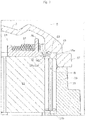
- the cover 5 on which the bent wire rod 51 rests is fastened to the housing 3. Consequently, as illustrated in Figures 6 and 7 , the bent wire rod 51 (the depressions 53b) contacts the peripheral edge 38a of the stator core 31.
- the bent wire rod 51 (the projections 53a) contacts the protrusion 45 along the side wall 41.
- the bent wire rod 51 is compressingly deformable along the axis R.
- the compressingly deformed bent wire rod 51 exerts an elastic force along the axis R.
- the protrusion 45 receives an elastic force upward along the axis R generated by the bent wire rod 51.
- the stator 13 receives an elastic force downward along the axis R generated by the bent wire rod 51.
- the collar 36 extends adjacent to the outer peripheral edge 39 of the stator core 31. Accordingly, the collar 36 allows suppressing a radial shifting of the contact position of the bent wire rod 51 to the stator 13 suitably. In other words, the collar 36 allows suppressing the shifting of the depressions 53b of the bent wire rod 51 suitably. In addition, the collar 36 is integrated with the insulated bobbin 35, achieving a simplification of the structure.
Landscapes
- Engineering & Computer Science (AREA)
- Power Engineering (AREA)
- Mechanical Engineering (AREA)
- Transportation (AREA)
- Manufacturing & Machinery (AREA)
- Chemical & Material Sciences (AREA)
- Combustion & Propulsion (AREA)
- Insulation, Fastening Of Motor, Generator Windings (AREA)
- Iron Core Of Rotating Electric Machines (AREA)
- Motor Or Generator Frames (AREA)
- Manufacture Of Motors, Generators (AREA)
Claims (13)
- Eine Statorstruktur, die folgende Merkmale aufweist:einen Stator (13);ein Gehäuse (3), das ein röhrenförmiges Segment (11) umfasst, wobei der Stator (13) in dem röhrenförmigen Segment (11) untergebracht ist;eine Abdeckung (5), die mit dem Gehäuse (3) gekoppelt ist, um eine obere Öffnung des röhrenförmigen Segments (11) zu blockieren; undeine gebogene Drahtstange (51), die aus einem Draht zum Drücken des Stators (13) gegen das röhrenförmige Segment (11) gebildet ist, wobei die gebogene Drahtstange (51) in einem zusammengedrückten Zustand in Kontakt mit einer oberen Fläche (38) des Stators (13) und einer hinteren Fläche der Abdeckung (5) ist, um entlang einer Achse (R) verformt zu sein, die im Wesentlichen der Mittelachse des röhrenförmigen Segments (11) entspricht,die gebogene Drahtstange (51) bei Betrachtung entlang der Achse (R) eine im Wesentlichen ringförmige Form mit einem geöffneten Abschnitt aufweist und Überstände (53a), die entlang der Achse (R) nach oben vorstehen, und Vertiefungen (53b), die entlang der Achse (R) nach unten vorstehen, umfasst, wobei die Überstände (53a) und Vertiefungen (53b) abwechselnd und nacheinander angeordnet sind, wobei die gebogene Drahtstange (51) derart angeordnet ist, dass die Überstände (53a) in Kontakt mit der hinteren Fläche der Abdeckung (5) sind und die Vertiefungen (53b) in Kontakt mit der oberen Fläche (38) des Stators (13) sind,wobei die Abdeckung (5) folgende Merkmale aufweist:eine Seitenwand (41), die auf der hinteren Fläche der Abdeckung (5) in einer Umfangsrichtung (Q) um die Achse (R) gebildet ist und in Kontakt mit der gebogenen Drahtstange (51) ist, um eine elastische Kraft, die durch die gebogene Drahtstange (51) erzeugt wird, radial und nach außen relativ zu der Achse (R) aufzunehmen, undeinen Vorsprung (45), der von der Seitenwand (41) radial und nach innen relativ zu der Achse (R) vorsteht, um die Überstände (53a) zu berühren und eine nach oben gerichtete elastische Kraft, die durch die gebogene Drahtstange (51) erzeugt wird, entlang der Achse (R) aufzunehmen,wobei der Vorsprung (45) nach unten entlang der Achse (R) radial und nach innen geneigt ist, undeine Ausnehmung (H), in der die Überstände (53a) gehalten werden, die zwischen dem Vorsprung (45) und der Seitenwand (41) vorgesehen sind.
- Die Statorstruktur gemäß Anspruch 1, wobei
die gebogene Drahtstange (51) eine Mehrzahl von Ecken und eine Mehrzahl von geraden Abschnitten (55) umfasst, um bei Betrachtung entlang der Achse (R) im Wesentlichen polygonal zu sein, wobei der gerade Abschnitt (55) die benachbarten Ecken miteinander verbindet. - Die Statorstruktur gemäß Anspruch 2, wobei
die Ecken an den Überstanden (53a) oder den Vertiefungen (53b) gebildet sind. - Die Statorstruktur gemäß Anspruch 1, wobei
die Überstände (53a) und die Vertiefungen (53b) so gebogen sind, dass die äußere Form der gebogenen Drahtstange (51) bei Betrachtung entlang der Achse (R) eine im Wesentliche polygonale Form mit den Überständen (53a) und den Vertiefungen (53b) als Scheitelpunkten ist, und
die gebogene Drahtstange (51) gerade Abschnitte (55) umfasst, die jeweils den benachbarten Überstand (53a) und die benachbarte Vertiefung (53b) verbinden. - Die Statorstruktur gemäß einem der Ansprüche 1 bis 4, wobei
die gebogene Drahtstange (51) so verformt ist, dass derselbe eine Durchmesserabmessung aufweist, die kleiner als der Außendurchmesser des Stators (13) ist. - Die Statorstruktur gemäß einem der Ansprüche 1 bis 5, wobei
die gebogene Drahtstange (51) aus einer Drahtstange mit einem kreisförmigen Querschnitt gebildet ist. - Die Statorstruktur gemäß einem der Ansprüche 1 bis 6, wobei
die Seitenwand (41) einen Innendurchmesser aufweist, der geringfügig größer als ein Außendurchmesser des Stators (13) ist. - Die Statorstruktur gemäß einem der Ansprüche 1 bis 7, wobei
der Stator (13) einen Statorkern (31) und eine Spule (37) umfasst, die um den Statorkern gewickelt ist (31), und
die gebogene Drahtstange (51) eine obere Fläche (38) des Statorkerns (31) direkt berührt. - Die Statorstruktur gemäß Anspruch 8, wobei
der Stator (13) ferner ein Begrenzungselement (36) umfasst, das auf der oberen Fläche (38) des Statorkerns (31) und innerhalb eines Außenumfangsrand des Statorkerns (31) angeordnet ist, um ein Verschieben der gebogenen Drahtstange (51) radial und nach innen zu begrenzen. - Die Statorstruktur gemäß Anspruch 9, wobei
der Stator (13) ferner einen isolierten Spulenkörper (35) umfasst, der zwischen dem Statorkern (31) und der Spule (37) angeordnet ist, um den Statorkern (31) zu bedecken, und
das Begrenzungselement (36) in den isolierten Spulenkörper (35) integriert ist. - Eine Antriebseinheit, die folgende Merkmale aufweist:einen Motor (18), der zum Erzeugen von Leistung konfiguriert ist, wobei der Motor (18) einen Rotor (16) und einen Stator (13) außerhalb des Rotors (16) umfasst; undeine Statorstruktur gemäß einem der Ansprüche 1 bis 10.
- Die Antriebseinheit gemäß Anspruch 11, wobei
die Antriebseinheit auf einem Zweirad (61) befestigt werden kann,
das Gehäuse (3) ferner ein Kurbelwellenkammer (72) umfasst, in das eine Kurbelwelle (71) des Zweirads (61) eingesetzt ist, und
der Motor (18) zum Erzeugen von Leistung konfiguriert ist, um einen Druck auf Pedale (73), die mit der Kurbelwelle (71) gekoppelt sind, zu unterstützen. - Ein Zweirad (61), das einen Karosserierahmen (63), ein Vorderrad (65) und ein Hinterrad (67), die auf dem Karosserierahmen (63) drehbar gelagert sind, und einen Haltegriff (69) aufweist, der auf dem Karosserierahmen (63) gelagert ist und dazu konfiguriert ist, das Vorderrad (65) zu steuern, wobei das Zweirad (61) ferner die Antriebseinheit gemäß Anspruch 11 oder 12 aufweist.
Priority Applications (1)
| Application Number | Priority Date | Filing Date | Title |
|---|---|---|---|
| EP19197988.9A EP3605795B1 (de) | 2011-03-09 | 2012-02-21 | Statorbefestigungsstruktur und antriebseinheit |
Applications Claiming Priority (2)
| Application Number | Priority Date | Filing Date | Title |
|---|---|---|---|
| JP2011051685A JP5603810B2 (ja) | 2011-03-09 | 2011-03-09 | ステータの固定構造および駆動装置 |
| PCT/JP2012/001154 WO2012120801A1 (ja) | 2011-03-09 | 2012-02-21 | ステータの固定構造および駆動装置 |
Related Child Applications (2)
| Application Number | Title | Priority Date | Filing Date |
|---|---|---|---|
| EP19197988.9A Division-Into EP3605795B1 (de) | 2011-03-09 | 2012-02-21 | Statorbefestigungsstruktur und antriebseinheit |
| EP19197988.9A Division EP3605795B1 (de) | 2011-03-09 | 2012-02-21 | Statorbefestigungsstruktur und antriebseinheit |
Publications (3)
| Publication Number | Publication Date |
|---|---|
| EP2685604A1 EP2685604A1 (de) | 2014-01-15 |
| EP2685604A4 EP2685604A4 (de) | 2016-03-09 |
| EP2685604B1 true EP2685604B1 (de) | 2019-11-27 |
Family
ID=46797777
Family Applications (2)
| Application Number | Title | Priority Date | Filing Date |
|---|---|---|---|
| EP19197988.9A Active EP3605795B1 (de) | 2011-03-09 | 2012-02-21 | Statorbefestigungsstruktur und antriebseinheit |
| EP12755553.0A Active EP2685604B1 (de) | 2011-03-09 | 2012-02-21 | Statorverankerungsstruktur und antriebsvorrichtung |
Family Applications Before (1)
| Application Number | Title | Priority Date | Filing Date |
|---|---|---|---|
| EP19197988.9A Active EP3605795B1 (de) | 2011-03-09 | 2012-02-21 | Statorbefestigungsstruktur und antriebseinheit |
Country Status (6)
| Country | Link |
|---|---|
| US (2) | US9236774B2 (de) |
| EP (2) | EP3605795B1 (de) |
| JP (1) | JP5603810B2 (de) |
| CN (2) | CN103415980B (de) |
| TW (2) | TWI443943B (de) |
| WO (1) | WO2012120801A1 (de) |
Families Citing this family (10)
| Publication number | Priority date | Publication date | Assignee | Title |
|---|---|---|---|---|
| JP5603810B2 (ja) * | 2011-03-09 | 2014-10-08 | ヤマハモーターエレクトロニクス株式会社 | ステータの固定構造および駆動装置 |
| JP6370736B2 (ja) | 2015-03-31 | 2018-08-08 | 株式会社シマノ | 自転車用ドライブユニット、および、このドライブユニットを備える自転車 |
| JP6514995B2 (ja) * | 2015-08-31 | 2019-05-15 | 株式会社シマノ | 自転車用ガードおよびこれを備えるドライブユニット |
| JP6721403B2 (ja) * | 2016-04-28 | 2020-07-15 | ヤマハ発動機株式会社 | 電動補助自転車 |
| USD936105S1 (en) * | 2018-06-15 | 2021-11-16 | Fukuta Electric & Machinery Co., Ltd. | Motor assembly for an electric scooter |
| USD936106S1 (en) * | 2019-03-12 | 2021-11-16 | Fukuta Electric & Machinery Co., Ltd. | Motor assembly for an electric scooter |
| DE102019215563A1 (de) * | 2019-10-10 | 2021-04-15 | Zf Friedrichshafen Ag | Stator einer elektrischen Maschine |
| FR3103653A1 (fr) * | 2019-11-22 | 2021-05-28 | Valeo Equipements Electriques Moteur | Machine électrique tournante avec blocage axial du stator |
| CN113036977B (zh) * | 2019-12-24 | 2025-09-05 | 广东德昌电机有限公司 | 泵及其电机定子 |
| JP1684126S (de) * | 2020-09-30 | 2021-04-26 |
Family Cites Families (18)
| Publication number | Priority date | Publication date | Assignee | Title |
|---|---|---|---|---|
| US2154146A (en) * | 1935-09-02 | 1939-04-11 | John Edward Becker | Electric motor, dynamo, and the like |
| JPS57186937A (en) | 1982-04-28 | 1982-11-17 | Toshiba Corp | Stator for electric rotary machine |
| JPH0326250U (de) * | 1989-07-21 | 1991-03-18 | ||
| JPH05137290A (ja) * | 1991-11-12 | 1993-06-01 | Mitsubishi Electric Corp | 車両用交流発電機 |
| US5315200A (en) * | 1992-07-16 | 1994-05-24 | Ford Motor Company | Electrical motor stator installation |
| JPH0670523A (ja) | 1992-08-19 | 1994-03-11 | Matsushita Electric Ind Co Ltd | ブラシレスモータ |
| KR100590436B1 (ko) | 1997-11-07 | 2006-06-19 | 코닌클리케 필립스 일렉트로닉스 엔.브이. | 화상 시퀀스 코딩 |
| US6100615A (en) * | 1998-05-11 | 2000-08-08 | Birkestrand; Orville J. | Modular motorized electric wheel hub assembly for bicycles and the like |
| JP3998118B2 (ja) * | 2000-10-10 | 2007-10-24 | 本田技研工業株式会社 | 電動車両 |
| US7026742B2 (en) * | 2002-04-01 | 2006-04-11 | Nissan Motor Co., Ltd. | Stator mounting for a double rotor electric motor |
| JP2004048925A (ja) * | 2002-07-12 | 2004-02-12 | Toyota Motor Corp | ステータの固定方法及び固定構造並びにロータの固定方法及び固定構造 |
| JP2005335536A (ja) * | 2004-05-27 | 2005-12-08 | Sanyo Electric Co Ltd | 電動車輪用ハブユニット及び該ハブユニットを具えた乗物 |
| CN101243594B (zh) * | 2005-10-24 | 2012-07-04 | 松下电器产业株式会社 | 电容电动机及其制造方法 |
| ES2398669T3 (es) * | 2006-06-02 | 2013-03-20 | Brose Fahrzeugteile Gmbh & Co. Kg, Wurzburg | Electromotor y procedimiento para la fabricación de un electromotor para un mecanismo de control de automóvil |
| JP2008271747A (ja) * | 2007-04-24 | 2008-11-06 | Asmo Co Ltd | 回転電機及びワッシャ部材 |
| JP4527145B2 (ja) * | 2007-11-12 | 2010-08-18 | 三菱電機株式会社 | 電動パワーステアリング装置用モータ |
| JP2010178469A (ja) * | 2009-01-28 | 2010-08-12 | Calsonic Kansei Corp | モータ |
| JP5603810B2 (ja) * | 2011-03-09 | 2014-10-08 | ヤマハモーターエレクトロニクス株式会社 | ステータの固定構造および駆動装置 |
-
2011
- 2011-03-09 JP JP2011051685A patent/JP5603810B2/ja active Active
-
2012
- 2012-02-21 US US14/003,291 patent/US9236774B2/en active Active
- 2012-02-21 EP EP19197988.9A patent/EP3605795B1/de active Active
- 2012-02-21 CN CN201280012263.3A patent/CN103415980B/zh active Active
- 2012-02-21 EP EP12755553.0A patent/EP2685604B1/de active Active
- 2012-02-21 CN CN201610096390.6A patent/CN105553138B/zh active Active
- 2012-02-21 WO PCT/JP2012/001154 patent/WO2012120801A1/ja not_active Ceased
- 2012-03-07 TW TW101107775A patent/TWI443943B/zh active
- 2012-03-07 TW TW103120391A patent/TWI488411B/zh active
-
2015
- 2015-12-04 US US14/959,044 patent/US9496763B2/en active Active
Non-Patent Citations (1)
| Title |
|---|
| None * |
Also Published As
| Publication number | Publication date |
|---|---|
| CN105553138B (zh) | 2018-09-28 |
| CN103415980B (zh) | 2016-03-30 |
| TW201438381A (zh) | 2014-10-01 |
| JP5603810B2 (ja) | 2014-10-08 |
| EP2685604A4 (de) | 2016-03-09 |
| EP3605795A1 (de) | 2020-02-05 |
| TW201251281A (en) | 2012-12-16 |
| TWI488411B (zh) | 2015-06-11 |
| WO2012120801A1 (ja) | 2012-09-13 |
| EP2685604A1 (de) | 2014-01-15 |
| US9236774B2 (en) | 2016-01-12 |
| US20130341112A1 (en) | 2013-12-26 |
| TWI443943B (zh) | 2014-07-01 |
| CN103415980A (zh) | 2013-11-27 |
| US9496763B2 (en) | 2016-11-15 |
| US20160087504A1 (en) | 2016-03-24 |
| CN105553138A (zh) | 2016-05-04 |
| EP3605795B1 (de) | 2020-11-11 |
| JP2012191714A (ja) | 2012-10-04 |
Similar Documents
| Publication | Publication Date | Title |
|---|---|---|
| EP3605795B1 (de) | Statorbefestigungsstruktur und antriebseinheit | |
| EP3175998B1 (de) | Sensorvorrichtung für eine fahrradnabe | |
| KR101756475B1 (ko) | 전기 자전거의 허브와 휠의 결합구조 | |
| US20140121049A1 (en) | Bicycle drive unit | |
| KR20010029719A (ko) | 로터 구조 | |
| JP2009033884A (ja) | ステータおよびステータの製造方法 | |
| CN105075076B (zh) | 内燃机用旋转电机 | |
| JP4015752B2 (ja) | ハイブリッド車両用モータ | |
| CN203554165U (zh) | 一种塑封电机的安装结构 | |
| US20130342074A1 (en) | Stator-fixed structure and driving unit | |
| US20120112599A1 (en) | Stator and Motor Comprising Same | |
| JP2004215441A (ja) | 回転電機ユニット | |
| JP5971315B2 (ja) | 内燃機関用回転電機 | |
| JP6740464B2 (ja) | アウターロータ型回転電機 | |
| CN105932811A (zh) | 电机结构组件 | |
| JP6773858B2 (ja) | 磁気発生装置 | |
| JP2021078283A (ja) | 回転電機 |
Legal Events
| Date | Code | Title | Description |
|---|---|---|---|
| PUAI | Public reference made under article 153(3) epc to a published international application that has entered the european phase |
Free format text: ORIGINAL CODE: 0009012 |
|
| 17P | Request for examination filed |
Effective date: 20131002 |
|
| AK | Designated contracting states |
Kind code of ref document: A1 Designated state(s): AL AT BE BG CH CY CZ DE DK EE ES FI FR GB GR HR HU IE IS IT LI LT LU LV MC MK MT NL NO PL PT RO RS SE SI SK SM TR |
|
| DAX | Request for extension of the european patent (deleted) | ||
| RA4 | Supplementary search report drawn up and despatched (corrected) |
Effective date: 20160209 |
|
| RIC1 | Information provided on ipc code assigned before grant |
Ipc: H02K 1/18 20060101AFI20160203BHEP Ipc: H02K 5/04 20060101ALI20160203BHEP |
|
| GRAP | Despatch of communication of intention to grant a patent |
Free format text: ORIGINAL CODE: EPIDOSNIGR1 |
|
| STAA | Information on the status of an ep patent application or granted ep patent |
Free format text: STATUS: GRANT OF PATENT IS INTENDED |
|
| INTG | Intention to grant announced |
Effective date: 20190613 |
|
| GRAS | Grant fee paid |
Free format text: ORIGINAL CODE: EPIDOSNIGR3 |
|
| GRAA | (expected) grant |
Free format text: ORIGINAL CODE: 0009210 |
|
| STAA | Information on the status of an ep patent application or granted ep patent |
Free format text: STATUS: THE PATENT HAS BEEN GRANTED |
|
| AK | Designated contracting states |
Kind code of ref document: B1 Designated state(s): AL AT BE BG CH CY CZ DE DK EE ES FI FR GB GR HR HU IE IS IT LI LT LU LV MC MK MT NL NO PL PT RO RS SE SI SK SM TR |
|
| REG | Reference to a national code |
Ref country code: GB Ref legal event code: FG4D |
|
| REG | Reference to a national code |
Ref country code: CH Ref legal event code: EP |
|
| REG | Reference to a national code |
Ref country code: DE Ref legal event code: R096 Ref document number: 602012066031 Country of ref document: DE |
|
| REG | Reference to a national code |
Ref country code: AT Ref legal event code: REF Ref document number: 1207831 Country of ref document: AT Kind code of ref document: T Effective date: 20191215 |
|
| REG | Reference to a national code |
Ref country code: IE Ref legal event code: FG4D |
|
| REG | Reference to a national code |
Ref country code: NL Ref legal event code: FP |
|
| REG | Reference to a national code |
Ref country code: LT Ref legal event code: MG4D |
|
| PG25 | Lapsed in a contracting state [announced via postgrant information from national office to epo] |
Ref country code: NO Free format text: LAPSE BECAUSE OF FAILURE TO SUBMIT A TRANSLATION OF THE DESCRIPTION OR TO PAY THE FEE WITHIN THE PRESCRIBED TIME-LIMIT Effective date: 20200227 Ref country code: LT Free format text: LAPSE BECAUSE OF FAILURE TO SUBMIT A TRANSLATION OF THE DESCRIPTION OR TO PAY THE FEE WITHIN THE PRESCRIBED TIME-LIMIT Effective date: 20191127 Ref country code: BG Free format text: LAPSE BECAUSE OF FAILURE TO SUBMIT A TRANSLATION OF THE DESCRIPTION OR TO PAY THE FEE WITHIN THE PRESCRIBED TIME-LIMIT Effective date: 20200227 Ref country code: SE Free format text: LAPSE BECAUSE OF FAILURE TO SUBMIT A TRANSLATION OF THE DESCRIPTION OR TO PAY THE FEE WITHIN THE PRESCRIBED TIME-LIMIT Effective date: 20191127 Ref country code: LV Free format text: LAPSE BECAUSE OF FAILURE TO SUBMIT A TRANSLATION OF THE DESCRIPTION OR TO PAY THE FEE WITHIN THE PRESCRIBED TIME-LIMIT Effective date: 20191127 Ref country code: ES Free format text: LAPSE BECAUSE OF FAILURE TO SUBMIT A TRANSLATION OF THE DESCRIPTION OR TO PAY THE FEE WITHIN THE PRESCRIBED TIME-LIMIT Effective date: 20191127 Ref country code: GR Free format text: LAPSE BECAUSE OF FAILURE TO SUBMIT A TRANSLATION OF THE DESCRIPTION OR TO PAY THE FEE WITHIN THE PRESCRIBED TIME-LIMIT Effective date: 20200228 Ref country code: FI Free format text: LAPSE BECAUSE OF FAILURE TO SUBMIT A TRANSLATION OF THE DESCRIPTION OR TO PAY THE FEE WITHIN THE PRESCRIBED TIME-LIMIT Effective date: 20191127 |
|
| PG25 | Lapsed in a contracting state [announced via postgrant information from national office to epo] |
Ref country code: RS Free format text: LAPSE BECAUSE OF FAILURE TO SUBMIT A TRANSLATION OF THE DESCRIPTION OR TO PAY THE FEE WITHIN THE PRESCRIBED TIME-LIMIT Effective date: 20191127 Ref country code: HR Free format text: LAPSE BECAUSE OF FAILURE TO SUBMIT A TRANSLATION OF THE DESCRIPTION OR TO PAY THE FEE WITHIN THE PRESCRIBED TIME-LIMIT Effective date: 20191127 Ref country code: IS Free format text: LAPSE BECAUSE OF FAILURE TO SUBMIT A TRANSLATION OF THE DESCRIPTION OR TO PAY THE FEE WITHIN THE PRESCRIBED TIME-LIMIT Effective date: 20200327 |
|
| PG25 | Lapsed in a contracting state [announced via postgrant information from national office to epo] |
Ref country code: AL Free format text: LAPSE BECAUSE OF FAILURE TO SUBMIT A TRANSLATION OF THE DESCRIPTION OR TO PAY THE FEE WITHIN THE PRESCRIBED TIME-LIMIT Effective date: 20191127 |
|
| PG25 | Lapsed in a contracting state [announced via postgrant information from national office to epo] |
Ref country code: DK Free format text: LAPSE BECAUSE OF FAILURE TO SUBMIT A TRANSLATION OF THE DESCRIPTION OR TO PAY THE FEE WITHIN THE PRESCRIBED TIME-LIMIT Effective date: 20191127 Ref country code: PT Free format text: LAPSE BECAUSE OF FAILURE TO SUBMIT A TRANSLATION OF THE DESCRIPTION OR TO PAY THE FEE WITHIN THE PRESCRIBED TIME-LIMIT Effective date: 20200419 Ref country code: EE Free format text: LAPSE BECAUSE OF FAILURE TO SUBMIT A TRANSLATION OF THE DESCRIPTION OR TO PAY THE FEE WITHIN THE PRESCRIBED TIME-LIMIT Effective date: 20191127 Ref country code: CZ Free format text: LAPSE BECAUSE OF FAILURE TO SUBMIT A TRANSLATION OF THE DESCRIPTION OR TO PAY THE FEE WITHIN THE PRESCRIBED TIME-LIMIT Effective date: 20191127 Ref country code: RO Free format text: LAPSE BECAUSE OF FAILURE TO SUBMIT A TRANSLATION OF THE DESCRIPTION OR TO PAY THE FEE WITHIN THE PRESCRIBED TIME-LIMIT Effective date: 20191127 |
|
| REG | Reference to a national code |
Ref country code: DE Ref legal event code: R097 Ref document number: 602012066031 Country of ref document: DE |
|
| PG25 | Lapsed in a contracting state [announced via postgrant information from national office to epo] |
Ref country code: SK Free format text: LAPSE BECAUSE OF FAILURE TO SUBMIT A TRANSLATION OF THE DESCRIPTION OR TO PAY THE FEE WITHIN THE PRESCRIBED TIME-LIMIT Effective date: 20191127 Ref country code: SM Free format text: LAPSE BECAUSE OF FAILURE TO SUBMIT A TRANSLATION OF THE DESCRIPTION OR TO PAY THE FEE WITHIN THE PRESCRIBED TIME-LIMIT Effective date: 20191127 |
|
| REG | Reference to a national code |
Ref country code: AT Ref legal event code: MK05 Ref document number: 1207831 Country of ref document: AT Kind code of ref document: T Effective date: 20191127 |
|
| REG | Reference to a national code |
Ref country code: CH Ref legal event code: PL |
|
| PLBE | No opposition filed within time limit |
Free format text: ORIGINAL CODE: 0009261 |
|
| STAA | Information on the status of an ep patent application or granted ep patent |
Free format text: STATUS: NO OPPOSITION FILED WITHIN TIME LIMIT |
|
| GBPC | Gb: european patent ceased through non-payment of renewal fee |
Effective date: 20200227 |
|
| REG | Reference to a national code |
Ref country code: BE Ref legal event code: MM Effective date: 20200229 |
|
| PG25 | Lapsed in a contracting state [announced via postgrant information from national office to epo] |
Ref country code: LU Free format text: LAPSE BECAUSE OF NON-PAYMENT OF DUE FEES Effective date: 20200221 Ref country code: MC Free format text: LAPSE BECAUSE OF FAILURE TO SUBMIT A TRANSLATION OF THE DESCRIPTION OR TO PAY THE FEE WITHIN THE PRESCRIBED TIME-LIMIT Effective date: 20191127 |
|
| 26N | No opposition filed |
Effective date: 20200828 |
|
| PG25 | Lapsed in a contracting state [announced via postgrant information from national office to epo] |
Ref country code: AT Free format text: LAPSE BECAUSE OF FAILURE TO SUBMIT A TRANSLATION OF THE DESCRIPTION OR TO PAY THE FEE WITHIN THE PRESCRIBED TIME-LIMIT Effective date: 20191127 Ref country code: PL Free format text: LAPSE BECAUSE OF FAILURE TO SUBMIT A TRANSLATION OF THE DESCRIPTION OR TO PAY THE FEE WITHIN THE PRESCRIBED TIME-LIMIT Effective date: 20191127 Ref country code: SI Free format text: LAPSE BECAUSE OF FAILURE TO SUBMIT A TRANSLATION OF THE DESCRIPTION OR TO PAY THE FEE WITHIN THE PRESCRIBED TIME-LIMIT Effective date: 20191127 Ref country code: LI Free format text: LAPSE BECAUSE OF NON-PAYMENT OF DUE FEES Effective date: 20200229 Ref country code: CH Free format text: LAPSE BECAUSE OF NON-PAYMENT OF DUE FEES Effective date: 20200229 |
|
| PG25 | Lapsed in a contracting state [announced via postgrant information from national office to epo] |
Ref country code: IT Free format text: LAPSE BECAUSE OF FAILURE TO SUBMIT A TRANSLATION OF THE DESCRIPTION OR TO PAY THE FEE WITHIN THE PRESCRIBED TIME-LIMIT Effective date: 20191127 Ref country code: GB Free format text: LAPSE BECAUSE OF NON-PAYMENT OF DUE FEES Effective date: 20200227 Ref country code: FR Free format text: LAPSE BECAUSE OF NON-PAYMENT OF DUE FEES Effective date: 20200229 Ref country code: IE Free format text: LAPSE BECAUSE OF NON-PAYMENT OF DUE FEES Effective date: 20200221 |
|
| PG25 | Lapsed in a contracting state [announced via postgrant information from national office to epo] |
Ref country code: BE Free format text: LAPSE BECAUSE OF NON-PAYMENT OF DUE FEES Effective date: 20200229 |
|
| PG25 | Lapsed in a contracting state [announced via postgrant information from national office to epo] |
Ref country code: TR Free format text: LAPSE BECAUSE OF FAILURE TO SUBMIT A TRANSLATION OF THE DESCRIPTION OR TO PAY THE FEE WITHIN THE PRESCRIBED TIME-LIMIT Effective date: 20191127 Ref country code: MT Free format text: LAPSE BECAUSE OF FAILURE TO SUBMIT A TRANSLATION OF THE DESCRIPTION OR TO PAY THE FEE WITHIN THE PRESCRIBED TIME-LIMIT Effective date: 20191127 Ref country code: CY Free format text: LAPSE BECAUSE OF FAILURE TO SUBMIT A TRANSLATION OF THE DESCRIPTION OR TO PAY THE FEE WITHIN THE PRESCRIBED TIME-LIMIT Effective date: 20191127 |
|
| PG25 | Lapsed in a contracting state [announced via postgrant information from national office to epo] |
Ref country code: MK Free format text: LAPSE BECAUSE OF FAILURE TO SUBMIT A TRANSLATION OF THE DESCRIPTION OR TO PAY THE FEE WITHIN THE PRESCRIBED TIME-LIMIT Effective date: 20191127 |
|
| P01 | Opt-out of the competence of the unified patent court (upc) registered |
Effective date: 20230527 |
|
| PGFP | Annual fee paid to national office [announced via postgrant information from national office to epo] |
Ref country code: NL Payment date: 20240219 Year of fee payment: 13 |
|
| REG | Reference to a national code |
Ref country code: NL Ref legal event code: MM Effective date: 20250301 |
|
| PG25 | Lapsed in a contracting state [announced via postgrant information from national office to epo] |
Ref country code: NL Free format text: LAPSE BECAUSE OF NON-PAYMENT OF DUE FEES Effective date: 20250301 |
|
| REG | Reference to a national code |
Ref country code: DE Ref legal event code: R081 Ref document number: 602012066031 Country of ref document: DE Owner name: YAMAHA HATSUDOKI KABUSHIKI KAISHA, IWATA, JP Free format text: FORMER OWNER: YAMAHA MOTOR ELECTRONICS CO., LTD., SHIZUOKA, JP |
|
| PGFP | Annual fee paid to national office [announced via postgrant information from national office to epo] |
Ref country code: DE Payment date: 20260218 Year of fee payment: 15 |