EP2683885B1 - Universal profile member - Google Patents
Universal profile member Download PDFInfo
- Publication number
- EP2683885B1 EP2683885B1 EP12712308.1A EP12712308A EP2683885B1 EP 2683885 B1 EP2683885 B1 EP 2683885B1 EP 12712308 A EP12712308 A EP 12712308A EP 2683885 B1 EP2683885 B1 EP 2683885B1
- Authority
- EP
- European Patent Office
- Prior art keywords
- wall
- lateral wall
- profiled section
- bar
- central
- Prior art date
- Legal status (The legal status is an assumption and is not a legal conclusion. Google has not performed a legal analysis and makes no representation as to the accuracy of the status listed.)
- Active
Links
- 238000004519 manufacturing process Methods 0.000 claims description 4
- 239000004793 Polystyrene Substances 0.000 description 2
- 241001080024 Telles Species 0.000 description 2
- 229910052751 metal Inorganic materials 0.000 description 2
- 239000002184 metal Substances 0.000 description 2
- 239000004570 mortar (masonry) Substances 0.000 description 2
- 229920002223 polystyrene Polymers 0.000 description 2
- 229920000915 polyvinyl chloride Polymers 0.000 description 2
- 239000004800 polyvinyl chloride Substances 0.000 description 2
- 239000000956 alloy Substances 0.000 description 1
- 229910045601 alloy Inorganic materials 0.000 description 1
- 229910052782 aluminium Inorganic materials 0.000 description 1
- XAGFODPZIPBFFR-UHFFFAOYSA-N aluminium Chemical compound [Al] XAGFODPZIPBFFR-UHFFFAOYSA-N 0.000 description 1
- 238000005253 cladding Methods 0.000 description 1
- 239000002131 composite material Substances 0.000 description 1
- 230000005489 elastic deformation Effects 0.000 description 1
- 238000001125 extrusion Methods 0.000 description 1
- 239000011152 fibreglass Substances 0.000 description 1
- 239000003365 glass fiber Substances 0.000 description 1
- 238000005192 partition Methods 0.000 description 1
- 229920002994 synthetic fiber Polymers 0.000 description 1
Images


Classifications
-
- E—FIXED CONSTRUCTIONS
- E04—BUILDING
- E04B—GENERAL BUILDING CONSTRUCTIONS; WALLS, e.g. PARTITIONS; ROOFS; FLOORS; CEILINGS; INSULATION OR OTHER PROTECTION OF BUILDINGS
- E04B2/00—Walls, e.g. partitions, for buildings; Wall construction with regard to insulation; Connections specially adapted to walls
- E04B2/74—Removable non-load-bearing partitions; Partitions with a free upper edge
- E04B2/76—Removable non-load-bearing partitions; Partitions with a free upper edge with framework or posts of metal
- E04B2/78—Removable non-load-bearing partitions; Partitions with a free upper edge with framework or posts of metal characterised by special cross-section of the frame members as far as important for securing wall panels to a framework with or without the help of cover-strips
- E04B2/7854—Removable non-load-bearing partitions; Partitions with a free upper edge with framework or posts of metal characterised by special cross-section of the frame members as far as important for securing wall panels to a framework with or without the help of cover-strips of open profile
- E04B2/789—Removable non-load-bearing partitions; Partitions with a free upper edge with framework or posts of metal characterised by special cross-section of the frame members as far as important for securing wall panels to a framework with or without the help of cover-strips of open profile of substantially U- or C- section
-
- E—FIXED CONSTRUCTIONS
- E04—BUILDING
- E04B—GENERAL BUILDING CONSTRUCTIONS; WALLS, e.g. PARTITIONS; ROOFS; FLOORS; CEILINGS; INSULATION OR OTHER PROTECTION OF BUILDINGS
- E04B2/00—Walls, e.g. partitions, for buildings; Wall construction with regard to insulation; Connections specially adapted to walls
- E04B2/74—Removable non-load-bearing partitions; Partitions with a free upper edge
- E04B2/7407—Removable non-load-bearing partitions; Partitions with a free upper edge assembled using frames with infill panels or coverings only; made-up of panels and a support structure incorporating posts
- E04B2/7453—Removable non-load-bearing partitions; Partitions with a free upper edge assembled using frames with infill panels or coverings only; made-up of panels and a support structure incorporating posts with panels and support posts, extending from floor to ceiling
- E04B2/7459—Removable non-load-bearing partitions; Partitions with a free upper edge assembled using frames with infill panels or coverings only; made-up of panels and a support structure incorporating posts with panels and support posts, extending from floor to ceiling with telescoping posts to compensate for floor or ceiling irregularities
-
- E—FIXED CONSTRUCTIONS
- E04—BUILDING
- E04B—GENERAL BUILDING CONSTRUCTIONS; WALLS, e.g. PARTITIONS; ROOFS; FLOORS; CEILINGS; INSULATION OR OTHER PROTECTION OF BUILDINGS
- E04B2/00—Walls, e.g. partitions, for buildings; Wall construction with regard to insulation; Connections specially adapted to walls
- E04B2/74—Removable non-load-bearing partitions; Partitions with a free upper edge
- E04B2/76—Removable non-load-bearing partitions; Partitions with a free upper edge with framework or posts of metal
- E04B2/766—T-connections
- E04B2/767—Connections between wall studs and upper or lower locating rails
-
- E—FIXED CONSTRUCTIONS
- E04—BUILDING
- E04C—STRUCTURAL ELEMENTS; BUILDING MATERIALS
- E04C3/00—Structural elongated elements designed for load-supporting
- E04C3/02—Joists; Girders, trusses, or trusslike structures, e.g. prefabricated; Lintels; Transoms; Braces
- E04C3/04—Joists; Girders, trusses, or trusslike structures, e.g. prefabricated; Lintels; Transoms; Braces of metal
- E04C3/06—Joists; Girders, trusses, or trusslike structures, e.g. prefabricated; Lintels; Transoms; Braces of metal with substantially solid, i.e. unapertured, web
-
- E—FIXED CONSTRUCTIONS
- E04—BUILDING
- E04C—STRUCTURAL ELEMENTS; BUILDING MATERIALS
- E04C3/00—Structural elongated elements designed for load-supporting
- E04C3/02—Joists; Girders, trusses, or trusslike structures, e.g. prefabricated; Lintels; Transoms; Braces
- E04C3/28—Joists; Girders, trusses, or trusslike structures, e.g. prefabricated; Lintels; Transoms; Braces of materials not covered by groups E04C3/04 - E04C3/20
-
- E—FIXED CONSTRUCTIONS
- E04—BUILDING
- E04B—GENERAL BUILDING CONSTRUCTIONS; WALLS, e.g. PARTITIONS; ROOFS; FLOORS; CEILINGS; INSULATION OR OTHER PROTECTION OF BUILDINGS
- E04B2/00—Walls, e.g. partitions, for buildings; Wall construction with regard to insulation; Connections specially adapted to walls
- E04B2/74—Removable non-load-bearing partitions; Partitions with a free upper edge
- E04B2/82—Removable non-load-bearing partitions; Partitions with a free upper edge characterised by the manner in which edges are connected to the building; Means therefor; Special details of easily-removable partitions as far as related to the connection with other parts of the building
- E04B2/828—Connections between partitions and structural walls
-
- E—FIXED CONSTRUCTIONS
- E04—BUILDING
- E04C—STRUCTURAL ELEMENTS; BUILDING MATERIALS
- E04C3/00—Structural elongated elements designed for load-supporting
- E04C3/02—Joists; Girders, trusses, or trusslike structures, e.g. prefabricated; Lintels; Transoms; Braces
- E04C3/04—Joists; Girders, trusses, or trusslike structures, e.g. prefabricated; Lintels; Transoms; Braces of metal
- E04C2003/0404—Joists; Girders, trusses, or trusslike structures, e.g. prefabricated; Lintels; Transoms; Braces of metal beams, girders, or joists characterised by cross-sectional aspects
- E04C2003/0408—Joists; Girders, trusses, or trusslike structures, e.g. prefabricated; Lintels; Transoms; Braces of metal beams, girders, or joists characterised by cross-sectional aspects characterised by assembly or the cross-section
- E04C2003/0413—Joists; Girders, trusses, or trusslike structures, e.g. prefabricated; Lintels; Transoms; Braces of metal beams, girders, or joists characterised by cross-sectional aspects characterised by assembly or the cross-section being built up from several parts
- E04C2003/0417—Joists; Girders, trusses, or trusslike structures, e.g. prefabricated; Lintels; Transoms; Braces of metal beams, girders, or joists characterised by cross-sectional aspects characterised by assembly or the cross-section being built up from several parts demountable
-
- E—FIXED CONSTRUCTIONS
- E04—BUILDING
- E04C—STRUCTURAL ELEMENTS; BUILDING MATERIALS
- E04C3/00—Structural elongated elements designed for load-supporting
- E04C3/02—Joists; Girders, trusses, or trusslike structures, e.g. prefabricated; Lintels; Transoms; Braces
- E04C3/04—Joists; Girders, trusses, or trusslike structures, e.g. prefabricated; Lintels; Transoms; Braces of metal
- E04C2003/0404—Joists; Girders, trusses, or trusslike structures, e.g. prefabricated; Lintels; Transoms; Braces of metal beams, girders, or joists characterised by cross-sectional aspects
- E04C2003/0426—Joists; Girders, trusses, or trusslike structures, e.g. prefabricated; Lintels; Transoms; Braces of metal beams, girders, or joists characterised by cross-sectional aspects characterised by material distribution in cross section
- E04C2003/0434—Joists; Girders, trusses, or trusslike structures, e.g. prefabricated; Lintels; Transoms; Braces of metal beams, girders, or joists characterised by cross-sectional aspects characterised by material distribution in cross section the open cross-section free of enclosed cavities
-
- E—FIXED CONSTRUCTIONS
- E04—BUILDING
- E04C—STRUCTURAL ELEMENTS; BUILDING MATERIALS
- E04C3/00—Structural elongated elements designed for load-supporting
- E04C3/02—Joists; Girders, trusses, or trusslike structures, e.g. prefabricated; Lintels; Transoms; Braces
- E04C3/04—Joists; Girders, trusses, or trusslike structures, e.g. prefabricated; Lintels; Transoms; Braces of metal
- E04C2003/0404—Joists; Girders, trusses, or trusslike structures, e.g. prefabricated; Lintels; Transoms; Braces of metal beams, girders, or joists characterised by cross-sectional aspects
- E04C2003/0443—Joists; Girders, trusses, or trusslike structures, e.g. prefabricated; Lintels; Transoms; Braces of metal beams, girders, or joists characterised by cross-sectional aspects characterised by substantial shape of the cross-section
- E04C2003/0465—Joists; Girders, trusses, or trusslike structures, e.g. prefabricated; Lintels; Transoms; Braces of metal beams, girders, or joists characterised by cross-sectional aspects characterised by substantial shape of the cross-section square- or rectangular-shaped
-
- E—FIXED CONSTRUCTIONS
- E04—BUILDING
- E04C—STRUCTURAL ELEMENTS; BUILDING MATERIALS
- E04C3/00—Structural elongated elements designed for load-supporting
- E04C3/02—Joists; Girders, trusses, or trusslike structures, e.g. prefabricated; Lintels; Transoms; Braces
- E04C3/04—Joists; Girders, trusses, or trusslike structures, e.g. prefabricated; Lintels; Transoms; Braces of metal
- E04C2003/0404—Joists; Girders, trusses, or trusslike structures, e.g. prefabricated; Lintels; Transoms; Braces of metal beams, girders, or joists characterised by cross-sectional aspects
- E04C2003/0443—Joists; Girders, trusses, or trusslike structures, e.g. prefabricated; Lintels; Transoms; Braces of metal beams, girders, or joists characterised by cross-sectional aspects characterised by substantial shape of the cross-section
- E04C2003/0473—U- or C-shaped
Definitions
- the present invention relates to a universal profile, more particularly a profile adapted to the production of walls.
- boxes or the like For the realization of caissons, boxes or the like, especially in so-called wet rooms (bathrooms, bathrooms, boiler rooms, toilets, ...), it is common to make boxes, boxes or the like to hide pipes , fittings or other technical elements.
- the walls of these boxes or the like are most often made using composite plates having an extruded polystyrene core, the latter being covered on its two main faces with a layer of glass fibers and a special mortar. .
- Such a plate is particularly well suited to serve as a support for a tile.
- the present invention therefore aims to provide a profile that facilitates the work of the artisan and can be used both as a rail (horizontal) as upright (vertical).
- a rail horizontal
- upright vertical
- the use of such a profile will not be limited to the production of boxes or the like in damp rooms but may advantageously also be used for other purposes.
- the present invention provides a profile for the realization of a structure of a wall, having a bottom of which extend on the same side two substantially parallel side walls.
- a profile corresponds to a section section U, known to those skilled in the art.
- a profile according to the present invention further comprises a third wall called central wall, parallel to the two side walls, disposed therebetween so as to be substantially closer to a side wall called first side wall than to the other side wall said second side wall.
- a profile is also known from DE 23 31 432 A1 , which discloses a profile for the realization of a wall structure with the features of the preamble of claim 1.
- the profile according to the present invention is a profile with the features of claim 1, of U-section, a branch is split in two. This split branch is then formed here by the central wall and the first side wall.
- Such a general shape makes it possible to envisage various variant embodiments of a profile can be used to make a structure of a box or the like.
- the distance separating the central wall of the first side wall is less than twice the maximum thickness of the second side wall. This distance corresponds to the width of the space available between the central wall and the first side wall. This distance, in a preferred embodiment, will preferably be just greater than the maximum thickness of the second side wall, and will for example be equal to this maximum thickness increased by a few tenths of a millimeter.
- the height of the central wall is less than the height of each of the side walls.
- these profiles are preferably each such that the distance separating the second side wall of the central wall is greater than the height of the highest side wall increased by the maximum thickness of the bottom.
- the second side wall and the central wall each bear on their side facing the first side wall at least one hook.
- the two profiles extending in two orthogonal directions, it can be provided that at least one side wall has a slot perpendicular to the bottom of the profile, said slot being disposed at a distance one end of the profile corresponding substantially to the distance between the central wall of the second side wall.
- the bottom of the profile has at one of its ends a first longitudinal slot extending between the central wall and the first side wall and a second longitudinal slot adjacent to the second side wall, the distance separating the two longitudinal slots being equal to the distance between the central wall of the second side wall.
- the bottom, the two side walls and the central wall of a profile according to the present invention are substantially planar so as to facilitate the attachment of a facing plate on one or other of the faces of this profile.
- the present invention also relates to an assembly formed by two sections, as defined in claim 5.
- the present invention also relates to a structure as defined in claim 6, comprising substantially vertical uprights and substantially horizontal rails between which are arranged the vertical uprights, said structure being intended to receive a facing so as to form a wall, characterized in that at least one element of said structure selected from the set of uprights and rails of this structure comprises or is a profile according to one of claims 1 to 4, or at least one amount of this structure comprises a assembly according to claim 5.
- the figure 1 shows a cross section of an embodiment of a profile.
- the proposed profile has a plane bottom 2 of a given thickness over the entire width (and length) of the profile. Note that two side walls extend from the same side of the bottom 2 from the longitudinal free edges thereof.
- a third wall extends parallel to the two side walls, therebetween.
- This central wall 4 is arranged to be substantially closer to a side wall which will be called later first side wall 6, the other side wall being called later second side wall 8.
- the distance separating the central wall 4 from the first lateral wall 6 is such that between these two walls it is possible to introduce a second lateral wall 8.
- the width of the space left between the central wall 4 and the first side wall 6 is for example greater than the thickness of the second side wall 8 of a few tenths of millimeters, or even a millimeter. It is thus possible to provide that the width of the free space between the central wall 4 and the first lateral wall 6, corresponding to the distance separating the central wall 4 from the first lateral wall 6, is less than twice the thickness of the second side wall 8.
- a profile according to the present invention can accommodate between its central wall 4 and the second side wall 8, a second similar section rotated 90 °. It is provided here that the total height H of the profile is less than the width of the free space between the central wall 4 and the second side wall 8. This width corresponds to the distance D2 between the central wall 4 of the second side wall 8 It can also be assumed here that the width D2 is greater than the height H by a few tenths of a millimeter or possibly a few millimeters.
- e1 is the thickness of the central wall 4
- e2 is the thickness of the second side wall 8
- e3 is the thickness of the first side wall 6.
- the thickness at the bottom 2 is not necessarily constant either.
- the central wall 4 has a thickness similar to that of the second side wall 8
- the thickness of the bottom 2 is not constant, it will preferably be provided that the bottom face 10 of the bottom 2, that is to say the face opposite the various walls, is substantially flat.
- the figure 4 illustrates a profile according to the present invention in side view.
- This profile has a length L.
- L To be easily manipulated, we choose for example L between 1.50 m and 2.50 m.
- the section of the profile is constant over the entire length L thereof, except at the slots 12. These are formed in all the walls (central wall 4, first side wall 6 and second side wall 8) at a distance predetermined D of each free end of the profile. Each slot 12 is preferably made over the entire height of the corresponding wall.
- slots 12 are preferably wide enough to accommodate a bottom 2 of a similar profile according to the present invention. It is then possible to assemble two profiles according to the invention by introducing the bottom 2 of one of the profiles in the slots 12 of the other profile. The two sections then extend in directions perpendicular to each other.
- the figure 5 illustrates another alternative embodiment also for assembling two profiles according to the present invention perpendicularly one to the other. It is intended here to make slots 14 longitudinal at least one free end of a profile.
- a longitudinal slot 14 is thus made for example in the bottom 2 between the central wall 4 and the first side wall 6.
- Another slot 14, similar to the first, is in turn made in the bottom 2 in the immediate vicinity of the second side wall 8.
- the length of these slots 14 substantially corresponds to the greatest height of the central wall 4 and the second side wall 8.
- the figure 6 illustrates by way of non-limiting example a structure that can be obtained using a profile according to the present invention.
- the figure 7 illustrates an assembly of three profiles according to the present invention.
- This is an alternative embodiment of profile according to the present invention.
- a thickness e3 of the first side wall 6 less than the thicknesses e1 and e2 of the central wall 4 and the second side wall 8 respectively.
- it was planned to accommodate a single profile between the central wall 4 and the second side wall 8 it is provided in the embodiment of the figure 7 to accommodate two profiles nested head to tail as shown on the figure 2 between the central wall 4 and the second side wall 8 of the profile.
- the height of the various walls, the distance D2 separating the central wall 4 from the second lateral wall 8 and the maximum thickness of the bottom 2 are adapted so as to be able to realize the assembly shown on the drawing. figure 7 . There is therefore here a distance D2 corresponding to the distance between the central wall 4 and the second side wall 8 at least equal to the maximum height of a profile increased by the maximum thickness of the bottom 2 of a similar section.
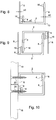
- FIGS. 8 to 10 illustrate an embodiment of a profile according to the invention.
- the overall structure of the profile remains the same, only change the various heights of walls and the thickness of these walls and the bottom.
- the same references are therefore used to designate similar elements.
- a bottom 2 with a lower face 12.
- On the opposite side to said lower face 12 extend a central wall 4, a first side wall 6 and a second side wall 8.
- the lower face 12 is flat.
- the thickness of the bottom 2 is less between the central wall 4 and the first lateral wall 6 than between the central wall 4 and the second lateral wall 8.
- the height of the central wall 4 is much lower than that of the side walls.
- the height of the second lateral wall 8 is slightly smaller than that of the first lateral wall 6.
- the height of a wall is called the distance separating its free edge from the lower face 12.
- the thicknesses of the three walls are different.
- the embodiment of a profile according to the invention shown on the Figures 8 to 10 also has the particularity to include hooks 16. These are made near the free edge of the central wall 4 and the second side wall 8, each time on the face of this wall facing the first side wall 6.
- the hooks 16 are formed by a fir profile on the corresponding face of the central wall 4 and the second lateral wall 8.
- the figure 9 shows a relative position of two similar sections according to the embodiments shown on the figure 8 , for the transport of these profiles.
- the figure 10 shows a position of implementation of two profiles similar to that shown on the figure 8 .
- two sections are mounted so that the second side wall 8 of a section comes to take place between the first side wall 6 of the other section and the central wall 4 of the other section.
- the hooks 16 of a central wall 4 of a profile then cooperate with the hooks 16 of the second side wall 8 of the other section.
- the distance between the central wall 4 and the first side wall 6 is such that the hooks 16 engage one with the other thanks to the elastic deformation of the corresponding profiles.
- the facing plates 18 are for example extruded polystyrene plates covered on both sides with a fiberglass layer and a mortar. It may be of course a face plate of another nature.
- a profile according to the present invention is preferably made of synthetic material, such as for example PVC (polyvinyl chloride).
- a profile according to the invention can then be obtained for example by extrusion or pultrusion.
- a profile according to the present invention allows a head-to-tail connection with a similar profile to form a section of substantially rectangular section.
- This new profile obtained by the interlocking of two profiles according to the present invention then has a greater inertia.
- This rectangular section profile can then be used to achieve a structure for the realization of a partition or a ceiling.
- two profiles according to the invention it is also possible with two profiles according to the invention to have an angle connection, the connection angle then being preferably between 45 and 135 °.
- the shape of the profile according to the present invention allows use in rail, amount, ....
Description
La présente invention concerne un profilé universel, plus particulièrement un profilé adapté à la réalisation de parois.The present invention relates to a universal profile, more particularly a profile adapted to the production of walls.
Pour la réalisation de caissons, boitiers ou similaires, notamment dans des locaux dits humides (salles d'eau, salles de bains, chaufferies, toilettes, ...), il est courant de réaliser des caissons, boitiers ou similaires pour dissimuler des conduites, raccords ou autres éléments techniques. Les parois de ces caissons ou similaires, sont réalisées le plus souvent à l'aide de plaques composites présentant une âme en polystyrène extrudé, cette dernière étant recouverte sur ses deux faces principales d'une couche de fibres de verre et d'un mortier spécial. Une telle plaque est particulièrement bien adaptée pour servir de support à un carrelage.For the realization of caissons, boxes or the like, especially in so-called wet rooms (bathrooms, bathrooms, boiler rooms, toilets, ...), it is common to make boxes, boxes or the like to hide pipes , fittings or other technical elements. The walls of these boxes or the like are most often made using composite plates having an extruded polystyrene core, the latter being covered on its two main faces with a layer of glass fibers and a special mortar. . Such a plate is particularly well suited to serve as a support for a tile.
Pour maintenir les plaques utilisées pour réaliser le caisson, il convient de réaliser une ossature. Celle-ci est le plus souvent fabriquée à l'aide de profilés métalliques en U qui sont découpés, pliés, ... à façon par l'artisan réalisant le caisson.To maintain the plates used to make the box, it is necessary to realize a frame. This is most often made using U-shaped metal profiles that are cut, folded, ... by the craftsman making the box.
La présente invention a alors pour but de fournir un profilé qui facilite le travail de l'artisan et qui puisse être utilisé aussi bien comme rail (horizontal) que comme montant (vertical). Bien entendu, l'utilisation d'un tel profilé ne sera pas limité à la réalisation de caissons ou similaires dans des locaux humides mais pourra avantageusement être également utilisé à d'autres fins.The present invention therefore aims to provide a profile that facilitates the work of the artisan and can be used both as a rail (horizontal) as upright (vertical). Of course, the use of such a profile will not be limited to the production of boxes or the like in damp rooms but may advantageously also be used for other purposes.
À cet effet, la présente invention propose un profilé destiné à la réalisation d'une structure d'une paroi, présentant un fond duquel s'étendent d'un même côté deux parois latérales sensiblement parallèles. Un tel profilé correspond à un profilé à section en U, connu de l'homme du métier.To this end, the present invention provides a profile for the realization of a structure of a wall, having a bottom of which extend on the same side two substantially parallel side walls. Such a profile corresponds to a section section U, known to those skilled in the art.
Un profilé selon la présente invention comporte en outre une troisième paroi appelée paroi centrale, parallèle aux deux parois latérales, disposée entre celles-ci de manière à être sensiblement plus proche d'une paroi latérale dite première paroi latérale que de l'autre paroi latérale dite seconde paroi latérale. Un tel profilé est également connu de
Ainsi, le profilé selon la présente invention est un profilé avec les caractéristiques de la revendication 1, de section en U dont une branche est dédoublée en deux. Cette branche dédoublée est alors formée ici par la paroi centrale et la première paroi latérale. Une telle forme générale permet d'envisager diverses variantes de réalisation d'un profilé pouvant être utilisé pour réaliser une structure d'un caisson ou similaire.Thus, the profile according to the present invention is a profile with the features of claim 1, of U-section, a branch is split in two. This split branch is then formed here by the central wall and the first side wall. Such a general shape makes it possible to envisage various variant embodiments of a profile can be used to make a structure of a box or the like.
Pour permettre un montage tête bêche de deux profilés similaires et obtenir ainsi un profilé fermé d'inertie améliorée, il est proposé, selon la revendication 1, pour un profilé selon la présente invention que la distance séparant la paroi centrale de la première paroi latérale soit inférieure au double de l'épaisseur maximale de la seconde paroi latérale. Cette distance correspond à la largeur de l'espace disponible entre la paroi centrale et la première paroi latérale. Cette distance, dans une forme de réalisation préférée, sera de préférence juste supérieure à l'épaisseur maximale de la seconde paroi latérale, et sera par exemple égale à cette épaisseur maximale augmentée de quelques dixièmes de millimètre.To allow a head-to-tail assembly of two similar sections and thus obtain an improved closed profile of inertia, it is proposed, according to claim 1, for a profile according to the present invention that the distance separating the central wall of the first side wall is less than twice the maximum thickness of the second side wall. This distance corresponds to the width of the space available between the central wall and the first side wall. This distance, in a preferred embodiment, will preferably be just greater than the maximum thickness of the second side wall, and will for example be equal to this maximum thickness increased by a few tenths of a millimeter.
Pour faciliter un emboîtement tête bêche de deux profilés selon l'invention, il est également prévu que la hauteur de la paroi centrale, mesurée à partir du fond, est inférieure à la hauteur de chacune des parois latérales.To facilitate a head-to-tail connection of two profiles according to the invention, it is also provided that the height of the central wall, measured from the bottom, is less than the height of each of the side walls.
Pour qu'il soit possible d'insérer un second profilé similaire à un premier profilé selon la présente invention entre la paroi centrale et la seconde paroi latérale du premier profilé, ces profilés sont de préférence chacun tel que la distance séparant la seconde paroi latérale de la paroi centrale est supérieure à la hauteur de la paroi latérale la plus haute augmentée de l'épaisseur maximale du fond.So that it is possible to insert a second section similar to a first section according to the present invention between the central wall and the second side wall of the first section, these profiles are preferably each such that the distance separating the second side wall of the central wall is greater than the height of the highest side wall increased by the maximum thickness of the bottom.
Pour permettre un accrochage de deux profilés similaires selon l'invention, la seconde paroi latérale et la paroi centrale portent chacune sur leur face orientée vers la première paroi latérale au moins un crochet.To allow a hooking of two similar sections according to the invention, the second side wall and the central wall each bear on their side facing the first side wall at least one hook.
Pour faciliter l'assemblage de deux profilés selon l'invention, les deux profilés s'étendant dans deux directions orthogonales, on peut prévoir qu'au moins une paroi latérale présente une fente perpendiculaire au fond du profilé, ladite fente étant disposée à une distance d'une extrémité du profilé correspondant sensiblement à la distance séparant la paroi centrale de la seconde paroi latérale.To facilitate the assembly of two profiles according to the invention, the two profiles extending in two orthogonal directions, it can be provided that at least one side wall has a slot perpendicular to the bottom of the profile, said slot being disposed at a distance one end of the profile corresponding substantially to the distance between the central wall of the second side wall.
Selon une autre variante de réalisation, toujours pour faciliter un assemblage orthogonal de deux profilés, le fond du profilé présente au niveau de l'une de ses extrémités une première fente longitudinale s'étendant entre la paroi centrale et la première paroi latérale et une seconde fente longitudinale adjacente à la seconde paroi latérale, la distance séparant les deux fentes longitudinales étant égale à la distance séparant la paroi centrale de la seconde paroi latérale.According to another variant embodiment, again to facilitate an orthogonal assembly of two profiles, the bottom of the profile has at one of its ends a first longitudinal slot extending between the central wall and the first side wall and a second longitudinal slot adjacent to the second side wall, the distance separating the two longitudinal slots being equal to the distance between the central wall of the second side wall.
Le fond, les deux parois latérales et la paroi centrale d'un profilé selon la présente invention sont sensiblement plans de manière à faciliter la fixation d'une plaque de parement sur l'une ou l'autre des faces de ce profilé.The bottom, the two side walls and the central wall of a profile according to the present invention are substantially planar so as to facilitate the attachment of a facing plate on one or other of the faces of this profile.
La présente invention concerne aussi un ensemble formé par deux profilés, tel que défini à la revendication 5.The present invention also relates to an assembly formed by two sections, as defined in claim 5.
Enfin, la présente invention concerne également une structure telle que définie dans la revendication 6, comportant des montants sensiblement verticaux et des rails sensiblement horizontaux entre lesquels sont disposés les montants verticaux, ladite structure étant destinée à recevoir un parement de manière à former une paroi, caractérisée en ce qu'au moins un élément de ladite structure choisi dans l'ensemble des montants et des rails de cette structure comporte ou est un profilé selon l'une des revendications 1 à 4, ou au moins un montant de cette structure comporte un ensemble selon la revendication 5.Finally, the present invention also relates to a structure as defined in
Des détails et avantages de la présente invention ressortiront mieux de la description qui suit, faite en référence aux dessins schématiques annexés sur lesquels :
- La
figure 1 est une vue en section d'un profilé ne présentant pas toutes les caractéristiques de la présente invention définies à la revendication 1, - Les
figures 2 et 3 illustrent, en section, des coopérations selon la présente invention telle que revendiquée de deux profilés tels celui montré sur lafigure 1 , - La
figure 4 est une vue de côté d'un profilé présentant les caractéristiques de larevendication 2, - La
figure 5 est une vue en perspective illustrant les caractéristiques de larevendication 4, - La
figure 6 illustre un montage pouvant être réalisé avec des profilés selon la présente invention, - La
figure 7 illustre un autre montage pouvant être réalisé avec des profilés selon la présente invention, - La
figure 8 montre une vue en section d'un profilé selon la présente invention telle que définie à la revendication 1, - La
figure 9 illustre une position de livraison pour des profilés tels celui montré sur lafigure 8 , et - La
figure 10 illustre la position en oeuvre de deux profilés présentant la section montrée sur lafigure 8 .
- The
figure 1 is a sectional view of a profile not having all the features of the present invention defined in claim 1, - The
Figures 2 and 3 illustrate, in section, cooperations according to the present invention as claimed of two profiles such as that shown on thefigure 1 , - The
figure 4 is a side view of a profile having the features ofclaim 2, - The
figure 5 is a perspective view illustrating the features ofclaim 4, - The
figure 6 illustrates an assembly that can be made with profiles according to the present invention, - The
figure 7 illustrates another arrangement that can be realized with profiles according to the present invention, - The
figure 8 shows a sectional view of a profile according to the present invention as defined in claim 1, - The
figure 9 illustrates a delivery position for profiles such as the one shown on thefigure 8 , and - The
figure 10 illustrates the position of two profiles having the section shown on thefigure 8 .
La
Comme on le voit sur cette même
Les dimensions de la section du profilé représenté sur la
Pour réaliser l'emboîtement montré sur la
Dans un tel cas de figure, on peut donc venir emboîter tête bêche deux profilés similaires selon la présente invention en introduisant à chaque fois la seconde paroi latérale 8 d'un profilé entre la paroi centrale 4 et la première paroi latérale 6 de l'autre profilé.In such a case, it is therefore possible to fit head-to-tail two similar sections according to the present invention by introducing each time the
Comme illustré sur la
Sur la
Dans une première forme de réalisation, on peut prévoir que les épaisseurs des trois parois sont les mêmes (e1 = e2 = e3). Dans une variante de réalisation, on peut toutefois prévoir également des épaisseurs de parois différentes. Ainsi, comme par exemple illustré sur la
L'épaisseur au niveau du fond 2 n'est pas forcément constante non plus. Dans le cas de figure représenté sur la
La
Dans la forme de réalisation représentée sur la
Ces fentes 12 sont de préférence suffisamment larges pour pouvoir recevoir un fond 2 d'un profilé similaire selon la présente invention. Il est alors possible d'assembler deux profilés selon l'invention en introduisant le fond 2 de l'un des profilés dans les fentes 12 de l'autre profilé. Les deux profilés s'étendent alors dans des directions perpendiculaires l'une par rapport à l'autre.These
La
La
La
Les
retrouve donc ici un fond 2 avec une face inférieure 12. Du côté opposé à ladite face inférieure 12 s'étendent une paroi centrale 4, une première paroi latérale 6 et une seconde paroi latérale 8.The
thus found here a bottom 2 with a
Dans la présente forme de réalisation, la face inférieure 12 est plane. L'épaisseur du fond 2 est moindre entre la paroi centrale 4 et la première paroi latérale 6 qu'entre la paroi centrale 4 et la seconde paroi latérale 8.In the present embodiment, the
Comme on peut le voir, la hauteur de la paroi centrale 4 est bien inférieure à celle des parois latérales. Comme il ressort d'une analyse de la
Dans la forme de réalisation représentée, les épaisseurs des trois parois sont différentes. On a ici e3 < e1 < e2.In the embodiment shown, the thicknesses of the three walls are different. Here we have e3 <e1 <e2.
La forme de réalisation d'un profilé selon l'invention montrée sur les
La
La
Dans cette position accrochée des deux profilés, on remarque que l'on forme une pièce sensiblement tubulaire de profilé extérieur rectangulaire. On peut ainsi réaliser un poteau sur lequel des plaques de parement 18 peuvent être fixées à l'aide de vis 20.In this hooked position of the two sections, it is noted that one forms a substantially tubular piece of rectangular outer profile. It is thus possible to make a post on which
Les plaques de parement 18 sont par exemple des plaques de polystyrène extrudé recouvertes des deux côtés d'une couche de fibre de verre et d'un mortier. Il peut s'agir bien entendu d'une plaque de parement d'une autre nature.The facing
Un profilé selon la présente invention est de préférence réalisé en matière synthétique, tel par exemple du PVC (polychlorure de vinyle). Un profilé selon l'invention peut alors être obtenu par exemple par extrusion ou pultrusion.A profile according to the present invention is preferably made of synthetic material, such as for example PVC (polyvinyl chloride). A profile according to the invention can then be obtained for example by extrusion or pultrusion.
Il est toutefois également envisageable de réaliser un profilé selon l'invention en métal. Il peut alors s'agir, à titre d'exemple, d'un profilé extrudé réalisé dans un alliage à base d'aluminium.However, it is also conceivable to produce a profile according to the invention made of metal. It can then be, for example, an extruded profile made of an aluminum-based alloy.
Comme il ressort de la description qui précède, un profilé selon la présente invention permet un emboîtement tête bêche avec un profilé similaire afin de constituer un profilé de section sensiblement rectangulaire. Ce nouveau profilé obtenu par l'emboîtement de deux profilés selon la présente invention, présente alors une inertie plus grande. Ce profilé à section rectangulaire peut être alors utilisé pour réaliser une structure pour la réalisation d'une cloison ou d'un plafond. Comme indiqué dans la description plus haut, il est possible de positionner perpendiculairement l'un à l'autre deux profilés selon la présente invention. Toutefois, on peut également envisager avec deux profilés selon l'invention d'avoir une liaison en angle, l'angle de liaison étant alors compris de préférence entre 45 et 135°.As apparent from the foregoing description, a profile according to the present invention allows a head-to-tail connection with a similar profile to form a section of substantially rectangular section. This new profile obtained by the interlocking of two profiles according to the present invention, then has a greater inertia. This rectangular section profile can then be used to achieve a structure for the realization of a partition or a ceiling. As indicated in the description above, it is possible to position two sections perpendicularly to one another according to the present invention. However, it is also possible with two profiles according to the invention to have an angle connection, the connection angle then being preferably between 45 and 135 °.
Enfin, en venant simplement couper un tronçon de profilé, il est possible de créer un connecteur servant soit à abouter deux profilés, soit à lier deux profilés en angle.Finally, simply by cutting a section of section, it is possible to create a connector for either to butt two profiles, or to bind two profiles at an angle.
La forme du profilé selon la présente invention, dans ses diverses variantes, permet une utilisation en rail, montant, ....The shape of the profile according to the present invention, in its various variants, allows use in rail, amount, ....
Bien entendu, la présente invention ne se limite pas aux formes de réalisation décrites ci-dessus à titre d'exemples non limitatifs et aux variantes évoquées. Elle concerne également toutes les variantes de réalisation à la portée de l'homme du métier dans le cadre des revendications ci-après.Of course, the present invention is not limited to the forms of embodiment described above as non-limiting examples and variants mentioned. It also relates to all the variants within the scope of those skilled in the art within the scope of the claims below.
Claims (6)
- A bar of profiled section adapted for the production of a structure of a wall, having a substantially planar base (2) and three substantially planar substantially parallel walls (4, 6, 8), extending on the same side of the base (2), two said walls being lateral walls (6, 8) and the third of said walls being a central wall (4) disposed between them so as to be substantially closer to one lateral wall designated first lateral wall (6), than the other lateral wall designated second lateral wall (8), the central wall (4) being of lower height relative to the two lateral walls (6, 8), said bar of profiled section being characterized in that:- the distance separating the central wall (4) from the first lateral wall (6) is less than twice the maximum thickness of the second lateral wall (8), and- the second lateral wall (8) and the central wall (4) each bear on their surface that is oriented towards the first lateral wall (6) at least one hook (16) to enable hooking together of two similar bars of profiled section.
- A bar of profiled section according to claim 1, characterized in that at least one lateral wall (6, 8) has a slot (12) perpendicular to the base (2) of the bar of profiled section, said slot (12) being disposed at a distance from an end of the bar of profiled section corresponding substantially to the distance separating the central wall (4) from the second lateral wall (8).
- A bar of profiled section according to claim 1 or 2, characterized in that the distance separating the second lateral wall (8) from the central wall (4) is greater than the height of the highest lateral wall increased by the maximum thickness of the base (2).
- A bar of profiled section according to one of claims 1 to 3, characterized in that the base (2) of the bar of profiled section has at one of its ends a first longitudinal slot (14) extending between the central wall (4) and the first lateral wall (6) and a second longitudinal slot (14) adjacent the second lateral wall (8), the distance separating the two longitudinal slots (14) being equal to the distance separating the central wall (4) from the second lateral wall (8).
- An assembly formed by two similar bars of profiled section adapted for the production of a structure of a wall, characterized in that each bar of profiled section is in accordance with one of claims 1 to 4 and in that the second lateral wall (8) of a bar of profiled section is disposed each time between the central wall (4) and the first lateral wall (6) of the other bar of profiled section, so as to produce a head-to-tail assembly of the two bars of profiled section.
- A structure comprising substantially vertical uprights and substantially horizontal rails between which are disposed the vertical uprights, said structure being adapted to receive a facing so as to form a wall, characterized in that at least one member of said structure chosen from all the uprights and rails of that structure comprises or is a bar of profiled section according to one of claims 1 to 4, or at least one upright of that structure comprises an assembly according to claim 5.
Applications Claiming Priority (2)
| Application Number | Priority Date | Filing Date | Title |
|---|---|---|---|
| FR1100673A FR2972426B1 (en) | 2011-03-07 | 2011-03-07 | UNIVERSAL PROFILE |
| PCT/FR2012/050432 WO2012120223A1 (en) | 2011-03-07 | 2012-03-01 | Universal profile member |
Publications (2)
| Publication Number | Publication Date |
|---|---|
| EP2683885A1 EP2683885A1 (en) | 2014-01-15 |
| EP2683885B1 true EP2683885B1 (en) | 2016-08-31 |
Family
ID=45930882
Family Applications (1)
| Application Number | Title | Priority Date | Filing Date |
|---|---|---|---|
| EP12712308.1A Active EP2683885B1 (en) | 2011-03-07 | 2012-03-01 | Universal profile member |
Country Status (3)
| Country | Link |
|---|---|
| EP (1) | EP2683885B1 (en) |
| FR (1) | FR2972426B1 (en) |
| WO (1) | WO2012120223A1 (en) |
Families Citing this family (3)
| Publication number | Priority date | Publication date | Assignee | Title |
|---|---|---|---|---|
| GB2536954A (en) * | 2015-04-02 | 2016-10-05 | Gbt Design Services Ltd | A wall frame assembly and wall assembly |
| US10597881B1 (en) | 2018-08-02 | 2020-03-24 | Rafael Huguet, Sr. | Wall system |
| FR3116841B1 (en) * | 2020-11-27 | 2023-03-03 | Ateliers Lr Etanco | System of deflectors for the insulation of roof spaces, in particular using a bulk material. |
Citations (1)
| Publication number | Priority date | Publication date | Assignee | Title |
|---|---|---|---|---|
| AU2004203463A1 (en) * | 2003-08-04 | 2005-02-24 | Fletcher Building Holdings Limited | A Stud |
Family Cites Families (3)
| Publication number | Priority date | Publication date | Assignee | Title |
|---|---|---|---|---|
| CH387915A (en) * | 1960-03-04 | 1965-02-15 | Menziken Aluminium Ag | Wall cladding |
| DE2331432A1 (en) * | 1973-06-20 | 1975-01-09 | Karl Eisen | Jointing strip for wall panels - is U-shaped with additional limbs forming channel for services |
| FR2633321B1 (en) * | 1988-06-23 | 1993-06-18 | Placoplatre Sa | PROCESS FOR THE ESTABLISHMENT, BETWEEN FLOOR AND CEILING, OF A PARTITION PANEL, AND SOLE SUITABLE FOR CARRYING OUT SUCH A PROCESS |
-
2011
- 2011-03-07 FR FR1100673A patent/FR2972426B1/en active Active
-
2012
- 2012-03-01 WO PCT/FR2012/050432 patent/WO2012120223A1/en active Application Filing
- 2012-03-01 EP EP12712308.1A patent/EP2683885B1/en active Active
Patent Citations (1)
| Publication number | Priority date | Publication date | Assignee | Title |
|---|---|---|---|---|
| AU2004203463A1 (en) * | 2003-08-04 | 2005-02-24 | Fletcher Building Holdings Limited | A Stud |
Also Published As
| Publication number | Publication date |
|---|---|
| WO2012120223A1 (en) | 2012-09-13 |
| FR2972426A1 (en) | 2012-09-14 |
| FR2972426B1 (en) | 2014-02-28 |
| EP2683885A1 (en) | 2014-01-15 |
Similar Documents
| Publication | Publication Date | Title |
|---|---|---|
| EP1964225B1 (en) | Wire-type cable raceway, especially a cable raceway for home use | |
| EP2022150B1 (en) | Separation and/or reinforcement device for a wire cable duct | |
| EP2166169A1 (en) | Structure made of at least two assembled building elements | |
| EP2683885B1 (en) | Universal profile member | |
| EP1936067A1 (en) | Wall covering and stabilisation element for such wall covering | |
| EP2884608B1 (en) | One piece splice plate for wire-based cable trays. | |
| WO2012066197A1 (en) | Device for attaching an element onto a mounting | |
| CA2973677A1 (en) | Device for attaching a solar panel | |
| EP2360381B1 (en) | Connection element for threshold strips | |
| FR2930315A1 (en) | C-shaped metallic section elements/furring strips connecting device for e.g. fixing faces to cover acoustic/thermal insulation blankets, has spaces possessing heights equal to thicknesses of edges so that edges are slid in respective spaces | |
| FR2766905A1 (en) | Folded section girder for building construction | |
| EP2596186B1 (en) | Structure for attaching wall cladding and associated wall assembly | |
| WO2014049293A1 (en) | Slide rail and motor vehicle seat comprising such a slide rail | |
| FR2891288A1 (en) | Telescopic stud for e.g. separator wall in office block, has sections embedded one in other with opposed cores so as to slide longitudinally with respect to each other for allowing overall height adjustment of stud based on ceiling height | |
| FR2989396A1 (en) | Extensible suspending rod for hanging U-shaped section with false ceiling wall, has longitudinal portions, and set of hollows provided in longitudinal portions, where set of hollows longitudinally emerge to free end of flat body | |
| EP2961897B1 (en) | Acute framework profile for forming a panel of a false ceiling or wall | |
| EP1670999B1 (en) | Panel useable in the form of a building element and a wall comprising said panel | |
| EP2123841B1 (en) | Profiled metal sheet | |
| FR2766904A1 (en) | C- sectional steel girder for building | |
| EP2264255B1 (en) | Wall structure, in particular of a hollow wall | |
| FR2941725A1 (en) | Parallelepiped block shaped thermal insulation element for construction block of e.g. longitudinal wall of concrete floor in building, has openings formed from lower and outer faces to open into housing to define assembling wall with block | |
| EP3816458B1 (en) | Clip for holding two flat elements | |
| FR2966482A1 (en) | Telescopic device for installing panels i.e. plasterboards for building, has sleeve mounted to slide along post to form telescopic assembly, which comprises stops for limiting stroke of sliding of sleeve along post | |
| FR3057886A1 (en) | FIXING SYSTEM, FACING ASSEMBLY OF AT LEAST TWO SUPERPOSED FIXING SYSTEMS, AND FENCE, PAREMENT AND FENCE COMPRISING AT LEAST ONE FACING ASSEMBLY | |
| FR2900945A1 (en) | FRAMEWORK FOR CEILING AND ROOFING, CORRESPONDING ROOFING AND CEILING, IN PARTICULAR FOR INCREASING FIRE RESISTANCE |
Legal Events
| Date | Code | Title | Description |
|---|---|---|---|
| PUAI | Public reference made under article 153(3) epc to a published international application that has entered the european phase |
Free format text: ORIGINAL CODE: 0009012 |
|
| 17P | Request for examination filed |
Effective date: 20130909 |
|
| AK | Designated contracting states |
Kind code of ref document: A1 Designated state(s): AL AT BE BG CH CY CZ DE DK EE ES FI FR GB GR HR HU IE IS IT LI LT LU LV MC MK MT NL NO PL PT RO RS SE SI SK SM TR |
|
| DAX | Request for extension of the european patent (deleted) | ||
| 17Q | First examination report despatched |
Effective date: 20150205 |
|
| REG | Reference to a national code |
Ref country code: DE Ref legal event code: R079 Ref document number: 602012022377 Country of ref document: DE Free format text: PREVIOUS MAIN CLASS: E04B0002780000 Ipc: E04B0002740000 |
|
| GRAP | Despatch of communication of intention to grant a patent |
Free format text: ORIGINAL CODE: EPIDOSNIGR1 |
|
| RIC1 | Information provided on ipc code assigned before grant |
Ipc: E04C 3/04 20060101ALI20160304BHEP Ipc: E04B 2/76 20060101ALI20160304BHEP Ipc: E04C 3/06 20060101ALI20160304BHEP Ipc: E04B 2/74 20060101AFI20160304BHEP Ipc: E04C 3/28 20060101ALI20160304BHEP Ipc: E04B 2/78 20060101ALI20160304BHEP |
|
| INTG | Intention to grant announced |
Effective date: 20160324 |
|
| GRAS | Grant fee paid |
Free format text: ORIGINAL CODE: EPIDOSNIGR3 |
|
| GRAA | (expected) grant |
Free format text: ORIGINAL CODE: 0009210 |
|
| AK | Designated contracting states |
Kind code of ref document: B1 Designated state(s): AL AT BE BG CH CY CZ DE DK EE ES FI FR GB GR HR HU IE IS IT LI LT LU LV MC MK MT NL NO PL PT RO RS SE SI SK SM TR |
|
| REG | Reference to a national code |
Ref country code: CH Ref legal event code: EP Ref country code: GB Ref legal event code: FG4D Free format text: NOT ENGLISH |
|
| REG | Reference to a national code |
Ref country code: IE Ref legal event code: FG4D Free format text: LANGUAGE OF EP DOCUMENT: FRENCH |
|
| REG | Reference to a national code |
Ref country code: DE Ref legal event code: R096 Ref document number: 602012022377 Country of ref document: DE |
|
| REG | Reference to a national code |
Ref country code: AT Ref legal event code: REF Ref document number: 825113 Country of ref document: AT Kind code of ref document: T Effective date: 20161015 |
|
| REG | Reference to a national code |
Ref country code: LT Ref legal event code: MG4D |
|
| REG | Reference to a national code |
Ref country code: NL Ref legal event code: MP Effective date: 20160831 |
|
| REG | Reference to a national code |
Ref country code: AT Ref legal event code: MK05 Ref document number: 825113 Country of ref document: AT Kind code of ref document: T Effective date: 20160831 |
|
| PG25 | Lapsed in a contracting state [announced via postgrant information from national office to epo] |
Ref country code: LT Free format text: LAPSE BECAUSE OF FAILURE TO SUBMIT A TRANSLATION OF THE DESCRIPTION OR TO PAY THE FEE WITHIN THE PRESCRIBED TIME-LIMIT Effective date: 20160831 Ref country code: FI Free format text: LAPSE BECAUSE OF FAILURE TO SUBMIT A TRANSLATION OF THE DESCRIPTION OR TO PAY THE FEE WITHIN THE PRESCRIBED TIME-LIMIT Effective date: 20160831 Ref country code: NO Free format text: LAPSE BECAUSE OF FAILURE TO SUBMIT A TRANSLATION OF THE DESCRIPTION OR TO PAY THE FEE WITHIN THE PRESCRIBED TIME-LIMIT Effective date: 20161130 Ref country code: HR Free format text: LAPSE BECAUSE OF FAILURE TO SUBMIT A TRANSLATION OF THE DESCRIPTION OR TO PAY THE FEE WITHIN THE PRESCRIBED TIME-LIMIT Effective date: 20160831 Ref country code: RS Free format text: LAPSE BECAUSE OF FAILURE TO SUBMIT A TRANSLATION OF THE DESCRIPTION OR TO PAY THE FEE WITHIN THE PRESCRIBED TIME-LIMIT Effective date: 20160831 |
|
| PG25 | Lapsed in a contracting state [announced via postgrant information from national office to epo] |
Ref country code: NL Free format text: LAPSE BECAUSE OF FAILURE TO SUBMIT A TRANSLATION OF THE DESCRIPTION OR TO PAY THE FEE WITHIN THE PRESCRIBED TIME-LIMIT Effective date: 20160831 Ref country code: GR Free format text: LAPSE BECAUSE OF FAILURE TO SUBMIT A TRANSLATION OF THE DESCRIPTION OR TO PAY THE FEE WITHIN THE PRESCRIBED TIME-LIMIT Effective date: 20161201 Ref country code: LV Free format text: LAPSE BECAUSE OF FAILURE TO SUBMIT A TRANSLATION OF THE DESCRIPTION OR TO PAY THE FEE WITHIN THE PRESCRIBED TIME-LIMIT Effective date: 20160831 Ref country code: AT Free format text: LAPSE BECAUSE OF FAILURE TO SUBMIT A TRANSLATION OF THE DESCRIPTION OR TO PAY THE FEE WITHIN THE PRESCRIBED TIME-LIMIT Effective date: 20160831 Ref country code: SE Free format text: LAPSE BECAUSE OF FAILURE TO SUBMIT A TRANSLATION OF THE DESCRIPTION OR TO PAY THE FEE WITHIN THE PRESCRIBED TIME-LIMIT Effective date: 20160831 Ref country code: ES Free format text: LAPSE BECAUSE OF FAILURE TO SUBMIT A TRANSLATION OF THE DESCRIPTION OR TO PAY THE FEE WITHIN THE PRESCRIBED TIME-LIMIT Effective date: 20160831 |
|
| REG | Reference to a national code |
Ref country code: FR Ref legal event code: PLFP Year of fee payment: 6 |
|
| PG25 | Lapsed in a contracting state [announced via postgrant information from national office to epo] |
Ref country code: RO Free format text: LAPSE BECAUSE OF FAILURE TO SUBMIT A TRANSLATION OF THE DESCRIPTION OR TO PAY THE FEE WITHIN THE PRESCRIBED TIME-LIMIT Effective date: 20160831 Ref country code: EE Free format text: LAPSE BECAUSE OF FAILURE TO SUBMIT A TRANSLATION OF THE DESCRIPTION OR TO PAY THE FEE WITHIN THE PRESCRIBED TIME-LIMIT Effective date: 20160831 |
|
| PG25 | Lapsed in a contracting state [announced via postgrant information from national office to epo] |
Ref country code: SM Free format text: LAPSE BECAUSE OF FAILURE TO SUBMIT A TRANSLATION OF THE DESCRIPTION OR TO PAY THE FEE WITHIN THE PRESCRIBED TIME-LIMIT Effective date: 20160831 Ref country code: BG Free format text: LAPSE BECAUSE OF FAILURE TO SUBMIT A TRANSLATION OF THE DESCRIPTION OR TO PAY THE FEE WITHIN THE PRESCRIBED TIME-LIMIT Effective date: 20161130 Ref country code: CZ Free format text: LAPSE BECAUSE OF FAILURE TO SUBMIT A TRANSLATION OF THE DESCRIPTION OR TO PAY THE FEE WITHIN THE PRESCRIBED TIME-LIMIT Effective date: 20160831 Ref country code: SK Free format text: LAPSE BECAUSE OF FAILURE TO SUBMIT A TRANSLATION OF THE DESCRIPTION OR TO PAY THE FEE WITHIN THE PRESCRIBED TIME-LIMIT Effective date: 20160831 Ref country code: PT Free format text: LAPSE BECAUSE OF FAILURE TO SUBMIT A TRANSLATION OF THE DESCRIPTION OR TO PAY THE FEE WITHIN THE PRESCRIBED TIME-LIMIT Effective date: 20170102 Ref country code: DK Free format text: LAPSE BECAUSE OF FAILURE TO SUBMIT A TRANSLATION OF THE DESCRIPTION OR TO PAY THE FEE WITHIN THE PRESCRIBED TIME-LIMIT Effective date: 20160831 Ref country code: PL Free format text: LAPSE BECAUSE OF FAILURE TO SUBMIT A TRANSLATION OF THE DESCRIPTION OR TO PAY THE FEE WITHIN THE PRESCRIBED TIME-LIMIT Effective date: 20160831 |
|
| REG | Reference to a national code |
Ref country code: DE Ref legal event code: R097 Ref document number: 602012022377 Country of ref document: DE |
|
| PG25 | Lapsed in a contracting state [announced via postgrant information from national office to epo] |
Ref country code: IT Free format text: LAPSE BECAUSE OF FAILURE TO SUBMIT A TRANSLATION OF THE DESCRIPTION OR TO PAY THE FEE WITHIN THE PRESCRIBED TIME-LIMIT Effective date: 20160831 |
|
| PLBE | No opposition filed within time limit |
Free format text: ORIGINAL CODE: 0009261 |
|
| STAA | Information on the status of an ep patent application or granted ep patent |
Free format text: STATUS: NO OPPOSITION FILED WITHIN TIME LIMIT |
|
| 26N | No opposition filed |
Effective date: 20170601 |
|
| PG25 | Lapsed in a contracting state [announced via postgrant information from national office to epo] |
Ref country code: SI Free format text: LAPSE BECAUSE OF FAILURE TO SUBMIT A TRANSLATION OF THE DESCRIPTION OR TO PAY THE FEE WITHIN THE PRESCRIBED TIME-LIMIT Effective date: 20160831 |
|
| REG | Reference to a national code |
Ref country code: DE Ref legal event code: R119 Ref document number: 602012022377 Country of ref document: DE |
|
| REG | Reference to a national code |
Ref country code: CH Ref legal event code: PL |
|
| GBPC | Gb: european patent ceased through non-payment of renewal fee |
Effective date: 20170301 |
|
| PG25 | Lapsed in a contracting state [announced via postgrant information from national office to epo] |
Ref country code: MC Free format text: LAPSE BECAUSE OF FAILURE TO SUBMIT A TRANSLATION OF THE DESCRIPTION OR TO PAY THE FEE WITHIN THE PRESCRIBED TIME-LIMIT Effective date: 20160831 |
|
| REG | Reference to a national code |
Ref country code: IE Ref legal event code: MM4A |
|
| PG25 | Lapsed in a contracting state [announced via postgrant information from national office to epo] |
Ref country code: LU Free format text: LAPSE BECAUSE OF NON-PAYMENT OF DUE FEES Effective date: 20170301 Ref country code: DE Free format text: LAPSE BECAUSE OF NON-PAYMENT OF DUE FEES Effective date: 20171003 |
|
| PG25 | Lapsed in a contracting state [announced via postgrant information from national office to epo] |
Ref country code: CH Free format text: LAPSE BECAUSE OF NON-PAYMENT OF DUE FEES Effective date: 20170331 Ref country code: GB Free format text: LAPSE BECAUSE OF NON-PAYMENT OF DUE FEES Effective date: 20170301 Ref country code: IE Free format text: LAPSE BECAUSE OF NON-PAYMENT OF DUE FEES Effective date: 20170301 Ref country code: LI Free format text: LAPSE BECAUSE OF NON-PAYMENT OF DUE FEES Effective date: 20170331 |
|
| REG | Reference to a national code |
Ref country code: BE Ref legal event code: MM Effective date: 20170331 |
|
| REG | Reference to a national code |
Ref country code: FR Ref legal event code: PLFP Year of fee payment: 7 |
|
| PG25 | Lapsed in a contracting state [announced via postgrant information from national office to epo] |
Ref country code: BE Free format text: LAPSE BECAUSE OF NON-PAYMENT OF DUE FEES Effective date: 20170331 |
|
| PG25 | Lapsed in a contracting state [announced via postgrant information from national office to epo] |
Ref country code: MT Free format text: LAPSE BECAUSE OF FAILURE TO SUBMIT A TRANSLATION OF THE DESCRIPTION OR TO PAY THE FEE WITHIN THE PRESCRIBED TIME-LIMIT Effective date: 20160831 |
|
| PG25 | Lapsed in a contracting state [announced via postgrant information from national office to epo] |
Ref country code: AL Free format text: LAPSE BECAUSE OF FAILURE TO SUBMIT A TRANSLATION OF THE DESCRIPTION OR TO PAY THE FEE WITHIN THE PRESCRIBED TIME-LIMIT Effective date: 20160831 |
|
| PG25 | Lapsed in a contracting state [announced via postgrant information from national office to epo] |
Ref country code: HU Free format text: LAPSE BECAUSE OF FAILURE TO SUBMIT A TRANSLATION OF THE DESCRIPTION OR TO PAY THE FEE WITHIN THE PRESCRIBED TIME-LIMIT; INVALID AB INITIO Effective date: 20120301 |
|
| PG25 | Lapsed in a contracting state [announced via postgrant information from national office to epo] |
Ref country code: CY Free format text: LAPSE BECAUSE OF NON-PAYMENT OF DUE FEES Effective date: 20160831 |
|
| PG25 | Lapsed in a contracting state [announced via postgrant information from national office to epo] |
Ref country code: MK Free format text: LAPSE BECAUSE OF FAILURE TO SUBMIT A TRANSLATION OF THE DESCRIPTION OR TO PAY THE FEE WITHIN THE PRESCRIBED TIME-LIMIT Effective date: 20160831 |
|
| PG25 | Lapsed in a contracting state [announced via postgrant information from national office to epo] |
Ref country code: TR Free format text: LAPSE BECAUSE OF FAILURE TO SUBMIT A TRANSLATION OF THE DESCRIPTION OR TO PAY THE FEE WITHIN THE PRESCRIBED TIME-LIMIT Effective date: 20160831 |
|
| PG25 | Lapsed in a contracting state [announced via postgrant information from national office to epo] |
Ref country code: IS Free format text: LAPSE BECAUSE OF FAILURE TO SUBMIT A TRANSLATION OF THE DESCRIPTION OR TO PAY THE FEE WITHIN THE PRESCRIBED TIME-LIMIT Effective date: 20161231 |
|
| PGFP | Annual fee paid to national office [announced via postgrant information from national office to epo] |
Ref country code: FR Payment date: 20230208 Year of fee payment: 12 |