EP2961897B1 - Acute framework profile for forming a panel of a false ceiling or wall - Google Patents
Acute framework profile for forming a panel of a false ceiling or wall Download PDFInfo
- Publication number
- EP2961897B1 EP2961897B1 EP14713185.8A EP14713185A EP2961897B1 EP 2961897 B1 EP2961897 B1 EP 2961897B1 EP 14713185 A EP14713185 A EP 14713185A EP 2961897 B1 EP2961897 B1 EP 2961897B1
- Authority
- EP
- European Patent Office
- Prior art keywords
- wall
- base
- profile
- angle
- face
- Prior art date
- Legal status (The legal status is an assumption and is not a legal conclusion. Google has not performed a legal analysis and makes no representation as to the accuracy of the status listed.)
- Not-in-force
Links
Images


Classifications
-
- E—FIXED CONSTRUCTIONS
- E04—BUILDING
- E04B—GENERAL BUILDING CONSTRUCTIONS; WALLS, e.g. PARTITIONS; ROOFS; FLOORS; CEILINGS; INSULATION OR OTHER PROTECTION OF BUILDINGS
- E04B9/00—Ceilings; Construction of ceilings, e.g. false ceilings; Ceiling construction with regard to insulation
- E04B9/04—Ceilings; Construction of ceilings, e.g. false ceilings; Ceiling construction with regard to insulation comprising slabs, panels, sheets or the like
- E04B9/0428—Ceilings; Construction of ceilings, e.g. false ceilings; Ceiling construction with regard to insulation comprising slabs, panels, sheets or the like having a closed frame around the periphery
-
- E—FIXED CONSTRUCTIONS
- E04—BUILDING
- E04B—GENERAL BUILDING CONSTRUCTIONS; WALLS, e.g. PARTITIONS; ROOFS; FLOORS; CEILINGS; INSULATION OR OTHER PROTECTION OF BUILDINGS
- E04B9/00—Ceilings; Construction of ceilings, e.g. false ceilings; Ceiling construction with regard to insulation
- E04B9/22—Connection of slabs, panels, sheets or the like to the supporting construction
- E04B9/24—Connection of slabs, panels, sheets or the like to the supporting construction with the slabs, panels, sheets or the like positioned on the upperside of, or held against the underside of the horizontal flanges of the supporting construction or accessory means connected thereto
- E04B9/241—Connection of slabs, panels, sheets or the like to the supporting construction with the slabs, panels, sheets or the like positioned on the upperside of, or held against the underside of the horizontal flanges of the supporting construction or accessory means connected thereto with the slabs, panels, sheets or the like positioned on the upperside of the horizontal flanges of the supporting construction
-
- E—FIXED CONSTRUCTIONS
- E04—BUILDING
- E04F—FINISHING WORK ON BUILDINGS, e.g. STAIRS, FLOORS
- E04F13/00—Coverings or linings, e.g. for walls or ceilings
- E04F13/07—Coverings or linings, e.g. for walls or ceilings composed of covering or lining elements; Sub-structures therefor; Fastening means therefor
- E04F13/072—Coverings or linings, e.g. for walls or ceilings composed of covering or lining elements; Sub-structures therefor; Fastening means therefor composed of specially adapted, structured or shaped covering or lining elements
- E04F13/078—Stretched foil- or web-like elements attached with edge gripping devices
-
- E—FIXED CONSTRUCTIONS
- E04—BUILDING
- E04B—GENERAL BUILDING CONSTRUCTIONS; WALLS, e.g. PARTITIONS; ROOFS; FLOORS; CEILINGS; INSULATION OR OTHER PROTECTION OF BUILDINGS
- E04B9/00—Ceilings; Construction of ceilings, e.g. false ceilings; Ceiling construction with regard to insulation
- E04B9/04—Ceilings; Construction of ceilings, e.g. false ceilings; Ceiling construction with regard to insulation comprising slabs, panels, sheets or the like
- E04B2009/0492—Ceilings; Construction of ceilings, e.g. false ceilings; Ceiling construction with regard to insulation comprising slabs, panels, sheets or the like with fabrics tensioned on frames
Definitions
- the invention relates to the technical field of false suspended ceilings or false walls.
- the invention relates more particularly to a false ceiling slab.
- a slab generally includes a frame and a canvas stretched over the frame.
- This profile has an upper wall, a side wall composed of an upper portion substantially perpendicular to the upper wall and a lower portion forming an obtuse angle with the upper part.
- the profile further comprises a bearing wall located in the lower part of the profile, an inner flange substantially perpendicular to the upper wall and two stiffening walls.
- the first stiffening wall is substantially parallel to the upper wall and connects the upper part of the side wall with the inner wing, thus forming a first box.
- the second stiffening wall connects the support wall with the inner wing, thus forming a second box.
- the inner flange comprises mounting grooves adapted to secure brackets on which are fixed, for example, insulating materials or light systems.
- a frame formed by such profiles can be considered heavy or bulky.
- a first objective is to provide a profile for a false ceiling slab reduced size.
- a second objective is to propose a profile for a slab of false ceiling lightened.
- a third objective is to provide a profile for a false ceiling slab providing increased mechanical strength to equal mass, or mechanical strength maintained small size.
- a false ceiling slab or false wall in which this slab comprises a frame formed by assembling profiles as presented above, a canvas stretched over the frame, and a light panel mounted on the base of the profiles, in a housing delimited by the lower wall and the rabbet of each profile.
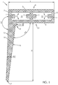
- the figure 1 represents, in section, a profile 1 for producing a frame 2 of a slab 3 false ceiling or false wall.
- an acute angle designates an angle whose value is strictly between 0 ° and 90 °
- an obtuse angle designates an angle whose value is strictly between 90 ° and 180 °.
- the profile 1 comprises a base 4 which has in section a substantially rectangular profile.
- This base 4 comprises a substantially horizontal upper wall 5 and a lower wall 6 parallel to the upper wall 5, connected at their ends by two parallel opposite walls, namely an inner wall 8 and an outer wall 7.
- the base 4 extends transversely over a width L, and is preferably hollow.
- the base 4 includes an intermediate wall 9 which divides the base 4 into two boxes 10.
- the boxes 10 are provided with projecting ribs 11 which define slides 12 each adapted to receive an assembly element 13 of the frame 2, in particular a bracket that comes to ioger in a slideway 12 to secure two adjacent sections 1.
- the profile 1 further comprises a side wall 14, which protrudes from the base 4 substantially in the extension of the outer wall 7.
- the side wall 14 has an outer face 15 which extends in the extension of the outer wall 7 of the base 4, and an inner face 16, which extends on the side of the lower wall 6 of the base 4.
- the external face extends slightly obliquely with respect to the vertical, and forms with the external wall 7 of the base 4 an open angle A1 which is strictly less than 180 ° while being greater than or equal to 170 °. According to one embodiment, the angle A1 is approximately 175 °.
- the inner face 16 also extends obliquely with respect to the vertical, on the same side as the external face, and forms with the bottom wall 6 of the base 4 an obtuse angle A2, strictly greater than 90 ° while preferably being less than 110 °.
- the angle A2 is about 100 °.
- the inner face 16 and the outer face 15 meet, opposite the base 4, at a lower end edge 17 of the side wall 14. This end edge 17 forms a support for the slab 2, as will be explained below.
- the end edge 17 is rounded to form a fillet of connection between the outer face 15 and the inner face 16.
- the lateral wall 14 extends over a height H, measured vertically between the bottom wall 6 of the base 4 and the end edge 17, equal to or greater than the width L of the base 4. According to one embodiment , the height H of the lateral wall 14 is equal to or greater than approximately 20% of the width L of the base 4.
- the profile 1 comprises, at the junction of the side wall 14 and the base 4, and more precisely at the junction of the inner face 16 and the lower wall 6 of the base, a rebate 18, one edge 19 internal forms a reference surface substantially perpendicular to the bottom wall 6 of the base 4.
- the rebate 18 extends, in the example shown, a height h, measured vertically from the lower wall 6 of the base 4, small in front of the height H of the side wall 14. According to one embodiment, the height h of the rabbet 18 is of the order of a few millimeters.
- the outer face and the inner face 16 of the side wall 14 form between them an acute angle A3 such that the side wall 14 appears tapered on the side of its end edge 17.
- the angle A3 is advantageously less than or equal to 10 °. According to an embodiment illustrated on the figure 1 the angle A3 is of the order of 5 °.
- the slab frame 2 is formed by assembling four sections 1 which terminate at their ends by miter cuts at 45 ° allowing, when two sections 1 are abutted, to make a right angle assembly.
- the assembly elements 13 are inserted into their slides 12 to ensure a rigid retention of the profiles 1 at their junctions.
- the frame 2 thus assembled then forms a housing 21 delimited vertically by the lower wall 6, and laterally by the rabbet 18 of each section 1.
- a luminous panel 22 is then attached by being positioned in the housing 21 thus defined, and fixed (for example by gluing, screwing, welding or riveting) on the lower wall 6 of the profiles 1.
- This luminous panel 22, which has a contour 23 to square or rectangular profile, carries a multitude of 24 light sources arranged in the form of a matrix and turned away from the base 4 when the panel 22 is mounted.
- these light sources 24 are light-emitting diodes (LEDs) each emitting a light according to a cone 25 whose half-angle at the vertex is denoted A4 ( figure 4 ).
- D denotes the predetermined distance between the contour 23 of the panel 22 and each source 24 closest to the contour 23 (that is to say the peripheral sources 24 of the matrix of sources 24).
- the inner edge 19 of the rabbet 18 allows to accurately position the panel 22 relative to each profile 1, and more precisely with respect to each side wall 14.
- the perpendicularity the internal edge 19 of the rabbet 18 ensures a good lateral wedging of the panel 22 relative to the frame 2.
- the contour 23 of the panel 22 is indeed positioned against the inner edge 19 of the rabbet 18, with a minimum clearance preferably, zero, so that, given the height H of the side wall 14 and the distance D, predetermined, the light cone of each source 24 adjacent the contour 23 is tangent to the end edge 17 of the side wall 14, as illustrated on the figure 4 .
- a fabric 26 is stretched on the frame 2.
- This fabric 26, typically made of PVC, is distended thermally (hot) to bag the frame 2.
- the free edge (s) of the fabric 26 is (are) then welded (s), and the fabric 26 is then cooled (possibly accelerated), this cooling accompanied by a narrowing of the fabric 26 which then comes to enclose the frame 2.
- a power supply cord of the luminous panel 22 passes through the fabric 26 to allow the connection of the luminous panel 22 to the sector.
- this crossing can advantageously be achieved by a manual recovery.
- the slab 3 is mounted on a support 27 fixed to the ceiling.
- This support 27 is particularly in the form of an L-beam or T-beam, comprising a vertical core 28 and a horizontal sole 29 which extends at right angles to a lower end of the core 28, this sole 29 defining a laying plan for the end edge 17.
- the sharpness of the end edge 17 makes it possible to reduce the width of the soleplate 29, and thus to reduce the area of shadow formed by this while the fabric 26 stretched, backlit by the panel 22 light, forms a square of diffuse light.
- the frame 2 does not cast any shadow on the fabric 26.
- Lighting causes the frame to overheat.
- the inclination of the outer face which restricts the contact surfaces between the frame 2 and the support 27 (in particular between the lateral wall 14 and the core 28), limits the heat transfer to the support 27, which which reduces the risk of deformation of the latter and allows better cooling the slab 3 by air circulation on its sides.
Description
L'invention se rapporte au domaine technique des faux plafonds suspendus ou des faux murs. L'invention concerne plus particulièrement une dalle de faux plafond. Une telle dalle comprend généralement un cadre et une toile tendue sur le cadre.The invention relates to the technical field of false suspended ceilings or false walls. The invention relates more particularly to a false ceiling slab. Such a slab generally includes a frame and a canvas stretched over the frame.
On connaît notamment du document
Ce profilé comporte une paroi supérieure, une paroi latérale composée d'une partie supérieure sensiblement perpendiculaire à la paroi supérieure et d'une partie inférieure formant un angle obtus avec la partie supérieure. Le profilé comprend, en outre, une paroi d'appui située en partie inférieure du profilé, une aile interne sensiblement perpendiculaire à la paroi supérieure et deux parois de rigidification. La première paroi de rigidification est sensiblement parallèle à la paroi supérieure et relie la partie supérieure de la paroi latérale avec l'aile interne, formant ainsi un premier caisson. La deuxième paroi de rigidification relie la paroi d'appui avec l'aile interne, formant ainsi un deuxième caisson.This profile has an upper wall, a side wall composed of an upper portion substantially perpendicular to the upper wall and a lower portion forming an obtuse angle with the upper part. The profile further comprises a bearing wall located in the lower part of the profile, an inner flange substantially perpendicular to the upper wall and two stiffening walls. The first stiffening wall is substantially parallel to the upper wall and connects the upper part of the side wall with the inner wing, thus forming a first box. The second stiffening wall connects the support wall with the inner wing, thus forming a second box.
De plus, l'aile interne comprend des gorges de montage aptes à solidariser des cornières sur lesquelles sont fixés, par exemple, des matériaux isolants ou des systèmes lumineux.In addition, the inner flange comprises mounting grooves adapted to secure brackets on which are fixed, for example, insulating materials or light systems.
Ce profilé donne satisfaction, notamment par sa résistance mécanique, mais demeure perfectible. D'une part, un cadre formé de tels profilés nécessite l'utilisation de cornières pour la fixation d'un dispositif d'éclairage ou d'un insert d'isolation phonique et/ou thermique, ce qui complexifie son procédé de montage.This profile gives satisfaction, particularly by its mechanical strength, but remains perfectible. On the one hand, a frame formed of such profiles requires the use of brackets for fixing a lighting device or a sound and / or thermal insulation insert, which complicates its mounting process.
D'autre part, un cadre formé au moyen de tels profilés peut être jugé lourd ou encombrant.On the other hand, a frame formed by such profiles can be considered heavy or bulky.
Un premier objectif est de proposer un profilé pour une dalle de faux plafond d'encombrement réduit.A first objective is to provide a profile for a false ceiling slab reduced size.
Un deuxième objectif est de proposer un profilé pour une dalle de faux plafond allégée.A second objective is to propose a profile for a slab of false ceiling lightened.
Un troisième objectif est de proposer un profilé pour une dalle de faux plafond offrant une tenue mécanique accrue à masse égale, ou une tenue mécanique maintenue à taille réduite.A third objective is to provide a profile for a false ceiling slab providing increased mechanical strength to equal mass, or mechanical strength maintained small size.
À cet effet, il est proposé, en premier lieu, un profilé pour la réalisation d'une dalle de faux plafond ou de faux mur, le cadre étant destiné à encadrer un panneau lumineux, le profilé comprenant :
- une embase sensiblement rectangulaire comportant une paroi supérieure et une paroi inférieure opposées reliées par une paroi externe et une paroi interne opposées ;
- une paroi latérale qui s'étend en saillie à partir de l'embase sensiblement dans le prolongement de la paroi externe, cette paroi latérale présentant une face externe et une face interne opposées ;
- a substantially rectangular base comprising an opposite upper wall and an opposing bottom wall connected by an opposite outer wall and an inner wall;
- a side wall which protrudes from the base substantially in the extension of the outer wall, this side wall having an opposite outer face and an inner face;
Diverses caractéristiques supplémentaires peuvent être prévues, seules ou en combinaison :
- la face interne de la paroi latérale forme, avec la paroi inférieure de l'embase, un angle obtus ;
- l'angle entre la face interne de la paroi latérale et la paroi inférieure de l'embase est compris strictement entre 90° et 110° ;
- l'angle entre la face interne de la paroi latérale et la paroi inférieure de l'embase est d'environ 97°;
- la face externe de la paroi latérale forme un angle obtus avec la paroi externe de l'embase ;
- l'angle entre la face externe de la paroi latérale et la paroi externe de l'embase est compris strictement entre 170° et 180 ;
- l'angle entre la face externe de la paroi latérale et la paroi externe de l'embase est de 177° environ ;
- la feuillure présente un bord interne qui s'étend, à partir de la paroi inférieure de l'embase, sur une hauteur de quelques millimètres ;
- l'embase du profilé est subdivisée en caissons dans lesquels sont définies des glissières pour des éléments d'assemblage.
- the inner face of the side wall forms, with the bottom wall of the base, an obtuse angle;
- the angle between the inner face of the side wall and the bottom wall of the base is strictly between 90 ° and 110 °;
- the angle between the inner face of the side wall and the bottom wall of the base is about 97 °;
- the outer face of the side wall forms an obtuse angle with the outer wall of the base;
- the angle between the outer face of the side wall and the outer wall of the base is strictly between 170 ° and 180;
- the angle between the outer face of the side wall and the outer wall of the base is approximately 177 °;
- the rabbet has an inner edge which extends, from the lower wall of the base, to a height of a few millimeters;
- the base of the profile is subdivided into boxes in which are defined slides for assembly elements.
Il est proposé, en deuxième lieu, une dalle de faux plafond ou de faux mur dans laquelle cette dalle comprend un cadre formé par assemblage de profilés tel que présenté ci dessus, une toile tendue sur le cadre, et un panneau lumineux monté sur l'embase des profilés, dans un logement délimité par la paroi inférieure et la feuillure de chaque profilé.It is proposed, secondly, a false ceiling slab or false wall in which this slab comprises a frame formed by assembling profiles as presented above, a canvas stretched over the frame, and a light panel mounted on the base of the profiles, in a housing delimited by the lower wall and the rabbet of each profile.
D'autres objets et avantages de l'invention apparaîtront à la lumière de la description d'un mode de réalisation, faite ci-après en référence aux dessins annexés dans lesquels :
- la
figure 1 est une vue en section du profilé; - la
figure 2 est une vue éclatée de dessous montrant une dalle de faux plafond ou de faux mur comportant un dispositif lumineux, pour des raisons de clarté, la toile de la dalle n'est pas représentée ; - la
figure 3 est une vue de détail selon l'encart III de lafigure 2 ; - la
figure 4 est une vue de détail en section d'une dalle de faux plafond ou de faux mur comprenant un dispositif lumineux.
- the
figure 1 is a sectional view of the section; - the
figure 2 is an exploded view from below showing a slab of false ceiling or false wall comprising a light device, for the sake of clarity, the fabric of the slab is not shown; - the
figure 3 is a detail view according to box III of thefigure 2 ; - the
figure 4 is a detailed sectional view of a false ceiling slab or false wall comprising a luminous device.
La
La description ci-après du profilé 1 est faite en référence à une utilisation pour une dalle de faux plafond, comme illustré en section sur la
Dans ce qui suit, un angle aigu désigne un angle dont la valeur est comprise strictement entre 0° et 90°; un angle obtus désigne un angle dont la valeur est comprise strictement entre 90° et 180°.In what follows, an acute angle designates an angle whose value is strictly between 0 ° and 90 °; an obtuse angle designates an angle whose value is strictly between 90 ° and 180 °.
Le profilé 1 comporte une embase 4 qui présente en section un profil sensiblement rectangulaire. Cette embase 4 comprend une paroi 5 supérieure sensiblement horizontale et une paroi 6 inférieure parallèle à la paroi 5 supérieure, reliées à leurs extrémités par deux parois opposées parallèles, à savoir une paroi 8 interne et une paroi 7 externe.The profile 1 comprises a
L'embase 4 s'étend transversalement sur une largeur L, et est de préférence creuse.The
Selon un mode de réalisation illustré sur les figures, l'embase 4 inclut une paroi 9 intermédiaire qui subdivise l'embase 4 en deux caissons 10. Comme on le voit sur les figures, et notamment sur la
Comme cela est bien visible sur les
La paroi 14 latérale présente une face 15 externe qui s'étend dans le prolongement de la paroi 7 externe de l'embase 4, et une face 16 interne, qui s'étend du côté de la paroi 6 inférieure de l'embase 4. Comme on le voit sur les
La face 16 interne s'étend également de manière oblique par rapport à la verticale, du même côté que la face 15 externe, et forme avec la paroi 6 inférieure de l'embase 4 un angle A2 obtus, strictement supérieur à 90° tout en étant de préférence inférieur à 110°.The
Selon un mode de réalisation, l'angle A2 est d'environ 100°.According to one embodiment, the angle A2 is about 100 °.
La face 16 interne et la face 15 externe se rejoignent, à l'opposé de l'embase 4, en un bord 17 d'extrémité inférieure de la paroi 14 latérale. Ce bord 17 d'extrémité forme support pour la dalle 2, comme cela sera expliqué ci-après.The
Selon un mode de réalisation, le bord 17 d'extrémité est arrondi pour former un congé de raccordement entre la face 15 externe et la face 16 interne.According to one embodiment, the
La paroi 14 latérale s'étend sur une hauteur H, mesurée verticalement entre la paroi 6 inférieure de l'embase 4 et le bord 17 d'extrémité, égale ou supérieure à la largeur L de l'embase 4. Selon un mode de réalisation, la hauteur H de la paroi 14 latérale est égale ou supérieure de 20% environ à la largeur L de l'embase 4.The
Comme on le voit sur les
La feuillure 18 s'étend, dans l'exemple illustré, sur une hauteur h, mesurée verticalement à partir de la paroi 6 inférieure de l'embase 4, faible devant la hauteur H de la paroi 14 latérale. Selon un mode de réalisation, la hauteur h de la feuillure 18 est de l'ordre de quelques millimètres.The
Comme on le voit bien sur la
Le cadre 2 de dalle est formé par assemblage de quatre profilés 1 qui se terminent à leurs extrémités par des coupes 20 d'onglets à 45° permettant, lorsque deux profilés 1 sont aboutés, de réaliser un assemblage à angle droit. Les éléments 13 d'assemblage sont insérés dans leurs glissières 12 pour assurer un maintien rigide des profilés 1 à leurs jonctions.The
Le cadre 2 ainsi assemblé forme alors un logement 21 délimité verticalement par la paroi 6 inférieure, et latéralement par la feuillure 18 de chaque profilé 1.The
Un panneau 22 lumineux est ensuite rapporté en étant positionné dans le logement 21 ainsi délimité, et fixé (par exemple par collage, vissage, soudage ou encore rivetage) sur la paroi 6 inférieure des profilés 1. Ce panneau 22 lumineux, qui présente un contour 23 à profil carré ou rectangulaire, porte une multitude de sources 24 lumineuses agencées sous forme d'une matrice et tournées à l'opposé de l'embase 4 lorsque le panneau 22 est monté. Selon un mode de réalisation, ces sources 24 lumineuses sont des diodes électroluminescentes (LED) émettant chacune une lumière selon un cône 25 dont le demi-angle au sommet est noté A4 (
On note D la distance, prédéterminée, entre le contour 23 du panneau 22 et chaque source 24 la plus proche du contour 23 (c'est-à-dire les sources 24 périphériques de la matrice de sources 24).D denotes the predetermined distance between the contour 23 of the
Le bord 19 interne de la feuillure 18 permet de positionner précisément le panneau 22 par rapport à chaque profilé 1, et plus précisément par rapport à chaque paroi 14 latérale. La perpendicularité du bord 19 interne de la feuillure 18 permet d'assurer un bon calage latéral du panneau 22 par rapport au cadre 2. Le contour 23 du panneau 22 vient en effet se positionner contre le bord 19 interne de la feuillure 18, avec un jeu minimum voire, de préférence, nul, de sorte que, compte tenu de la hauteur H de la paroi 14 latérale et de la distance D, prédéterminées, le cône 25 lumineux de chaque source 24 voisine du contour 23 soit tangent au bord 17 d'extrémité de la paroi 14 latérale, comme cela est illustré sur la
La feuillure 18, qui forme une saillie par rapport à la jonction entre la paroi 14 latérale et la paroi 8 interne de l'embase 4, peut subir une reprise d'usinage par fraisage lorsque son excroissance par rapport à la paroi 14 latérale est trop importante, comme illustré en pointillés sur la
Une fois le cadre 2 ainsi assemblé et le panneau 22 lumineux monté sur le cadre 2, une toile 26 est tendue sur le cadre 2. Cette toile 26, typiquement réalisée en PVC, est distendue par voie thermique (à chaud) pour venir ensacher le cadre 2. Le (ou les) bord(s) libre(s) de la toile 26 est (sont) ensuite soudé(s), et la toile 26 est ensuite refroidie (éventuellement de manière accélérée), ce refroidissement s'accompagnant d'un rétreint de la toile 26 qui vient alors enserrer le cadre 2.Once the
Avantageusement, un cordon d'alimentation électrique du panneau 22 lumineux traverse la toile 26 pour permettre le raccordement du panneau 22 lumineux au secteur. En fabrication, cette traversée peut avantageusement être réalisée par une reprise manuelle. La dalle 3 est montée sur un support 27 fixé au plafond. Ce support 27 se présente notamment sous forme d'une poutre en L ou en T, comprenant une âme 28 verticale et une semelle 29 horizontale qui s'étend à l'équerre à une extrémité inférieure de l'âme 28, cette semelle 29 définissant un plan de pose pour le bord 17 d'extrémité.Advantageously, a power supply cord of the
Le caractère pointu du bord 17 d'extrémité permet de réduire la largeur de la semelle 29, et de réduire ainsi la zone d'ombre formée par celle-ci tandis que la toile 26 tendue, rétroéclairée par le panneau 22 lumineux, forme un carré de lumière diffuse.The sharpness of the
Grâce à la tangence du cône 25 lumineux des sources 24 périphériques avec le bord 17 d'extrémité, le cadre 2 ne projette pas d'ombre sur la toile 26.Due to the tangency of the light cone of the
L'éclairage provoque un échauffement du cadre. Cependant, l'inclinaison de la face 15 externe, qui restreint les surfaces de contact entre le cadre 2 et le support 27 (en particulier entre la paroi 14 latérale et l'âme 28), limite la transmission de chaleur au support 27, ce qui réduit les risques de déformation de ce dernier et permet de mieux refroidir la dalle 3 par circulation d'air sur ses côtés.Lighting causes the frame to overheat. However, the inclination of the outer face, which restricts the contact surfaces between the
Claims (10)
- Profile (1) for creating a frame for a tile of a false ceiling or false wall, the frame being intended to surround a lighting panel, the profile (1) comprising:- a substantially rectangular base (4) comprising an upper wall (5) and a lower wall (6) which are opposite one another and connected by an external wall (7) and an internal wall (8) which are opposite one another;- a lateral wall (14) which projects out from the base (4) substantially in the continuation of the external wall (7), this lateral wall (14) having an external face (15) and an internal face (16) which are opposite one another;characterized in that the profile (1) comprises a rebate (18) where the internal face (16) of the lateral wall (14) and the lower wall (6) of the base (4) meet, this rebate (18) having an internal edge (19) substantially perpendicular to the lower wall (6) of the base (4), this rebate (18) being able to house and hold in position the lighting panel (22) that can be mounted on the base of the profile.
- Profile (1) according to Claim 1, characterized in that the internal face (16) of the lateral wall (14) forms with the lower wall (6) of the base (4), an obtuse angle A2.
- Profile (1) according to Claim 2, characterized in that the angle A2 between the internal face (16) of the lateral wall (14) and the lower wall (6) of the base (4) is strictly comprised between 90° and 110°.
- Profile (1) according to Claim 3, characterized in that the angle A2 between the internal face (16) of the lateral wall (14) and the lower wall (6) of the base (4) is around 97°.
- Profile according to any one of the preceding claims, characterized in that the external face (15) of the lateral wall (14) forms an obtuse angle A1 with the external wall (7) of the base (4).
- Profile according to Claim 5, characterized in that the angle A1 between the external face (15) of the lateral wall (14) and the external wall (7) of the base (4) is strictly comprised between 170° and 180°.
- Profile according to Claim 6, characterized in that the angle A1 between the external face (15) of the lateral wall (14) and the external wall (7) of the base (4) is around 177°.
- Profile according to any one of the preceding claims, characterized in that the rebate (18) has an internal edge (19) which extends, from the lower wall (6) of the base (4), over a height h of a few millimetres.
- Profile according to any one of the preceding claims, characterized in that the base (4) is subdivides into compartments (10) in which guideways (12) for assembly elements are defined.
- False-ceiling or false-wall tile (3), characterized in that this tile (3) comprises a frame (2) formed by assembling profiles (1) according to one of the preceding claims, a fabric (26) stretched over the frame (2), and a lighting panel (22) mounted on the base (4) of the profiles (1), in a housing (21) delimited by the lower wall (6) and the rebate (18) of each profile (1).
Applications Claiming Priority (2)
| Application Number | Priority Date | Filing Date | Title |
|---|---|---|---|
| FR1351746A FR3002566B1 (en) | 2013-02-27 | 2013-02-27 | ARRAY PROFILE FOR THE CONSTRUCTION OF A FRAME OF FALSE CEILING OR FALSE WALL |
| PCT/FR2014/050407 WO2014131988A1 (en) | 2013-02-27 | 2014-02-25 | Swept section piece for constructing a false-ceiling or false-wall slab surround |
Publications (2)
| Publication Number | Publication Date |
|---|---|
| EP2961897A1 EP2961897A1 (en) | 2016-01-06 |
| EP2961897B1 true EP2961897B1 (en) | 2018-06-06 |
Family
ID=48652257
Family Applications (1)
| Application Number | Title | Priority Date | Filing Date |
|---|---|---|---|
| EP14713185.8A Not-in-force EP2961897B1 (en) | 2013-02-27 | 2014-02-25 | Acute framework profile for forming a panel of a false ceiling or wall |
Country Status (3)
| Country | Link |
|---|---|
| EP (1) | EP2961897B1 (en) |
| FR (1) | FR3002566B1 (en) |
| WO (1) | WO2014131988A1 (en) |
Families Citing this family (2)
| Publication number | Priority date | Publication date | Assignee | Title |
|---|---|---|---|---|
| FR3053987B1 (en) * | 2016-07-13 | 2021-06-18 | Normalu | FALSE CEILING INCLUDING MEANS FOR SHIMMING PANELS AND PROCESS FOR THE REALIZATION OF SUCH FALSE CEILING |
| FR3140638A1 (en) | 2022-10-05 | 2024-04-12 | Newmat | Profiled element for stretched canvas slab and slab comprising such a profiled element |
Family Cites Families (4)
| Publication number | Priority date | Publication date | Assignee | Title |
|---|---|---|---|---|
| CH384823A (en) * | 1960-02-26 | 1965-02-26 | Gema Ag Apparatebau Und Stanze | Ceiling construction with light insert |
| FR2789101B1 (en) * | 1999-01-29 | 2001-03-02 | Jean Marc Scherrer | CEILING SLAB |
| FR2892739B1 (en) | 2005-11-03 | 2008-01-18 | Newmat Sa Sa | PROFILE FOR EMPTY FRAME |
| FR2970013B1 (en) * | 2010-12-30 | 2013-11-15 | Normalu | FALSE DEVICE WITH TRIPLE THICKNESS |
-
2013
- 2013-02-27 FR FR1351746A patent/FR3002566B1/en not_active Expired - Fee Related
-
2014
- 2014-02-25 EP EP14713185.8A patent/EP2961897B1/en not_active Not-in-force
- 2014-02-25 WO PCT/FR2014/050407 patent/WO2014131988A1/en active Application Filing
Also Published As
| Publication number | Publication date |
|---|---|
| WO2014131988A1 (en) | 2014-09-04 |
| FR3002566B1 (en) | 2018-02-16 |
| EP2961897A1 (en) | 2016-01-06 |
| FR3002566A1 (en) | 2014-08-29 |
Similar Documents
| Publication | Publication Date | Title |
|---|---|---|
| EP1783292B1 (en) | Profile for a ceiling slab frame, in particular for a frame to be pocketed | |
| FR2936263A1 (en) | STRUCTURE CONSISTING OF THE ASSEMBLY OF AT LEAST TWO ELEMENTS OF CONSTRUCTION | |
| FR2961300A1 (en) | STRUCTURE FOR SOLIDARIZING PHOTOVOLTAIC PANELS ON A BUILDING | |
| CA2731788C (en) | Profile bowing means for a sinking surround | |
| EP0288376B1 (en) | Fixing device for the plates of a façade cladding | |
| EP2961897B1 (en) | Acute framework profile for forming a panel of a false ceiling or wall | |
| FR2950371A1 (en) | Primarily parallelepiped flagstones attaching unit for construction of terrace, has support parts solidarized for support structures, and elastically deformable clips arranged primarily with respect to each other in perpendicular direction | |
| EP2494120B1 (en) | Fixing system for a false wall having guided clamping | |
| CA2973677A1 (en) | Device for attaching a solar panel | |
| EP2683885B1 (en) | Universal profile member | |
| EP1024232B1 (en) | Ceiling board | |
| EP2596186B1 (en) | Structure for attaching wall cladding and associated wall assembly | |
| FR2878875A1 (en) | Module e.g. slab, for lining wall or ceiling, has frame whose lateral sides cooperate with positioning unit connected on profile, where height of unit is equal to that of plane surface supporting against unit with self-adhesive side | |
| EP0854245B1 (en) | Structure of an externally insulated construction and a construction employing such a structure | |
| EP2607564B3 (en) | Rail for false-wall frame, in particular of a suspended ceiling | |
| FR2941725A1 (en) | Parallelepiped block shaped thermal insulation element for construction block of e.g. longitudinal wall of concrete floor in building, has openings formed from lower and outer faces to open into housing to define assembling wall with block | |
| FR2931497A1 (en) | METALLIC PROFILE | |
| EP1404933A1 (en) | Device for assembling panels, laths or sheathings with load distribution | |
| FR3052753A1 (en) | DEVICE FOR STORING AND PACKAGING OBJECTS | |
| FR2843142A1 (en) | Double wall false ceiling consists of superposed canvases stretched on rails fixed to wall, rails comprising profiled element having vertical wall with hooking means in upper and lower parts for tensioned holding of canvases | |
| FR2997112A1 (en) | Skirting panel for formation of false ceiling, has stop groove for receiving head of stopper for fixing to support beam, where lower lip is longer than upper lip and covers half of width of beam to make beam to be invisible | |
| FR2948444A1 (en) | Furnace for decorative chimney placed e.g. against partition in room, has segment including end border folded along concave form towards interior of segment, where border and another end border have shape of flanges/pads separated by slot | |
| FR2703093A3 (en) | Combined supports of ducts and brackets in a reinforced concrete slab | |
| FR3053987A1 (en) | FALSE CEILING COMPRISING MEANS FOR LAYING PANELS AND METHOD FOR PRODUCING SUCH A FALSE CEILING | |
| EP1640528A1 (en) | Supporting plate for a corner post of a guardrail |
Legal Events
| Date | Code | Title | Description |
|---|---|---|---|
| PUAI | Public reference made under article 153(3) epc to a published international application that has entered the european phase |
Free format text: ORIGINAL CODE: 0009012 |
|
| 17P | Request for examination filed |
Effective date: 20150717 |
|
| AK | Designated contracting states |
Kind code of ref document: A1 Designated state(s): AL AT BE BG CH CY CZ DE DK EE ES FI FR GB GR HR HU IE IS IT LI LT LU LV MC MK MT NL NO PL PT RO RS SE SI SK SM TR |
|
| AX | Request for extension of the european patent |
Extension state: BA ME |
|
| DAX | Request for extension of the european patent (deleted) | ||
| GRAP | Despatch of communication of intention to grant a patent |
Free format text: ORIGINAL CODE: EPIDOSNIGR1 |
|
| STAA | Information on the status of an ep patent application or granted ep patent |
Free format text: STATUS: GRANT OF PATENT IS INTENDED |
|
| INTG | Intention to grant announced |
Effective date: 20180119 |
|
| RIN1 | Information on inventor provided before grant (corrected) |
Inventor name: COUSIN, ETIENNE |
|
| GRAS | Grant fee paid |
Free format text: ORIGINAL CODE: EPIDOSNIGR3 |
|
| GRAA | (expected) grant |
Free format text: ORIGINAL CODE: 0009210 |
|
| STAA | Information on the status of an ep patent application or granted ep patent |
Free format text: STATUS: THE PATENT HAS BEEN GRANTED |
|
| AK | Designated contracting states |
Kind code of ref document: B1 Designated state(s): AL AT BE BG CH CY CZ DE DK EE ES FI FR GB GR HR HU IE IS IT LI LT LU LV MC MK MT NL NO PL PT RO RS SE SI SK SM TR |
|
| REG | Reference to a national code |
Ref country code: GB Ref legal event code: FG4D Free format text: NOT ENGLISH |
|
| REG | Reference to a national code |
Ref country code: CH Ref legal event code: EP Ref country code: AT Ref legal event code: REF Ref document number: 1006255 Country of ref document: AT Kind code of ref document: T Effective date: 20180615 |
|
| REG | Reference to a national code |
Ref country code: IE Ref legal event code: FG4D Free format text: LANGUAGE OF EP DOCUMENT: FRENCH |
|
| REG | Reference to a national code |
Ref country code: DE Ref legal event code: R096 Ref document number: 602014026617 Country of ref document: DE |
|
| REG | Reference to a national code |
Ref country code: NL Ref legal event code: MP Effective date: 20180606 |
|
| REG | Reference to a national code |
Ref country code: LT Ref legal event code: MG4D |
|
| PG25 | Lapsed in a contracting state [announced via postgrant information from national office to epo] |
Ref country code: ES Free format text: LAPSE BECAUSE OF FAILURE TO SUBMIT A TRANSLATION OF THE DESCRIPTION OR TO PAY THE FEE WITHIN THE PRESCRIBED TIME-LIMIT Effective date: 20180606 Ref country code: SE Free format text: LAPSE BECAUSE OF FAILURE TO SUBMIT A TRANSLATION OF THE DESCRIPTION OR TO PAY THE FEE WITHIN THE PRESCRIBED TIME-LIMIT Effective date: 20180606 Ref country code: LT Free format text: LAPSE BECAUSE OF FAILURE TO SUBMIT A TRANSLATION OF THE DESCRIPTION OR TO PAY THE FEE WITHIN THE PRESCRIBED TIME-LIMIT Effective date: 20180606 Ref country code: NO Free format text: LAPSE BECAUSE OF FAILURE TO SUBMIT A TRANSLATION OF THE DESCRIPTION OR TO PAY THE FEE WITHIN THE PRESCRIBED TIME-LIMIT Effective date: 20180906 Ref country code: FI Free format text: LAPSE BECAUSE OF FAILURE TO SUBMIT A TRANSLATION OF THE DESCRIPTION OR TO PAY THE FEE WITHIN THE PRESCRIBED TIME-LIMIT Effective date: 20180606 Ref country code: CY Free format text: LAPSE BECAUSE OF FAILURE TO SUBMIT A TRANSLATION OF THE DESCRIPTION OR TO PAY THE FEE WITHIN THE PRESCRIBED TIME-LIMIT Effective date: 20180606 Ref country code: BG Free format text: LAPSE BECAUSE OF FAILURE TO SUBMIT A TRANSLATION OF THE DESCRIPTION OR TO PAY THE FEE WITHIN THE PRESCRIBED TIME-LIMIT Effective date: 20180906 |
|
| PG25 | Lapsed in a contracting state [announced via postgrant information from national office to epo] |
Ref country code: GR Free format text: LAPSE BECAUSE OF FAILURE TO SUBMIT A TRANSLATION OF THE DESCRIPTION OR TO PAY THE FEE WITHIN THE PRESCRIBED TIME-LIMIT Effective date: 20180907 Ref country code: RS Free format text: LAPSE BECAUSE OF FAILURE TO SUBMIT A TRANSLATION OF THE DESCRIPTION OR TO PAY THE FEE WITHIN THE PRESCRIBED TIME-LIMIT Effective date: 20180606 Ref country code: LV Free format text: LAPSE BECAUSE OF FAILURE TO SUBMIT A TRANSLATION OF THE DESCRIPTION OR TO PAY THE FEE WITHIN THE PRESCRIBED TIME-LIMIT Effective date: 20180606 Ref country code: HR Free format text: LAPSE BECAUSE OF FAILURE TO SUBMIT A TRANSLATION OF THE DESCRIPTION OR TO PAY THE FEE WITHIN THE PRESCRIBED TIME-LIMIT Effective date: 20180606 |
|
| REG | Reference to a national code |
Ref country code: AT Ref legal event code: MK05 Ref document number: 1006255 Country of ref document: AT Kind code of ref document: T Effective date: 20180606 |
|
| PG25 | Lapsed in a contracting state [announced via postgrant information from national office to epo] |
Ref country code: NL Free format text: LAPSE BECAUSE OF FAILURE TO SUBMIT A TRANSLATION OF THE DESCRIPTION OR TO PAY THE FEE WITHIN THE PRESCRIBED TIME-LIMIT Effective date: 20180606 |
|
| PG25 | Lapsed in a contracting state [announced via postgrant information from national office to epo] |
Ref country code: SK Free format text: LAPSE BECAUSE OF FAILURE TO SUBMIT A TRANSLATION OF THE DESCRIPTION OR TO PAY THE FEE WITHIN THE PRESCRIBED TIME-LIMIT Effective date: 20180606 Ref country code: AT Free format text: LAPSE BECAUSE OF FAILURE TO SUBMIT A TRANSLATION OF THE DESCRIPTION OR TO PAY THE FEE WITHIN THE PRESCRIBED TIME-LIMIT Effective date: 20180606 Ref country code: EE Free format text: LAPSE BECAUSE OF FAILURE TO SUBMIT A TRANSLATION OF THE DESCRIPTION OR TO PAY THE FEE WITHIN THE PRESCRIBED TIME-LIMIT Effective date: 20180606 Ref country code: PL Free format text: LAPSE BECAUSE OF FAILURE TO SUBMIT A TRANSLATION OF THE DESCRIPTION OR TO PAY THE FEE WITHIN THE PRESCRIBED TIME-LIMIT Effective date: 20180606 Ref country code: IS Free format text: LAPSE BECAUSE OF FAILURE TO SUBMIT A TRANSLATION OF THE DESCRIPTION OR TO PAY THE FEE WITHIN THE PRESCRIBED TIME-LIMIT Effective date: 20181006 Ref country code: RO Free format text: LAPSE BECAUSE OF FAILURE TO SUBMIT A TRANSLATION OF THE DESCRIPTION OR TO PAY THE FEE WITHIN THE PRESCRIBED TIME-LIMIT Effective date: 20180606 Ref country code: CZ Free format text: LAPSE BECAUSE OF FAILURE TO SUBMIT A TRANSLATION OF THE DESCRIPTION OR TO PAY THE FEE WITHIN THE PRESCRIBED TIME-LIMIT Effective date: 20180606 |
|
| PG25 | Lapsed in a contracting state [announced via postgrant information from national office to epo] |
Ref country code: IT Free format text: LAPSE BECAUSE OF FAILURE TO SUBMIT A TRANSLATION OF THE DESCRIPTION OR TO PAY THE FEE WITHIN THE PRESCRIBED TIME-LIMIT Effective date: 20180606 Ref country code: SM Free format text: LAPSE BECAUSE OF FAILURE TO SUBMIT A TRANSLATION OF THE DESCRIPTION OR TO PAY THE FEE WITHIN THE PRESCRIBED TIME-LIMIT Effective date: 20180606 |
|
| REG | Reference to a national code |
Ref country code: DE Ref legal event code: R097 Ref document number: 602014026617 Country of ref document: DE |
|
| PLBE | No opposition filed within time limit |
Free format text: ORIGINAL CODE: 0009261 |
|
| STAA | Information on the status of an ep patent application or granted ep patent |
Free format text: STATUS: NO OPPOSITION FILED WITHIN TIME LIMIT |
|
| 26N | No opposition filed |
Effective date: 20190307 |
|
| PG25 | Lapsed in a contracting state [announced via postgrant information from national office to epo] |
Ref country code: DK Free format text: LAPSE BECAUSE OF FAILURE TO SUBMIT A TRANSLATION OF THE DESCRIPTION OR TO PAY THE FEE WITHIN THE PRESCRIBED TIME-LIMIT Effective date: 20180606 Ref country code: SI Free format text: LAPSE BECAUSE OF FAILURE TO SUBMIT A TRANSLATION OF THE DESCRIPTION OR TO PAY THE FEE WITHIN THE PRESCRIBED TIME-LIMIT Effective date: 20180606 |
|
| REG | Reference to a national code |
Ref country code: DE Ref legal event code: R119 Ref document number: 602014026617 Country of ref document: DE |
|
| REG | Reference to a national code |
Ref country code: CH Ref legal event code: PL |
|
| GBPC | Gb: european patent ceased through non-payment of renewal fee |
Effective date: 20190225 |
|
| PG25 | Lapsed in a contracting state [announced via postgrant information from national office to epo] |
Ref country code: LU Free format text: LAPSE BECAUSE OF NON-PAYMENT OF DUE FEES Effective date: 20190225 Ref country code: MC Free format text: LAPSE BECAUSE OF FAILURE TO SUBMIT A TRANSLATION OF THE DESCRIPTION OR TO PAY THE FEE WITHIN THE PRESCRIBED TIME-LIMIT Effective date: 20180606 |
|
| REG | Reference to a national code |
Ref country code: BE Ref legal event code: MM Effective date: 20190228 |
|
| REG | Reference to a national code |
Ref country code: IE Ref legal event code: MM4A |
|
| PG25 | Lapsed in a contracting state [announced via postgrant information from national office to epo] |
Ref country code: AL Free format text: LAPSE BECAUSE OF FAILURE TO SUBMIT A TRANSLATION OF THE DESCRIPTION OR TO PAY THE FEE WITHIN THE PRESCRIBED TIME-LIMIT Effective date: 20180606 |
|
| PG25 | Lapsed in a contracting state [announced via postgrant information from national office to epo] |
Ref country code: LI Free format text: LAPSE BECAUSE OF NON-PAYMENT OF DUE FEES Effective date: 20190228 Ref country code: CH Free format text: LAPSE BECAUSE OF NON-PAYMENT OF DUE FEES Effective date: 20190228 |
|
| PG25 | Lapsed in a contracting state [announced via postgrant information from national office to epo] |
Ref country code: IE Free format text: LAPSE BECAUSE OF NON-PAYMENT OF DUE FEES Effective date: 20190225 Ref country code: DE Free format text: LAPSE BECAUSE OF NON-PAYMENT OF DUE FEES Effective date: 20190903 Ref country code: GB Free format text: LAPSE BECAUSE OF NON-PAYMENT OF DUE FEES Effective date: 20190225 |
|
| PG25 | Lapsed in a contracting state [announced via postgrant information from national office to epo] |
Ref country code: BE Free format text: LAPSE BECAUSE OF NON-PAYMENT OF DUE FEES Effective date: 20190228 Ref country code: FR Free format text: LAPSE BECAUSE OF NON-PAYMENT OF DUE FEES Effective date: 20190228 |
|
| PG25 | Lapsed in a contracting state [announced via postgrant information from national office to epo] |
Ref country code: TR Free format text: LAPSE BECAUSE OF FAILURE TO SUBMIT A TRANSLATION OF THE DESCRIPTION OR TO PAY THE FEE WITHIN THE PRESCRIBED TIME-LIMIT Effective date: 20180606 |
|
| PG25 | Lapsed in a contracting state [announced via postgrant information from national office to epo] |
Ref country code: MT Free format text: LAPSE BECAUSE OF FAILURE TO SUBMIT A TRANSLATION OF THE DESCRIPTION OR TO PAY THE FEE WITHIN THE PRESCRIBED TIME-LIMIT Effective date: 20180606 Ref country code: PT Free format text: LAPSE BECAUSE OF FAILURE TO SUBMIT A TRANSLATION OF THE DESCRIPTION OR TO PAY THE FEE WITHIN THE PRESCRIBED TIME-LIMIT Effective date: 20181008 |
|
| PG25 | Lapsed in a contracting state [announced via postgrant information from national office to epo] |
Ref country code: HU Free format text: LAPSE BECAUSE OF FAILURE TO SUBMIT A TRANSLATION OF THE DESCRIPTION OR TO PAY THE FEE WITHIN THE PRESCRIBED TIME-LIMIT; INVALID AB INITIO Effective date: 20140225 |
|
| PG25 | Lapsed in a contracting state [announced via postgrant information from national office to epo] |
Ref country code: MK Free format text: LAPSE BECAUSE OF FAILURE TO SUBMIT A TRANSLATION OF THE DESCRIPTION OR TO PAY THE FEE WITHIN THE PRESCRIBED TIME-LIMIT Effective date: 20180606 |