EP2682921A1 - Bezahlterminal - Google Patents
Bezahlterminal Download PDFInfo
- Publication number
- EP2682921A1 EP2682921A1 EP12174750.5A EP12174750A EP2682921A1 EP 2682921 A1 EP2682921 A1 EP 2682921A1 EP 12174750 A EP12174750 A EP 12174750A EP 2682921 A1 EP2682921 A1 EP 2682921A1
- Authority
- EP
- European Patent Office
- Prior art keywords
- tablet
- payment terminal
- docking station
- printer
- connection
- Prior art date
- Legal status (The legal status is an assumption and is not a legal conclusion. Google has not performed a legal analysis and makes no representation as to the accuracy of the status listed.)
- Granted
Links
Images




Classifications
-
- G—PHYSICS
- G07—CHECKING-DEVICES
- G07G—REGISTERING THE RECEIPT OF CASH, VALUABLES, OR TOKENS
- G07G1/00—Cash registers
- G07G1/0018—Constructional details, e.g. of drawer, printing means, input means
-
- G—PHYSICS
- G07—CHECKING-DEVICES
- G07F—COIN-FREED OR LIKE APPARATUS
- G07F7/00—Mechanisms actuated by objects other than coins to free or to actuate vending, hiring, coin or paper currency dispensing or refunding apparatus
- G07F7/08—Mechanisms actuated by objects other than coins to free or to actuate vending, hiring, coin or paper currency dispensing or refunding apparatus by coded identity card or credit card or other personal identification means
- G07F7/0873—Details of the card reader
- G07F7/088—Details of the card reader the card reader being part of the point of sale [POS] terminal or electronic cash register [ECR] itself
- G07F7/0886—Details of the card reader the card reader being part of the point of sale [POS] terminal or electronic cash register [ECR] itself the card reader being portable for interacting with a POS or ECR in realizing a payment transaction
-
- G—PHYSICS
- G07—CHECKING-DEVICES
- G07G—REGISTERING THE RECEIPT OF CASH, VALUABLES, OR TOKENS
- G07G1/00—Cash registers
- G07G1/0036—Checkout procedures
- G07G1/0045—Checkout procedures with a code reader for reading of an identifying code of the article to be registered, e.g. barcode reader or radio-frequency identity [RFID] reader
- G07G1/0081—Checkout procedures with a code reader for reading of an identifying code of the article to be registered, e.g. barcode reader or radio-frequency identity [RFID] reader the reader being a portable scanner or data reader
Definitions
- the invention relates to a payment terminal for cashless payment.
- Payment terminals for cashless payment are used in particular in retail outlets or catering establishments. While the payment terminals in catering establishments are often portable, the payment terminals are usually fixed at the cash desks of retail outlets.
- Known payment terminals usually have a card reader for reading a magnetic stripe and / or chip card, for example a debit card, a keyboard for entering the PIN, a display and an integrated printer for printing receipts.
- the individual components are arranged as a single device within a common housing.
- the fixed payment terminals of cash desks are connected by cable with other devices of the cash desk workstation for power supply and data transmission. So that the fixed payment terminals can be served by both the cashier and the customer, they are rotatably mounted about a vertically extending axis of rotation.
- other devices such as a monitor, a keyboard, a computer, a goods scanner, a cash drawer and / or a customer display for the display of Information to be available to the customer.
- These individual devices are wired together for data transmission and power supply via appropriate cables and have a lot of space.
- the document WO 02/09054 A2 is a mobile payment terminal known.
- the document WO 2011/148168 A2 discloses a payment terminal in which the card reader is integrated into the housing of a tablet PC.
- the payment terminal comprises a tablet PC and a docking station for holding this tablet PC.
- the tablet PC is here about a solvable and recoverable mechanical connection to the docking station fastened.
- the tablet PC has a touch screen for entering information and displaying information to an operator of the payment terminal.
- the modular design of the payment terminal from a tablet PC and a docking station, which are connected to each other via a detachable and recoverable connection, ensures that this payment terminal can be used both as a mobile and as a stationary payment terminal.
- the tablet PC can be detached from the docking station and thus be carried, for example, in a catering business to the customer's place.
- the payment terminal is held at the docking station via the mechanical connection.
- the use of a tablet PC with a touch screen allows the payment terminal to be easily assembled from standard components and ensures a very comfortable and easy handling.
- the tablet PC preferably further comprises at least one accumulator for supplying the tablet PC with electrical energy.
- At the docking station and the tablet PC when the tablet PC is attached via the mechanical connection to the docking station, an electrical connection for recharging the battery is formed. This ensures that the tablet PC can be easily loaded when it is received in the docking station, that is, during the fixed operation of the payment terminal. Further allows the accumulator that the tablet PC while mobile payments, so if it is solved by the docking station, still supplied with electrical energy.
- the detachable and recoverable mechanical connection is designed in particular as a latching and / or plug-in connection, for which purpose the tablet PC in particular comprises a first latching element and the docking station has a second detent element formed complementary thereto, which engage in one another for producing a mechanical connection.
- the tablet PC can also be attached to each other by a technical layman without tools and again separated from each other.
- the mechanical connection is in particular designed in such a way that a tablet PC fastened via the mechanical connection to the docking station can be pivoted about a pivot axis so that a display area of the touch screen can optionally be used by a cashier or a customer, depending on the pivoting of the tablet PC.
- a display area of the touch screen can optionally be used by a cashier or a customer, depending on the pivoting of the tablet PC.
- the mechanical connection is designed in particular as a rocker bearing, by which the tablet PC can be tilted relative to the docking station similar to a rocker about the pivot axis.
- Such pivoting or tilting has compared to the known turning the advantage that the movement must be made only to a much smaller angle and a corresponding rocker bearing can be made much simpler.
- the tablet PC is pivotable in particular by an angle in the range between 30 ° and 90 °, so that the display area can be viewed by both the customer and the cashier in an ergonomically advantageous manner.
- the pivot axis is arranged horizontally in the normal operating arrangement of the docking station, ie in the arrangement in which the docking station is arranged during scheduled operation.
- the tablet PC comprises a first electrical contact and the docking station has a second electrical contact which is complementary to this first electrical contact, wherein a contacting between the first and the second electrical contact takes place automatically when the mechanical connection is made that the electrical connection between the docking station and the tablet PC is formed. This ensures that when attaching the tablet PC to the docking station automatically necessary for charging the battery of the tablet PC electrical connection is made and ensures that the tablet PC is loaded.
- the tablet PC in particular has at least one card reading unit for reading a magnetic stripe and / or chip card. It is particularly advantageous if the tablet PC comprises two card reading units, the first of these two card reading units being designed as a plug-in card reading unit for inserting a chip card to be read and the second of the two card reading units being designed as a card reading unit for pulling through a magnetic stripe card to be read.
- the card reading unit or the two card reading units are arranged in particular in the housing of the tablet PC, so that a simple space-saving construction is formed.
- the card reading units can for example also be arranged hinged and / or retractable, so that the space requirement is further reduced.
- the payment terminal comprises a mobile printer for printing receipts, this printer comprising a receiver and the tablet PC a transmitter, so that a wireless data transmission connection between the tablet PC and the printer can be formed.
- this wireless data transmission connection is in particular a Bluetooth connection.
- the docking station comprises a receiving area for receiving at least a part of the printer. Between the docking station and the printer is an electrical connection for charging a battery formed of the printer when the printer is included in this recording area.
- the printer is mobile on the one hand and thus can be arranged remotely from the docking station, depending on how the workstation requires it, but on the other hand charging of the accumulator of the mobile printer can be done easily via the docking station. In particular, therefore, the printer does not need to be connected via a cable to the mains.
- the tablet PC has on the opposite side of the display area, ie its back, in particular a fastener for attaching a further accumulator for supplying the tablet PC with electrical energy. This ensures that the operating time of the tablet PC without having to be charged, is increased.
- This additional accumulator can be fastened in particular to a handle.
- the fastening element, to which the further accumulator can be fastened to the tablet PC is designed in particular in such a way that the accumulator can be attached, in particular flanged, to the tablet PC via a detachable and recoverable connection.
- the docking station has an accumulator receiving area in which a furthermostakkumulator for the tablet PC can be added, this accumulator receiving area is designed such that a recorded in him canakkumulator can also be loaded via the docking station.
- the provision of a battery receiving area for receiving this additional replacement battery also has the advantage that a particularly space-saving design is achieved.
- the detachable and recoverable connection via which the tablet PC can be fastened to the docking station, is mechanically lockable, in particular via a locking element, so that the tablet PC can not simply be snatched away by an unauthorized person.
- the tablet PC has in particular a memory element, a camera, a barcode reader, a loudspeaker, a position sensor and / or a transmitting and / or receiving unit for transmitting or receiving data, for example Bluetooth, Wi-Fi, NFC and / or RFID, up.
- the tablet PC can be used not only for the payment terminal, but also for replacing other devices of the cashier's desk.
- a goods scanner for the docking station, a goods scanner, a cash drawer, a printer, a Customer display and / or a display for the cashier be provided.
- rocker bearing is designed such that the tablet PC engages in predetermined end positions, wherein it is assigned to the customer in one of these end positions and in the other end position the cashier. This locking ensures secure holding of the tablet PC even when operating, ie "touching" the touchscreen.
- the plug-in and / or latching elements are in particular designed such that different sized tablet PCs can be attached to the docking station, for example tablet PCs with seven inches and ten inches in diameter.
- a wireless data transmission connection for example a Bluetooth connection
- the printer is in particular connected to the docking station via a wired or wireless data transmission connection and receives the print jobs of the tablet PC via the docking station.
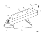
- Fig.1 is a schematic perspective view of a payment terminal 100 according to a first embodiment shown in the assembled state.
- Fig.2 shows a schematic, perspective view of this payment terminal 100 in the disassembled state, so that the individual easily assembled components of the payment terminal 100 are clearly visible.
- the payment terminal 100 comprises a tablet PC 12 and a docking station 14, to which the tablet PC 12 can be fastened for holding via a releasable and recoverable mechanical connection. Further, the payment terminal 100 has a mobile printer 16 for printing receipts 18.
- the tablet PC has two first latching elements, one of which is designated by the reference numeral 20.
- the docking station 14 has two complementary to the first locking elements formed second locking elements 22, wherein the first and the second locking elements 20, 22 engage in the manufacture of the releasable and recoverable connection with each other.
- the second locking elements 22 are provided in particular as elevations and the first locking elements 20 as correspondingly complementary recesses, so that a simple engagement for connecting the tablet PC 12 in the docking station 14 is possible and the tablet PC 12 is tilted relative to the docking station.
- This locking connection is in particular designed such that it is formed by a rocker bearing, so that the tablet PC 12 is pivotable about a pivot axis relative to the docking station 14 when it is attached to the docking station 14.
- This pivot axis is defined in particular by the connection of the centers of the contact areas between the first and the second locking elements 20, 22 and is in the planned orientation of the payment terminal 100, as this is used in operation, directed horizontally.
- This rocker bearing is enabled that the tablet PC 12 can be tilted relative to the docking station 14, so that it, as later in connection with the Figure 5 and 6 explained in more detail, either a cash-flow and a customer can be turned.
- the tablet PC 12 has a touch screen 24, over which information can be displayed.
- a virtual keyboard can be displayed via the touchscreen 24, via which the customer can enter the PIN number during cashless payments.
- the tablet PC 12 also has at least one card reading unit 26 for reading a magnetic stripe and / or chip card 28.
- This magnetic stripe and / or chip card 28 is, for example, a debit card or credit card, with which the customer can pay cashless .
- the card reading unit 26 is particularly in the housing of the tablet PC 12 integrated and / or arranged submerged and / or pivotally on this. It is particularly advantageous if two card reading units 26 are provided, wherein one of these card reading units is designed as a plug-in card reading unit and the other as a pass card reading unit.
- the card reading unit 26 is arranged on the head side of the tablet PC. Alternatively, however, the card reading unit can also be arranged on the side of the tablet PC 12.
- the docking station 14 serves in addition to holding in particular also for charging a battery of the tablet PC 12.
- the tablet PC 12 in particular at least a first electrical contact and the docking station 14 at least one complementarily formed second electrical contact, said electrical contacts preferably are arranged on the elements 20, 22, so that when the tablet PC is held at the docking station 14 via the latching connection, they are automatically in contact with each other and thus an electrical connection for charging the tablet PC 12 is formed.
- the docking station 14 has a printer receiving area 30, in which the mobile printer 16 is at least partially receivable, as shown in FIG Fig.1 is shown.
- This receiving area 30 is in particular designed such that between the printer 16 and the docking station 14 also an electrical connection is formed when the printer 16 is received in the printer receiving area 30, so that an accumulator of the printer 16 can be charged via the docking station 14.
- the printer 16 further includes, in particular, a receiver, not shown, for receiving data wirelessly.
- the tablet PC 12 has, in particular, a transmitter for wireless transmission of data, so that via a formed between the transmitter of the tablet PC 12 and the receiver of the printer 16 wireless data transmission connection, in particular a Bluetooth connection, in a simple way, data of a print job Print a document 18 can be transferred.
- a cabling between the modules 12, 14, 16 of the payment terminal 100 can be dispensed with.
- the individual modules 12, 14, 16 can thus be connected to each other in a simple manner without tools by a technical layman and separated from each other, so that the arrangement can be adapted to individual needs.
- the tablet PC 12 can be easily solved at any time by the docking station 14, so that it can be spent for mobile payments at another location, such as the table of a customer.
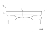
- FIG. 2 shows a side view of a payment terminal 200 according to a second embodiment.
- the card reading unit 26 is formed as Einstecknoseleseiki, in which the magnetic strip and / or chip card 28 can be inserted.
- no printer 16 is provided.
- a mobile printer 16 can also be used in this embodiment.
- FIG. 4 shows a side view of a payment terminal 300 according to a third embodiment.
- the docking station 14 includes an accumulator receiving area in which a peerakkumulator 42 can be accommodated.
- This can be used instead of the original battery of the tablet PC 12 in the tablet PC 12, so that the tablet PC 12 without having to be recharged to continue to operate.
- the accumulator receiving area 40 is designed such that the exchange accumulator 42 arranged in it can be charged via the docking station 14.
- the arrangement of thedevakkumulators 42 in an arranged within the docking station 14 accumulator receiving portion 42 a very compact construction is also achieved.
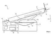
- FIG. 5 1 is a schematic illustration of a payment terminal 500 according to a fifth embodiment.
- the charging of the tablet PC 12 takes place via the back of the payment terminal.
- FIG. 6 is a schematic simplified side view of a payment terminal 600 according to a sixth embodiment, shown in FIG. 6 in a first end position, in which the display area of the touch screen 24 faces a cash point, and in FIG. 7 a second end position is shown, in which the display area is facing a customer.
- the tablet PC 12 comprises a first card reading unit 26 designed as a pull-through card reading unit and a second card reading unit 50 designed as a plug-in card reading unit, into which a chip card can be inserted.
- the pull-through card reading unit can be swung out and / or lowered, so that it can be pivoted into and out of the housing.
- only one of the two card reading units 26, 50 can be provided.
- the card reading unit 26 can also be designed as a plug-in card reading unit.
- the tablet PC 12 in this sixth embodiment two accumulators, wherein the standard provided accumulator with the reference numeral 52 and an additional, in particular at the back of the tablet PC 12 flangeable, accumulator is designated by the reference 54.
- the tablet PC 12 is arranged tiltable about the pivot axis 56 relative to the docking station 14, so that it in the direction of the double arrow P1 about this pivot axis 56 between the in FIG. 6 and FIG. 7 shown end positions can be tilted so that the operation can be done by both the cash and by the customer in an ergonomic manner. It is especially advantageous if In each of the two end positions latching functions are provided so that the tablet PC 12 engages in these end positions and thus it can be pivoted only by overcoming a predetermined force in the direction of the other end position. This ensures easy operation of the touch screen 24 and avoids unwanted pivoting.
- the printer receiving area 30 is configured such that an electrical connection is formed between the printer 16 and the docking station 14 when the printer 16 is received in the printer receiving area 30 so that the accumulator 58 of the printer 16 can be charged.
- the tablet PC 12 may also be mounted on a turntable of the docking station 14, so that the optional orientation of the tablet PC 12 to the customer or the cash on turning the tablet PC 12 using this swivel relative to the footprint of Docking station 14 can be done.
Landscapes
- Physics & Mathematics (AREA)
- General Physics & Mathematics (AREA)
- Cash Registers Or Receiving Machines (AREA)
Abstract
Description
- Die Erfindung betrifft ein Bezahlterminal zum bargeldlosen Bezahlen.
- Bezahlterminals zum bargeldlosen Bezahlen werden insbesondere in Einzelhandelsfilialen oder Gastronomiebetrieben verwendet. Während die Bezahlterminals in Gastronomiebetrieben häufig tragbar sind, sind die Bezahlterminals an den Kassenplätzen von Einzelhandelsfilialen in der Regel ortsfest angebracht.
- Bekannte Bezahlterminals weisen in der Regel einen Kartenleser zum Lesen einer Magnetstreifen- und/oder Chipkarte, beispielsweise einer EC-Karte, eine Tastatur zur Eingabe der PIN, eine Anzeige und einen integrierten Drucker zum Ausdrucken von Belegen auf. Die einzelnen Komponenten sind als eine einzige Vorrichtung innerhalb eines gemeinsamen Gehäuses angeordnet. Die ortsfesten Bezahlterminals von Kassenplätzen sind über Kabel mit weiteren Geräten des Kassenarbeitsplatzes zur Stromversorgung und zur Datenübertragung verbunden. Damit die ortsfesten Bezahlterminals sowohl von dem Kassenpersonal als auch von den Kunden bedient werden können, sind diese um einer vertikal verlaufenden Drehachse drehbar gelagert. Neben den Bezahlterminal können an dem Kassenarbeitsplatz noch weitere Geräte wie zum Beispiel ein Monitor, eine Tastatur, ein Computer, ein Warenscanner, eine Kassenlade und/oder eine Kundenanzeige zur Anzeige von Informationen an den Kunden vorhanden sein. Diese einzelnen Geräte sind miteinander zur Datenübertragung und Stromversorgung über entsprechende Kabel verkabelt und weisen einen hohen Platzbedarf auf.
- Problematisch an den bekannten Bezahlterminals ist es, dass diese durch ihren festen Aufbau jeweils nur für den vorgesehen Verwendungszweck genutzt werden können. Ein flexibles Anpassen eines Bezahlterminals an die jeweiligen Kundenbedürfnisse ist mit großem Aufwand verbunden.
- Aus dem Dokument
WO 02/09054 A2 WO 2011/148168 A2 offenbart ein Bezahlterminal, bei dem der Kartenleser in das Gehäuse eines Tablet-PCs integriert ist. - Es ist Aufgabe der Erfindung, ein universell einsetzbares einfach aufgebautes Bezahlterminal anzugeben.
- Diese Aufgabe wird durch ein Bezahlterminal mit den Merkmalen des Anspruchs 1 gelöst. Vorteilhafte Weiterbildungen der Erfindung sind in den abhängigen Ansprüchen angegeben.
- Erfindungsgemäß umfasst das Bezahlterminal einen Tablet-PC und eine Dockingstation zum Halten dieses Tablet-PCs. Der Tablet-PC ist hierbei über eine lös-und wiederherstellbare mechanische Verbindung an der Dockingstation befestigbar. Der Tablet-PC hat einen Touchscreen zur Eingabe von Informationen und zur Anzeige von Informationen an eine Bedienperson des Bezahlterminals.
- Durch das modulare Ausbilden des Bezahlterminals aus einem Tablet-PC und einer Dockingstation, die über eine lös- und wiederherstellbare Verbindung miteinander verbunden sind, wird erreicht, dass dieses Bezahlterminal sowohl als mobiles als auch als ortsfestes Bezahlterminal verwendet werden kann. Beim mobilen Verwenden kann der Tablet-PC von der Dockingstation gelöst werden und somit beispielsweise in einem Gastronomiebetrieb an den Platz des Kunden getragen werden. Bei der Verwendung des Bezahlterminals an einem Kassenarbeitsplatz dagegen ist das Bezahlterminal über die mechanische Verbindung an der Dockingstation gehalten. In beiden Fällen ermöglicht die Verwendung eines Tablet-PCs mit einem Touchscreen, dass das Bezahlterminal einfach aus Standardkomponenten zusammengesetzt werden kann und eine sehr komfortable einfache Handhabung gewährleistet ist.
- Der Tablet-PC umfasst ferner vorzugsweise mindestens einen Akkumulator zur Versorgung des Tablet-PCs mit elektrischer Energie. Zwischen der Dockingstation und dem Tablet-PC ist, wenn der Tablet-PC über die mechanische Verbindung an der Dockingstation befestigt ist, eine elektrische Verbindung zum Wiederaufladen des Akkumulators ausgebildet. Somit wird erreicht, dass der Tablet-PC bei seiner Aufnahme in der Dockingstation, also während des ortsfesten Betriebes des Bezahlterminals auf einfache Weise geladen werden kann. Ferner ermöglicht der Akkumulator, dass der Tablet-PC beim mobilen Bezahlen, also wenn er von der Dockingstation gelöst ist, trotzdem mit elektrischer Energie versorgt wird.
- Die lös- und wiederherstellbare mechanische Verbindung ist insbesondere als Rast- und/oder Steckverbindung ausgebildet, wozu der Tablet-PC insbesondere ein erstes Rastelement und die Dockingstation ein komplementär hierzu ausgebildetes zweites Rastelement umfasst, die zum Herstellen einer mechanischen Verbindung ineinander einrasten. Somit kann der Tablet-PC auch von einem technischen Laien ohne Werkzeug aneinander befestigt und wieder voneinander gelöst werden.
- Die mechanische Verbindung ist insbesondere derart ausgebildet, dass ein über die mechanische Verbindung an der Dockingstation befestigter Tablet-PC um eine Schwenkachse verschwenkbar ist, so dass ein Anzeigebereich des Touchscreens je nach Verschwenken des Tablet-PCs wahlweise einer Kassenkraft oder einem Kunden zuwendbar ist. Somit ist über nur einen Anzeigebereich, also nur einen Touchscreen, die Eingabe sowohl über die Kassenkraft als auch über einen Kunden möglich. Damit ist ein einfacher, kostengünstiger Aufbau erreicht.
- Die mechanische Verbindung ist insbesondere als ein Wippenlager ausgebildet, durch das der Tablet-PC relativ zur Dockingstation ähnlich einer Wippe um die Schwenkachse gekippt werden kann. Ein solches Verschwenken bzw. Kippen hat gegenüber dem bekannten Drehen den Vorteil, dass die Bewegung nur um einen wesentlich kleineren Winkel erfolgen muss und ein entsprechendes Wippenlager wesentlich einfacher ausgebildet sein kann.
- Der Tablet-PC ist insbesondere um einen Winkel im Bereich zwischen 30° und 90° verschwenkbar, so dass der Anzeigebereich sowohl von dem Kunden als auch der Kassenkraft in ergonomisch vorteilhafter Weise betrachtet werden kann. Die Schwenkachse ist bei der betriebsplanmäßigen Anordnung der Dockingstation, also bei der Anordnung, in der die Dockingstation beim planmäßigen Betrieb angeordnet ist, horizontal angeordnet.
- Ferner ist es vorteilhaft, wenn der Tablet-PC einen ersten elektrischen Kontakt und die Dockingstation einen komplementär zu diesem ersten elektrischen Kontakt ausgebildeten zweiten elektrischen Kontakt umfasst, wobei beim Herstellen der mechanischen Verbindung automatisch eine Kontaktierung zwischen dem ersten und dem zweiten elektrischen Kontakt erfolgt, so dass die elektrische Verbindung zwischen der Dockingstation und dem Tablet-PC ausgebildet ist. Somit wird erreicht, dass beim Befestigen des Tablet-PCs an der Dockingstation automatisch die zum Aufladen des Akkumulators des Tablet-PCs notwendige elektrische Verbindung hergestellt wird und sichergestellt wird, dass der Tablet-PC geladen wird.
- Der Tablet-PC hat insbesondere mindestens eine Kartenleseeinheit zum Lesen einer Magnetstreifen- und/oder Chipkarte. Es ist besonders vorteilhaft, wenn der Tablet-PC zwei Kartenleseeinheiten umfasst, wobei die erste dieser beiden Kartenleseeinheiten als Einsteckkartenleseeinheit zum Einstecken einer zu lesenden Chipkarte und die zweite der beiden Kartenleseeinheiten als Durchzugskartenleseeinheit zum Durchziehen einer zu lesenden Magnetstreifenkarte ausgebildet ist. Die Kartenleseeinheit bzw. die beiden Kartenleseeinheiten sind insbesondere in dem Gehäuse des Tablet-PCs angeordnet, so dass ein einfacher platzsparender Aufbau ausgebildet ist. Die Kartenleseeinheiten können beispielsweise auch klappbar und/oder versenkbar angeordnet sein, so dass der Platzbedarf weiter reduziert wird.
- Ferner ist vorteilhaft, wenn das Bezahlterminal einen mobilen Drucker zum Drucken von Kassenbons umfasst, wobei dieser Drucker einen Empfänger und der Tablet-PC einen Sender umfasst, so dass eine kabellose Datenübertragungsverbindung zwischen dem Tablet-PC und dem Drucker ausgebildet werden kann. Somit ist keine physische Verbindung zwischen dem Tablet-PC und dem Drucker, insbesondere keine Verkabelung notwendig. Bei dieser kabellosen Datenübertragungsverbindung handelt es sich insbesondere um eine Bluetooth-Verbindung.
- Ferner ist es vorteilhaft, wenn die Dockingstation einen Aufnahmebereich zur Aufnahme mindestens eines Teils des Druckers umfasst. Zwischen der Dockingstation und dem Drucker ist eine elektrische Verbindung zum Aufladen eines Akkumulators des Druckers ausgebildet, wenn der Drucker in diesem Aufnahmebereich aufgenommen ist. Somit wird erreicht, dass der Drucker zum einen mobil ist und somit ortsfern von der Dockingstation angeordnet werden kann, je nachdem wie es der Arbeitsplatz erfordert, aber zum anderen das Aufladen des Akkumulators des mobilen Druckers auf einfache Weise über die Dockingstation erfolgen kann. Insbesondere muss somit der Drucker nicht über ein Kabel an das Stromnetz angeschlossen werden.
- Der Tablet-PC hat an der dem Anzeigebereich gegenüberliegenden Seite, also seiner Rückseite, insbesondere ein Befestigungselement zum Anbringen eines weiteren Akkumulators zur Versorgung des Tablet-PCs mit elektrischer Energie. Somit wird erreicht, dass die Betriebszeit des Tablet-PCs, ohne dass dieses aufgeladen werden muss, erhöht wird. Dieser zusätzliche Akkumulator ist insbesondere an einem Handgriff befestigbar. Das Befestigungselement, an dem der weitere Akkumulator an dem Tablet-PC befestigbar ist, ist insbesondere derart ausgebildet, dass der Akkumulator über eine lös- und wiederherstellbare Verbindung an dem Tablet-PC befestigbar, insbesondere anflanschbar, ist.
- Darüber hinaus ist es vorteilhaft, wenn die Dockingstation einen Akkumulatoraufnahmebereich aufweist, in dem ein weitere Austauschakkumulator für den Tablet-PC aufgenommen werden kann, wobei dieser Akkumulatoraufnahmebereich derart ausgebildet ist, dass ein in ihm aufgenommener Austauschakkumulator über die Dockingstation ebenfalls geladen werden kann. Dies ermöglicht, dass, sofern der bzw. die Akkumulatoren des Tablet-PCs entladen sind, dieser durch Verwendung des Austauschakkumulators weiterbetrieben werden kann, ohne dass der Tablet-PC an der Dockingstation zum Aufladen befestigt werden muss. Das Vorsehen eines Akkumulatoraufnahmebereiches zum Aufnehmen dieses zusätzlichen Austauschakkumulators hat ferner den Vorteil, dass ein besonders platzsparender Aufbau erreicht ist.
- Die lös- und wiederherstellbare Verbindung, über die der Tablet-PC an der Dockingstation befestigbar ist, ist insbesondere über ein Verriegelungselement mechanisch verriegelbar, so dass der Tablet-PC nicht einfach von einer unbefugten Person entrissen werden kann.
- Der Tablet-PC weist insbesondere ein Speicherelement, eine Kamera, einen Barcode-Reader, einen Lautsprecher, einen Lagesensor und/oder eine Sende- und/oder Empfangseinheit zum Senden oder Empfangen von Daten, beispielsweise Bluetooth, Wi-Fi, NFC und/oder RFID, auf. Somit kann der Tablet-PC nicht nur für das Bezahlterminal, sondern auch zum Ersetzen weiterer Geräte des Kassenarbeitsplatzes verwendet werden. Somit ist es durch den Tablet-PC nicht mehr notwendig, einen Monitor, eine Tastatur, einen PC und/oder einen Warenscanner zusätzlich vorzusehen, so dass der Kassenarbeitsplatz wesentlich einfacher und platzsparender ausgebildet sein kann.
- Zusätzlich oder alternativ können auch an der Dockingstation ein Warenscanner, eine Kassenlade, ein Drucker, eine Kundenanzeige und/oder eine Anzeige für das Kassenpersonal vorgesehen sein.
- Ferner ist es vorteilhaft, wenn das Wippenlager derart ausgebildet ist, dass der Tablet-PC in vorbestimmten Endlagen einrastet, wobei er in einer dieser Endlagen dem Kunden und in der anderen Endlage dem Kassenpersonal zugeordnet ist. Über dieses Einrasten wird ein sicheres Halten des Tablet-PCs auch beim Bedienen, also dem "Touchen" des Touchscreens, sichergestellt.
- Die Steck- und/oder Rastelemente sind insbesondere derart ausgebildet, dass an der Dockingstation unterschiedlich große Tablet-PCs befestigt werden können, beispielsweise Tablet-PCs mit sieben Zoll und zehn Zoll Durchmesser.
- Bei einer alternativen Ausführungsform der Erfindung kann auch zwischen der Dockingstation und dem Tablet-PC eine drahtlose Datenübertragungsverbindung, beispielsweise eine Bluetooth-Verbindung, ausgebildet sein. In diesem Fall ist der Drucker insbesondere über eine kabelgebundene oder kabellose Datenübertragungsverbindung mit der Dockingstation verbunden und erhält die Druckaufträge des Tablet-PCs über die Dockingstation.
- Weitere Merkmale und Vorteile der Erfindung ergeben sich aus der folgenden Beschreibung, die die Erfindung anhand von Ausführungsbeispielen im Zusammenhang mit den beigefügten Figuren näher erläutert.
- Es zeigen:
- Fig.1
- eine schematische, perspektivische Darstellung eines Bezahlterminals gemäß einer ersten Ausführungsform im zusammengesteckten Zustand;
- Fig.2
- eine schematische, perspektivische Darstellung des Bezahlterminals nach
Fig.1 in einem auseinandergenommenen Zustand; - Fig.3
- eine Seitenansicht eines Bezahlterminals gemäß einer zweiten Ausführungsform;
- Fig.4
- eine Seitenansicht eines Bezahlterminals gemäß einer dritten Ausführungsform;
- Fig.5
- eine Seitenansicht eines Bezahlterminals gemäß einer vierten Ausführungsform;
- Fig.6
- eine Seitenansicht eines Bezahlterminals gemäß einer fünften Ausführungsform in einer ersten Endposition; und
- Fig.7
- eine Seitenansicht des Bezahlterminals nach
Fig.6 in einer zweiten Endposition. - In
Fig.1 ist eine schematische, perspektivische Darstellung eines Bezahlterminals 100 gemäß einer ersten Ausführungsform im zusammengesteckten Zustand dargestellt.Fig.2 zeigt eine schematische, perspektivische Darstellung dieses Bezahlterminals 100 im auseinandergenommenen Zustand, so dass die einzelnen einfach zusammensteckbaren Komponenten des Bezahlterminals 100 gut sichtbar sind. - Das Bezahlterminal 100 umfasst einen Tablet-PC 12 und eine Dockingstation 14, an der der Tablet-PC 12 zum Halten über eine lös- und wiederherstellbare mechanische Verbindung befestigbar ist. Ferner hat das Bezahlterminal 100 einen mobilen Drucker 16 zum Drucken von Belegen 18.
- Der Tablet-PC weist zwei erste Rastelemente auf, von denen eines mit dem Bezugszeichen 20 bezeichnet ist. Die Dockingstation 14 hat zwei komplementär zu den ersten Rastelementen ausgebildete zweite Rastelemente 22, wobei die ersten und die zweiten Rastelemente 20, 22 zum Herstellen der lös-und wiederherstellbaren Verbindung ineinander einrasten. Die zweiten Rastelemente 22 sind insbesondere als Erhebungen und die ersten Rastelemente 20 als entsprechend komplementäre Aussparungen vorgesehen, so dass ein einfaches Einrasten zum Verbinden des Tablet-PCs 12 in der Dockingstation 14 möglich ist und der Tablet-PC 12 relativ zur Dockingstation kippbar ist. Diese Rastverbindung ist insbesondere derart ausgebildet, dass durch sie ein Wippenlager ausgebildet ist, so dass der Tablet-PC 12 um eine Schwenkachse relativ zur Dockingstation 14 verschwenkbar ist, wenn er an der Dockingstation 14 befestigt ist. Diese Schwenkachse wird insbesondere durch die Verbindung der Mittelpunkte der Kontaktbereiche zwischen den ersten und den zweiten Rastelementen 20, 22 definiert und ist bei der planmäßigen Ausrichtung des Bezahlterminals 100, wie dieses im Betrieb verwendet wird, horizontal gerichtet. Über dieses Wippenlager wird ermöglicht, dass der Tablet-PC 12 relativ zur Dockingstation 14 gekippt werden kann, so dass er, wie später noch im Zusammenhang mit den
Fig.5 und6 näher erläutert, wahlweise einer Kassenkraft und einem Kunden zugewandt werden kann. - Der Tablet-PC 12 weist einen Touchscreen 24 auf, über den Informationen angezeigt werden können. Insbesondere kann über den Touchscreen 24 eine virtuelle Tastatur angezeigt werden, über die der Kunde beim bargeldlosen Bezahlen die PIN-Nummer eingeben kann. Der Tablet-PC 12 hat ferner mindestens eine Kartenleseeinheit 26 zum Lesen einer Magnetstreifen- und/oder Chipkarte 28. Bei dieser Magnetstreifen- und/oder Chipkarte 28 handelt es sich beispielsweise um eine EC-Karte oder Kreditkarte, mit der der Kunde bargeldlos bezahlen kann. Die Kartenleseeinheit 26 ist insbesondere in das Gehäuse des Tablet-PCs 12 integriert und/oder versenk- und/oder schwenkbar an diesem angeordnet. Es ist insbesondere vorteilhaft, wenn zwei Kartenleseeinheiten 26 vorgesehen sind, wobei eine dieser Kartenleseeinheiten als Einsteckkartenleseeinheit und die andere als Durchzugskartenleseeinheit ausgebildet ist.
- Bei dem in den
Fig.1 und2 gezeigten Ausführungsbeispiel ist die Kartenleseeinheit 26 an der Kopfseite des Tablet-PCs angeordnet. Alternativ kann die Kartenleseeinheit aber auch an der Seite des Tablet-PCs 12 angeordnet sein. - Die Dockingstation 14 dient neben dem Halten insbesondere auch zum Aufladen eines Akkumulators des Tablet-PCs 12. Hierzu umfasst der Tablet-PC 12 insbesondere mindestens einen ersten elektrischen Kontakt und die Dockingstation 14 mindestens einen komplementär hierzu ausgebildeten zweiten elektrischen Kontakt, wobei diese elektrischen Kontakte vorzugsweise an den Elementen 20, 22 angeordnet sind, so dass diese sich, wenn der Tablet-PC an der Dockingstation 14 über die Rastverbindung gehalten ist, automatisch in Kontakt miteinander befinden und somit eine elektrische Verbindung zum Aufladen des Tablet-PCs 12 ausgebildet ist.
- Ferner hat die Dockingstation 14 einen Druckeraufnahmebereich 30, in den der mobile Drucker 16 zumindest teilweise aufnehmbar ist, wie dies in
Fig.1 gezeigt ist. Dieser Aufnahmebereich 30 ist insbesondere derart ausgebildet, dass zwischen dem Drucker 16 und der Dockingstation 14 ebenfalls eine elektrische Verbindung ausgebildet ist, wenn der Drucker 16 in dem Druckeraufnahmebereich 30 aufgenommen ist, so dass auch ein Akkumulator des Druckers 16 über die Dockingstation 14 aufgeladen werden kann. - Der Drucker 16 umfasst ferner insbesondere einen, nicht gezeigten, Empfänger zum drahtlosen Empfangen von Daten. Der Tablet-PC 12 hat insbesondere einen Sender zum drahtlosen Senden von Daten, so dass über eine zwischen dem Sender des Tablet-PCs 12 und dem Empfänger des Druckers 16 ausgebildete drahtlose Datenübertragungsverbindung, insbesondere eine Bluetooth-Verbindung, auf einfache Weise Daten eines Druckauftrages zum Drucken eines Beleges 18 übertragen werden können. Somit kann auf eine Verkabelung zwischen den Modulen 12, 14, 16 des Bezahlterminals 100 verzichtet werden. Die einzelnen Module 12, 14, 16 können somit auf einfache Weise ohne Werkzeuge von einem technischen Laien miteinander verbunden und voneinander getrennt werden, so dass die Anordnung an die individuellen Bedürfnisse angepasst werden kann. Insbesondere kann der Tablet-PC 12 jederzeit problemlos von der Dockingstation 14 gelöst werden, so dass er zum mobilen Bezahlen an einem anderen Ort, beispielsweise den Tisch eines Kunden, verbracht werden kann.
- In
Fig.3 ist eine Seitenansicht eines Bezahlterminals 200 gemäß einer zweiten Ausführungsform gezeigt. Bei dieser zweiten Ausführungsform ist die Kartenleseeinheit 26 als Einsteckkartenleseeinheit ausgebildet, in die die Magnetstreifen und/oder Chipkarte 28 eingesteckt werden kann. Bei dieser zweiten Ausführungsform ist kein Drucker 16 vorgesehen. Alternativ kann aber auch bei dieser Ausführungsform ein mobiler Drucker 16 verwendet werden. -
Figur 4 zeigt eine Seitenansicht eines Bezahlterminals 300 gemäß einer dritten Ausführungsform. Bei dieser dritten Ausführungsform umfasst die Dockingstation 14 einen Akkumulatoraufnahmebereich, in dem ein Austauschakkumulator 42 aufgenommen werden kann. Dieser Austauschakkumulator 42 kann anstelle des ursprünglichen Akkumulators des Tablet-PCs 12 in den Tablet-PC 12 eingesetzt werden, so dass der Tablet-PC 12 ohne wieder aufgeladen werden zu müssen weiter betrieben werden kann. Der Akkumulatoraufnahmebereich 40 ist derart ausgebildet, dass der in ihm angeordnete Austauschakkumulator 42 über die Dockingstation 14 geladen werden kann. Durch die Anordnung des Austauschakkumulators 42 in einem innerhalb der Dockingstation 14 angeordneten Akkumulatoraufnahmebereich 42 wird ferner ein sehr kompakter Aufbau erreicht. - In
Figur 5 ist eine schematische Darstellung eines Bezahlterminals 500 gemäß einer fünften Ausführungsform gezeigt. Bei dieser fünften Ausführungsform erfolgt das Aufladen des Tablet-PCs 12 über die Rückseite des Bezahlterminals. - In
Figur 6 ist eine schematische stark vereinfachte Seitenansicht eines Bezahlterminals 600 gemäß einer sechsten Ausführungsform gezeigt, wobei inFigur 6 in eine erste Endposition, in der der Anzeigebereich des Touchscreens 24 einer Kassenkraft zugewandt ist, und inFigur 7 eine zweite Endposition gezeigt ist, in der der Anzeigebereich einem Kunden zugewandt ist. - Bei dieser sechsten Ausführungsform umfasst der Tablet-PC 12 eine als Durchzugskartenleseeinheit ausgebildete erste Kartenleseeinheit 26 und eine als Einsteckkartenleseeinheit ausgebildete zweite Kartenleseeinheit 50, in die eine Chipkarte eingesteckt werden kann. Die Durchzugskartenleseeinheit ist insbesondere ausschwenkbar und/oder versenkbar angeordnet, so dass sie in das Gehäuse hinein und aus dem Gehäuse heraus verschwenkt werden kann. Alternativ kann nur eine der beiden Kartenleseeinheiten 26, 50 vorgesehen sein. Ferner kann die Kartenleseeinheit 26 auch ebenfalls als Einsteckkartenleseeinheit ausgebildet sein.
- Ferner hat der Tablet-PC 12 bei dieser sechsten Ausführungsform zwei Akkumulatoren, wobei der standardmäßig vorgesehene Akkumulator mit dem Bezugszeichen 52 und ein zusätzlicher, insbesondere an der Rückseite der Tablet-PC 12 anflanschbarer, Akkumulator mit dem Bezugszeichneten 54 bezeichnet ist.
- Der Tablet-PC 12 ist um die Schwenkachse 56 relativ zur Dockingstation 14 kippbar angeordnet, so dass er in Richtung des Doppelpfeiles P1 um diese Schwenkachse 56 zwischen den in
Figur 6 undFigur 7 gezeigten Endpositionen verkippt werden kann, damit die Bedienung sowohl durch die Kassenkraft als auch durch den Kunden in ergonomisch vorteilhafter Weise erfolgen kann. Es ist besonders vorteilhaft, wenn in den beiden Endlagen jeweils Rastfunktionen vorgesehen sind, so dass der Tablet-PC 12 in diesen Endlagen einrastet und er somit nur bei Überwindung einer vorbestimmten Kraft in Richtung der anderen Endlage verschwenkt werden kann. Dadurch wird eine einfache Bedienung des Touchscreens 24 sichergestellt und ein ungewolltes Verschwenken vermieden. - Der Druckeraufnahmebereich 30 ist derart ausgebildet, dass zwischen dem Drucker 16 und der Dockingstation 14 eine elektrische Verbindung ausgebildet ist, wenn der Drucker 16 in dem Druckeraufnahmebereich 30 aufgenommen ist, so dass der Akkumulator 58 des Druckers 16 aufgeladen werden kann.
- Anstelle eines Wippenlagers kann der Tablet-PC 12 auch an einer Drehscheibe der Dockingstation 14 gelagert sein, so dass die wahlweise Ausrichtung des Tablet-PCs 12 zum Kunden oder der Kassenkraft über ein Drehen des Tablet-PCs 12 mit Hilfe dieses Drehfußes relativ zur Standfläche der Dockingstation 14 erfolgen kann.
-
- 100, 200, 300, 400, 500, 600
- Bezahlterminal
- 12
- Tablet-PC
- 14
- Dockingstation
- 16
- Drucker
- 18
- Beleg
- 20, 22
- Rastelement
- 24
- Touchscreen
- 26, 50
- Kartenleseeinheit
- 28
- Magnetstreifen- und/oder Chipkarte
- 30
- Druckeraufnahmebereich
- 40
- Akkumulatoraufnahmebereich
- 42, 52, 54
- Akkumulator
- 56
- Drehachse
- 58
- Akkumulator
- P1
- Richtung
Claims (15)
- Bezahlterminal,
umfassend einen Tablet-PC (12) und eine Dockingstation (14) zum Halten des Tablet-PCs (12),
wobei der Tablet-PC (12) über eine lös- und wiederherstellbare mechanische Verbindung an der Dockingstation (14)befestigbar ist, und
wobei der Tablet-PC (12) einen Touchscreen (24) zur Eingabe von Informationen und zur Anzeige von Informationen an eine Bedienperson des Bezahlterminals (100 bis 600) umfasst. - Bezahlterminal (100 bis 600) nach Anspruch 1, dadurch gekennzeichnet, dass der Tablet-PC (12) mindestens einen Akkumulator (52) zur Versorgung mit elektrischer Energie umfasst, und dass zwischen der Dockingstation (14) und dem Tablet-PC (12), wenn dieser über die mechanische Verbindung an der Dockingstation (14) befestigt ist, eine elektrische Verbindung zum Aufladen des Akkumulators (50) ausgebildet ist.
- Bezahlterminal (100 bis 600) nach Anspruch 1 oder 2, dadurch gekennzeichnet, dass die mechanische Verbindung als Rast- und/oder Steckverbindung ausgebildet ist.
- Bezahlterminal (100 bis 600) nach einem der vorhergehenden Ansprüche, dadurch gekennzeichnet, dass die mechanische Verbindung derart ausgebildet ist, dass der über diese mechanische Verbindung an der Dockingstation (14) befestigte Tablet-PC um eine Schwenkachse (56) verschwenkbar ist, so dass der Anzeigebereich des Touchscreens (24) wahlweise einer Kassenkraft oder einem Kunden zuwendbar ist.
- Bezahlterminal (100 bis 600) nach Anspruch 4, dadurch gekennzeichnet, dass die mechanische Verbindung als Wippenlager ausgebildet ist.
- Bezahlterminal (100 bis 600) nach Anspruch 4 oder 5, dadurch gekennzeichnet, dass der Tablet-PC (12) um einen Winkel im Bereich zwischen 30° und 90° verschwenkbar ist.
- Bezahlterminal (100 bis 600) nach einem der Ansprüche 3 bis 6, dadurch gekennzeichnet, dass die Schwenkachse (56) bei der betriebsplanmäßigen Anordnung der Dockingstation (14) horizontal verläuft.
- Bezahlterminal (100 bis 600) nach einem der vorhergehenden Ansprüche, dadurch gekennzeichnet, dass der Tablet-PC (12) einen ersten elektrischen Kontakt und die Dockingstation einen komplementär zum ersten elektrischen Kontakt ausgebildeten zweiten elektrischen Kontakt aufweist, und dass beim Herstellen der mechanischen Verbindung automatsch ein Kontakt zwischen dem ersten und dem zweiten elektrischen Kontakt ausgebildet wird, so dass die elektrische Verbindung zwischen der Dockingstation (14) und dem Tablet-PC (12) ausgebildet ist.
- Bezahlterminal (100 bis 600) nach einem der vorhergehenden Ansprüche, dadurch gekennzeichnet, dass der Tablet-PC (12) eine Kartenleseeinheit (26, 50) zum Lesen einer Magnetstreifen- und/oder Chipkarten (28) umfasst.
- Bezahlterminal (100 bis 600) nach einem der Ansprüche 1 bis 8, dadurch gekennzeichnet, dass der Tablet-PC (12) eine erste Einsteckkartenleseeinheit (26, 50) zum Einstecken einer zu lesenden Chipkarten (28) und eine zweite Durchzugskartenleseeinheit (26, 50) zum Durchziehen einer zu lesenden Magnetstreifenkarte (28) umfasst.
- Bezahlterminal (100 bis 600) nach einem der vorhergehenden Ansprüche, dadurch gekennzeichnet, dass ein mobiler Drucker (16) zum Drucken von Belegen (18) vorgesehen ist, und dass der Drucker (16) einen Empfänger und der Tablet-PC (12) einen Sender umfasst, so dass eine kabellose Datenübertragungsverbindung, insbesondere eine Bluetooth-Verbindung, zwischen dem Tablet-PC (12) und dem Drucker (16) zum Übertagen von Daten herstellbar ist.
- Bezahlterminal (100 bis 600) nach Anspruch 11, dadurch gekennzeichnet, dass die Dockingstation (14) einen Aufnahmebereich (30) zur zumindest teilweisen Aufnahme des Druckers (16) umfasst, und dass zwischen der Dockingstation (14) und dem Drucker (16) eine elektrische Verbindung zum Aufladen eines Akkumulator (58) des Druckers (16) ausgebildet ist, wenn der Drucker (16) in dem Aufnahmebereich (30) aufgenommen ist.
- Bezahlterminal (100 bis 600) nach einem der vorhergehenden Ansprüche, dadurch gekennzeichnet, der Tablet-PC (12) an der dem Anzeigebereich gegenüberliegenden Seiten ein Befestigungselement zum Anbringen eines weiteren Akkumulators (54) zur Versorgung des Tablet-PCs (12) mit elektrischer Energie umfasst.
- Bezahlterminal (100 bis 600) nach Anspruch 13, dadurch gekennzeichnet, dass an dem Befestigungselement der weitere Akkumulator (54) über eine lös- und wiederherstellbare Verbindung befestigt, insbesondere angeflanscht, ist.
- Bezahlterminal (100 bis 600) nach einem der vorhergehenden Ansprüche, dadurch gekennzeichnet, dass die Dockingstation (14) einen Akkumulatoraufnahmebereich (40) zum Aufladen eines Austauschakkumulators (42) für den Tablet-PC (12) umfasst.
Priority Applications (1)
| Application Number | Priority Date | Filing Date | Title |
|---|---|---|---|
| EP12174750.5A EP2682921B1 (de) | 2012-07-03 | 2012-07-03 | Bezahlterminal |
Applications Claiming Priority (1)
| Application Number | Priority Date | Filing Date | Title |
|---|---|---|---|
| EP12174750.5A EP2682921B1 (de) | 2012-07-03 | 2012-07-03 | Bezahlterminal |
Publications (2)
| Publication Number | Publication Date |
|---|---|
| EP2682921A1 true EP2682921A1 (de) | 2014-01-08 |
| EP2682921B1 EP2682921B1 (de) | 2021-06-02 |
Family
ID=46516550
Family Applications (1)
| Application Number | Title | Priority Date | Filing Date |
|---|---|---|---|
| EP12174750.5A Active EP2682921B1 (de) | 2012-07-03 | 2012-07-03 | Bezahlterminal |
Country Status (1)
| Country | Link |
|---|---|
| EP (1) | EP2682921B1 (de) |
Cited By (4)
| Publication number | Priority date | Publication date | Assignee | Title |
|---|---|---|---|---|
| DE102013103990A1 (de) * | 2013-04-19 | 2014-11-06 | PCP GmbH | System mit Bezahleinrichtung und mobiler Andockstation |
| DE202016003776U1 (de) | 2016-06-17 | 2016-08-11 | Collatz+Trojan Gmbh | Bedienterminal |
| CN107093296A (zh) * | 2017-05-10 | 2017-08-25 | 浙江深大智能科技有限公司 | 一种用于显示单元的安装结构及支付终端设备 |
| JP2021026533A (ja) * | 2019-08-06 | 2021-02-22 | カシオ計算機株式会社 | 載置台および電子機器 |
Citations (6)
| Publication number | Priority date | Publication date | Assignee | Title |
|---|---|---|---|---|
| US5237487A (en) * | 1992-03-02 | 1993-08-17 | Ncr Corporation | Transaction terminal having base module and portable module |
| US5640002A (en) * | 1995-08-15 | 1997-06-17 | Ruppert; Jonathan Paul | Portable RF ID tag and barcode reader |
| WO2002009054A2 (en) | 2000-07-25 | 2002-01-31 | Khyber Technologies Corporation | Wearable point-of-sale device having a detachable handheld unit and a printing holster |
| US20050213298A1 (en) * | 2002-06-19 | 2005-09-29 | Motion Computing, Inc. | Docking support for a tablet computer with extended battery |
| WO2011148168A2 (en) | 2010-05-24 | 2011-12-01 | Secure Electrans Limited | Electronic payment unit, electronic payment origin authentication system and method |
| WO2012123573A1 (de) * | 2011-03-16 | 2012-09-20 | Wincor Nixdorf International Gmbh | Belegdrucker zum bedrucken von belegen |
Family Cites Families (3)
| Publication number | Priority date | Publication date | Assignee | Title |
|---|---|---|---|---|
| JPH1139125A (ja) * | 1997-07-24 | 1999-02-12 | Matsushita Electric Ind Co Ltd | 接客用端末の表示装置 |
| BR0301164A (pt) * | 2003-05-19 | 2005-05-10 | Sp Itaqui Participacoees Ltda | Terminal multifuncional para transações comerciais |
| JP2010244429A (ja) * | 2009-04-08 | 2010-10-28 | Toshiba Tec Corp | Posターミナル |
-
2012
- 2012-07-03 EP EP12174750.5A patent/EP2682921B1/de active Active
Patent Citations (6)
| Publication number | Priority date | Publication date | Assignee | Title |
|---|---|---|---|---|
| US5237487A (en) * | 1992-03-02 | 1993-08-17 | Ncr Corporation | Transaction terminal having base module and portable module |
| US5640002A (en) * | 1995-08-15 | 1997-06-17 | Ruppert; Jonathan Paul | Portable RF ID tag and barcode reader |
| WO2002009054A2 (en) | 2000-07-25 | 2002-01-31 | Khyber Technologies Corporation | Wearable point-of-sale device having a detachable handheld unit and a printing holster |
| US20050213298A1 (en) * | 2002-06-19 | 2005-09-29 | Motion Computing, Inc. | Docking support for a tablet computer with extended battery |
| WO2011148168A2 (en) | 2010-05-24 | 2011-12-01 | Secure Electrans Limited | Electronic payment unit, electronic payment origin authentication system and method |
| WO2012123573A1 (de) * | 2011-03-16 | 2012-09-20 | Wincor Nixdorf International Gmbh | Belegdrucker zum bedrucken von belegen |
Cited By (5)
| Publication number | Priority date | Publication date | Assignee | Title |
|---|---|---|---|---|
| DE102013103990A1 (de) * | 2013-04-19 | 2014-11-06 | PCP GmbH | System mit Bezahleinrichtung und mobiler Andockstation |
| DE202016003776U1 (de) | 2016-06-17 | 2016-08-11 | Collatz+Trojan Gmbh | Bedienterminal |
| WO2017215692A1 (de) | 2016-06-17 | 2017-12-21 | Collatz+Trojan Gmbh | Bedienterminal |
| CN107093296A (zh) * | 2017-05-10 | 2017-08-25 | 浙江深大智能科技有限公司 | 一种用于显示单元的安装结构及支付终端设备 |
| JP2021026533A (ja) * | 2019-08-06 | 2021-02-22 | カシオ計算機株式会社 | 載置台および電子機器 |
Also Published As
| Publication number | Publication date |
|---|---|
| EP2682921B1 (de) | 2021-06-02 |
Similar Documents
| Publication | Publication Date | Title |
|---|---|---|
| DE69024874T2 (de) | Tragbarer Rechner mit Faksimilemittel | |
| DE112008000910B4 (de) | Flexibles Eingangs-/Ausgangs-Verbindungssystem | |
| DE69232400T2 (de) | Elektronisches Informationsgerät | |
| DE60025442T2 (de) | Erweiterungsgerät mit einer Sicherheitsfunktion | |
| DE112013006354T5 (de) | Anzeigenbefestigungssystem | |
| EP2013681A1 (de) | Laptop-computer | |
| DE19520947A1 (de) | Tragbarer Computer mit Telekommunikationseinrichtung | |
| DE202012000065U1 (de) | Einrichtung zum Einsetzen einer elektronischen Vorrichtung in einer Zubehörvorrichtung | |
| EP2682921B1 (de) | Bezahlterminal | |
| DE112011103643T5 (de) | Endgerät | |
| DE4218179A1 (de) | Ausgabeeinrichtung, vorzugsweise für Personalcomputer | |
| EP2686749B1 (de) | Belegdrucker zum bedrucken von belegen | |
| CH711533A2 (de) | Kombination aus Computergerät und Spielesteuerung mit flexiblem Brückenabschnitt. | |
| WO2017215692A1 (de) | Bedienterminal | |
| DE3723316C1 (en) | Multi-functional checkout workstation | |
| DE102019201713A1 (de) | Ladesäule für ein Elektrofahrzeug | |
| EP2686750B1 (de) | Vorrichtung zum befestigen eines tablet-computers an einer vesa-halterung | |
| EP2463746A2 (de) | Terminalsystem zum Anbringen eines Endgerätes an einem Ständerwerk und zum elektrischen Koppeln des Endgerätes an ein Netzwerk oder eine Verarbeitungseinheit | |
| DE19854272C1 (de) | Verfahrbarer IT-Container, insbesondere als Zubehörschrank für einen Schreibtisch | |
| DE10254613B4 (de) | Kombination eines Computers mit einem Pocket-Computer | |
| DE202015101248U1 (de) | Mobile Vorrichtung zur Speicherung von elektrischer Energie und von Daten | |
| DE4223354A1 (de) | An einen handelsüblichen Computer mit Monitor-Treiberkarte anschließbares Daten-Ausgabegerät | |
| DE102017123938B4 (de) | Verfahren zum Betreiben eines Drucksystems zum Ausdrucken von Bildern und/oder Dokumenten sowie Drucksystem zum Durchführen des Verfahrens | |
| DE29607853U1 (de) | Personalcomputer mit Zusatzanschlüssen | |
| DE102013103990A1 (de) | System mit Bezahleinrichtung und mobiler Andockstation |
Legal Events
| Date | Code | Title | Description |
|---|---|---|---|
| PUAI | Public reference made under article 153(3) epc to a published international application that has entered the european phase |
Free format text: ORIGINAL CODE: 0009012 |
|
| AK | Designated contracting states |
Kind code of ref document: A1 Designated state(s): AL AT BE BG CH CY CZ DE DK EE ES FI FR GB GR HR HU IE IS IT LI LT LU LV MC MK MT NL NO PL PT RO RS SE SI SK SM TR |
|
| AX | Request for extension of the european patent |
Extension state: BA ME |
|
| 17P | Request for examination filed |
Effective date: 20140701 |
|
| RBV | Designated contracting states (corrected) |
Designated state(s): AL AT BE BG CH CY CZ DE DK EE ES FI FR GB GR HR HU IE IS IT LI LT LU LV MC MK MT NL NO PL PT RO RS SE SI SK SM TR |
|
| STAA | Information on the status of an ep patent application or granted ep patent |
Free format text: STATUS: EXAMINATION IS IN PROGRESS |
|
| 17Q | First examination report despatched |
Effective date: 20190321 |
|
| RIC1 | Information provided on ipc code assigned before grant |
Ipc: G07G 1/00 20060101AFI20200527BHEP Ipc: G07F 7/08 20060101ALI20200527BHEP |
|
| GRAP | Despatch of communication of intention to grant a patent |
Free format text: ORIGINAL CODE: EPIDOSNIGR1 |
|
| STAA | Information on the status of an ep patent application or granted ep patent |
Free format text: STATUS: GRANT OF PATENT IS INTENDED |
|
| INTG | Intention to grant announced |
Effective date: 20200723 |
|
| GRAJ | Information related to disapproval of communication of intention to grant by the applicant or resumption of examination proceedings by the epo deleted |
Free format text: ORIGINAL CODE: EPIDOSDIGR1 |
|
| STAA | Information on the status of an ep patent application or granted ep patent |
Free format text: STATUS: EXAMINATION IS IN PROGRESS |
|
| GRAS | Grant fee paid |
Free format text: ORIGINAL CODE: EPIDOSNIGR3 |
|
| STAA | Information on the status of an ep patent application or granted ep patent |
Free format text: STATUS: GRANT OF PATENT IS INTENDED |
|
| GRAP | Despatch of communication of intention to grant a patent |
Free format text: ORIGINAL CODE: EPIDOSNIGR1 |
|
| INTC | Intention to grant announced (deleted) | ||
| INTG | Intention to grant announced |
Effective date: 20201223 |
|
| GRAA | (expected) grant |
Free format text: ORIGINAL CODE: 0009210 |
|
| STAA | Information on the status of an ep patent application or granted ep patent |
Free format text: STATUS: THE PATENT HAS BEEN GRANTED |
|
| REG | Reference to a national code |
Ref country code: CH Ref legal event code: EP |
|
| AK | Designated contracting states |
Kind code of ref document: B1 Designated state(s): AL AT BE BG CH CY CZ DE DK EE ES FI FR GB GR HR HU IE IS IT LI LT LU LV MC MK MT NL NO PL PT RO RS SE SI SK SM TR |
|
| REG | Reference to a national code |
Ref country code: GB Ref legal event code: FG4D Free format text: NOT ENGLISH |
|
| REG | Reference to a national code |
Ref country code: AT Ref legal event code: REF Ref document number: 1399161 Country of ref document: AT Kind code of ref document: T Effective date: 20210615 |
|
| REG | Reference to a national code |
Ref country code: IE Ref legal event code: FG4D Free format text: LANGUAGE OF EP DOCUMENT: GERMAN |
|
| REG | Reference to a national code |
Ref country code: DE Ref legal event code: R096 Ref document number: 502012016775 Country of ref document: DE |
|
| REG | Reference to a national code |
Ref country code: LT Ref legal event code: MG9D |
|
| PG25 | Lapsed in a contracting state [announced via postgrant information from national office to epo] |
Ref country code: HR Free format text: LAPSE BECAUSE OF FAILURE TO SUBMIT A TRANSLATION OF THE DESCRIPTION OR TO PAY THE FEE WITHIN THE PRESCRIBED TIME-LIMIT Effective date: 20210602 Ref country code: BG Free format text: LAPSE BECAUSE OF FAILURE TO SUBMIT A TRANSLATION OF THE DESCRIPTION OR TO PAY THE FEE WITHIN THE PRESCRIBED TIME-LIMIT Effective date: 20210902 Ref country code: LT Free format text: LAPSE BECAUSE OF FAILURE TO SUBMIT A TRANSLATION OF THE DESCRIPTION OR TO PAY THE FEE WITHIN THE PRESCRIBED TIME-LIMIT Effective date: 20210602 Ref country code: FI Free format text: LAPSE BECAUSE OF FAILURE TO SUBMIT A TRANSLATION OF THE DESCRIPTION OR TO PAY THE FEE WITHIN THE PRESCRIBED TIME-LIMIT Effective date: 20210602 |
|
| REG | Reference to a national code |
Ref country code: NL Ref legal event code: MP Effective date: 20210602 |
|
| PG25 | Lapsed in a contracting state [announced via postgrant information from national office to epo] |
Ref country code: RS Free format text: LAPSE BECAUSE OF FAILURE TO SUBMIT A TRANSLATION OF THE DESCRIPTION OR TO PAY THE FEE WITHIN THE PRESCRIBED TIME-LIMIT Effective date: 20210602 Ref country code: SE Free format text: LAPSE BECAUSE OF FAILURE TO SUBMIT A TRANSLATION OF THE DESCRIPTION OR TO PAY THE FEE WITHIN THE PRESCRIBED TIME-LIMIT Effective date: 20210602 Ref country code: LV Free format text: LAPSE BECAUSE OF FAILURE TO SUBMIT A TRANSLATION OF THE DESCRIPTION OR TO PAY THE FEE WITHIN THE PRESCRIBED TIME-LIMIT Effective date: 20210602 Ref country code: GR Free format text: LAPSE BECAUSE OF FAILURE TO SUBMIT A TRANSLATION OF THE DESCRIPTION OR TO PAY THE FEE WITHIN THE PRESCRIBED TIME-LIMIT Effective date: 20210903 Ref country code: PL Free format text: LAPSE BECAUSE OF FAILURE TO SUBMIT A TRANSLATION OF THE DESCRIPTION OR TO PAY THE FEE WITHIN THE PRESCRIBED TIME-LIMIT Effective date: 20210602 Ref country code: NO Free format text: LAPSE BECAUSE OF FAILURE TO SUBMIT A TRANSLATION OF THE DESCRIPTION OR TO PAY THE FEE WITHIN THE PRESCRIBED TIME-LIMIT Effective date: 20210902 |
|
| PG25 | Lapsed in a contracting state [announced via postgrant information from national office to epo] |
Ref country code: EE Free format text: LAPSE BECAUSE OF FAILURE TO SUBMIT A TRANSLATION OF THE DESCRIPTION OR TO PAY THE FEE WITHIN THE PRESCRIBED TIME-LIMIT Effective date: 20210602 Ref country code: CZ Free format text: LAPSE BECAUSE OF FAILURE TO SUBMIT A TRANSLATION OF THE DESCRIPTION OR TO PAY THE FEE WITHIN THE PRESCRIBED TIME-LIMIT Effective date: 20210602 Ref country code: SM Free format text: LAPSE BECAUSE OF FAILURE TO SUBMIT A TRANSLATION OF THE DESCRIPTION OR TO PAY THE FEE WITHIN THE PRESCRIBED TIME-LIMIT Effective date: 20210602 Ref country code: SK Free format text: LAPSE BECAUSE OF FAILURE TO SUBMIT A TRANSLATION OF THE DESCRIPTION OR TO PAY THE FEE WITHIN THE PRESCRIBED TIME-LIMIT Effective date: 20210602 Ref country code: NL Free format text: LAPSE BECAUSE OF FAILURE TO SUBMIT A TRANSLATION OF THE DESCRIPTION OR TO PAY THE FEE WITHIN THE PRESCRIBED TIME-LIMIT Effective date: 20210602 Ref country code: PT Free format text: LAPSE BECAUSE OF FAILURE TO SUBMIT A TRANSLATION OF THE DESCRIPTION OR TO PAY THE FEE WITHIN THE PRESCRIBED TIME-LIMIT Effective date: 20211004 Ref country code: RO Free format text: LAPSE BECAUSE OF FAILURE TO SUBMIT A TRANSLATION OF THE DESCRIPTION OR TO PAY THE FEE WITHIN THE PRESCRIBED TIME-LIMIT Effective date: 20210602 Ref country code: ES Free format text: LAPSE BECAUSE OF FAILURE TO SUBMIT A TRANSLATION OF THE DESCRIPTION OR TO PAY THE FEE WITHIN THE PRESCRIBED TIME-LIMIT Effective date: 20210602 |
|
| REG | Reference to a national code |
Ref country code: CH Ref legal event code: PL |
|
| REG | Reference to a national code |
Ref country code: DE Ref legal event code: R097 Ref document number: 502012016775 Country of ref document: DE |
|
| PG25 | Lapsed in a contracting state [announced via postgrant information from national office to epo] |
Ref country code: MC Free format text: LAPSE BECAUSE OF FAILURE TO SUBMIT A TRANSLATION OF THE DESCRIPTION OR TO PAY THE FEE WITHIN THE PRESCRIBED TIME-LIMIT Effective date: 20210602 |
|
| REG | Reference to a national code |
Ref country code: BE Ref legal event code: MM Effective date: 20210731 |
|
| PLBE | No opposition filed within time limit |
Free format text: ORIGINAL CODE: 0009261 |
|
| STAA | Information on the status of an ep patent application or granted ep patent |
Free format text: STATUS: NO OPPOSITION FILED WITHIN TIME LIMIT |
|
| PG25 | Lapsed in a contracting state [announced via postgrant information from national office to epo] |
Ref country code: LI Free format text: LAPSE BECAUSE OF NON-PAYMENT OF DUE FEES Effective date: 20210731 Ref country code: DK Free format text: LAPSE BECAUSE OF FAILURE TO SUBMIT A TRANSLATION OF THE DESCRIPTION OR TO PAY THE FEE WITHIN THE PRESCRIBED TIME-LIMIT Effective date: 20210602 Ref country code: CH Free format text: LAPSE BECAUSE OF NON-PAYMENT OF DUE FEES Effective date: 20210731 |
|
| 26N | No opposition filed |
Effective date: 20220303 |
|
| PG25 | Lapsed in a contracting state [announced via postgrant information from national office to epo] |
Ref country code: LU Free format text: LAPSE BECAUSE OF NON-PAYMENT OF DUE FEES Effective date: 20210703 Ref country code: AL Free format text: LAPSE BECAUSE OF FAILURE TO SUBMIT A TRANSLATION OF THE DESCRIPTION OR TO PAY THE FEE WITHIN THE PRESCRIBED TIME-LIMIT Effective date: 20210602 |
|
| PG25 | Lapsed in a contracting state [announced via postgrant information from national office to epo] |
Ref country code: IT Free format text: LAPSE BECAUSE OF FAILURE TO SUBMIT A TRANSLATION OF THE DESCRIPTION OR TO PAY THE FEE WITHIN THE PRESCRIBED TIME-LIMIT Effective date: 20210602 Ref country code: IE Free format text: LAPSE BECAUSE OF NON-PAYMENT OF DUE FEES Effective date: 20210703 Ref country code: BE Free format text: LAPSE BECAUSE OF NON-PAYMENT OF DUE FEES Effective date: 20210731 |
|
| REG | Reference to a national code |
Ref country code: AT Ref legal event code: MM01 Ref document number: 1399161 Country of ref document: AT Kind code of ref document: T Effective date: 20210703 |
|
| PG25 | Lapsed in a contracting state [announced via postgrant information from national office to epo] |
Ref country code: AT Free format text: LAPSE BECAUSE OF NON-PAYMENT OF DUE FEES Effective date: 20210703 |
|
| PG25 | Lapsed in a contracting state [announced via postgrant information from national office to epo] |
Ref country code: HU Free format text: LAPSE BECAUSE OF FAILURE TO SUBMIT A TRANSLATION OF THE DESCRIPTION OR TO PAY THE FEE WITHIN THE PRESCRIBED TIME-LIMIT; INVALID AB INITIO Effective date: 20120703 Ref country code: CY Free format text: LAPSE BECAUSE OF FAILURE TO SUBMIT A TRANSLATION OF THE DESCRIPTION OR TO PAY THE FEE WITHIN THE PRESCRIBED TIME-LIMIT Effective date: 20210602 |
|
| REG | Reference to a national code |
Ref country code: GB Ref legal event code: 732E Free format text: REGISTERED BETWEEN 20230518 AND 20230524 |
|
| PG25 | Lapsed in a contracting state [announced via postgrant information from national office to epo] |
Ref country code: MK Free format text: LAPSE BECAUSE OF FAILURE TO SUBMIT A TRANSLATION OF THE DESCRIPTION OR TO PAY THE FEE WITHIN THE PRESCRIBED TIME-LIMIT Effective date: 20210602 |
|
| PG25 | Lapsed in a contracting state [announced via postgrant information from national office to epo] |
Ref country code: MT Free format text: LAPSE BECAUSE OF FAILURE TO SUBMIT A TRANSLATION OF THE DESCRIPTION OR TO PAY THE FEE WITHIN THE PRESCRIBED TIME-LIMIT Effective date: 20210602 |
|
| PGFP | Annual fee paid to national office [announced via postgrant information from national office to epo] |
Ref country code: GB Payment date: 20250619 Year of fee payment: 14 |
|
| PGFP | Annual fee paid to national office [announced via postgrant information from national office to epo] |
Ref country code: FR Payment date: 20250620 Year of fee payment: 14 |
|
| PGFP | Annual fee paid to national office [announced via postgrant information from national office to epo] |
Ref country code: DE Payment date: 20250620 Year of fee payment: 14 |
|
| PG25 | Lapsed in a contracting state [announced via postgrant information from national office to epo] |
Ref country code: TR Free format text: LAPSE BECAUSE OF FAILURE TO SUBMIT A TRANSLATION OF THE DESCRIPTION OR TO PAY THE FEE WITHIN THE PRESCRIBED TIME-LIMIT Effective date: 20210602 |