EP2682710B1 - Apparatus and method for three-dimensional measurement and robot system comprising said apparatus - Google Patents
Apparatus and method for three-dimensional measurement and robot system comprising said apparatus Download PDFInfo
- Publication number
- EP2682710B1 EP2682710B1 EP13174626.5A EP13174626A EP2682710B1 EP 2682710 B1 EP2682710 B1 EP 2682710B1 EP 13174626 A EP13174626 A EP 13174626A EP 2682710 B1 EP2682710 B1 EP 2682710B1
- Authority
- EP
- European Patent Office
- Prior art keywords
- workpiece
- line
- image
- dimensional
- edge
- Prior art date
- Legal status (The legal status is an assumption and is not a legal conclusion. Google has not performed a legal analysis and makes no representation as to the accuracy of the status listed.)
- Not-in-force
Links
- 238000000034 method Methods 0.000 title claims description 41
- 238000005259 measurement Methods 0.000 title claims description 29
- 238000011156 evaluation Methods 0.000 claims description 57
- 238000004364 calculation method Methods 0.000 claims description 29
- 238000005457 optimization Methods 0.000 claims description 14
- 239000000284 extract Substances 0.000 claims description 5
- 238000000691 measurement method Methods 0.000 claims description 4
- 230000006870 function Effects 0.000 description 57
- 238000012545 processing Methods 0.000 description 39
- 238000010586 diagram Methods 0.000 description 16
- 238000013507 mapping Methods 0.000 description 16
- 238000000605 extraction Methods 0.000 description 13
- 239000013598 vector Substances 0.000 description 11
- 230000014509 gene expression Effects 0.000 description 5
- 230000003287 optical effect Effects 0.000 description 4
- 238000004891 communication Methods 0.000 description 3
- 230000000694 effects Effects 0.000 description 3
- 239000011159 matrix material Substances 0.000 description 3
- 238000007796 conventional method Methods 0.000 description 2
- 230000005236 sound signal Effects 0.000 description 2
- 238000013519 translation Methods 0.000 description 2
- 238000013461 design Methods 0.000 description 1
- 230000036544 posture Effects 0.000 description 1
- 238000002360 preparation method Methods 0.000 description 1
- 230000009466 transformation Effects 0.000 description 1
Images


Classifications
-
- G—PHYSICS
- G06—COMPUTING; CALCULATING OR COUNTING
- G06T—IMAGE DATA PROCESSING OR GENERATION, IN GENERAL
- G06T7/00—Image analysis
- G06T7/50—Depth or shape recovery
- G06T7/55—Depth or shape recovery from multiple images
- G06T7/593—Depth or shape recovery from multiple images from stereo images
-
- G—PHYSICS
- G01—MEASURING; TESTING
- G01B—MEASURING LENGTH, THICKNESS OR SIMILAR LINEAR DIMENSIONS; MEASURING ANGLES; MEASURING AREAS; MEASURING IRREGULARITIES OF SURFACES OR CONTOURS
- G01B11/00—Measuring arrangements characterised by the use of optical techniques
- G01B11/002—Measuring arrangements characterised by the use of optical techniques for measuring two or more coordinates
-
- G—PHYSICS
- G06—COMPUTING; CALCULATING OR COUNTING
- G06T—IMAGE DATA PROCESSING OR GENERATION, IN GENERAL
- G06T7/00—Image analysis
- G06T7/50—Depth or shape recovery
- G06T7/55—Depth or shape recovery from multiple images
- G06T7/564—Depth or shape recovery from multiple images from contours
-
- H—ELECTRICITY
- H04—ELECTRIC COMMUNICATION TECHNIQUE
- H04N—PICTORIAL COMMUNICATION, e.g. TELEVISION
- H04N13/00—Stereoscopic video systems; Multi-view video systems; Details thereof
- H04N13/20—Image signal generators
- H04N13/204—Image signal generators using stereoscopic image cameras
- H04N13/239—Image signal generators using stereoscopic image cameras using two 2D image sensors having a relative position equal to or related to the interocular distance
-
- G—PHYSICS
- G05—CONTROLLING; REGULATING
- G05B—CONTROL OR REGULATING SYSTEMS IN GENERAL; FUNCTIONAL ELEMENTS OF SUCH SYSTEMS; MONITORING OR TESTING ARRANGEMENTS FOR SUCH SYSTEMS OR ELEMENTS
- G05B2219/00—Program-control systems
- G05B2219/30—Nc systems
- G05B2219/37—Measurements
- G05B2219/37567—3-D vision, stereo vision, with two cameras
-
- G—PHYSICS
- G06—COMPUTING; CALCULATING OR COUNTING
- G06T—IMAGE DATA PROCESSING OR GENERATION, IN GENERAL
- G06T2207/00—Indexing scheme for image analysis or image enhancement
- G06T2207/10—Image acquisition modality
- G06T2207/10004—Still image; Photographic image
- G06T2207/10012—Stereo images
-
- G—PHYSICS
- G06—COMPUTING; CALCULATING OR COUNTING
- G06T—IMAGE DATA PROCESSING OR GENERATION, IN GENERAL
- G06T2207/00—Indexing scheme for image analysis or image enhancement
- G06T2207/30—Subject of image; Context of image processing
- G06T2207/30108—Industrial image inspection
- G06T2207/30164—Workpiece; Machine component
-
- H—ELECTRICITY
- H04—ELECTRIC COMMUNICATION TECHNIQUE
- H04N—PICTORIAL COMMUNICATION, e.g. TELEVISION
- H04N13/00—Stereoscopic video systems; Multi-view video systems; Details thereof
- H04N2013/0074—Stereoscopic image analysis
- H04N2013/0081—Depth or disparity estimation from stereoscopic image signals
-
- Y—GENERAL TAGGING OF NEW TECHNOLOGICAL DEVELOPMENTS; GENERAL TAGGING OF CROSS-SECTIONAL TECHNOLOGIES SPANNING OVER SEVERAL SECTIONS OF THE IPC; TECHNICAL SUBJECTS COVERED BY FORMER USPC CROSS-REFERENCE ART COLLECTIONS [XRACs] AND DIGESTS
- Y10—TECHNICAL SUBJECTS COVERED BY FORMER USPC
- Y10S—TECHNICAL SUBJECTS COVERED BY FORMER USPC CROSS-REFERENCE ART COLLECTIONS [XRACs] AND DIGESTS
- Y10S901/00—Robots
- Y10S901/46—Sensing device
Definitions
- the present invention relates to a three-dimensional measurement apparatus for capturing images of a workpiece from two or more view points to make a three-dimensional measurement or view the workpiece stereoscopically, and a robot system including the same.
- a stereo method in which the workpiece is captured from cameras located at two or more view points to measure a three-dimensional shape of the workpiece from the captured two or more images.
- edge lines of the workpiece on the captured images may be used to measure the three-dimensional shape of the workpiece with a small amount of information.
- the stereo method for measuring the three-dimensional shape using edge lines can obtain an exact three-dimensional shape of the workpiece under ideal conditions, but there is an error in calibrating a camera or an error in extracting an edge line in practice. This causes a problem that edge lines that should have been connected are recreated in twisted positions or the angle between edge lines is inaccurate in the measured three-dimensional shape.
- plane constraint condition a condition that a plurality of edge lines of a workpiece lies on the same plane
- US 2010/156896 A1 discloses a three-dimensional measurement apparatus using edge lines.
- the present invention provides a three-dimensional measurement apparatus capable of measuring a highly accurate three-dimensional shape and a robot system including the same.
- the present invention includes: a first camera for capturing a workpiece to acquire a first image; a second camera for capturing the workpiece from a view point different from that of the first camera to acquire a second image; and a control unit for extracting a plurality of edge lines of the workpiece respectively from the first image and the second image, calculating each of line-of-sight errors with respect to provisional three-dimensional coordinates, wherein the line-of-sight errors are calculated from an endpoint of a first edge line selected from the plurality of edge lines of the first image and an endpoint of a second edge line extracted from the plurality of edge lines of the second image so as to correspond to the first edge line, setting an evaluation function from the respective line-of-sight errors and a three-dimensional constraint condition set based on the three-dimensional shape of the workpiece, and making an optimization calculation based on the evaluation function to determine three-dimensional coordinates of the workpiece.
- the present invention further provides a three-dimensional measurement apparatus including: a first camera for capturing a workpiece to acquire a first image; a second camera for capturing the workpiece from a view point different from that of the first camera to acquire a second image; and a control unit for extracting a plurality of edge lines of the workpiece respectively from the first image and the second image, calculating a line-of-sight error at an endpoint of a first edge line with respect to provisional three-dimensional coordinates, wherein the first edge line is selected from the plurality of edge lines of the first image, calculating a viewing plane error in a second edge line with respect to the provisional three-dimensional coordinates, wherein the second edge line is extracted from the plurality of edge lines of the second image so as to correspond to the first edge line, setting an evaluation function from the line-of-sight error at the endpoint of the first edge line, the viewing plane error in the second edge line, and a three-dimensional constraint condition set based on the three-dimensional shape of the workpiece, and making
- the present invention further provides a three-dimensional measurement method including: extracting a plurality of edge lines of a workpiece from a first image acquired by capturing the workpiece with a first camera; extracting a plurality of edge lines of the workpiece from a second image acquired by capturing the workpiece with a second camera; calculating an endpoint of a second edge line corresponding to an endpoint of a first edge line, wherein the second edge line is extracted from the plurality of edge lines of the second image so as to correspond to the first edge line selected from the plurality of edge lines of the first image; calculating each of line-of-sight errors at the endpoint of the first edge line and the endpoint of the second edge line with respect to provisional three-dimensional coordinates; setting an evaluation function from the line-of-sight errors respectively set at the endpoint of the first edge line and the endpoint of the second edge line, and a three-dimensional constraint condition set based on the three-dimensional shape of the workpiece; and making an optimization calculation to minimize or maximize the value of the evaluation function
- the present invention provides a three-dimensional measurement method including: extracting a plurality of edge lines of a workpiece from a first image acquired by capturing the workpiece with a first camera; extracting a plurality of edge lines of the workpiece from a second image acquired by capturing the workpiece with a second camera; calculating a line-of-sight error at an endpoint of a first edge line with respect to provisional three-dimensional coordinates, wherein the first edge line is arbitrarily selected from the plurality of edge lines of the first image, and a viewing plane error in a second edge line with respect to the provisional three-dimensional coordinates, wherein the second edge line is extracted from the plurality of edge lines of the second image so as to correspond to the first edge line; setting an evaluation function from the line-of-sight error at the endpoint of the first edge line, the viewing plane error in the second edge line, and a three-dimensional constraint condition set based on the three-dimensional shape of the workpiece; and making an optimization calculation to minimize or maximize the value of the
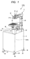
- FIG. 1 is a perspective view illustrating the robot system 1 according to an exemplary embodiment of the present invention.
- FIG. 2 is a block diagram illustrating the configuration of a control device 4 in the robot system 1 according to the exemplary embodiment.
- FIG. 3 is a block diagram illustrating the configuration of a camera control unit 5 according to the first embodiment.
- the robot system 1 includes a robot 2 for assembling a workpiece, a mounting base 3 on which the robot 2 assembles the workpiece, and the control device 4 for controlling the robot 2.
- the robot 2 is a six-axis articulated general-purpose robot including a robot arm 20, a hand 21 attached to the tip of the robot arm, a base camera 22 as a first camera, and a reference camera 23 as a second camera.
- a robot arm 20 a hand 21 attached to the tip of the robot arm
- a base camera 22 as a first camera
- a reference camera 23 as a second camera.
- two cameras i.e. the base camera 22 and the reference camera 23 are used, but a compound-eye camera such as a stereo camera may be used.
- the robot arm 20 is equipped with six actuators (not illustrated) for driving each joint to rotate about each joint axis.
- the six actuators are selectively driven, respectively, to move the hand 21 attached to the tip to any three-dimensional position.
- the hand 21 is equipped with a gripping portion 21a for gripping the workpiece and an actuator, not illustrated, for driving the gripping portion 21a.
- the hand 21 is moved by the driving of the robot arm 20 to a position in which the actuator is so driven that the hand 21 will grip the workpiece.
- a force sensor, not illustrated, is provided in the hand 21 to regulate a grip force when the workpiece is gripped.
- the hand 21 is detachably attached to the tip of the robot arm 20 in a manner to be changeable according to the shape of the workpiece to work on.
- the base camera 22 is attached to the tip of the robot arm 20 to capture an image of the workpiece in order to acquire a first image of the workpiece.
- the reference camera 23 is attached adjacent to the base camera 22 at the tip of the robot arm 20 to capture an image of the workpiece from a view point different from the base camera 22 in order to acquire a second image of the workpiece.
- the mounting base 3 is formed into a rectangular box shape, and provided with a planar placement section 30 with the workpiece placed on the top face thereof.
- a jig 31 used to assemble the workpiece is provided substantially in a central portion of the placement section 30.
- a support 32 for immovably supporting the base end section of the robot arm 20, a parts feeder 33, and a tool holder 34 are provided at the corners of the placement section 30, respectively.
- Four casters 35 for moving the mounting base 3 and four fixing brackets 36 for fixing the mounting base 3 to the floor are provided at the bottom of the mounting base 3 so that the mounting base 3 can be fixed after the mounting base 3 is moved to any position.
- the control device 4 is so configured that the robot arm 20, the hand 21, the base camera 22, and the reference camera 23 are connected through a bus to a computer main body having a calculating device 40 and a storing device 41.
- An input device 42, a teaching pendant 43, a display 44, a speaker 45, a recording medium reading device 46, a communication device 47, and the like are also connected to the computer main body through the bus. In FIG. 2 , interfaces for these connections are not illustrated.
- the calculating device 40 includes a CPU 40a, an image processing device 40b, and a sound processing device 40c.
- the CPU 40a includes a camera control unit 5 and a robot control unit 6.
- the camera control unit 5 measures the three-dimensional position of a workpiece according to various programs stored in the storing device 41 and the settings input from the input device 42.
- the camera control unit 5 includes a first image edge line extraction unit 51, a second image edge line extraction unit 52, a corresponding point calculation unit 53, a line-of-sight error calculation unit 54, an evaluation function setting unit 55, and a three-dimensional coordinate measurement unit 56.
- the first image edge line extraction unit 51 extracts a plurality of edge lines of the workpiece from a first image acquired by capturing the workpiece with the base camera 22.
- the second image edge line extraction unit 52 extracts a plurality of edge lines of the workpiece from a second image acquired by capturing the workpiece with the reference camera 23.
- the corresponding point calculation unit 53 extracts, from the plurality of edge lines of the second image, a second edge line corresponding to a first edge line arbitrarily selected from the plurality of edge lines of the first image, and calculates an endpoint of the extracted second edge line corresponding to an endpoint of the first edge line.
- the line-of-sight error calculation unit 54 sets provisional three-dimensional coordinates and calculates respective line-of-sight errors at the endpoint of the first edge line and the endpoint of the second edge line with respect to the provisional three-dimensional coordinates.
- the evaluation function setting unit 55 sets an evaluation function including the line-of-sight errors and three-dimensional constraint conditions from the line-of-sight errors respectively set at the endpoint of the first edge line and the endpoint of the second edge line, and the three-dimensional constraint conditions set based on the shape of the workpiece.
- the three-dimensional coordinate measurement unit 56 makes an optimization calculation to minimize or maximize the evaluation function in order to measure the three-dimensional coordinates of the workpiece. The measurement of the three-dimensional position of the workpiece by the camera control unit 5 will be described in detail later.
- the robot control unit 6 controls the robot arm 20 and the hand 21.
- the description of the control of the robot arm 20 and the hand 21 performed by the robot control unit 6 will be omitted.
- the image processing device 40b controls the display 44 in accordance with a drawing instruction from the CPU 40a to display a predetermined image on the screen.
- the sound processing device 40c generates a sound signal in accordance with a sound generation instruction from the CPU 40a to output the sound signal to the speaker 45.
- the storing device 41 is connected to the CPU 40a through the bus, and includes a ROM 41a in which the various programs and data are stored, and a RAM 41b reserved as a working area of the CPU 40a.
- the various programs for measuring the workpiece three-dimensionally are stored in the ROM 41a in addition to drive programs for the robot arm 20 and the hand 21.
- a three-dimensional measurement program for executing a first image edge line extraction process, a second image edge line extraction process, a corresponding point calculation process, a line-of-sight error calculation process, an evaluation function setting process, and a three-dimensional coordinate measurement process to be described later is stored.
- three-dimensional constraint conditions and data such as camera parameters of the base camera 22 and the reference camera 23, via the input device 42, these are also stored in the ROM 41a.
- the input device 42 includes a keyboard 42a and a mouse 42b to enable input of information necessary to measure the three-dimensional position of the workpiece and other instructions.
- the recording medium reading device 46 is used to read a computer-readable recording medium 48 that has recorded, for example, the three-dimensional measurement program, and to store the three-dimensional measurement program in the ROM 41a.
- the communication device 47 is used to download the three-dimensional measurement program distributed from the Internet through the communication device 47 without using the recording medium 48 mentioned above.
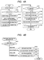
- FIG. 4A and FIG. 4B are flowcharts illustrating a measurement of three-dimensional coordinates according to the first embodiment.
- FIG. 5 is a schematic diagram illustrating the base camera 22, reference camera 23, and the workpiece according to the first embodiment.
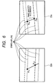
- FIG. 6 is a diagram for describing how to determine corresponding points using epipolar lines.
- FIG. 7 is a schematic diagram for describing line-of-sight errors at a first endpoint of the first edge line and a second endpoint of the second edge line.
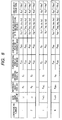
- FIG. 8 is a table illustrating a data structure when mapping is done between edge lines according to the first embodiment.
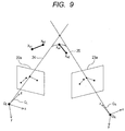
- FIG. 9 is a schematic diagram for describing a three-dimensional constraint condition between edge lines according to the first embodiment.
- each camera coordinate system is set to be perpendicular to each image plane with their origins at respective lens principal points O L and O R of the base camera 22 and the reference camera 23 placed to have a common field of view from different view points.
- a coordinate system representative of the base camera 22 is denoted as a base camera coordinate system C L
- a coordinate system representative of the reference camera 23 is denoted as a reference camera coordinate system C R
- the image plane of the base camera 22 is denoted as a base image plane 22a
- the image plane of the reference camera 23 is denoted as a reference image plane 23a.
- the internal parameters are parameters required to calculate a projection from any three-dimensional coordinates expressed in each camera coordinate system to a point on each image plane, which can be determined by a known camera calibration technique.
- the detailed description of how to calculate the internal parameters will be omitted, and the following expression is used as the internal parameters.
- f denotes the focal length of a lens
- c u denotes the column coordinate of an intersection point of the optical axis of a camera with an image plane
- c v denotes the row coordinate of the intersection point of the optical axis of the camera with the image plane
- s x denotes the width of an image sensor per pixel
- s y denotes the height of the image sensor per pixel.
- the column coordinate c u and the row coordinate c v means that an image pixel in the c u -th column from the left and the c v -th row from the top is the intersection point of the optical axis of the camera with the image plane.
- c u and c v do not need to be integers, which may be determined with subpixel accuracy.
- the focal distance f, the width s x per pixel, and the height s y per pixel are represented in typical units of length (e.g., millimeters or meters).
- the internal parameters of the base camera 22 can be expressed as (f L , c uL , c vL , s xL , s yL ), and the internal parameters of the reference camera 23 can be expressed as (f R , c uR , c vR , s xR , s yR ). Note that the subscript L indicates the internal parameters of the base camera 22, and the subscript R indicates the internal parameters of the reference camera 23.
- the external parameters are parameters representing relative postures of the base camera 22 and the reference camera 23 in six degrees of freedom, which can be determined by the known camera calibration technique.
- the detailed description of how to calculate the external parameters between the base camera 22 and the reference camera 23 will be omitted, and the external parameters are represented by a rotation matrix R and a translation vector t.
- the rotation matrix R and the translation vector t represent a coordinate transformation from the base camera coordinate system C L to the reference camera coordinate system C R , and any three-dimensional coordinates (R) X described in the reference camera coordinate system C R are expressed using the external parameters in the base camera coordinate system C L as follows.
- the subscripts (L) and (R) are used to make them clear to be the respective coordinate values expressed in the base camera coordinate system C L and the reference camera coordinate system C R .
- the base camera coordinate system is the entire base coordinate system, and the coordinates without any subscript indicative of a coordinate system are described in the base camera coordinate system.
- the internal parameters and external parameters of the cameras such as a matrix form, but it is not essential to use which form in the embodiment.
- no lens distortion is taken into account, but parameters that take the lens distortion into account may be used.
- the evaluation function for evaluating an error from a line of sight with respect to an image point and an error from a three-dimensional constraint condition assumes an important role.
- the evaluation function is denoted by F.
- the evaluation function F according to the embodiment is expressed as the sum of a line-of-sight error term portion and a three-dimensional constraint condition term portion.
- the line-of-sight error term portion of the evaluation function F is denoted by F sight(N) and the three-dimensional constraint condition term portion of the evaluation function F is denoted by F const(M) , i.e., the evaluation function F is given as follows.
- F F sight N + F const M
- the subscript N indicates the line-of-sight error term on the first to N-th edge mappings, and the subscript M indicates the constraint condition term at the time of setting M constraint conditions.
- a workpiece 10 is captured with the base camera 22 to acquire a base image 22b as the first image, and edge line extraction processing is performed on the acquired base image 22b to extract a plurality of edge lines of the workpiece 10 (step S101: first image edge line extraction process).
- an edge extraction filter such as Sobel filter or Canny filter is first used for the base image 22b to extract, as an edge point group, points at which the luminance change is maximized.
- linear approximation processing is performed on the extracted edge point group while dividing them into line segments to determine image coordinates (pixel position) of each endpoint.
- the image coordinates may take pixel-wise values, it is desired to use processing with subpixel accuracy in order to make a high accuracy measurement.
- edge line extraction processing is performed on a reference image 23b as the second image obtained by capturing the workpiece 10 with the reference camera 23 to extract a plurality of edge lines of the workpiece 10 (step S101: second image edge line extraction process).
- mapping processing is performed to identify where the plurality of edge lines extracted in the base image 22b are imaged in the reference image 23b, and the results are stored in the ROM 41a.
- mapping between the plurality of edge lines extracted from the base image 22b and the plurality of edge lines extracted from the reference image 23b is done and the results are stored.
- the mapping processing is continuously performed until the end of the mapping processing is determined (steps S102 to S106).
- the mapping may be done by specifying edge lines believed to be the same by a user while viewing images on a UI, or done by using a known technique in which the camera control unit 5 detects similar image patterns using image correlation to make a selection.
- one edge line is selected from the plurality of edge lines extracted from the base image 22b (step S103) to select an edge line (second edge line) corresponding thereto within the reference image 23b (step S104). Processing to be described below is performed on the associated first edge line and second edge line to determine one edge line in a three-dimensional space.
- step S101 for example, since the image coordinates of the endpoint of the selected first edge line are known, an intersection point of an epipolar line on the reference image 23b corresponding to the endpoint of the first edge line and the second edge line on the reference image 23b can be determined to determine the coordinates of a corresponding point.
- the epipolar constraints are used to determine a part imaged in common between the base image 22b and the reference image 23b in order to determine respective endpoints.
- epipolar lines indicated by the same type of broken line between the base image 22b and the reference image 23b correspond to each other. This corresponding point calculation processing is performed to determine the image coordinates of image points P Li1 , P Li2 , P Ri1 , and P Ri2 on the respective images with respect to i-th edge line correspondences.
- a line-of-sight error term on an unknown three-dimensional coordinates X ij is determined using the image coordinates of corresponding points determined in step S105 (step S106: line-of-sight error calculation process).
- the line-of-sight error term is so defined that the values thereof will be large according to distances d Lij , d Rij from the base image line of sight and the reference image line of sight to the three-dimensional coordinates X ij .
- the line-of-sight error term is so defined that the values thereof will be large according to distances d Lij , d Rij from the base image line of sight and the reference image line of sight to the three-dimensional coordinates X ij .
- the "distances d Lij , d Rij from the base image line of sight 24 and the reference image line of sight 25 to the three-dimensional coordinates X ij " are the lengths of perpendicular lines from the three-dimensional coordinates X ij to the base image line of sight 24 and the reference image line of sight 25, respectively.
- the sum of squared distances d Lij and d Rij from the base image line of sight 24 and the reference image line of sight 25 to the three-dimensional coordinates X ij is used as the line-of-sight error term.
- the line-of-sight unit vector e Lij and the line-of-sight unit vector e Rij in the base camera coordinate system are constants that can be determined uniquely using the corresponding points extracted from the images and the internal parameters and the external parameters of the cameras.
- step S106 the line-of-sight error term corresponding to the distances d Lij , d Rij between the unknown three-dimensional coordinates X ij and the lines of sight is added to the evaluation function.
- the sum of squared distances d Lij and d Rij is added to the evaluation function F. If the line-of-sight error term portion of the evaluation function F at the point of adding the i-th line-of-sight error term is written as F sight(i) , F sight(i) is given as follows.
- F sight i F sight ⁇ i - 1 + d Lij 2 + d Rij 2
- the line-of-sight error term portion F sight(N) of the evaluation function is a function having 6N variables (x 11 , y 11 , z 11 , x 12 , y 12 , z 12 , ..., x N1 , y N1 , z N1 , x N2 , y N2 , z N2 ).
- FIG. 8 an example of the mapping data structure at the point of exiting the loop is illustrated in FIG. 8 .
- image points P Li1 and P Li2 on the edge line L ⁇ (i) of the base image 22b and image points P Ri1 and P Ri2 on the edge line R ⁇ (i) of the reference image 23b are determined as corresponding points, respectively.
- step S107 it is determined whether to add a constraint condition. This determination may be made by entering the necessity of addition based on the user's discretion, or using an automatic determination algorithm. The subsequent processing steps S108 to S111 are repeated until the addition of constraint conditions is ended.
- two three-dimensional edge lines used to set the constraint conditions are selected. Note that one three-dimensional edge line corresponds to one combination set in steps S103 and S104. For example, E1 is selected in step S108 and E2 is selected in step S109 from a list of three-dimensional edge lines illustrated in FIG. 8 .
- a geometric three-dimensional constraint condition between edge lines is selected for the two edge lines selected in steps S108 and S109.
- an already known positional relationship between edge lines of the workpiece 10 is set.
- four kinds namely "two edge lines lie on the same plane," “two edge lines lie on the same straight line,” “the directions of two edge lines are parallel,” and “the directions of two edge lines are perpendicular" are handled.
- the procedure proceeds to step S111.
- a three-dimensional constraint condition term f const(k) is added to the evaluation function according to the three-dimensional constraint condition set in step S110 (see FIG. 4B ).
- a three-dimensional constraint condition term to be added is selected. The following will describe the content of a three-dimensional constraint condition term according to each three-dimensional constraint condition.
- steps S202 to S205 it is assumed that both endpoints of the edge line selected in step S108 are denoted by X a1 , X a2 and both endpoints of the edge line selected in step S109 are denoted by X b1 , X b2 .
- step S202 When a three-dimensional constraint condition that "two edge lines lie on the same plane (add same plane term: step S202)" is selected, the following processing is performed.
- the same plane term a function for minimizing the value thereof when two edge lines lie on the same plane is used.
- a condition that four points exist on the same plane can be expressed in the following equation because X a2 also exists on a plane with three points X a1 , X b1 , and X b2 .
- X a ⁇ 2 - X a ⁇ 1 • X b ⁇ 1 - X a ⁇ 1 ⁇ X b ⁇ 2 - X a ⁇ 1 0
- ⁇ k is a weighting factor that is a constant used to adjust weighting between different three-dimensional constraint conditions.
- the weighting factor ⁇ k may be set by the user individually or using an algorithm for determining weighting according to the length of each edge line.
- ⁇ k1 and ⁇ k2 are weighting factors that are constants used to adjust weighting between different three-dimensional constraint conditions.
- the weighting factors ⁇ k1 and ⁇ k2 may be set by the user individually or using an algorithm for determining weighting according to the length of each edge line.
- ⁇ k is a weighting factor that is a constant used to adjust weighting between different three-dimensional constraint conditions.
- the weighting factor ⁇ k may be set by any method.
- ⁇ k is a weighting factor that is a constant used to adjust weighting between different three-dimensional constraint conditions.
- the weighting factor ⁇ k may be set by any method.
- the constraint condition term f const(k) is a function having twelve variables (x a1 , y a1 , z a1 , x a2 , y a2 , z a2 , x b1 , y b1 , z b1 , x b2 , y b2 , z b2 ).
- step S111 After the constraint condition term f const(k) is added in step S111, the procedure returns to step S107 to determine whether further to add a three-dimensional constraint condition.
- the processing steps S108 to S111 are repeated until the addition of constraint conditions is ended.
- Any number of three-dimensional constraint condition terms f const(k) can be set within a consistent range. For example, two three-dimensional constraint conditions "on the same plane” and "perpendicular" can be set for certain two edge lines.
- the constraint condition term portion F const(M) of the evaluation function F is as follows.
- F const(M) is a function having 6N variables (x 11 , y 11 , z 11 , X 12 , y 12 , z 12 , ..., x N1 , y N1 , z N1 , x N2 , y N2 , z N2 ) at a maximum. Note that the actual number of variables included in F const(M) corresponds to the number of edge lines selected in steps S108 and S109.
- the evaluation function F is set (evaluation function setting process) from the line-of-sight error term portion F sight(N) added in steps S102 to S106 and the constraint condition term portion F const(M) added in the processing steps S107 to S111.
- the evaluation function F is expressed as the sum of the line-of-sight error term portion F sight(N) and the constraint condition term portion F const(M) , i.e., expressed as follows.
- the evaluation function F three-dimensional coordinate measurement process
- This calculation may be made by using a known multivariable optimization method.
- the Nelder-Mead downhill simplex method as one of nonlinear search techniques can be used.
- the coordinate values (x 11 , y 11 , z 11 , x 12 , y 12 , z 12 , ..., x N1 , y N1 , z N1 , x N2 , y N2 , z N2 ) determined by the above processing form a shape recreated in consideration of the three-dimensional constraint conditions between edge lines.
- any three-dimensional constraint condition can be applied between a plurality of edge lines stereoscopically arranged. Therefore, a highly accurate shape can be obtained in comparison with the conventional techniques.
- a robot system 1A according to a second embodiment of the present invention will be described with reference to FIG. 10 to FIG. 12 while using FIG. 1 and FIG. 2 .
- a method of measuring the three-dimensional coordinates of a workpiece by the camera control unit 5A is different from that in the first embodiment. Therefore, in the second embodiment, an emphasis is placed on a point different from the first embodiment, i.e. on the method of measuring the three-dimensional position by the camera control unit, and the same components as those in the first embodiment are given the same reference numerals to omit the description.
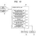
- FIG. 10 is a block diagram illustrating the configuration of a camera control unit 5A according to the second embodiment.
- the robot system 1A includes the robot 2, the mounting base 3, and a control device 4A for controlling the robot 2.
- the control device 4A includes a calculating device 40A and the storing device 41.
- the calculating device 40A includes a CPU 40aA, the image processing device 40b, and the sound processing device 40c.
- the CPU 40aA includes the camera control unit 5A and the robot control unit 6.
- the camera control unit 5A includes the first image edge line extraction unit 51, the second image edge line extraction unit 52, the corresponding point calculation unit 53, an error calculation unit 57, the evaluation function setting unit 55, and the three-dimensional coordinate measurement unit 56.
- the error calculation unit 57 sets provisional three-dimensional coordinates to calculate a line-of-sight error at an endpoint of a first edge line with respect to the provisional three-dimensional coordinates.
- the error calculation unit 57 also calculates a viewing plane error at an endpoint of a second edge line with respect to the provisional three-dimensional coordinates.
- FIG. 11A and 11B are flowcharts illustrating a measurement of three-dimensional coordinates according to the second embodiment.
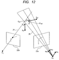
- FIG. 12 is a schematic diagram for describing a line-of-sight error and a viewing plane error according to the second embodiment.
- edge lines are first extracted from a base image 22b and a reference image 23b imaged with the base camera 22 and the reference camera 23 from a plurality of different view points (step S301).
- it is determined whether to repeat the addition of mapping step S302.
- a first edge line is selected from the plurality of edge lines of the base image 22b, and a corresponding second edge line is selected from the reference image 23b (mapping) (S303 and S304).
- a line-of-sight error term on the first edge line of the base image 22b is calculated (S305).
- a viewing plane error term on the reference image 23b is calculated (S306).
- a geometric three-dimensional constraint condition is set between mapped two edge lines to calculate a three-dimensional constraint condition term (S307 to S311).
- an optimization problem is solved so as to minimize the value of an evaluation function including the line-of-sight error term, the viewing plane error term, and the three-dimensional constraint condition term to determine the three-dimensional coordinates (S312).
- the processing steps S301 to S304 until the selection of the second edge line mapped after the selection of the first edge line are the same as those in the first embodiment.
- the processing steps S307 to S311 to add a three-dimensional constraint condition are also the same as those in the first embodiment. Therefore, the detailed description thereof will be omitted.
- the following will describe points different from the first embodiment, i.e. processing for adding a line-of-sight error term on an endpoint of the first edge line and adding a viewing plane error term on the second edge line (steps S305 and S306), and a calculation of the three-dimensional coordinates (S312).
- a line-of-sight error term on an endpoint of the first edge line selected in step S303 is determined and added to the evaluation function.
- a viewing plane error term is determined from both endpoints of the second edge line selected in step S304, and added to the evaluation function.
- the viewing plane error term is distance between unknown three-dimensional coordinates X and a viewing plane created by a point group on the selected second edge line.
- step S302 the processing for adding a constraint condition is performed in steps S307 to S311.
- the processing for adding a three-dimensional constraint condition is the same as the processing steps S107 to S111 in the first embodiment, the description thereof will be omitted.
- the same calculation formula can be applied as the three-dimensional constraint condition term.
- an evaluation function F is set by integrating the line-of-sight error term and the viewing plane error term added in steps S302 to S306, and the three-dimensional constraint condition term added in the processing steps S307 to S311 (evaluation function setting process).
- the evaluation function F is expressed as the sum of the error term portion F sight(N) and the constraint condition term portion F const(M) , i.e., expressed as follows.
- this calculation for determining the set of variables can be made by using a known multivariable optimization method.
- the need to perform processing for "uniquely determining corresponding points using the epipolar constraints" is eliminated to calculate the three-dimensional coordinates. This eliminates the need to determine corresponding points on the reference image 23b ahead with respect to the first edge line extracted from the base image 22b.
- the epipolar constraints are not satisfied due to an error in camera parameter or an error in extracting an edge line, the corresponding points become inaccurate in the case of using the method in which the corresponding points are determined. In this case, use of the method in the embodiment can reduce this influence.
- the description has been made by using two cameras, i.e. the base camera and the reference camera for the sake of simplicity, but the present invention is not limited thereto.
- the method of the present invention can be applied by adding a viewing plane error term with respect to each reference camera.
- images obtained by capturing the workpiece plural times while moving the same camera can also be used.
- the three-dimensional coordinates are determined by minimizing the value of the evaluation function in the embodiments, but the present invention is not limited thereto.
- the three-dimensional coordinates may be determined by maximizing the value of the evaluation function.
- Embodiments of the present invention can also be realized by a computer of a system or apparatus that reads out and executes computer executable instructions recorded on a storage medium (e.g., non-transitory computer-readable storage medium) to perform the functions of one or more of the above-described embodiment(s) of the present invention, and by a method performed by the computer of the system or apparatus by, for example, reading out and executing the computer executable instructions from the storage medium to perform the functions of one or more of the above-described embodiment(s).
- the computer may comprise one or more of a central processing unit (CPU), micro processing unit (MPU), or other circuitry, and may include a network of separate computers or separate computer processors.
- the computer executable instructions may be provided to the computer, for example, from a network or the storage medium.
- the storage medium may include, for example, one or more of a hard disk, a random-access memory (RAM), a read only memory (ROM), a storage of distributed computing systems, an optical disk (such as a compact disc (CD), digital versatile disc (DVD), or Blu-ray Disc (BD)TM), a flash memory device, a memory card, and the like.
- the three-dimensional measurement apparatus includes: a base camera for capturing a workpiece to acquire a first image; a reference camera for capturing the workpiece from a view point different from the base camera to acquire a second image; and a camera control unit for extracting multiple edge lines from the first and second images, calculating line-of-sight errors with respect to provisional three-dimensional coordinates, wherein the line-of-sight errors are calculated at an endpoint of a first edge line selected from the multiple edge lines of the first image and an endpoint of a second edge line extracted from the multiple edge lines of the second image to correspond to the first edge line, setting an evaluation function from the line-of-sight errors, and a three-dimensional constraint condition set based on a shape of the workpiece, and making an optimization calculation of the evaluation function to measure the three-dimensional coordinates of the workpiece.
Applications Claiming Priority (1)
| Application Number | Priority Date | Filing Date | Title |
|---|---|---|---|
| JP2012149596A JP6080407B2 (ja) | 2012-07-03 | 2012-07-03 | 3次元計測装置及びロボット装置 |
Publications (2)
| Publication Number | Publication Date |
|---|---|
| EP2682710A1 EP2682710A1 (en) | 2014-01-08 |
| EP2682710B1 true EP2682710B1 (en) | 2016-02-03 |
Family
ID=48699660
Family Applications (1)
| Application Number | Title | Priority Date | Filing Date |
|---|---|---|---|
| EP13174626.5A Not-in-force EP2682710B1 (en) | 2012-07-03 | 2013-07-02 | Apparatus and method for three-dimensional measurement and robot system comprising said apparatus |
Country Status (3)
| Country | Link |
|---|---|
| US (1) | US9715730B2 (ja) |
| EP (1) | EP2682710B1 (ja) |
| JP (1) | JP6080407B2 (ja) |
Families Citing this family (15)
| Publication number | Priority date | Publication date | Assignee | Title |
|---|---|---|---|---|
| US9879976B2 (en) | 2010-01-20 | 2018-01-30 | Faro Technologies, Inc. | Articulated arm coordinate measurement machine that uses a 2D camera to determine 3D coordinates of smoothly continuous edge features |
| US9628775B2 (en) | 2010-01-20 | 2017-04-18 | Faro Technologies, Inc. | Articulated arm coordinate measurement machine having a 2D camera and method of obtaining 3D representations |
| US9607239B2 (en) | 2010-01-20 | 2017-03-28 | Faro Technologies, Inc. | Articulated arm coordinate measurement machine having a 2D camera and method of obtaining 3D representations |
| ES2711199T3 (es) * | 2014-08-08 | 2019-04-30 | Sanovo Tech Italia S R L | Despaletizador para bandejas de huevos |
| DE112015004196T5 (de) * | 2014-09-15 | 2017-06-08 | Faro Technologies, Inc. | Gelenkarm-koordinatenmessgerät mit einer 2d-kamera und verfahren zum erhalten von 3d-darstellungen |
| JP6547754B2 (ja) * | 2014-09-18 | 2019-07-24 | 日本電気株式会社 | 三角測量装置、三角測量方法およびそのプログラム |
| JP5987073B2 (ja) * | 2015-02-12 | 2016-09-06 | ファナック株式会社 | 撮像部を用いたワークの位置決め装置 |
| EP3485109B1 (en) | 2016-07-15 | 2021-09-29 | Fastbrick IP Pty Ltd | Boom for material transport |
| WO2018009981A1 (en) | 2016-07-15 | 2018-01-18 | Fastbrick Ip Pty Ltd | Brick/block laying machine incorporated in a vehicle |
| CN111095355B (zh) | 2017-07-05 | 2023-10-20 | 快砖知识产权私人有限公司 | 实时定位和定向跟踪器 |
| CN111226090B (zh) | 2017-08-17 | 2023-05-23 | 快砖知识产权私人有限公司 | 具有改进的横滚角测量的激光跟踪器 |
| US11401115B2 (en) | 2017-10-11 | 2022-08-02 | Fastbrick Ip Pty Ltd | Machine for conveying objects and multi-bay carousel for use therewith |
| JP7000254B2 (ja) | 2018-06-01 | 2022-01-19 | トヨタ自動車株式会社 | ホイールアライメント調整システム |
| CN109493378B (zh) * | 2018-10-29 | 2021-05-28 | 宁波研新工业科技有限公司 | 一种基于单目视觉与双目视觉相结合的垂直度检测方法 |
| WO2021133183A1 (ru) * | 2019-12-23 | 2021-07-01 | федеральное государственное автономное образовательное учреждение высшего образования "Московский физико-технический институт (национальный исследовательский университет)" | Способ управления роботизированным манипулятором |
Family Cites Families (9)
| Publication number | Priority date | Publication date | Assignee | Title |
|---|---|---|---|---|
| KR100356016B1 (ko) | 1999-12-21 | 2002-10-18 | 한국전자통신연구원 | 영상인식에 의한 소포우편물 부피계측시스템 및부피계측방법 |
| JP3870255B2 (ja) | 2002-02-25 | 2007-01-17 | 独立行政法人産業技術総合研究所 | 3次元復元方法及び装置 |
| JP2006003157A (ja) * | 2004-06-16 | 2006-01-05 | Nippon Telegr & Teleph Corp <Ntt> | 位置検出システム |
| WO2006121088A1 (ja) | 2005-05-10 | 2006-11-16 | Olympus Corporation | 画像処理装置、画像処理方法および画像処理プログラム |
| JP4599515B2 (ja) * | 2005-05-27 | 2010-12-15 | コニカミノルタセンシング株式会社 | 3次元形状データの位置合わせ方法および装置 |
| JP2010117223A (ja) * | 2008-11-12 | 2010-05-27 | Fanuc Ltd | ロボットに取付けられたカメラを用いた三次元位置計測装置 |
| JP2010121999A (ja) * | 2008-11-18 | 2010-06-03 | Omron Corp | 3次元モデルの作成方法および物体認識装置 |
| JP5713624B2 (ja) * | 2009-11-12 | 2015-05-07 | キヤノン株式会社 | 三次元計測方法 |
| JP2011185650A (ja) * | 2010-03-05 | 2011-09-22 | Omron Corp | モデル作成装置およびモデル作成プログラム |
-
2012
- 2012-07-03 JP JP2012149596A patent/JP6080407B2/ja active Active
-
2013
- 2013-06-26 US US13/927,269 patent/US9715730B2/en active Active
- 2013-07-02 EP EP13174626.5A patent/EP2682710B1/en not_active Not-in-force
Also Published As
| Publication number | Publication date |
|---|---|
| JP2014013147A (ja) | 2014-01-23 |
| US20140009582A1 (en) | 2014-01-09 |
| JP6080407B2 (ja) | 2017-02-15 |
| EP2682710A1 (en) | 2014-01-08 |
| US9715730B2 (en) | 2017-07-25 |
Similar Documents
| Publication | Publication Date | Title |
|---|---|---|
| EP2682710B1 (en) | Apparatus and method for three-dimensional measurement and robot system comprising said apparatus | |
| JP5897624B2 (ja) | ワークの取出工程をシミュレーションするロボットシミュレーション装置 | |
| CN106457562B (zh) | 用于校准机器人的方法和机器人系统 | |
| JP5378374B2 (ja) | リアルオブジェクトに対するカメラの位置および方向を把握する方法およびシステム | |
| CN104057453B (zh) | 机器人装置以及被加工物的制造方法 | |
| JP4492654B2 (ja) | 3次元計測方法および3次元計測装置 | |
| US8874270B2 (en) | Apparatus for taking out bulk stored articles by robot | |
| CN103383238B (zh) | 图像测量设备、图像测量方法和图像测量程序 | |
| JP4021413B2 (ja) | 計測装置 | |
| US8964001B2 (en) | Method for displaying measurement effective area in three-dimensional visual sensor and three-dimensional visual sensor | |
| US9679385B2 (en) | Three-dimensional measurement apparatus and robot system | |
| CN108965690B (zh) | 图像处理系统、图像处理装置及计算机可读存储介质 | |
| JP6324025B2 (ja) | 情報処理装置、情報処理方法 | |
| JP7102115B2 (ja) | 校正方法、校正装置、3次元測定機、3次元視覚測定装置、ロボットのエンドエフェクタ、プログラム、記録媒体 | |
| US20170358048A1 (en) | Information processing apparatus, information processing method, and program | |
| CN105073348A (zh) | 用于校准的机器人系统和方法 | |
| JP2016103230A (ja) | 画像処理装置、画像処理方法、及びプログラム | |
| JP2012253758A (ja) | 車両視覚システムの較正方法および車両視覚システム | |
| CN103302666A (zh) | 信息处理设备和信息处理方法 | |
| CN104608121A (zh) | 机器人、控制装置、机器人系统以及控制方法 | |
| Bradley et al. | Binocular camera calibration using rectification error | |
| US20180290300A1 (en) | Information processing apparatus, information processing method, storage medium, system, and article manufacturing method | |
| CN114310901B (zh) | 用于机器人的坐标系标定方法、装置、系统以及介质 | |
| JP6973233B2 (ja) | 画像処理システム、画像処理装置および画像処理プログラム | |
| Yamauchi et al. | Calibration of a structured light system by observing planar object from unknown viewpoints |
Legal Events
| Date | Code | Title | Description |
|---|---|---|---|
| PUAI | Public reference made under article 153(3) epc to a published international application that has entered the european phase |
Free format text: ORIGINAL CODE: 0009012 |
|
| AK | Designated contracting states |
Kind code of ref document: A1 Designated state(s): AL AT BE BG CH CY CZ DE DK EE ES FI FR GB GR HR HU IE IS IT LI LT LU LV MC MK MT NL NO PL PT RO RS SE SI SK SM TR |
|
| AX | Request for extension of the european patent |
Extension state: BA ME |
|
| 17P | Request for examination filed |
Effective date: 20140318 |
|
| RBV | Designated contracting states (corrected) |
Designated state(s): AL AT BE BG CH CY CZ DE DK EE ES FI FR GB GR HR HU IE IS IT LI LT LU LV MC MK MT NL NO PL PT RO RS SE SI SK SM TR |
|
| GRAP | Despatch of communication of intention to grant a patent |
Free format text: ORIGINAL CODE: EPIDOSNIGR1 |
|
| RIC1 | Information provided on ipc code assigned before grant |
Ipc: G06T 7/00 20060101ALI20150626BHEP Ipc: G01B 11/00 20060101AFI20150626BHEP Ipc: H04N 13/02 20060101ALI20150626BHEP |
|
| INTG | Intention to grant announced |
Effective date: 20150716 |
|
| GRAS | Grant fee paid |
Free format text: ORIGINAL CODE: EPIDOSNIGR3 |
|
| GRAA | (expected) grant |
Free format text: ORIGINAL CODE: 0009210 |
|
| AK | Designated contracting states |
Kind code of ref document: B1 Designated state(s): AL AT BE BG CH CY CZ DE DK EE ES FI FR GB GR HR HU IE IS IT LI LT LU LV MC MK MT NL NO PL PT RO RS SE SI SK SM TR |
|
| REG | Reference to a national code |
Ref country code: GB Ref legal event code: FG4D |
|
| REG | Reference to a national code |
Ref country code: AT Ref legal event code: REF Ref document number: 773897 Country of ref document: AT Kind code of ref document: T Effective date: 20160215 Ref country code: CH Ref legal event code: EP |
|
| REG | Reference to a national code |
Ref country code: IE Ref legal event code: FG4D |
|
| REG | Reference to a national code |
Ref country code: DE Ref legal event code: R096 Ref document number: 602013004863 Country of ref document: DE |
|
| REG | Reference to a national code |
Ref country code: LT Ref legal event code: MG4D Ref country code: NL Ref legal event code: MP Effective date: 20160203 |
|
| REG | Reference to a national code |
Ref country code: AT Ref legal event code: MK05 Ref document number: 773897 Country of ref document: AT Kind code of ref document: T Effective date: 20160203 |
|
| PG25 | Lapsed in a contracting state [announced via postgrant information from national office to epo] |
Ref country code: NO Free format text: LAPSE BECAUSE OF FAILURE TO SUBMIT A TRANSLATION OF THE DESCRIPTION OR TO PAY THE FEE WITHIN THE PRESCRIBED TIME-LIMIT Effective date: 20160503 Ref country code: GR Free format text: LAPSE BECAUSE OF FAILURE TO SUBMIT A TRANSLATION OF THE DESCRIPTION OR TO PAY THE FEE WITHIN THE PRESCRIBED TIME-LIMIT Effective date: 20160504 Ref country code: HR Free format text: LAPSE BECAUSE OF FAILURE TO SUBMIT A TRANSLATION OF THE DESCRIPTION OR TO PAY THE FEE WITHIN THE PRESCRIBED TIME-LIMIT Effective date: 20160203 Ref country code: ES Free format text: LAPSE BECAUSE OF FAILURE TO SUBMIT A TRANSLATION OF THE DESCRIPTION OR TO PAY THE FEE WITHIN THE PRESCRIBED TIME-LIMIT Effective date: 20160203 Ref country code: IT Free format text: LAPSE BECAUSE OF FAILURE TO SUBMIT A TRANSLATION OF THE DESCRIPTION OR TO PAY THE FEE WITHIN THE PRESCRIBED TIME-LIMIT Effective date: 20160203 Ref country code: FI Free format text: LAPSE BECAUSE OF FAILURE TO SUBMIT A TRANSLATION OF THE DESCRIPTION OR TO PAY THE FEE WITHIN THE PRESCRIBED TIME-LIMIT Effective date: 20160203 |
|
| PG25 | Lapsed in a contracting state [announced via postgrant information from national office to epo] |
Ref country code: PL Free format text: LAPSE BECAUSE OF FAILURE TO SUBMIT A TRANSLATION OF THE DESCRIPTION OR TO PAY THE FEE WITHIN THE PRESCRIBED TIME-LIMIT Effective date: 20160203 Ref country code: SE Free format text: LAPSE BECAUSE OF FAILURE TO SUBMIT A TRANSLATION OF THE DESCRIPTION OR TO PAY THE FEE WITHIN THE PRESCRIBED TIME-LIMIT Effective date: 20160203 Ref country code: PT Free format text: LAPSE BECAUSE OF FAILURE TO SUBMIT A TRANSLATION OF THE DESCRIPTION OR TO PAY THE FEE WITHIN THE PRESCRIBED TIME-LIMIT Effective date: 20160603 Ref country code: NL Free format text: LAPSE BECAUSE OF FAILURE TO SUBMIT A TRANSLATION OF THE DESCRIPTION OR TO PAY THE FEE WITHIN THE PRESCRIBED TIME-LIMIT Effective date: 20160203 Ref country code: RS Free format text: LAPSE BECAUSE OF FAILURE TO SUBMIT A TRANSLATION OF THE DESCRIPTION OR TO PAY THE FEE WITHIN THE PRESCRIBED TIME-LIMIT Effective date: 20160203 Ref country code: AT Free format text: LAPSE BECAUSE OF FAILURE TO SUBMIT A TRANSLATION OF THE DESCRIPTION OR TO PAY THE FEE WITHIN THE PRESCRIBED TIME-LIMIT Effective date: 20160203 Ref country code: LT Free format text: LAPSE BECAUSE OF FAILURE TO SUBMIT A TRANSLATION OF THE DESCRIPTION OR TO PAY THE FEE WITHIN THE PRESCRIBED TIME-LIMIT Effective date: 20160203 Ref country code: IS Free format text: LAPSE BECAUSE OF FAILURE TO SUBMIT A TRANSLATION OF THE DESCRIPTION OR TO PAY THE FEE WITHIN THE PRESCRIBED TIME-LIMIT Effective date: 20160603 Ref country code: LV Free format text: LAPSE BECAUSE OF FAILURE TO SUBMIT A TRANSLATION OF THE DESCRIPTION OR TO PAY THE FEE WITHIN THE PRESCRIBED TIME-LIMIT Effective date: 20160203 |
|
| PG25 | Lapsed in a contracting state [announced via postgrant information from national office to epo] |
Ref country code: EE Free format text: LAPSE BECAUSE OF FAILURE TO SUBMIT A TRANSLATION OF THE DESCRIPTION OR TO PAY THE FEE WITHIN THE PRESCRIBED TIME-LIMIT Effective date: 20160203 Ref country code: DK Free format text: LAPSE BECAUSE OF FAILURE TO SUBMIT A TRANSLATION OF THE DESCRIPTION OR TO PAY THE FEE WITHIN THE PRESCRIBED TIME-LIMIT Effective date: 20160203 |
|
| REG | Reference to a national code |
Ref country code: DE Ref legal event code: R097 Ref document number: 602013004863 Country of ref document: DE |
|
| PG25 | Lapsed in a contracting state [announced via postgrant information from national office to epo] |
Ref country code: SK Free format text: LAPSE BECAUSE OF FAILURE TO SUBMIT A TRANSLATION OF THE DESCRIPTION OR TO PAY THE FEE WITHIN THE PRESCRIBED TIME-LIMIT Effective date: 20160203 Ref country code: RO Free format text: LAPSE BECAUSE OF FAILURE TO SUBMIT A TRANSLATION OF THE DESCRIPTION OR TO PAY THE FEE WITHIN THE PRESCRIBED TIME-LIMIT Effective date: 20160203 Ref country code: SM Free format text: LAPSE BECAUSE OF FAILURE TO SUBMIT A TRANSLATION OF THE DESCRIPTION OR TO PAY THE FEE WITHIN THE PRESCRIBED TIME-LIMIT Effective date: 20160203 Ref country code: CZ Free format text: LAPSE BECAUSE OF FAILURE TO SUBMIT A TRANSLATION OF THE DESCRIPTION OR TO PAY THE FEE WITHIN THE PRESCRIBED TIME-LIMIT Effective date: 20160203 |
|
| PLBE | No opposition filed within time limit |
Free format text: ORIGINAL CODE: 0009261 |
|
| STAA | Information on the status of an ep patent application or granted ep patent |
Free format text: STATUS: NO OPPOSITION FILED WITHIN TIME LIMIT |
|
| PG25 | Lapsed in a contracting state [announced via postgrant information from national office to epo] |
Ref country code: BE Free format text: LAPSE BECAUSE OF FAILURE TO SUBMIT A TRANSLATION OF THE DESCRIPTION OR TO PAY THE FEE WITHIN THE PRESCRIBED TIME-LIMIT Effective date: 20160203 |
|
| 26N | No opposition filed |
Effective date: 20161104 |
|
| PG25 | Lapsed in a contracting state [announced via postgrant information from national office to epo] |
Ref country code: SI Free format text: LAPSE BECAUSE OF FAILURE TO SUBMIT A TRANSLATION OF THE DESCRIPTION OR TO PAY THE FEE WITHIN THE PRESCRIBED TIME-LIMIT Effective date: 20160203 Ref country code: BG Free format text: LAPSE BECAUSE OF FAILURE TO SUBMIT A TRANSLATION OF THE DESCRIPTION OR TO PAY THE FEE WITHIN THE PRESCRIBED TIME-LIMIT Effective date: 20160503 |
|
| REG | Reference to a national code |
Ref country code: CH Ref legal event code: PL |
|
| PG25 | Lapsed in a contracting state [announced via postgrant information from national office to epo] |
Ref country code: MC Free format text: LAPSE BECAUSE OF FAILURE TO SUBMIT A TRANSLATION OF THE DESCRIPTION OR TO PAY THE FEE WITHIN THE PRESCRIBED TIME-LIMIT Effective date: 20160203 |
|
| PG25 | Lapsed in a contracting state [announced via postgrant information from national office to epo] |
Ref country code: FR Free format text: LAPSE BECAUSE OF NON-PAYMENT OF DUE FEES Effective date: 20160801 Ref country code: CH Free format text: LAPSE BECAUSE OF NON-PAYMENT OF DUE FEES Effective date: 20160731 Ref country code: LI Free format text: LAPSE BECAUSE OF NON-PAYMENT OF DUE FEES Effective date: 20160731 |
|
| REG | Reference to a national code |
Ref country code: FR Ref legal event code: ST Effective date: 20170331 |
|
| REG | Reference to a national code |
Ref country code: IE Ref legal event code: MM4A |
|
| PG25 | Lapsed in a contracting state [announced via postgrant information from national office to epo] |
Ref country code: IE Free format text: LAPSE BECAUSE OF NON-PAYMENT OF DUE FEES Effective date: 20160702 |
|
| PG25 | Lapsed in a contracting state [announced via postgrant information from national office to epo] |
Ref country code: LU Free format text: LAPSE BECAUSE OF NON-PAYMENT OF DUE FEES Effective date: 20160702 |
|
| GBPC | Gb: european patent ceased through non-payment of renewal fee |
Effective date: 20170702 |
|
| PG25 | Lapsed in a contracting state [announced via postgrant information from national office to epo] |
Ref country code: GB Free format text: LAPSE BECAUSE OF NON-PAYMENT OF DUE FEES Effective date: 20170702 |
|
| PG25 | Lapsed in a contracting state [announced via postgrant information from national office to epo] |
Ref country code: CY Free format text: LAPSE BECAUSE OF FAILURE TO SUBMIT A TRANSLATION OF THE DESCRIPTION OR TO PAY THE FEE WITHIN THE PRESCRIBED TIME-LIMIT Effective date: 20160203 Ref country code: HU Free format text: LAPSE BECAUSE OF FAILURE TO SUBMIT A TRANSLATION OF THE DESCRIPTION OR TO PAY THE FEE WITHIN THE PRESCRIBED TIME-LIMIT; INVALID AB INITIO Effective date: 20130702 |
|
| PG25 | Lapsed in a contracting state [announced via postgrant information from national office to epo] |
Ref country code: MK Free format text: LAPSE BECAUSE OF FAILURE TO SUBMIT A TRANSLATION OF THE DESCRIPTION OR TO PAY THE FEE WITHIN THE PRESCRIBED TIME-LIMIT Effective date: 20160203 Ref country code: MT Free format text: LAPSE BECAUSE OF NON-PAYMENT OF DUE FEES Effective date: 20160731 Ref country code: TR Free format text: LAPSE BECAUSE OF FAILURE TO SUBMIT A TRANSLATION OF THE DESCRIPTION OR TO PAY THE FEE WITHIN THE PRESCRIBED TIME-LIMIT Effective date: 20160203 |
|
| PG25 | Lapsed in a contracting state [announced via postgrant information from national office to epo] |
Ref country code: AL Free format text: LAPSE BECAUSE OF FAILURE TO SUBMIT A TRANSLATION OF THE DESCRIPTION OR TO PAY THE FEE WITHIN THE PRESCRIBED TIME-LIMIT Effective date: 20160203 |
|
| PGFP | Annual fee paid to national office [announced via postgrant information from national office to epo] |
Ref country code: DE Payment date: 20220621 Year of fee payment: 10 |
|
| REG | Reference to a national code |
Ref country code: DE Ref legal event code: R119 Ref document number: 602013004863 Country of ref document: DE |