EP2682686B1 - Dispositif de réfrigération et de climatisation - Google Patents
Dispositif de réfrigération et de climatisation Download PDFInfo
- Publication number
- EP2682686B1 EP2682686B1 EP11860082.4A EP11860082A EP2682686B1 EP 2682686 B1 EP2682686 B1 EP 2682686B1 EP 11860082 A EP11860082 A EP 11860082A EP 2682686 B1 EP2682686 B1 EP 2682686B1
- Authority
- EP
- European Patent Office
- Prior art keywords
- indoor
- heat exchanger
- unit
- temperature
- side heat
- Prior art date
- Legal status (The legal status is an assumption and is not a legal conclusion. Google has not performed a legal analysis and makes no representation as to the accuracy of the status listed.)
- Active
Links
- 238000004378 air conditioning Methods 0.000 title claims description 69
- 238000005057 refrigeration Methods 0.000 title claims description 8
- 239000003507 refrigerant Substances 0.000 claims description 122
- 238000010438 heat treatment Methods 0.000 claims description 69
- 238000001816 cooling Methods 0.000 claims description 50
- 230000005540 biological transmission Effects 0.000 claims description 46
- 238000000034 method Methods 0.000 description 108
- XLYOFNOQVPJJNP-UHFFFAOYSA-N water Substances O XLYOFNOQVPJJNP-UHFFFAOYSA-N 0.000 description 82
- 239000007788 liquid Substances 0.000 description 34
- 238000004891 communication Methods 0.000 description 10
- 238000010586 diagram Methods 0.000 description 10
- 239000000758 substrate Substances 0.000 description 7
- 238000004458 analytical method Methods 0.000 description 6
- 230000001276 controlling effect Effects 0.000 description 6
- 238000012545 processing Methods 0.000 description 5
- 238000012546 transfer Methods 0.000 description 5
- 238000001514 detection method Methods 0.000 description 4
- 238000009434 installation Methods 0.000 description 4
- 230000002159 abnormal effect Effects 0.000 description 3
- 230000002528 anti-freeze Effects 0.000 description 2
- 238000004364 calculation method Methods 0.000 description 2
- 238000006243 chemical reaction Methods 0.000 description 2
- 238000005516 engineering process Methods 0.000 description 2
- 238000012937 correction Methods 0.000 description 1
- 230000007547 defect Effects 0.000 description 1
- 230000000694 effects Effects 0.000 description 1
- 230000001105 regulatory effect Effects 0.000 description 1
Images


Classifications
-
- F—MECHANICAL ENGINEERING; LIGHTING; HEATING; WEAPONS; BLASTING
- F25—REFRIGERATION OR COOLING; COMBINED HEATING AND REFRIGERATION SYSTEMS; HEAT PUMP SYSTEMS; MANUFACTURE OR STORAGE OF ICE; LIQUEFACTION SOLIDIFICATION OF GASES
- F25B—REFRIGERATION MACHINES, PLANTS OR SYSTEMS; COMBINED HEATING AND REFRIGERATION SYSTEMS; HEAT PUMP SYSTEMS
- F25B13/00—Compression machines, plants or systems, with reversible cycle
-
- F—MECHANICAL ENGINEERING; LIGHTING; HEATING; WEAPONS; BLASTING
- F25—REFRIGERATION OR COOLING; COMBINED HEATING AND REFRIGERATION SYSTEMS; HEAT PUMP SYSTEMS; MANUFACTURE OR STORAGE OF ICE; LIQUEFACTION SOLIDIFICATION OF GASES
- F25B—REFRIGERATION MACHINES, PLANTS OR SYSTEMS; COMBINED HEATING AND REFRIGERATION SYSTEMS; HEAT PUMP SYSTEMS
- F25B49/00—Arrangement or mounting of control or safety devices
- F25B49/02—Arrangement or mounting of control or safety devices for compression type machines, plants or systems
-
- F—MECHANICAL ENGINEERING; LIGHTING; HEATING; WEAPONS; BLASTING
- F25—REFRIGERATION OR COOLING; COMBINED HEATING AND REFRIGERATION SYSTEMS; HEAT PUMP SYSTEMS; MANUFACTURE OR STORAGE OF ICE; LIQUEFACTION SOLIDIFICATION OF GASES
- F25B—REFRIGERATION MACHINES, PLANTS OR SYSTEMS; COMBINED HEATING AND REFRIGERATION SYSTEMS; HEAT PUMP SYSTEMS
- F25B25/00—Machines, plants or systems, using a combination of modes of operation covered by two or more of the groups F25B1/00 - F25B23/00
- F25B25/005—Machines, plants or systems, using a combination of modes of operation covered by two or more of the groups F25B1/00 - F25B23/00 using primary and secondary systems
-
- F—MECHANICAL ENGINEERING; LIGHTING; HEATING; WEAPONS; BLASTING
- F25—REFRIGERATION OR COOLING; COMBINED HEATING AND REFRIGERATION SYSTEMS; HEAT PUMP SYSTEMS; MANUFACTURE OR STORAGE OF ICE; LIQUEFACTION SOLIDIFICATION OF GASES
- F25B—REFRIGERATION MACHINES, PLANTS OR SYSTEMS; COMBINED HEATING AND REFRIGERATION SYSTEMS; HEAT PUMP SYSTEMS
- F25B49/00—Arrangement or mounting of control or safety devices
- F25B49/005—Arrangement or mounting of control or safety devices of safety devices
-
- F—MECHANICAL ENGINEERING; LIGHTING; HEATING; WEAPONS; BLASTING
- F25—REFRIGERATION OR COOLING; COMBINED HEATING AND REFRIGERATION SYSTEMS; HEAT PUMP SYSTEMS; MANUFACTURE OR STORAGE OF ICE; LIQUEFACTION SOLIDIFICATION OF GASES
- F25B—REFRIGERATION MACHINES, PLANTS OR SYSTEMS; COMBINED HEATING AND REFRIGERATION SYSTEMS; HEAT PUMP SYSTEMS
- F25B2313/00—Compression machines, plants or systems with reversible cycle not otherwise provided for
- F25B2313/023—Compression machines, plants or systems with reversible cycle not otherwise provided for using multiple indoor units
- F25B2313/0231—Compression machines, plants or systems with reversible cycle not otherwise provided for using multiple indoor units with simultaneous cooling and heating
-
- F—MECHANICAL ENGINEERING; LIGHTING; HEATING; WEAPONS; BLASTING
- F25—REFRIGERATION OR COOLING; COMBINED HEATING AND REFRIGERATION SYSTEMS; HEAT PUMP SYSTEMS; MANUFACTURE OR STORAGE OF ICE; LIQUEFACTION SOLIDIFICATION OF GASES
- F25B—REFRIGERATION MACHINES, PLANTS OR SYSTEMS; COMBINED HEATING AND REFRIGERATION SYSTEMS; HEAT PUMP SYSTEMS
- F25B2313/00—Compression machines, plants or systems with reversible cycle not otherwise provided for
- F25B2313/027—Compression machines, plants or systems with reversible cycle not otherwise provided for characterised by the reversing means
- F25B2313/0272—Compression machines, plants or systems with reversible cycle not otherwise provided for characterised by the reversing means using bridge circuits of one-way valves
-
- F—MECHANICAL ENGINEERING; LIGHTING; HEATING; WEAPONS; BLASTING
- F25—REFRIGERATION OR COOLING; COMBINED HEATING AND REFRIGERATION SYSTEMS; HEAT PUMP SYSTEMS; MANUFACTURE OR STORAGE OF ICE; LIQUEFACTION SOLIDIFICATION OF GASES
- F25B—REFRIGERATION MACHINES, PLANTS OR SYSTEMS; COMBINED HEATING AND REFRIGERATION SYSTEMS; HEAT PUMP SYSTEMS
- F25B2313/00—Compression machines, plants or systems with reversible cycle not otherwise provided for
- F25B2313/027—Compression machines, plants or systems with reversible cycle not otherwise provided for characterised by the reversing means
- F25B2313/02741—Compression machines, plants or systems with reversible cycle not otherwise provided for characterised by the reversing means using one four-way valve
-
- F—MECHANICAL ENGINEERING; LIGHTING; HEATING; WEAPONS; BLASTING
- F25—REFRIGERATION OR COOLING; COMBINED HEATING AND REFRIGERATION SYSTEMS; HEAT PUMP SYSTEMS; MANUFACTURE OR STORAGE OF ICE; LIQUEFACTION SOLIDIFICATION OF GASES
- F25B—REFRIGERATION MACHINES, PLANTS OR SYSTEMS; COMBINED HEATING AND REFRIGERATION SYSTEMS; HEAT PUMP SYSTEMS
- F25B2313/00—Compression machines, plants or systems with reversible cycle not otherwise provided for
- F25B2313/031—Sensor arrangements
- F25B2313/0314—Temperature sensors near the indoor heat exchanger
Definitions
- the present invention relates to refrigerating and air-conditioning apparatuses, and particularly, to a refrigerating and air-conditioning apparatus equipped with a plurality of use-side heat exchangers.
- WO 2010/1069571 A1 discloses: An air conditioner that is provided with a heat source device for supplying a refrigerant; a relay unit which exchanges heat between the refrigerant, supplied from the heat source device, and a heat medium such as water or antifreeze liquid by using an intermediate heat exchanger and supplies the heat medium; an indoor unit for exchanging heat between indoor air and a utilization heat exchanger in which the heat medium supplied from the relay unit flows and cooling or heating an indoor space; a control device for controlling operations of the heat source device, the relay unit, and the indoor unit; and a third temperature sensor for detecting the temperature of the heat medium flowing in the utilization heat exchanger.
- WO 2010/109627 A1 shows: In an information conveyance system for a refrigerating/air-conditioning device in which one or plural heat source units of a refrigerating/air conditioning device, one first relay unit, and one or plural second relay units are connected by refrigerant pipes, and the second relay units and one or plural indoor units are connected by water pipes, communication is performed only between the heat source unit and the first relay unit, between the first relay unit and the second relay units, and between the second relay units and the indoor units vie transmission lines.
- WO 2010/049999 A1 discloses: An air conditioner in which the refrigerant is adapted not to flow up to an indoor unit to further save energy.
- the air conditioner has a refrigeration cycle circuit formed by interconnecting by piping a compressor for pressuring the refrigerant, a four-way valve for switching a refrigerant circulation path, a heat source-side heat exchanger, an expansion valve for regulating the pressure of the refrigerant, and intermediate heat exchangers for heating and cooling a heat medium by exchanging heat between the heat medium and the refrigerant.
- Patent Literature 1 Japanese Unexamined Patent Application Publication No. 9-229457 (Abstract)
- a relay unit In a refrigerating and air-conditioning apparatus in the related art that can simultaneously perform cooling and heating, a relay unit is provided with a plurality of branch ports for a refrigerant pipe, and indoor units are connected to the respective branch ports. Because the relay unit needs to control flow switching valves and the like based on whether the indoor units are in operation or are stopped or whether the indoor units are operating in a cooling mode or a heating mode, it is necessary to perform the control by identifying which indoor unit is connected to which branch port. Therefore, connected-branch-port numbers or connected-indoor-unit numbers need to be set at the indoor units or the relay unit by using DIP switches or the like.
- each indoor unit or the relay unit requires setting means, such as a DIP switch, which involves a problem in that the component cost is increased and a troublesome task is required in the setting process.
- setting means such as a DIP switch
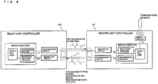
- Fig. 8 is a schematic diagram illustrating the configuration of an indoor-unit controller and a relay-unit controller in the related art provided with a function for controlling a flow control valve and measuring a temperature change in an indoor heat exchanger so as to automatically determine the connection.
- a relay-unit controller 63b and an indoor-unit controller 62 are connected by transmission lines 71.
- the transmission lines 71 connect transmission circuits and reception circuits of the relay-unit controller 63b and the indoor-unit controller 62.
- the transmission circuit and the reception circuit in each controller are connected to a microcomputer in the controller, and the microcomputer performs a transmission process and a reception analysis process.
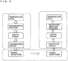
- Fig. 9 illustrates the flow of data when transmitting temperature data of an indoor heat exchanger from the indoor-unit controller 62 to the relay-unit controller 63b in the related art.
- the temperature data is converted into a transmittable digital signal by a transmission process performed by the indoor-unit controller 62.
- the digital signal is converted into a signal waveform by the transmission circuit, and the signal waveform is transmitted to the relay unit via the transmission line.
- the reception circuit reversely-converts the signal waveform into a digital signal.
- the digital signal is reversely-converted into temperature data by a reception analysis process so that the temperature data can be received.
- the relay unit and each indoor unit are connectable only if the combination thereof satisfies the limiting conditions thereof. This is a problem in that the units cannot be readily connected if they are products provided by different manufacturers.
- the present invention has been made to solve the aforementioned problems, and a first object thereof is to provide a refrigerating and air-conditioning apparatus that achieves reduced limitations with respect to the communication of indoor units and can identify which indoor unit is connected to each branch port.
- a second object is to provide a refrigerating and air-conditioning apparatus that can detect a setting error with respect to the connection between each branch port and each indoor unit.
- a refrigerating and air-conditioning apparatus is defined by claim 1. It includes a refrigeration cycle that makes a refrigerant circulate therethrough by connecting a compressor, a heat-source-side heat exchanger, at least one expansion valve, and at least one intermediate heat exchanger; and a heat-medium circuit that makes a heat medium circulate therethrough by connecting at least one pump, a plurality of use-side heat exchangers, and the intermediate heat exchanger.
- the at least one intermediate heat exchanger and the pump are accommodated in a relay unit.
- the plurality of use-side heat exchangers are accommodated in respective indoor units.
- Each indoor unit includes an indoor-unit controller that performs on-off control for operation performed by the use-side heat exchanger for exchanging heat between the heat medium and a thermal load.
- the relay unit includes a plurality of branch ports that are connected to the plurality of use-side heat exchangers and make the heat medium circulate to the use-side heat exchangers, outlet temperature sensors that are provided for the respective branch ports and each detect an outlet temperature of the heat medium flowing out of the branch port to the corresponding use-side heat exchanger, inlet temperature sensors that are provided for the respective branch ports and each detect an inlet temperature of the heat medium flowing into the branch port from the corresponding use-side heat exchanger, and a relay-unit controller that is connected to the indoor-unit controllers by a transmission line and controls operation of each indoor-unit by transmitting an operation command or a stop command thereto via the transmission line.
- the relay-unit controller makes the indoor units operate on a one-by-one basis and identifies which of the indoor units is connected to the respective branch port on the basis of a
- the present invention can achieve reduced limitations with respect to the communication of indoor units and can identify which indoor unit is connected to each branch port.
- Embodiment 1 relates to a refrigerating and air-conditioning apparatus that performs an process of automatic determination of connected branch ports to indoor units during trial operation performed after installation of the apparatus.
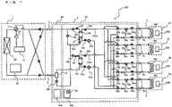
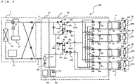
- Fig. 1 is a schematic circuit diagram illustrating the configuration of the refrigerating and air-conditioning apparatus according to Embodiment 1 of the present invention.
- the refrigerating and air-conditioning apparatus includes a single heat source device 1 serving as a heat source unit, a plurality of indoor units 2, and a relay unit 3 interposed between the heat source device 1 and the indoor units 2.
- the heat source device 1 accommodates a compressor 10, a four-way valve 11, a heat-source-side heat exchanger 12, and an accumulator 17 that are connected in series by a refrigerant pipe 4, and serves as a system that supplies required heat by means of a refrigerant.
- the indoor units 2 are individually equipped with use-side heat exchangers 26.
- the use-side heat exchangers 26 are connected to stop valves 24 and flow control valves 25 in a second relay unit 3b via pipes 5.
- the indoor units 2 transfer heat from a heat medium circulated by the use-side heat exchangers 26 to indoor air by heat exchange.
- the heat medium used may be water, an antifreeze, or the like. In Embodiment 1, water is used as the heat medium.
- the relay unit 3 is constituted of a first relay unit 3a and the second relay unit 3b that are accommodated in separate housings.
- the first relay unit 3a is provided with a gas-liquid separator 14 and an expansion valve 16e, and separates a transported refrigerant into three, that is, high-pressure gas, intermediate-pressure liquid, and low-pressure gas and supplies the refrigerant as a heat source for cooling and heating.
- the second relay unit 3b is provided with two intermediate heat exchangers 15, four expansion valves 16, two pumps 21, four flow switching valves 22, four flow switching valves 23, four stop valves 24, and four flow control valves 25.
- the second relay unit 3b transfers required heat from a cooling or heating refrigerant to water and causes the water storing a required amount of heat to circulate to a heat-medium circuit (water circuit).
- the second relay unit 3b is further provided with two first temperature sensors 31, two second temperature sensors 32, four third temperature sensors 33, four fourth temperature sensors 34, a fifth temperature sensor 35, a pressure sensor 36, a sixth temperature sensor 37, and a seventh temperature sensor 38.
- the four third temperature sensors 33 (third temperature sensors 33a to 33d) are provided at the inlet side of heat-medium passages of the use-side heat exchangers 26, are configured to detect the temperature of the heat medium flowing into the use-side heat exchangers 26, and may be formed of thermistors or the like.
- the number of third temperature sensors 33 provided corresponds the number of (four, in this case) indoor units 2 installed. In line with the indoor units 2, the third temperature sensor 33a, the third temperature sensor 33b, the third temperature sensor 33c, and the third temperature sensor 33d are shown in that order from the lower side of the drawing.
- the third temperature sensors 33 correspond to "inlet temperature sensors" in the present invention.
- the four fourth temperature sensors 34 are provided at the outlet side of the heat-medium passages of the use-side heat exchangers 26, are configured to detect the temperature of the heat medium flowing out of the use-side heat exchangers 26, and may be formed of thermistors or the like.
- the number of fourth temperature sensors 34 provided corresponds to the number of (four, in this case) indoor units 2 installed. In line with the indoor units 2, the fourth temperature sensor 34a, the fourth temperature sensor 34b, the fourth temperature sensor 34c, and the fourth temperature sensor 34d are shown in that order from the lower side of the drawing.
- the fourth temperature sensors 34 correspond to "outlet temperature sensors" in the present invention.
- the pipes 5 that guide the water serving as a heat medium include a pipe (referred to as “pipe 5a” hereinafter) that is connected to the intermediate heat exchanger 15a and a pipe (referred to as “pipe 5b” hereinafter) that is connected to the intermediate heat exchanger 15b.
- the pipe 5a and the pipe 5b each branch off into pipe segments (four pipe segments, in this case) in accordance with the number of indoor units 2 connectable to the relay unit 3.
- Combinations of branch pipe segments of the pipes 5a and 5b that are connectable to the indoor units 2a to 2d will be referred to as branch ports 6a to 6d.
- the branch ports 6a to 6d are connected to each other by the flow switching valves 22, the flow switching valves 23, and the flow control valves 25.
- the heat medium guided through the pipe 5a can be made to flow into the use-side heat exchangers 26, or the heat medium guided through the pipe 5b can be made to flow into the use-side heat exchangers 26.
- the heat source device 1 is provided with a controller 61 that controls the operation of each of the devices included in the heat source device 1.
- the indoor units 2a to 2d are respectively provided with indoor-unit controllers 62a to 62d that control the operation of each of the devices included in each of the indoor units 2a to 2d.
- the relay units 3a and 3b are respectively provided with relay-unit controllers 63a and 63b that control the operation of each of the devices included in the relay units 3a and 3b.
- the relay-unit controller 63b is provided with a switch 64 that is to be operated when commencing the automatic determination process for branch ports.
- the controller 61, the indoor-unit controllers 62a to 62d, and the relay-unit controllers 63a and 63b are capable of exchanging signals with each other.
- the number of connected heat source devices 1, indoor units 2, and relay units 3 is not limited to that shown in the drawing.
- the indoor units 2 are not limited to air-conditioning units, and may alternatively be hot-water-supply units.
- the refrigerating and air-conditioning apparatus 100 can perform cooling operation or heating operation in each indoor unit 2. Specifically, the refrigerating and air-conditioning apparatus 100 can perform the same operation in all of the indoor units 2 or perform different operations among the indoor units 2.
- Four operation modes executable by the refrigerating and air-conditioning apparatus 100 that is, a cooling only operation mode in which all of the driven indoor units 2 perform the cooling operation, a heating only operation mode in which all of the driven indoor units 2 perform the heating operation, a cooling main operation mode in which the cooling load is the greater, and a heating main operation mode in which the heating load is the greater, will be described below together with the flow of the refrigerant.
- the following description relates to an example of a cooling only operation mode in a case where a cooling load is generated only in a use-side heat exchanger 26a and a use-side heat exchanger 26b.
- the four-way valve 11 in the heat source device 1 is switched so that the refrigerant discharged from the compressor 10 flows into the heat-source-side heat exchanger 12.
- the pump 21a is stopped, the pump 21b is driven, the stop valve 24a and the stop valve 24b are opened, and the stop valve 24c and the stop valve 24d are closed, so that the heat medium circulates between the intermediate heat exchanger 15b and the corresponding use-side heat exchangers 26 (the use-side heat exchanger 26a and the use-side heat exchanger 26b).
- the operation of the compressor 10 commences.
- a low-temperature low-pressure gas refrigerant is compressed by the compressor 10 and is discharged therefrom as a high-temperature high-pressure gas refrigerant.
- the high-temperature high-pressure gas refrigerant discharged from the compressor 10 travels through the four-way valve 11 so as to flow into the heat-source-side heat exchanger 12. Then, the refrigerant condenses and liquefies while transferring heat to outdoor air at the heat-source-side heat exchanger 12, thereby becoming a high-pressure liquid refrigerant.
- the high-pressure liquid refrigerant flowing out of the heat-source-side heat exchanger 12 flows out of the heat source device 1 via a check valve, and then travels through the refrigerant pipe 4 so as to flow into the first relay unit 3a.
- the high-pressure liquid refrigerant flowing into the first relay unit 3a flows into the gas-liquid separator 14 and then travels through the expansion valve 16e before flowing into the second relay unit 3b.
- the refrigerant flowing into the second relay unit 3b is expanded by being throttled by an expansion valve 16a, thereby becoming a low-temperature low-pressure two-phase gas-liquid refrigerant.
- This two-phase gas-liquid refrigerant flows into the intermediate heat exchanger 15b functioning as an evaporator and cools the heat medium circulating through the heat-medium circuit by receiving heat from the heat medium, thereby becoming a low-temperature low-pressure gas refrigerant.
- the gas refrigerant flowing out of the intermediate heat exchanger 15b flows out of the second relay unit 3b and the first relay unit 3a after traveling through an expansion valve 16c, and then travels through the refrigerant pipe 4 so as to flow into the heat source device 1.
- the refrigerant flowing into the heat source device 1 travels through a check valve and is suctioned into the compressor 10 again via the four-way valve 11 and the accumulator 17.
- the expansion valve 16b and the expansion valve 16d are set to small opening degrees so as to prevent the refrigerant from flowing therethrough, whereas the expansion valve 16c is completely opened so as to prevent the occurrence of pressure loss.
- the heat medium circulates via the pipe 5b since the pump 21a is stopped.
- the heat medium cooled by the refrigerant at the intermediate heat exchanger 15b is made to flow through the pipe 5b by the pump 21b.
- the heat medium pressurized by and flowing out of the pump 21b travels through the stop valves 24 (the stop valve 24a and the stop valve 24b) via the flow switching valves 22 (the flow switching valve 22a and the flow switching valve 22b) so as to flow into the use-side heat exchangers 26 (the use-side heat exchanger 26a and the use-side heat exchanger 26b).
- the heat medium receives heat from indoor air (thermal load) at the use-side heat exchangers 26, thereby cooling an air-conditioning target area, such as an indoor area, where the indoor units 2 are installed.
- the heat medium flowing out of the use-side heat exchangers 26 flows into the flow control valves 25 (the flow control valve 25a and the flow control valve 25b).
- the functions of the flow control valves 25 only an amount of heat medium sufficient to cover the air-conditioning load required in the air-conditioning target area, such as an indoor area, flows into the use-side heat exchangers 26, whereas the remaining heat medium bypasses the use-side heat exchangers 26 by flowing through bypass pipes 27 (a bypass pipe 27a and a bypass pipe 27b).
- the heat medium traveling through the bypass pipes 27 does not contribute to heat exchange and merges with the heat medium having traveled through the use-side heat exchangers 26. Then, the heat medium flows into the intermediate heat exchanger 15b via the flow switching valves 23 (the flow switching valve 23a and the flow switching valve 23b), and is suctioned into the pump 21b again.
- the air-conditioning load required in the air-conditioning target area can be covered by performing control such that a temperature difference between the third temperature sensors 33 and the fourth temperature sensors 34 is maintained at a target value.
- the passages therefor are closed by the corresponding stop valves 24, thereby preventing the heat medium from flowing toward the use-side heat exchangers 26. Since there is a thermal load in the use-side heat exchanger 26a and the use-side heat exchanger 26b, the heat medium is made to flow into these heat exchangers. In contrast, since there is no thermal load in the use-side heat exchanger 26c and the use-side heat exchanger 26d, the corresponding stop valves 24c and 24d are closed. If a cooling load is generated at the use-side heat exchanger 26c or the use-side heat exchanger 26d, the stop valve 24c or the stop valve 24d may be opened so as to circulate the heat medium.
- the following description relates to an example of a heating only operation mode in a case where a heating load is generated only in the use-side heat exchanger 26a and the use-side heat exchanger 26b.
- the four-way valve 11 in the heat source device 1 is switched so that the refrigerant discharged from the compressor 10 flows into the relay unit 3 without traveling through the heat-source-side heat exchanger 12.
- the pump 21a is driven, the pump 21b is stopped, the stop valve 24a and the stop valve 24b are opened, and the stop valve 24c and the stop valve 24d are closed, so that the heat medium circulates between the intermediate heat exchanger 15a and the corresponding use-side heat exchangers 26 (the use-side heat exchanger 26a and the use-side heat exchanger 26b).
- the operation of the compressor 10 commences.
- a low-temperature low-pressure gas refrigerant is compressed by the compressor 10 and is discharged therefrom as a high-temperature high-pressure gas refrigerant.
- the high-temperature high-pressure gas refrigerant discharged from the compressor 10 travels through the four-way valve 11, is guided through the refrigerant pipe 4, and then passes through a check valve so as to flow out of the heat source device 1.
- the high-temperature high-pressure gas refrigerant flowing out of the heat source device 1 travels through the refrigerant pipe 4 so as to flow into the first relay unit 3a.
- the high-temperature high-pressure gas refrigerant flowing into the first relay unit 3a flows into the gas-liquid separator 14 and subsequently flows into the intermediate heat exchanger 15a.
- the high-temperature high-pressure gas refrigerant flowing into the intermediate heat exchanger 15a condenses and liquefies while transferring heat to the heat medium circulating through the heat-medium circuit, thereby becoming a high-pressure liquid refrigerant.
- the high-pressure liquid refrigerant flowing out of the intermediate heat exchanger 15a is expanded by being throttled by the expansion valve 16d, thereby turning into a low-temperature low-pressure two-phase gas-liquid state.
- the two-phase gas-liquid refrigerant throttled by the expansion valve 16d travels through the expansion valve 16b and is guided through the refrigerant pipe 4 so as to flow into the heat source device 1 again.
- the refrigerant flowing into the heat source device 1 flows into the heat-source-side heat exchanger 12 functioning as an evaporator via a check valve.
- the refrigerant flowing into the heat-source-side heat exchanger 12 receives heat from outdoor air at the heat-source-side heat exchanger 12, thereby becoming a low-temperature low-pressure gas refrigerant.
- the low-temperature low-pressure gas refrigerant flowing out of the heat-source-side heat exchanger 12 returns to the compressor 10 via the four-way valve 11 and the accumulator 17.
- the expansion valve 16a, the expansion valve 16c, and the expansion valve 16e are set to small opening degrees so as to prevent the refrigerant from flowing therethrough.
- the heat medium circulates via the pipe 5a since the pump 21b is stopped.
- the heat medium heated by the refrigerant at the intermediate heat exchanger 15a is made to flow through the pipe 5a by the pump 21a.
- the heat medium pressurized by and flowing out of the pump 21a travels through the stop valves 24 (the stop valve 24a and the stop valve 24b) via the flow switching valves 22 (the flow switching valve 22a and the flow switching valve 22b) so as to flow into the use-side heat exchangers 26 (the use-side heat exchanger 26a and the use-side heat exchanger 26b).
- the heat medium transfers heat to indoor air (thermal load) at the use-side heat exchangers 26, thereby heating the air-conditioning target area, such as an indoor area, where the indoor units 2 are installed.
- the heat medium flowing out of the use-side heat exchangers 26 flows into the flow control valves 25 (the flow control valve 25a and the flow control valve 25b).
- the functions of the flow control valves 25 only an amount of heat medium sufficient to cover the air-conditioning load required in the air-conditioning target area, such as an indoor area, flows into the use-side heat exchangers 26, whereas the remaining heat medium bypasses the use-side heat exchangers 26 by flowing through the bypass pipes 27 (the bypass pipe 27a and the bypass pipe 27b).
- the heat medium traveling through the bypass pipes 27 does not contribute to heat exchange and merges with the heat medium having traveled through the use-side heat exchangers 26. Then, the heat medium flows into the intermediate heat exchanger 15a via the flow switching valves 23 (the flow switching valve 23a and the flow switching valve 23b), and is suctioned into the pump 21a again.
- the air-conditioning load required in the air-conditioning target area can be covered by performing control such that a temperature difference between the third temperature sensors 33 and the fourth temperature sensors 34 is maintained at a target value.
- the passages therefor are closed by the corresponding stop valves 24, thereby preventing the heat medium from flowing toward the use-side heat exchangers 26. Since there is a thermal load in the use-side heat exchanger 26a and the use-side heat exchanger 26b, the heat medium is made to flow into these heat exchangers. In contrast, since there is no thermal load in the use-side heat exchanger 26c and the use-side heat exchanger 26d, the corresponding stop valves 24c and 24d are closed. If a heating load is generated at the use-side heat exchanger 26c or the use-side heat exchanger 26d, the stop valve 24c or the stop valve 24d may be opened so as to circulate the heat medium.
- the following description relates to an example of a cooling main operation mode in a case where a heating load is generated at the use-side heat exchanger 26a and a cooling load is generated at the use-side heat exchanger 26b.
- the four-way valve 11 in the heat source device 1 is switched so that the refrigerant discharged from the compressor 10 flows into the heat-source-side heat exchanger 12.
- the pump 21a and the pump 21b are driven, the stop valve 24a and the stop valve 24b are opened, and the stop valve 24c and the stop valve 24d are closed, so that the heat medium circulates between the intermediate heat exchanger 15a and the use-side heat exchanger 26a as well as between the intermediate heat exchanger 15b and the use-side heat exchanger 26b.
- the operation of the compressor 10 commences.
- a low-temperature low-pressure gas refrigerant is compressed by the compressor 10 and is discharged therefrom as a high-temperature high-pressure gas refrigerant.
- the high-temperature high-pressure gas refrigerant discharged from the compressor 10 travels through the four-way valve 11 so as to flow into the heat-source-side heat exchanger 12. Then, the refrigerant condenses by transferring heat to outdoor air at the heat-source-side heat exchanger 12, thereby becoming a two-phase gas-liquid refrigerant.
- the two-phase gas-liquid refrigerant flowing out of the heat-source-side heat exchanger 12 flows out of the heat source device 1 via a check valve, and then travels through the refrigerant pipe 4 so as to flow into the first relay unit 3a.
- the two-phase gas-liquid refrigerant flowing into the first relay unit 3a flows into the gas-liquid separator 14 where the refrigerant is separated into a gas refrigerant and a liquid refrigerant, which then flow into the second relay unit 3b.
- the gas refrigerant separated at the gas-liquid separator 14 flows into the intermediate heat exchanger 15a.
- the gas refrigerant flowing into the intermediate heat exchanger 15a condenses and liquefies while transferring heat to the heat medium circulating through the heat-medium circuit, thereby becoming a liquid refrigerant.
- the liquid refrigerant flowing out of the intermediate heat exchanger 15b travels through the expansion valve 16d.
- the liquid refrigerant separated at the gas-liquid separator 14 travels through the expansion valve 16e, merges with the liquid refrigerant condensed and liquefied at the intermediate heat exchanger 15a and having traveled through the expansion valve 16d, and is expanded by being throttled by the expansion valve 16a so as to flow into the intermediate heat exchanger 15b as a low-temperature low-pressure two-phase gas-liquid refrigerant.
- this two-phase gas-liquid refrigerant receives heat from the heat medium circulating through the heat-medium circuit so as to become a low-temperature low-pressure gas refrigerant while cooling the heat medium.
- the gas refrigerant flowing out of the intermediate heat exchanger 15b travels through the expansion valve 16c and then flows out of the second relay unit 3b and the first relay unit 3a so as to flow into the heat source device 1 via the refrigerant pipe 4.
- the refrigerant having flowed into the heat source device 1 travels through a check valve and is suctioned into the compressor 10 again via the four-way valve 11 and the accumulator 17.
- the expansion valve 16b is set to a small opening degree so as to prevent the refrigerant from flowing therethrough, whereas the expansion valve 16c is completely opened so as to prevent the occurrence of pressure loss.
- the heat medium circulates via both the pipe 5a and the pipe 5b since the pump 21a and the pump 21b are both driven.
- the heat medium heated by the refrigerant at the intermediate heat exchanger 15a is made to flow through the pipe 5a by the pump 21a.
- the heat medium cooled by the refrigerant at the intermediate heat exchanger 15b is made to flow through the pipe 5b by the pump 21b.
- the heat medium pressurized by and flowing out of the pump 21a travels through the stop valve 24a via the flow switching valve 22a so as to flow into the use-side heat exchanger 26a. Then, the heat medium transfers heat to indoor air (thermal load) at the use-side heat exchanger 26a, thereby heating the air-conditioning target area, such as an indoor area, where the indoor unit 2 is installed.
- the heat medium pressurized by and flowing out of the pump 21b travels through the stop valve 24b via the flow switching valve 22b so as to flow into the use-side heat exchanger 26b. Then, the heat medium receives heat from indoor air (thermal load) at the use-side heat exchanger 26b, thereby cooling the air-conditioning target area, such as an indoor area, where the indoor unit 2 is installed.
- the heat medium having performed the heating flows into the flow control valve 25a.
- the function of the flow control valve 25a only an amount of heat medium sufficient to cover the air-conditioning load required in the air-conditioning target area flows into the use-side heat exchanger 26a, whereas the remaining heat medium bypasses the use-side heat exchanger 26a by flowing through the bypass pipe 27a.
- the heat medium traveling through the bypass pipe 27a does not contribute to heat exchange and merges with the heat medium having traveled through the use-side heat exchanger 26a. Then, the heat medium flows into the intermediate heat exchanger 15a via the flow switching valve 23a, and is suctioned into the pump 21a again.
- the heat medium having performed the cooling flows into the flow control valve 25b.
- the function of the flow control valve 25b only an amount of heat medium sufficient to cover the air-conditioning load required in the air-conditioning target area flows into the use-side heat exchanger 26b, whereas the remaining heat medium bypasses the use-side heat exchanger 26b by flowing through the bypass pipe 27b.
- the heat medium traveling through the bypass pipe 27b does not contribute to heat exchange and merges with the heat medium having traveled through the use-side heat exchanger 26b.
- the heat medium flows into the intermediate heat exchanger 15b via the flow switching valve 23b, and is suctioned into the pump 21b again.
- the warm heat medium (the heat medium to be used for the heating load) and the cool heat medium (the heat medium to be used for the cooling load) respectively flow into the use-side heat exchanger 26a with the heating load and the use-side heat exchanger 26b with the cooling load without mixing with each other due to the functions of the flow switching valves 22 (the flow switching valve 22a and the flow switching valve 22b) and the flow switching valves 23 (the flow switching valve 23a and the flow switching valve 23b).
- the air-conditioning load required in the air-conditioning target area such as an indoor area, can be covered by performing control such that a temperature difference between the third temperature sensors 33 and the fourth temperature sensors 34 is maintained at a target value.
- the passages therefor are closed by the corresponding stop valves 24, thereby preventing the heat medium from flowing toward the use-side heat exchangers 26.
- the heat medium since there is a thermal load in the use-side heat exchanger 26a and the use-side heat exchanger 26b, the heat medium is made to flow into these heat exchangers.
- the corresponding stop valves 24c and 24d are closed. If a heating load or a cooling load is generated at the use-side heat exchanger 26c or the use-side heat exchanger 26d, the stop valve 24c or the stop valve 24d may be opened so as to circulate the heat medium.
- the following description relates to an example of a heating main operation mode in a case where a heating load is generated at the use-side heat exchanger 26a and a cooling load is generated at the use-side heat exchanger 26b.
- the four-way valve 11 in the heat source device 1 is switched so that the refrigerant discharged from the compressor 10 flows into the relay unit 3 without traveling through the heat-source-side heat exchanger 12.
- the pump 21a and the pump 21b are driven, the stop valve 24a and the stop valve 24b are opened, and the stop valve 24c and the stop valve 24d are closed, so that the heat medium circulates between the intermediate heat exchanger 15a and the use-side heat exchanger 26a as well as between the intermediate heat exchanger 15b and the use-side heat exchanger 26b.
- the operation of the compressor 10 commences.
- a low-temperature low-pressure refrigerant is compressed by the compressor 10 and is discharged therefrom as a high-temperature high-pressure gas refrigerant.
- the high-temperature high-pressure gas refrigerant discharged from the compressor 10 travels through the four-way valve 11, is guided through the refrigerant pipe 4, and then passes through a check valve so as to flow out of the heat source device 1.
- the high-temperature high-pressure gas refrigerant flowing out of the heat source device 1 travels through the refrigerant pipe 4 so as to flow into the first relay unit 3a.
- the high-temperature high-pressure gas refrigerant having flowed into the first relay unit 3a flows into the gas-liquid separator 14 and subsequently flows into the intermediate heat exchanger 15a.
- the high-temperature high-pressure gas refrigerant having flowed into the intermediate heat exchanger 15a condenses and liquefies while transferring heat to the heat medium circulating through the heat-medium circuit, thereby becoming a high-pressure liquid refrigerant.
- the high-pressure liquid refrigerant flowing out of the intermediate heat exchanger 15a is expanded by being throttled by the expansion valve 16d, thereby turning into a low-temperature low-pressure two-phase gas-liquid state.
- the two-phase gas-liquid refrigerant throttled by the expansion valve 16d is distributed to a passage extending through the expansion valve 16a and a passage extending through the expansion valve 16b.
- the refrigerant traveling through the expansion valve 16a is further expanded by the expansion valve 16a so as to become a low-temperature low-pressure two-phase gas-liquid refrigerant, which then flows into the intermediate heat exchanger 15b functioning as an evaporator.
- the refrigerant having flowed into the intermediate heat exchanger 15b receives heat from the heat medium at the intermediate heat exchanger 15b, thereby becoming a low-temperature low-pressure gas refrigerant.
- the low-temperature low-pressure gas refrigerant flowing out of the intermediate heat exchanger 15b travels through the expansion valve 16c.
- the refrigerant throttled by the expansion valve 16d and flowing to the expansion valve 16b merges with the refrigerant traveling through the intermediate heat exchanger 15b and the expansion valve 16c, thereby becoming a low-temperature low-pressure refrigerant with a greater quality. Then, the merged refrigerant flows out of the second relay unit 3b and the first relay unit 3a and then travels through the refrigerant pipe 4 so as to flow into the heat source device 1. The refrigerant having flowed into the heat source device 1 flows into the heat-source-side heat exchanger 12 functioning as an evaporator via a check valve.
- the refrigerant having flowed into the heat-source-side heat exchanger 12 receives heat from outdoor air at the heat-source-side heat exchanger 12, thereby becoming a low-temperature low-pressure gas refrigerant.
- the low-temperature low-pressure gas refrigerant flowing out of the heat-source-side heat exchanger 12 returns to the compressor 10 via the four-way valve 11 and the accumulator 17.
- the expansion valve 16e is set to a small opening degree so as to prevent the refrigerant from flowing therethrough.
- the heat medium circulates via both the pipe 5a and the pipe 5b since the pump 21a and the pump 21b are both driven.
- the heat medium heated by the refrigerant at the intermediate heat exchanger 15a is made to flow through the pipe 5a by the pump 21a.
- the heat medium cooled by the refrigerant at the intermediate heat exchanger 15b is made to flow through the pipe 5b by the pump 21b.
- the heat medium pressurized by and flowing out of the pump 21a travels through the stop valve 24a via the flow switching valve 22a so as to flow into the use-side heat exchanger 26a. Then, the heat medium transfers heat to indoor air (thermal load) at the use-side heat exchanger 26a, thereby heating the air-conditioning target area, such as an indoor area, where the indoor unit 2 is installed.
- the heat medium pressurized by and flowing out of the pump 21b travels through the stop valve 24b via the flow switching valve 22b so as to flow into the use-side heat exchanger 26b. Then, the heat medium receives heat from indoor air (thermal load) at the use-side heat exchanger 26b, thereby cooling the air-conditioning target area, such as an indoor area, where the indoor unit 2 is installed.
- the heat medium flowing out of the use-side heat exchanger 26a flows into the flow control valve 25a.
- only an amount of heat medium sufficient to cover the air-conditioning load required in the air-conditioning target area, such as an indoor area flows into the use-side heat exchanger 26a, whereas the remaining heat medium bypasses the use-side heat exchanger 26a by flowing through the bypass pipe 27a.
- the heat medium traveling through the bypass pipe 27a does not contribute to heat exchange and merges with the heat medium having traveled through the use-side heat exchanger 26a. Then, the heat medium flows into the intermediate heat exchanger 15a via the flow switching valve 23a, and is suctioned into the pump 21a again.
- the heat medium flowing out of the use-side heat exchanger 26b flows into the flow control valve 25b.
- the function of the flow control valve 25b only an amount of heat medium sufficient to cover the air-conditioning load required in the air-conditioning target area, such as an indoor area, flows into the use-side heat exchanger 26b, whereas the remaining heat medium bypasses the use-side heat exchanger 26b by flowing through the bypass pipe 27b.
- the heat medium traveling through the bypass pipe 27b does not contribute to heat exchange and merges with the heat medium having traveled through the use-side heat exchanger 26b.
- the heat medium flows into the intermediate heat exchanger 15b via the flow switching valve 23b, and is suctioned into the pump 21b again.
- the warm heat medium and the cool heat medium respectively flow into the use-side heat exchanger 26a with the heating load and the use-side heat exchanger 26b with the cooling load without mixing with each other due to the functions of the flow switching valves 22 (the flow switching valve 22a and the flow switching valve 22b) and the flow switching valves 23 (the flow switching valve 23a and the flow switching valve 23b).
- the air-conditioning load required in the air-conditioning target area can be covered by performing control such that a temperature difference between the third temperature sensors 33 and the fourth temperature sensors 34 is maintained at a target value.
- the passages therefor are closed by the corresponding stop valves 24, thereby preventing the heat medium from flowing toward the use-side heat exchangers 26.
- the heat medium since there is a thermal load in the use-side heat exchanger 26a and the use-side heat exchanger 26b, the heat medium is made to flow into these heat exchangers.
- the corresponding stop valves 24c and 24d are closed. If a heating load or a cooling load is generated at the use-side heat exchanger 26c or the use-side heat exchanger 26d, the stop valve 24c or the stop valve 24d may be opened so as to circulate the heat medium.
- the flow switching valves 22a to 22d and the flow switching valves 23a to 23d may each be a device that can switch passages, such as a device that can switch a three-way passage, like a three-way valve, or a combination of two devices, like two on-off valves, which can open and close a two-way passage.
- the flow switching valves 22a to 22d and the flow switching valves 23a to 23d may each be a device that can change the flow rate in a three-way passage, such as a stepping-motor-driven mixing valve, or a combination of two devices, such as electronic expansion valves, which can change the flow rate in a two-way passage. In this case, the occurrence of water hammer caused by sudden opening or closing of a passage can also be prevented.
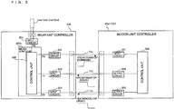
- Fig. 2 is a schematic diagram illustrating the configuration of a relay-unit controller and an indoor-unit controller according to Embodiment 1 of the present invention.
- the relay-unit controller 63b includes a control unit 300 within a microcomputer 300a, an output circuit 301, an input circuit 302, an input circuit 303, and an input circuit 304.
- Each of the indoor-unit controllers 62 includes a control unit 200, an input circuit 201, an output circuit 202, and an output circuit 203.
- the relay-unit controller 63b and each indoor-unit controller 62 are connected by three transmission lines 71.
- a transmission line 71a connects the output circuit 301 of the relay-unit controller 63b to the input circuit 201 of the indoor-unit controller 62.
- a transmission line 71b connects the input circuit 302 of the relay-unit controller 63b to the output circuit 202 of the indoor-unit controller 62.
- a transmission line 71c connects the input circuit 303 of the relay-unit controller 63b to the output circuit 203 of the indoor-unit controller 62.
- the indoor-unit controllers 62a of the indoor units have the same configuration and are each connected to the relay-unit controller 63b by three transmission lines 71. Furthermore, the number of output circuits 301, input circuits 302, and input circuits 303 provided in the relay-unit controller 63b correspond to the number of indoor-unit controllers 62 connected thereto.
- the output circuit 301 of the relay-unit controller 63b transmits a binary signal corresponding to an operation command and a stop command via the transmission line 71a in accordance with output processing from the control unit 300.
- the binary signal is, for example, an on/off signal that sets the operation command to a predetermined voltage value and the stop command to an output value of zero.
- the input circuit 201 of each indoor-unit controller 62 receives the binary signal via the transmission line 71a and inputs the binary signal to the control unit 200.
- the control unit 200 starts or stops the operation of the indoor unit 2 on the basis of the input binary signal.
- start the operation of the indoor unit 2 refers to, for example, a state (thermostat-on state) in which a fan and the like within the indoor unit 2 are driven so as to facilitate heat exchange between the heat medium and indoor air (thermal load) by the use-side heat exchanger 26.
- stop the operation refers to, for example, a state (thermostat-off state) in which the driving of the fan and the like within the indoor unit 2 is stopped so as not to facilitate heat exchange between the heat medium and indoor air (thermal load) by the use-side heat exchanger 26.
- the output circuit 202 of the indoor-unit controller 62 transmits a binary signal corresponding to an operating state and a stopped state of the indoor unit via the transmission line 71b in accordance with output processing from the control unit 200.
- This binary signal is, for example, an on/off signal that sets the operating state to a predetermined voltage value and the stopped state to an output value of zero.
- the input circuit 302 of the relay-unit controller 63b receives the binary signal via the transmission line 71b and inputs the binary signal to the control unit 300.
- the control unit 300 determines whether the indoor unit 2 is in the operating state or the stopped state on the basis of the input binary signal.
- the output circuit 203 of the indoor-unit controller 62 transmits a binary signal corresponding to a heating mode and a cooling mode of the indoor unit via the transmission line 71c in accordance with output processing from the control unit 200.
- This binary signal is, for example, an on/off signal that sets the heating mode to a predetermined voltage value and the cooling mode to an output value of zero.
- the input circuit 303 of the relay-unit controller 63b receives the binary signal via the transmission line 71c and inputs the binary signal to the control unit 300.
- the control unit 300 determines whether the indoor unit 2 is operating in the heating mode or the cooling mode on the basis of the input binary signal.
- the input circuit 304 of the relay-unit controller 63b inputs detection values of the third temperature sensors 33a to 33d and the fourth temperature sensors 34a to 34d provided in the relay unit 3 to the control unit 300.
- the control unit 300 performs a process of automatic determination of connected branch ports on the basis of input temperature data.
- the control unit 300 may be achieved by software executed on the microcomputer 300a but not limited to this.
- the control unit 300 may be achieved with hardware, such as a circuit device that achieves the function of the control unit 300.
- control unit 200 may similarly be achieved by software executed on a microcomputer.
- a relay circuit or the like may be used in place of a microcomputer.
- the relay-unit controller 63b and each indoor-unit controller 62 can exchange information by inputting and outputting binary signals (on/off signals).
- the input circuits and the output circuits can be achieved at a lower cost, as compared with the configuration in Fig. 8 , which is a related-art technology.
- the indoor-unit controllers 62 can also be achieved at a lower cost since microcomputers are not used therein.
- the indoor-unit controllers 62 may start or stop the operation of the indoor units 2 in response to commands from remote controllers or the like provided in the indoor units 2.
- the relay-unit controller 63b sets the operation mode to be executed by the refrigerating and air-conditioning apparatus 100 and switches the passages extending to the use-side heat exchangers 26 by controlling the stop valves 24, the flow switching valves 22, the flow switching valves 23, and the like so that hot water or cold water is supplied from the corresponding branch ports 6 in accordance with the binary signals corresponding to the operating/stopped states and the binary signals corresponding to the heating/cooling modes received from the indoor-unit controllers 62.
- the relay-unit controller 63b and the indoor-unit controllers 62 communicate with each other only by input and output of binary signals (on/off signals), so that limitations with respect to the communication of the indoor units 2 that can be connected to the relay unit 3 can be reduced.
- the refrigerating and air-conditioning apparatus 100 having the above configuration performs the process of automatic determination of connected branch ports in which to identify which indoor unit 2 is connected to which branch port 6 during trial operation performed after installation of the apparatus.
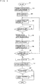
- Fig. 3 is a flowchart illustrating the flow of the process of automatic determination of connected branch ports of the indoor units in the refrigerating and air-conditioning apparatus according to Embodiment 1 of the present invention.
- the refrigerating and air-conditioning apparatus 100 commences the automatic determination process when, for example, the switch 64 provided in the relay unit 3 is operated.
- step 101 to step 113 correspond to a process performed by the relay unit 3.
- step 102 the relay unit 3 transmits a trial heating only operation command to the heat source device 1 and the process proceeds to step 103.
- step 103 the heat source device 1 receives the trial heating only operation command from the relay unit 3 and starts operating in the heating only operation mode described above.
- the relay unit 3 starts operating in the heating only operation mode and supplies hot water (heated heat medium) to all of the branch ports 6a to 6d regardless of the operation modes (heating/cooling) of the indoor units 2. Subsequently, the process proceeds to step 104.
- step 104 an operation command is transmitted to indoor units 2 to which an operation command is not transmitted yet.
- no operation command has been transmitted yet, and an operation command is transmitted to the first indoor unit 2a via the transmission line 71a so that the indoor unit 2a begins to operate.
- the process proceeds to step 105.
- the hot water and indoor air exchange heat with each other in the use-side heat exchanger 26a of the indoor unit 2a, thereby heating the indoor area or the like in which the indoor unit 2a is installed (heating mode).
- step 105 after waiting for a predetermined time to elapse, the process proceeds to step 106.
- step 106 current water-temperature data of all of the branch ports 6a to 6d are acquired.
- temperatures T33a to T33d of the four third temperature sensors 33a to 33d and temperatures T34a to T34d of the four fourth temperature sensors 34a to 34d are acquired. The process then proceeds to step 107.
- step 107 the branch-port determination process is performed. In this case, changes in the data of the temperatures T33a to T33d of the four third temperature sensors 33a to 33d and the temperatures T34a to T34d of the four fourth temperature sensors 34a to 34d are checked.
- the temperatures detected by the third temperature sensors 33a to 33d are temperatures (outlet temperatures) of hot water supplied to the use-side heat exchangers 26a to 26d from the branch ports 6a to 6d.
- the temperatures detected by the fourth temperature sensors 34a to 34d are temperatures (inlet temperatures) of hot water returning to the branch ports 6a to 6d from the use-side heat exchangers 26a to 26d.
- the temperature difference ⁇ T at the branch port 6 connected to the indoor unit 2a is a positive value.
- the temperature difference ⁇ T at each of the branch ports 6 connected to the indoor units 2b to 2d is a value whose absolute value is small.
- the relay unit 3 determines that an indoor unit 2 currently in operation is connected to the branch port 6 at which the aforementioned temperature difference ⁇ T is detected.
- the value of a temperature difference ⁇ T is a positive value smaller than the predetermined determination value or is a negative value, it is determined that an indoor unit 2 currently in a stopped state or no indoor unit 2 is connected to the branch port 6 at which the aforementioned temperature difference ⁇ T is detected.
- the relay unit 3 determines that the indoor unit 2a is connected to the branch port 6a.
- the relay unit 3 can determine which one of the branch ports 6 is connected to an indoor unit 2 currently in operation.
- the relay unit 3 determines there is a setting error.
- the relay unit 3 proceeds to step 108.
- step 108 the relay unit 3 transmits a stop command to the indoor unit 2a in operation via the transmission line 71a so as to stop the operation of the indoor unit 2a. Subsequently, the process proceeds to step 109.
- step 109 it is determined whether there are indoor units 2 to which an operation command has not been transmitted yet. If yes, the process proceeds to step 104. If no, the process proceeds to step 110.
- step 104 since an operation command has not been transmitted to the indoor units 2b to 2d yet, the process proceeds to step 104, and the same process is repeated.
- the relay unit 3 makes all of the connected indoor units 2 operate on a one-by-one basis and performs the connected-branch-port determination process for identifying which indoor unit 2 is connected to each branch port 6 on the basis of the temperature difference ⁇ T at that time.
- the relay unit 3 proceeds to step 110.
- step 110 the relay unit 3 stops the heating only operation mode and proceeds to step 111.
- step 111 a stop command is transmitted to the heat source device 1, and the process proceeds to step 112.
- step 112 if a setting error is detected during the determination process in step 107, the process proceeds to step 113. If a setting error is not detected, the process ends.
- the term "setting error” refers to a case where, for example, a connector that connects a wire extending from a temperature sensor to a substrate is not connected or is improperly connected, a connector that connects a wire extending from an actuator, such as a flow control valve, to a substrate is not connected or is improperly connected, or a normal temperature change cannot be detected during a failure in an input-output circuit.
- an abnormal-state notification process is performed by, for example, displaying an abnormal state on display means provided in a remote controller or the like or turning on an error lamp provided in the heat source device 1. Subsequently, the process ends.
- the process of automatic determination of connected branch ports shown in Fig. 3 is performed in the heating only operation mode
- the process can be performed similarly in the cooling only operation mode.
- hot water may be supplied to an indoor unit 2 and may exchange heat with the cooling load in the heating only operation mode during wintertime
- cold water may be supplied to an indoor unit 2 and may exchange heat with the heating load in the cooling only operation mode during summertime.
- the indoor units 2 are made to operate on a one-by-one basis, and it is identified which indoor unit 2 is connected to each branch port 6 on the basis of the temperature difference ⁇ T between the inlet temperature and the outlet temperature of the branch port 6 at that time.
- the interface between the relay unit 3 and each indoor unit 2 can be controlled based on simple transmission of information, which only includes the operation/stop commands, the operating/stopped states, and the heating/cooling modes.
- the interface between the relay unit 3 and each indoor unit 2 can be achieved by inexpensive transmission means.
- the communication between the relay-unit controller 63b and each indoor-unit controller 62 information can be exchanged therebetween by input and output of binary signals (on/off signals). Therefore, as compared with the configuration of the related art shown in Fig. 8 , the need for performing digital-signal conversion during a transmission process and a reception analysis process during reception can be eliminated. Consequently, the program of the microcomputer 300a in the relay-unit controller 63b is simplified, thereby reducing limitations with respect to connectable indoor units 2. Furthermore, the input-output circuits 302 and 303 can be achieved with a simple configuration at a lower cost. Moreover, the indoor-unit controllers 62 can also be achieved at a lower cost since microcomputers are not used therein.
- a determination error can be prevented in advance. Moreover, improper connections, connection leak, and defects in the connectors on the substrates in the relay-unit controller 63b and the indoor-unit controllers 62 can be detected at an early stage.
- Embodiment 2 described below the time required for the process of automatic determination of connected branch ports of the indoor units 2 is shortened.
- the process of automatic determination of connected branch ports is desirably performed within a shorter period of time.
- Embodiment 2 a refrigerating and air-conditioning apparatus is obtained that can shorten the time required for the automatic determination process, as compared with the case where the determination process is performed by making the indoor units 2 operate on a one-by-one basis.
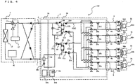
- Fig. 4 is a schematic circuit diagram illustrating the configuration of the refrigerating and air-conditioning apparatus according to Embodiment 2 of the present invention.
- Embodiment 1 The following description mainly relates to points different from Embodiment 1. Components that are the same as those in Embodiment 1 are given the same reference numerals.
- the indoor units 2 in Embodiment 2 are each provided with a ninth temperature sensor 39 and a tenth temperature sensor 40.
- the four ninth temperature sensors 39 are provided at the inlet side of the heat-medium passages of the use-side heat exchangers 26, are configured to detect the temperature of the heat medium flowing into the use-side heat exchangers 26, and may be formed of thermistors or the like.
- the number of ninth temperature sensors 39 provided corresponds to the number of (four, in this case) indoor units 2 installed.
- the ninth temperature sensor 39a, the ninth temperature sensor 39b, the ninth temperature sensor 39c, and the ninth temperature sensor 39d are shown in that order from the lower side of the drawing.
- the four tenth temperature sensors 40 are provided at the outlet side of the heat-medium passages of the use-side heat exchangers 26, are configured to detect the temperature of the heat medium flowing out of the use-side heat exchangers 26, and may be formed of thermistors or the like.
- the number of tenth temperature sensors 40 provided corresponds to the number of (four, in this case) indoor units 2 installed. In line with the indoor units 2, the tenth temperature sensor 40a, the tenth temperature sensor 40b, the tenth temperature sensor 40c, and the tenth temperature sensor 40d are shown in that order from the lower side of the drawing.
- the number of connected heat source devices 1, indoor units 2, and relay units 3 is not limited to that shown in the drawing.
- Detection values of the ninth temperature sensors 39 and the tenth temperature sensors 40 in the indoor units 2 are transmitted to the relay-unit controller 63b from the indoor-unit controllers 62 via the transmission lines 71.
- temperature data is converted into a transmittable digital signal by signal processing performed by a microcomputer provided in each indoor-unit controller 62, and the digital signal is converted into a signal waveform by a transmission circuit before being transmitted via the corresponding transmission line 71.
- the refrigerating and air-conditioning apparatus 100 having the above configuration performs the process of automatic determination of connected branch ports so as to identify which indoor unit 2 is connected to which branch port 6 during trial operation performed after installation of the apparatus.
- Fig. 5 is a flowchart illustrating the flow of the process of automatic determination of connected branch ports of the indoor units in the refrigerating and air-conditioning apparatus according to Embodiment 2 of the present invention.
- the refrigerating and air-conditioning apparatus 100 commences the automatic determination process when, for example, the switch 64 provided in the relay unit 3 is operated.
- step 201 to step 217 correspond to a process performed by the relay unit 3.
- step 202 the relay unit 3 transmits a trial heating main operation command to the heat source device 1 and proceeds to step 203.
- step 203 the heat source device 1 receives the trial heating main operation command from the relay unit 3 and starts operating in the heating main operation mode described above.
- the relay unit 3 starts operating in the heating main operation mode. In this case, all of the stop valves 24a to 24d are closed. Subsequently, the process proceeds to step 204.
- step 204 an operation command is transmitted to all of the indoor units 2a to 2d so that all of the indoor units 2 begin to operate. Subsequently, the process proceeds to step 205.
- step 205 hot water is supplied to the next branch port 6.
- the stop valve 24a corresponding to the branch port 6a is opened so as to switch the flow switching valve 22a and the flow switching valve 23a to the passage connected to the intermediate heat exchanger 15a for heating.
- hot water is supplied from the branch port 6a.
- the process proceeds to step 206.
- step 206 it is determined whether there are branch ports 6 that are not supplied with hot water or cold water yet. If yes, the process proceeds to step 207. If no, the process proceeds to step 208. In this case, since the branch ports 6b to 6d are not supplied with hot water or cold water yet, the process proceeds to step 207.
- step 207 cold water is supplied to the next branch port 6.
- the stop valve 24b corresponding to the branch port 6b is opened so as to switch the flow switching valve 22b and the flow switching valve 23b to the passage connected to the intermediate heat exchanger 15b for cooling.
- cold water is supplied from the branch port 6b.
- step 208 after waiting for a predetermined time to elapse, the process proceeds to step 209.
- step 209 current water-temperature data of all of the indoor units 2a to 2d are acquired.
- temperatures T39a to T39d of the four ninth temperature sensors 39a to 39d are acquired. Subsequently, the process proceeds to step 210.
- step 210 the branch-port determination process is performed. In this case, changes in the data of the temperatures T39a to T39d of the four ninth temperature sensors 39a to 39d are checked.
- the temperature T39a of the ninth temperature sensor 39a is substantially equal to the temperature of the hot water.
- the temperature T39b of the ninth temperature sensor 39b is substantially equal to the temperature of the cold water.
- the relay unit 3 determines that the branch port 6a is connected to the indoor unit 2 at which the aforementioned temperature T39 is detected. For example, the temperature of the hot water is detected by the first temperature sensor 31a.
- the determination of whether or not a certain temperature T39 is a value close to the temperature of the hot water is performed by determining whether or not a temperature difference between the temperature of the hot water and the temperature T39 is within a predetermined temperature range.
- the relay unit 3 determines that the branch port 6b is connected to the indoor unit 2 at which the aforementioned temperature T39 is detected. For example, the temperature of the cold water is detected by the first temperature sensor 31b. The determination of whether or not a certain temperature T39 is a value close to the temperature of the cold water is performed by determining whether or not a temperature difference between the temperature of the cold water and the temperature T39 is within a predetermined temperature range.
- the relay unit 3 determines that the indoor unit 2 at which the aforementioned temperature T39 is detected is connected to one of the remaining branch ports 6c and 6d or is not connected to any of the branch ports 6.
- the relay unit 3 can determine the indoor units 2 connected to the branch port 6a supplying hot water and the branch port 6b supplying cold water.
- the relay unit 3 determines a setting error.
- the relay unit 3 proceeds to step 211.
- step 211 the water supply to the branch ports supplying hot water and cold water is stopped. Subsequently, the process proceeds to step 212.
- step 212 it is determined whether there are branch ports 6 not supplied with hot water or cold water yet. If yes, the process proceeds to step 205. If no, the process proceeds to step 213.
- step 205 since the branch ports 6c and 6d are not supplied with hot water or cold water yet, the process proceeds to step 205, and the same process is repeated.
- the relay unit 3 performs the determination process for all of the branch ports 6 by determining the indoor units 2 connected to the branch ports 6 simultaneously and on a two-by-two basis.
- step 213 the relay unit 3 transmits a stop command to all of the indoor units 2 and proceeds to step 214.
- step 214 the relay unit 3 stops the heating main operation mode and proceeds to step 215.
- step 215 a stop command is transmitted to the heat source device 1, and the process proceeds to step 216.
- step 216 if a setting error is detected during the determination process in step 210, the process proceeds to step 217. If no setting error is detected, the process ends.
- the term "setting error” refers to a case where, for example, a connector that connects a wire extending from a temperature sensor to a substrate is not connected or is improperly connected, a connector that connects a wire extending from an actuator, such as a flow control valve, to a substrate is not connected or is improperly connected, or where a normal temperature change cannot be detected during a failure in an input-output circuit.
- an abnormal-state notification process is performed by, for example, displaying an abnormal state on display means provided in a remote controller or the like or turning on an error lamp provided in the heat source device 1. Subsequently, the process ends.
- Embodiment 2 hot water and cold water are simultaneously supplied to two branch ports 6 so that two indoor units 2 connected to these branch ports 6 are simultaneously identified on the basis of the temperatures of the heat medium flowing into the corresponding use-side heat exchangers 26.
- the time required for the automatic determination process can be shortened, as compared with the case where the branch ports 6 are determined on a one-by-one basis. Moreover, a setting error can be detected during the automatic determination process.
- Embodiment 3 described below the time required for the process of automatic determination of connected branch ports of the indoor units 2 is shortened.
- the process of automatic determination of connected branch ports is desirably performed within a shorter period of time.
- Embodiment 3 a refrigerating and air-conditioning apparatus is obtained that can shorten the time required for the automatic determination process, as compared with the case where the determination process is performed by making the indoor units 2 operate on a one-by-one basis.
- Fig. 6 is a schematic circuit diagram illustrating the configuration of the refrigerating and air-conditioning apparatus according to Embodiment 3 of the present invention.
- Embodiment 1 The following description mainly relates to points different from Embodiment 1. Components that are the same as those in Embodiment 1 are given the same reference numerals.
- the indoor units 2 in Embodiment 3 are each provided with an eleventh temperature sensor 41 and a twelfth temperature sensor 42.
- the four eleventh temperature sensors 41 are provided near air inlets of the indoor units 2, are configured to detect the temperature of indoor air, and may be formed of thermistors or the like.
- the number of eleventh temperature sensors 41 provided corresponds to the number of (four, in this case) indoor units 2 installed.
- the eleventh temperature sensor 41a, the eleventh temperature sensor 41b, the eleventh temperature sensor 41c, and the eleventh temperature sensor 41d are shown in that order from the lower side of the drawing.
- the four twelfth temperature sensors 42 are provided near air outlets of the indoor units 2, are configured to detect the temperature of discharged air, and may be formed of thermistors or the like.
- the number of twelfth temperature sensors 42 provided corresponds to the number of (four, in this case) indoor units 2 installed.
- the twelfth temperature sensor 42a, the twelfth temperature sensor 42b, the twelfth temperature sensor 42c, and the twelfth temperature sensor 42d are shown in that order from the lower side of the drawing.
- the number of connected heat source devices 1, indoor units 2, and relay units 3 is not limited to that shown in the drawing.
- Detection values of the eleventh temperature sensors 41 and the twelfth temperature sensors 42 in the indoor units 2 are transmitted to the relay-unit controller 63b from the indoor-unit controllers 62 via the transmission lines 71.
- temperature data is converted into a transmittable digital signal by signal processing performed by a microcomputer provided in each indoor-unit controller 62, and the digital signal is converted into a signal waveform by a transmission circuit and transmitted via the corresponding transmission line 71.
- the refrigerating and air-conditioning apparatus 100 having the above configuration performs the process of automatic determination of connected branch ports so as to identify which indoor unit 2 is connected to which branch port 6 during trial operation performed after installation of the apparatus.
- Fig. 7 is a flowchart illustrating the flow of the process of automatic determination of connected branch ports of the indoor units in the refrigerating and air-conditioning apparatus according to Embodiment 3 of the present invention.
- the refrigerating and air-conditioning apparatus 100 commences the automatic determination process when, for example, the switch 64 provided in the relay unit 3 is operated.
- step 301 to step 315 correspond to a process performed by the relay unit 3.
- step 302 the relay unit 3 transmits a trial heating main operation command to the heat source device 1 and proceeds to step 303.
- step 203 when the heat source device 1 receives the trial heating main operation command from the relay unit 3, it starts operating in the heating main operation mode described above.
- the relay unit 3 starts operating in the heating main operation mode. In this case, all of the stop valves 24a to 24d are opened. Subsequently, the process proceeds to step 304.
- step 304 an operation command is transmitted to all of the indoor units 2a to 2d so that all of the indoor units 2 begin to operate. Subsequently, the process proceeds to step 305.
- step 305 the amount of hot water to be supplied, the amount of cold water to be supplied, and the flow rates thereof are calculated for the individual branch ports 6.
- hot water is supplied to the first half of the branch ports 6, whereas cold water is supplied to the second half of the branch ports 6.
- hot water is supplied to the branch ports 6a and 6b, whereas cold water is supplied to the branch ports 6c and 6d.
- the flow rates are calculated with L as the number of branch ports 6 in the first half and M as the number of branch ports 6 in the second half.
- the flow rate at the branch port 6a is 50%
- the flow rate at the branch port 6b is 100%
- the flow rate at the branch port 6c is 50%
- the flow rate at the branch port 6d is 100%.
- step 306 hot water or cold water is supplied to each branch port 6 based on the calculation results obtained in step 305, and the flow rate at each branch port 6 is set.
- the flow switching valve 22a and the flow switching valve 23a corresponding to the branch port 6a are switched to the passage connected to the intermediate heat exchanger 15a for heating so that hot water is supplied from the branch port 6a. Furthermore, the opening degree of the flow control valve 25a is adjusted so that the flow rate at the branch port 6a is set to 50%.
- the flow switching valve 22b and the flow switching valve 23b corresponding to the branch port 6b are switched to the passage connected to the intermediate heat exchanger 15a for heating so that hot water is supplied from the branch port 6b. Moreover, the opening degree of the flow control valve 25b is adjusted so that the flow rate at the branch port 6b is set to 100%.
- the flow switching valve 22c and the flow switching valve 23c corresponding to the branch port 6c are switched to the passage connected to the intermediate heat exchanger 15b for cooling so that cold water is supplied from the branch port 6b. Moreover, the opening degree of the flow control valve 25c is adjusted so that the flow rate at the branch port 6c is set to 50%.
- the flow switching valve 22d and the flow switching valve 23d corresponding to the branch port 6d are switched to the passage connected to the intermediate heat exchanger 15b for cooling so that cold water is supplied from the branch port 6d. Moreover, the opening degree of the flow control valve 25d is adjusted so that the flow rate at the branch port 6b is set to 100%.
- step 307 after waiting for a predetermined time to elapse, the process proceeds to step 308.
- step 308 current suction temperature data and current discharge temperature data of all of the indoor units 2a to 2d are acquired.
- temperatures T41a to T41d of the four eleventh temperature sensors 41a to 41d and temperatures T42a to T42d of the four twelfth temperature sensors 42a to 42d are acquired. Subsequently, the process proceeds to step 309.
- step 309 the branch-port determination process is performed.
- changes in the data of the temperatures T41a to T41d of the four eleventh temperature sensors 41a to 41d and the temperatures T42a to T42d of the four twelfth temperature sensors 42a to 42d are checked.
- the temperature difference ⁇ Ta is a positive value since heat is transferred from the hot water to air at the use-side heat exchanger 26a of the indoor unit 2a.
- the temperature difference ⁇ Tb is a positive value. Because the flow rate at the branch port 6a is 50% and the flow rate at the branch port 6b is 100%, the temperature difference ⁇ Tb is a value larger than the temperature difference ⁇ Ta.
- the temperature difference ⁇ Tc is a negative value since the cold water receives heat from air at the use-side heat exchanger 26c of the indoor unit 2c.
- the temperature difference ⁇ Td is a negative value. Because the flow rate at the branch port 6c is 50% and the flow rate at the branch port 6d is 100%, the temperature difference ⁇ Td is a negative value whose absolute value is larger than that of the temperature difference ⁇ Tc.
- the relay unit 3 determines that the indoor unit 2a supplied with hot water at a flow rate of 50% is connected to the branch port 6 at which the aforementioned temperature difference ⁇ T is detected.
- a certain temperature difference ⁇ T is a positive value that is larger than the predetermined determination value, it is determined that the indoor unit 2b supplied with hot water at a flow rate of 100% is connected to the branch port 6 at which the aforementioned temperature difference ⁇ T is detected.
- a certain temperature difference ⁇ T is a negative value and the absolute value thereof is smaller than the predetermined determination value, it is determined that the indoor unit 2c supplied with cold water at a flow rate of 50% is connected to the branch port 6 at which the aforementioned temperature difference ⁇ T is detected.
- a certain temperature difference ⁇ T is a negative value and the absolute value thereof is larger than the predetermined determination value, it is determined that the indoor unit 2d supplied with cold water at a flow rate of 100% is connected to the branch port 6 at which the aforementioned temperature difference ⁇ T is detected.
- the relay unit 3 can determine the indoor units connected to the branch ports.
- the relay unit 3 determines there is a setting error.
- the relay unit 3 proceeds to step 310.
- step 310 the water supply to the branch ports supplying hot water and cold water is stopped. Subsequently, the process proceeds to step 311.
- step 311 the relay unit 3 transmits a stop command to all of the indoor units 2 and proceeds to step 312.
- step 312 the relay unit 3 stops the heating main operation mode and proceeds to step 313.
- step 313 a stop command is transmitted to the heat source device 1, and the process proceeds to step 314.
- step 314 if a setting error is detected during the determination process in step 309, the process proceeds to step 315. If a setting error is not detected, the process ends.
- the term "setting error” refers to a case where, for example, a connector that connects a wire extending from a temperature sensor to a substrate is not connected or is improperly connected, a connector that connects a wire extending from an actuator, such as a flow control valve, to a substrate is not connected or is improperly connected, or a normal temperature change cannot be detected during to a failure in an input-output circuit.
- an abnormal-state notification process is performed by, for example, displaying an abnormal state on display means provided in a remote controller or the like or turning on an error lamp provided in the heat source device 1. Subsequently, the process ends.
- Embodiment 3 hot water and cold water are simultaneously supplied to the branch ports 6, and the flow rate at each branch port 6 is adjusted, so that a plurality of indoor units 2 connected to the branch ports 6 are simultaneously identified on the basis of the temperature differences between the discharge temperatures and the suction temperatures in the indoor units 2.
- the time required for the automatic determination process can be shortened, as compared with the case where the branch ports 6 are determined on a one-by-one basis. Moreover, a setting error can be detected during the automatic determination process.
Claims (5)
- Appareil de réfrigération et de climatisation comprenant :un cycle de réfrigération qui amène un fluide frigorigène à circuler à travers celui-ci en reliant un compresseur (10), un échangeur de chaleur côté source de chaleur (12), au moins une vanne de détente (16a à 16d), et au moins un échangeur de chaleur intermédiaire (15a, 15b) ; etun circuit de milieu de chaleur qui amène un milieu de chaleur à circuler à travers celui-ci en reliant au moins une pompe (21a, 21b), une pluralité d'échangeurs de chaleur côté utilisation (26a à 26d), et ledit au moins un échangeur de chaleur intermédiaire (15a, 15b),dans lequel ledit au moins un échangeur de chaleur intermédiaire (15a, 15b) et ladite au moins une pompe (21a, 21b) sont logés dans une unité relais (3), etdans lequel la pluralité d'échangeurs de chaleur côté utilisation (26a à 26d) sont logés dans des unités intérieures (2a à 2d) respectives,dans lequel chaque unité intérieure (2a à 2d) comprend un contrôleur d'unité intérieure (62a à 62d) qui effectue une commande tout ou rien pour le fonctionnement effectué par l'échangeur de chaleur côté utilisation pour échanger la chaleur entre le milieu de chaleur et une charge thermique, etdans lequel l'unité relais (3) comprend :une pluralité d'orifices de branchement (6a à 6d) qui sont reliés à la pluralité d'échangeurs de chaleur côté utilisation (26a à 26d) et qui amènent le milieu de chaleur à circuler vers les échangeurs de chaleur côté utilisation (26a à 26d),des capteurs de température de sortie (34a à 34d) qui sont prévus pour les orifices de branchement (6a à 6d) respectifs et qui détectent chacun une température de sortie du milieu de chaleur s'écoulant hors de l'orifice de branchement (6a à 6d) vers l'échangeur de chaleur côté utilisation (26a à 26d) correspondant,des capteurs de température d'entrée (33a à 33d) qui sont prévus pour les orifices de branchement (6a à 6d) respectifs et qui détectent chacun une température d'entrée du milieu de chaleur s'écoulant dans l'orifice de branchement (6a à 6d) à partir de l'échangeur de chaleur côté utilisation (26a à 26d) correspondant, etun contrôleur d'unité relais (63b) qui est connecté aux contrôleurs d'unité intérieure (62a à 62d) par une ligne de transmission (71a à 71c) et qui commande le fonctionnement de chaque unité intérieure (2a à 2d) en transmettant une commande de fonctionnement ou une commande d'arrêt à celle-ci par l'intermédiaire de la ligne de transmission (71a à 71c),dans lequel le contrôleur d'unité relais (63b) amène les unités intérieures (2a à 2d) à fonctionner sur une base une par une et identifie laquelle des unités intérieures (2a à 2d) est reliée à l'orifice de branchement (6a à 6d) respectif sur la base d'une différence entre la température d'entrée et la température de sortie au niveau de l'orifice de branchement (6a à 6d) respectif.
- Appareil de réfrigération et de climatisation selon la revendication 1,
dans lequel, dans un état dans lequel le milieu de chaleur chauffé ou refroidi en effectuant un mode de fonctionnement de chauffage uniquement, dans lequel le milieu de chaleur est chauffé en amenant un fluide frigorigène à haute pression et haute température refoulé par le compresseur (10) à s'écouler vers l'échangeur de chaleur intermédiaire (15a, 15b), ou un mode de fonctionnement de refroidissement uniquement, dans lequel le milieu de chaleur est refroidi en amenant un fluide frigorigène à basse pression et basse température à s'écouler vers l'échangeur de chaleur intermédiaire (15a, 15b), circule vers la pluralité d'échangeurs de chaleur côté utilisation (26a à 26d),
le contrôleur d'unité relais (63b)
amène chaque unité intérieure (2a à 2d) à fonctionner sur une base une par une, acquiert la température d'entrée et la température de sortie au niveau de chaque orifice de branchement (6a à 6d), et
identifie que l'unité intérieure (2a à 2d) en fonctionnement est reliée à l'orifice de branchement (6a à 6d) au niveau duquel la différence entre la température d'entrée et la température de sortie est supérieure à une valeur prédéterminée. - Appareil de réfrigération et de climatisation selon la revendication 1 ou 2,
dans lequel, dans un état dans lequel le milieu de chaleur chauffé ou refroidi en effectuant un mode de fonctionnement de chauffage uniquement, dans lequel le milieu de chaleur est chauffé en amenant un fluide frigorigène à haute pression et haute température refoulé par le compresseur (10) à s'écouler vers l'échangeur de chaleur intermédiaire (15a, 15b), ou un mode de fonctionnement de refroidissement uniquement, dans lequel le milieu de chaleur est refroidi en amenant un fluide frigorigène à basse pression et basse température à s'écouler vers l'échangeur de chaleur intermédiaire (15a, 15b), circule vers la pluralité d'échangeurs de chaleur côté utilisation (26a à 26d),
le contrôleur d'unité relais (63b)
amène chaque unité intérieure (2a à 2d) à fonctionner sur une base une par une, acquiert la température d'entrée et la température de sortie au niveau de chaque orifice de branchement (6a à 6d), et
détermine qu'il y a une erreur de réglage si au niveau d'aucun des orifices de branchement (6a à 6d) la différence entre la température d'entrée et la température de sortie n'est supérieure à une valeur prédéterminée. - Appareil de réfrigération et de climatisation selon l'une quelconque des revendications 1 à 3,
dans lequel le contrôleur d'unité relais (63b) transmet un signal binaire correspondant à la commande de fonctionnement et à la commande d'arrêt par l'intermédiaire de la ligne de transmission (71a à 71c), et
dans lequel chaque contrôleur d'unité intérieure (62a à 62d) effectue une commande tout ou rien pour le fonctionnement de l'unité intérieure (2a à 2d) conformément au signal binaire reçu par l'intermédiaire de la ligne de transmission (71a à 71c). - Appareil de réfrigération et de climatisation selon l'une quelconque des revendications 1 à 4,
dans lequel uniquement un signal binaire est transmis par l'intermédiaire de la ligne de transmission (71a à 71c).
Applications Claiming Priority (1)
| Application Number | Priority Date | Filing Date | Title |
|---|---|---|---|
| PCT/JP2011/001174 WO2012117441A1 (fr) | 2011-03-01 | 2011-03-01 | Dispositif de réfrigération et de climatisation |
Publications (3)
| Publication Number | Publication Date |
|---|---|
| EP2682686A1 EP2682686A1 (fr) | 2014-01-08 |
| EP2682686A4 EP2682686A4 (fr) | 2014-08-13 |
| EP2682686B1 true EP2682686B1 (fr) | 2019-11-06 |
Family
ID=46757417
Family Applications (1)
| Application Number | Title | Priority Date | Filing Date |
|---|---|---|---|
| EP11860082.4A Active EP2682686B1 (fr) | 2011-03-01 | 2011-03-01 | Dispositif de réfrigération et de climatisation |
Country Status (5)
| Country | Link |
|---|---|
| US (1) | US20130305758A1 (fr) |
| EP (1) | EP2682686B1 (fr) |
| JP (1) | JP5558625B2 (fr) |
| CN (1) | CN103403464B (fr) |
| WO (1) | WO2012117441A1 (fr) |
Families Citing this family (12)
| Publication number | Priority date | Publication date | Assignee | Title |
|---|---|---|---|---|
| JP5984960B2 (ja) * | 2012-11-30 | 2016-09-06 | 三菱電機株式会社 | 空気調和装置 |
| CN103759455B (zh) * | 2014-01-27 | 2015-08-19 | 青岛海信日立空调系统有限公司 | 热回收变频多联式热泵系统及其控制方法 |
| US9823003B2 (en) * | 2014-01-30 | 2017-11-21 | Mitsubishi Electric Corporation | Air-conditioning apparatus and air-conditioning system determining valve setting error |
| JP2017090002A (ja) * | 2015-11-13 | 2017-05-25 | 株式会社コロナ | 冷温水供給システム |
| FR3055334B1 (fr) * | 2016-08-25 | 2018-08-03 | Arkema France | Copolymere a blocs porteur de groupes associatifs, son procede de preparation et ses utilisations |
| KR102572079B1 (ko) * | 2017-01-10 | 2023-08-30 | 삼성전자주식회사 | 공조 장치, 공조 장치의 제어 장치 및 공조 장치의 제어 방법 |
| GB2590862B (en) * | 2018-09-21 | 2022-05-18 | Mitsubishi Electric Corp | Air-conditioning apparatus |
| KR20200114068A (ko) | 2019-03-27 | 2020-10-07 | 엘지전자 주식회사 | 공기 조화 장치 |
| KR20200114123A (ko) * | 2019-03-27 | 2020-10-07 | 엘지전자 주식회사 | 공기조화 장치 |
| KR20200114031A (ko) | 2019-03-27 | 2020-10-07 | 엘지전자 주식회사 | 공기조화 장치 |
| KR102582538B1 (ko) * | 2019-05-17 | 2023-09-26 | 엘지전자 주식회사 | 공기 조화 장치 및 공기 조화 장치의 배관탐색방법 |
| KR20210096521A (ko) * | 2020-01-28 | 2021-08-05 | 엘지전자 주식회사 | 공기 조화 장치 |
Family Cites Families (22)
| Publication number | Priority date | Publication date | Assignee | Title |
|---|---|---|---|---|
| US4333316A (en) * | 1980-10-14 | 1982-06-08 | General Electric Company | Automatic control apparatus for a heat pump system |
| AU636215B2 (en) * | 1990-04-23 | 1993-04-22 | Mitsubishi Denki Kabushiki Kaisha | Air conditioning apparatus |
| JP3113422B2 (ja) * | 1992-11-11 | 2000-11-27 | 三洋電機株式会社 | 空気調和機のアドレス自動設定方式 |
| JP3219568B2 (ja) * | 1993-09-03 | 2001-10-15 | 三菱重工業株式会社 | 空調システムの自動アドレス制御装置 |
| JP3102239B2 (ja) * | 1993-12-21 | 2000-10-23 | 松下電器産業株式会社 | 多室空気調和機 |
| JP3259273B2 (ja) * | 1995-10-24 | 2002-02-25 | ダイキン工業株式会社 | 空気調和装置 |
| JP3152615B2 (ja) | 1996-02-26 | 2001-04-03 | 三洋電機株式会社 | 空気調和機のアドレス設定方法および接続検出方法 |
| JP3152616B2 (ja) * | 1996-02-26 | 2001-04-03 | 三洋電機株式会社 | 空気調和機のアドレス設定方法 |
| US6126080A (en) * | 1996-10-18 | 2000-10-03 | Sanyo Electric Co., Ltd. | Air conditioner |
| JP4407089B2 (ja) * | 2001-09-20 | 2010-02-03 | 株式会社富士通ゼネラル | 空気調和機の冷媒系統アドレス設定方法 |
| KR100459184B1 (ko) * | 2002-08-24 | 2004-12-03 | 엘지전자 주식회사 | 냉난방 동시형 멀티공기조화기 |
| WO2004040208A1 (fr) * | 2002-10-30 | 2004-05-13 | Mitsubishi Denki Kabushiki Kaisha | Conditionneur d'air |
| JP4211432B2 (ja) * | 2003-02-27 | 2009-01-21 | 三菱電機株式会社 | 空気調和機の冷媒中継ユニット |
| JP2006118765A (ja) * | 2004-10-20 | 2006-05-11 | Matsushita Electric Ind Co Ltd | 空気調和装置 |
| JP4794176B2 (ja) * | 2005-02-07 | 2011-10-19 | 三菱電機株式会社 | アドレス自動設定方法及びアドレス自動設定システム |
| JP2007085673A (ja) * | 2005-09-22 | 2007-04-05 | Mitsubishi Heavy Ind Ltd | 空調システムのアドレス設定方法及びプログラム |
| US9212825B2 (en) * | 2008-04-30 | 2015-12-15 | Mitsubishi Electric Corporation | Air conditioner |
| JP5247812B2 (ja) * | 2008-10-29 | 2013-07-24 | 三菱電機株式会社 | 空気調和装置 |
| CN105180497B (zh) * | 2008-10-29 | 2017-12-26 | 三菱电机株式会社 | 空气调节装置 |
| JP5474048B2 (ja) * | 2009-03-23 | 2014-04-16 | 三菱電機株式会社 | 空気調和装置 |
| US9121624B2 (en) * | 2009-03-26 | 2015-09-01 | Mitsubishi Electric Corporation | Information transfer system for refrigeration air-conditioning apparatus |
| JP5545100B2 (ja) * | 2009-08-31 | 2014-07-09 | 三洋電機株式会社 | 冷却管理装置 |
-
2011
- 2011-03-01 WO PCT/JP2011/001174 patent/WO2012117441A1/fr active Application Filing
- 2011-03-01 EP EP11860082.4A patent/EP2682686B1/fr active Active
- 2011-03-01 US US13/982,503 patent/US20130305758A1/en not_active Abandoned
- 2011-03-01 JP JP2013502038A patent/JP5558625B2/ja active Active
- 2011-03-01 CN CN201180068778.0A patent/CN103403464B/zh not_active Expired - Fee Related
Non-Patent Citations (1)
| Title |
|---|
| None * |
Also Published As
| Publication number | Publication date |
|---|---|
| WO2012117441A1 (fr) | 2012-09-07 |
| US20130305758A1 (en) | 2013-11-21 |
| CN103403464B (zh) | 2016-01-20 |
| JP5558625B2 (ja) | 2014-07-23 |
| EP2682686A4 (fr) | 2014-08-13 |
| JPWO2012117441A1 (ja) | 2014-07-07 |
| EP2682686A1 (fr) | 2014-01-08 |
| CN103403464A (zh) | 2013-11-20 |
Similar Documents
| Publication | Publication Date | Title |
|---|---|---|
| EP2682686B1 (fr) | Dispositif de réfrigération et de climatisation | |
| EP1371914B1 (fr) | Dispositif de climatisation a unités multiples et méthode de régulation pour celui-ci | |
| US8844302B2 (en) | Air-conditioning apparatus | |
| EP2413055B1 (fr) | Climatiseur | |
| EP3279580B1 (fr) | Dispositif de climatisation | |
| US9285128B2 (en) | Air-conditioning apparatus with multiple outdoor, indoor, and multiple relay units | |
| US20140033749A1 (en) | Multi air-conditioning apparatus | |
| US10077930B2 (en) | Air-conditioning apparatus and air-conditioning system | |
| EP1643193B1 (fr) | Méthode pour la détermination de configuration d'un système de conditionnement d'air | |
| KR101195557B1 (ko) | 공기 조화기의 검사 방법 | |
| JP2014173816A (ja) | マルチ型空気調和機 | |
| KR101116211B1 (ko) | 멀티 에어컨 시스템 및 멀티 에어컨 시스템의 배관연결탐색방법 | |
| KR101204443B1 (ko) | 멀티형 공기조화기 및 그 제어방법 | |
| JPH0311256A (ja) | マルチ形空気調和機 | |
| WO2024018987A1 (fr) | Dispositif de climatisation | |
| KR20050122624A (ko) | 멀티 에어컨 시스템 및 배관탐색방법 | |
| KR20100019162A (ko) | 멀티형 공기조화기 | |
| JPH076665B2 (ja) | 空気調和装置の運転制御装置 | |
| JP2013079736A (ja) | 多室形空気調和装置 | |
| JP2006125663A (ja) | 空気調和装置 |
Legal Events
| Date | Code | Title | Description |
|---|---|---|---|
| PUAI | Public reference made under article 153(3) epc to a published international application that has entered the european phase |
Free format text: ORIGINAL CODE: 0009012 |
|
| 17P | Request for examination filed |
Effective date: 20130802 |
|
| AK | Designated contracting states |
Kind code of ref document: A1 Designated state(s): AL AT BE BG CH CY CZ DE DK EE ES FI FR GB GR HR HU IE IS IT LI LT LU LV MC MK MT NL NO PL PT RO RS SE SI SK SM TR |
|
| DAX | Request for extension of the european patent (deleted) | ||
| A4 | Supplementary search report drawn up and despatched |
Effective date: 20140715 |
|
| RIC1 | Information provided on ipc code assigned before grant |
Ipc: F25B 49/02 20060101ALI20140709BHEP Ipc: F24F 11/02 20060101AFI20140709BHEP Ipc: F25B 25/00 20060101ALI20140709BHEP Ipc: F25B 13/00 20060101ALI20140709BHEP Ipc: F24F 1/32 20110101ALI20140709BHEP |
|
| REG | Reference to a national code |
Ref country code: DE Ref legal event code: R079 Ref document number: 602011063289 Country of ref document: DE Free format text: PREVIOUS MAIN CLASS: F24F0011020000 Ipc: F24F0001320000 |
|
| GRAP | Despatch of communication of intention to grant a patent |
Free format text: ORIGINAL CODE: EPIDOSNIGR1 |
|
| STAA | Information on the status of an ep patent application or granted ep patent |
Free format text: STATUS: GRANT OF PATENT IS INTENDED |
|
| RIC1 | Information provided on ipc code assigned before grant |
Ipc: F24F 1/32 20110101AFI20190417BHEP Ipc: F25B 49/00 20060101ALI20190417BHEP Ipc: F25B 13/00 20060101ALI20190417BHEP Ipc: F25B 25/00 20060101ALI20190417BHEP |
|
| INTG | Intention to grant announced |
Effective date: 20190520 |
|
| GRAS | Grant fee paid |
Free format text: ORIGINAL CODE: EPIDOSNIGR3 |
|
| GRAA | (expected) grant |
Free format text: ORIGINAL CODE: 0009210 |
|
| STAA | Information on the status of an ep patent application or granted ep patent |
Free format text: STATUS: THE PATENT HAS BEEN GRANTED |
|
| AK | Designated contracting states |
Kind code of ref document: B1 Designated state(s): AL AT BE BG CH CY CZ DE DK EE ES FI FR GB GR HR HU IE IS IT LI LT LU LV MC MK MT NL NO PL PT RO RS SE SI SK SM TR |
|
| REG | Reference to a national code |
Ref country code: GB Ref legal event code: FG4D |
|
| REG | Reference to a national code |
Ref country code: CH Ref legal event code: EP Ref country code: AT Ref legal event code: REF Ref document number: 1199257 Country of ref document: AT Kind code of ref document: T Effective date: 20191115 |
|
| REG | Reference to a national code |
Ref country code: IE Ref legal event code: FG4D |
|
| REG | Reference to a national code |
Ref country code: DE Ref legal event code: R096 Ref document number: 602011063289 Country of ref document: DE |
|
| REG | Reference to a national code |
Ref country code: NL Ref legal event code: MP Effective date: 20191106 |
|
| REG | Reference to a national code |
Ref country code: LT Ref legal event code: MG4D |
|
| PG25 | Lapsed in a contracting state [announced via postgrant information from national office to epo] |
Ref country code: NO Free format text: LAPSE BECAUSE OF FAILURE TO SUBMIT A TRANSLATION OF THE DESCRIPTION OR TO PAY THE FEE WITHIN THE PRESCRIBED TIME-LIMIT Effective date: 20200206 Ref country code: LT Free format text: LAPSE BECAUSE OF FAILURE TO SUBMIT A TRANSLATION OF THE DESCRIPTION OR TO PAY THE FEE WITHIN THE PRESCRIBED TIME-LIMIT Effective date: 20191106 Ref country code: FI Free format text: LAPSE BECAUSE OF FAILURE TO SUBMIT A TRANSLATION OF THE DESCRIPTION OR TO PAY THE FEE WITHIN THE PRESCRIBED TIME-LIMIT Effective date: 20191106 Ref country code: BG Free format text: LAPSE BECAUSE OF FAILURE TO SUBMIT A TRANSLATION OF THE DESCRIPTION OR TO PAY THE FEE WITHIN THE PRESCRIBED TIME-LIMIT Effective date: 20200206 Ref country code: NL Free format text: LAPSE BECAUSE OF FAILURE TO SUBMIT A TRANSLATION OF THE DESCRIPTION OR TO PAY THE FEE WITHIN THE PRESCRIBED TIME-LIMIT Effective date: 20191106 Ref country code: LV Free format text: LAPSE BECAUSE OF FAILURE TO SUBMIT A TRANSLATION OF THE DESCRIPTION OR TO PAY THE FEE WITHIN THE PRESCRIBED TIME-LIMIT Effective date: 20191106 Ref country code: SE Free format text: LAPSE BECAUSE OF FAILURE TO SUBMIT A TRANSLATION OF THE DESCRIPTION OR TO PAY THE FEE WITHIN THE PRESCRIBED TIME-LIMIT Effective date: 20191106 Ref country code: GR Free format text: LAPSE BECAUSE OF FAILURE TO SUBMIT A TRANSLATION OF THE DESCRIPTION OR TO PAY THE FEE WITHIN THE PRESCRIBED TIME-LIMIT Effective date: 20200207 Ref country code: PL Free format text: LAPSE BECAUSE OF FAILURE TO SUBMIT A TRANSLATION OF THE DESCRIPTION OR TO PAY THE FEE WITHIN THE PRESCRIBED TIME-LIMIT Effective date: 20191106 Ref country code: PT Free format text: LAPSE BECAUSE OF FAILURE TO SUBMIT A TRANSLATION OF THE DESCRIPTION OR TO PAY THE FEE WITHIN THE PRESCRIBED TIME-LIMIT Effective date: 20200306 Ref country code: ES Free format text: LAPSE BECAUSE OF FAILURE TO SUBMIT A TRANSLATION OF THE DESCRIPTION OR TO PAY THE FEE WITHIN THE PRESCRIBED TIME-LIMIT Effective date: 20191106 |
|
| PG25 | Lapsed in a contracting state [announced via postgrant information from national office to epo] |
Ref country code: RS Free format text: LAPSE BECAUSE OF FAILURE TO SUBMIT A TRANSLATION OF THE DESCRIPTION OR TO PAY THE FEE WITHIN THE PRESCRIBED TIME-LIMIT Effective date: 20191106 Ref country code: HR Free format text: LAPSE BECAUSE OF FAILURE TO SUBMIT A TRANSLATION OF THE DESCRIPTION OR TO PAY THE FEE WITHIN THE PRESCRIBED TIME-LIMIT Effective date: 20191106 Ref country code: IS Free format text: LAPSE BECAUSE OF FAILURE TO SUBMIT A TRANSLATION OF THE DESCRIPTION OR TO PAY THE FEE WITHIN THE PRESCRIBED TIME-LIMIT Effective date: 20200306 |
|
| PG25 | Lapsed in a contracting state [announced via postgrant information from national office to epo] |
Ref country code: AL Free format text: LAPSE BECAUSE OF FAILURE TO SUBMIT A TRANSLATION OF THE DESCRIPTION OR TO PAY THE FEE WITHIN THE PRESCRIBED TIME-LIMIT Effective date: 20191106 |
|
| PG25 | Lapsed in a contracting state [announced via postgrant information from national office to epo] |
Ref country code: DK Free format text: LAPSE BECAUSE OF FAILURE TO SUBMIT A TRANSLATION OF THE DESCRIPTION OR TO PAY THE FEE WITHIN THE PRESCRIBED TIME-LIMIT Effective date: 20191106 Ref country code: EE Free format text: LAPSE BECAUSE OF FAILURE TO SUBMIT A TRANSLATION OF THE DESCRIPTION OR TO PAY THE FEE WITHIN THE PRESCRIBED TIME-LIMIT Effective date: 20191106 Ref country code: RO Free format text: LAPSE BECAUSE OF FAILURE TO SUBMIT A TRANSLATION OF THE DESCRIPTION OR TO PAY THE FEE WITHIN THE PRESCRIBED TIME-LIMIT Effective date: 20191106 Ref country code: CZ Free format text: LAPSE BECAUSE OF FAILURE TO SUBMIT A TRANSLATION OF THE DESCRIPTION OR TO PAY THE FEE WITHIN THE PRESCRIBED TIME-LIMIT Effective date: 20191106 |
|
| REG | Reference to a national code |
Ref country code: DE Ref legal event code: R097 Ref document number: 602011063289 Country of ref document: DE |
|
| REG | Reference to a national code |
Ref country code: AT Ref legal event code: MK05 Ref document number: 1199257 Country of ref document: AT Kind code of ref document: T Effective date: 20191106 |
|
| PG25 | Lapsed in a contracting state [announced via postgrant information from national office to epo] |
Ref country code: SK Free format text: LAPSE BECAUSE OF FAILURE TO SUBMIT A TRANSLATION OF THE DESCRIPTION OR TO PAY THE FEE WITHIN THE PRESCRIBED TIME-LIMIT Effective date: 20191106 Ref country code: SM Free format text: LAPSE BECAUSE OF FAILURE TO SUBMIT A TRANSLATION OF THE DESCRIPTION OR TO PAY THE FEE WITHIN THE PRESCRIBED TIME-LIMIT Effective date: 20191106 |
|
| PLBE | No opposition filed within time limit |
Free format text: ORIGINAL CODE: 0009261 |
|
| STAA | Information on the status of an ep patent application or granted ep patent |
Free format text: STATUS: NO OPPOSITION FILED WITHIN TIME LIMIT |
|
| 26N | No opposition filed |
Effective date: 20200807 |
|
| PG25 | Lapsed in a contracting state [announced via postgrant information from national office to epo] |
Ref country code: MC Free format text: LAPSE BECAUSE OF FAILURE TO SUBMIT A TRANSLATION OF THE DESCRIPTION OR TO PAY THE FEE WITHIN THE PRESCRIBED TIME-LIMIT Effective date: 20191106 |
|
| REG | Reference to a national code |
Ref country code: CH Ref legal event code: PL |
|
| PG25 | Lapsed in a contracting state [announced via postgrant information from national office to epo] |
Ref country code: AT Free format text: LAPSE BECAUSE OF FAILURE TO SUBMIT A TRANSLATION OF THE DESCRIPTION OR TO PAY THE FEE WITHIN THE PRESCRIBED TIME-LIMIT Effective date: 20191106 Ref country code: SI Free format text: LAPSE BECAUSE OF FAILURE TO SUBMIT A TRANSLATION OF THE DESCRIPTION OR TO PAY THE FEE WITHIN THE PRESCRIBED TIME-LIMIT Effective date: 20191106 |
|
| REG | Reference to a national code |
Ref country code: BE Ref legal event code: MM Effective date: 20200331 |
|
| PG25 | Lapsed in a contracting state [announced via postgrant information from national office to epo] |
Ref country code: LU Free format text: LAPSE BECAUSE OF NON-PAYMENT OF DUE FEES Effective date: 20200301 |
|
| PG25 | Lapsed in a contracting state [announced via postgrant information from national office to epo] |
Ref country code: IE Free format text: LAPSE BECAUSE OF NON-PAYMENT OF DUE FEES Effective date: 20200301 Ref country code: IT Free format text: LAPSE BECAUSE OF FAILURE TO SUBMIT A TRANSLATION OF THE DESCRIPTION OR TO PAY THE FEE WITHIN THE PRESCRIBED TIME-LIMIT Effective date: 20191106 Ref country code: LI Free format text: LAPSE BECAUSE OF NON-PAYMENT OF DUE FEES Effective date: 20200331 Ref country code: CH Free format text: LAPSE BECAUSE OF NON-PAYMENT OF DUE FEES Effective date: 20200331 |
|
| PG25 | Lapsed in a contracting state [announced via postgrant information from national office to epo] |
Ref country code: BE Free format text: LAPSE BECAUSE OF NON-PAYMENT OF DUE FEES Effective date: 20200331 |
|
| PG25 | Lapsed in a contracting state [announced via postgrant information from national office to epo] |
Ref country code: TR Free format text: LAPSE BECAUSE OF FAILURE TO SUBMIT A TRANSLATION OF THE DESCRIPTION OR TO PAY THE FEE WITHIN THE PRESCRIBED TIME-LIMIT Effective date: 20191106 Ref country code: MT Free format text: LAPSE BECAUSE OF FAILURE TO SUBMIT A TRANSLATION OF THE DESCRIPTION OR TO PAY THE FEE WITHIN THE PRESCRIBED TIME-LIMIT Effective date: 20191106 Ref country code: CY Free format text: LAPSE BECAUSE OF FAILURE TO SUBMIT A TRANSLATION OF THE DESCRIPTION OR TO PAY THE FEE WITHIN THE PRESCRIBED TIME-LIMIT Effective date: 20191106 |
|
| PG25 | Lapsed in a contracting state [announced via postgrant information from national office to epo] |
Ref country code: MK Free format text: LAPSE BECAUSE OF FAILURE TO SUBMIT A TRANSLATION OF THE DESCRIPTION OR TO PAY THE FEE WITHIN THE PRESCRIBED TIME-LIMIT Effective date: 20191106 |
|
| PG25 | Lapsed in a contracting state [announced via postgrant information from national office to epo] |
Ref country code: FR Free format text: LAPSE BECAUSE OF NON-PAYMENT OF DUE FEES Effective date: 20200331 |
|
| REG | Reference to a national code |
Ref country code: DE Ref legal event code: R084 Ref document number: 602011063289 Country of ref document: DE |
|
| REG | Reference to a national code |
Ref country code: GB Ref legal event code: 746 Effective date: 20221230 |
|
| P01 | Opt-out of the competence of the unified patent court (upc) registered |
Effective date: 20230512 |
|
| PGFP | Annual fee paid to national office [announced via postgrant information from national office to epo] |
Ref country code: DE Payment date: 20240130 Year of fee payment: 14 Ref country code: GB Payment date: 20240201 Year of fee payment: 14 |