EP2682615A1 - Mutter - Google Patents
Mutter Download PDFInfo
- Publication number
- EP2682615A1 EP2682615A1 EP20120174826 EP12174826A EP2682615A1 EP 2682615 A1 EP2682615 A1 EP 2682615A1 EP 20120174826 EP20120174826 EP 20120174826 EP 12174826 A EP12174826 A EP 12174826A EP 2682615 A1 EP2682615 A1 EP 2682615A1
- Authority
- EP
- European Patent Office
- Prior art keywords
- nut
- retaining ring
- screw
- head part
- hole
- Prior art date
- Legal status (The legal status is an assumption and is not a legal conclusion. Google has not performed a legal analysis and makes no representation as to the accuracy of the status listed.)
- Granted
Links
Images


Classifications
-
- F—MECHANICAL ENGINEERING; LIGHTING; HEATING; WEAPONS; BLASTING
- F16—ENGINEERING ELEMENTS AND UNITS; GENERAL MEASURES FOR PRODUCING AND MAINTAINING EFFECTIVE FUNCTIONING OF MACHINES OR INSTALLATIONS; THERMAL INSULATION IN GENERAL
- F16B—DEVICES FOR FASTENING OR SECURING CONSTRUCTIONAL ELEMENTS OR MACHINE PARTS TOGETHER, e.g. NAILS, BOLTS, CIRCLIPS, CLAMPS, CLIPS OR WEDGES; JOINTS OR JOINTING
- F16B37/00—Nuts or like thread-engaging members
- F16B37/005—Nuts or like thread-engaging members into which threads are cut during screwing
-
- F—MECHANICAL ENGINEERING; LIGHTING; HEATING; WEAPONS; BLASTING
- F16—ENGINEERING ELEMENTS AND UNITS; GENERAL MEASURES FOR PRODUCING AND MAINTAINING EFFECTIVE FUNCTIONING OF MACHINES OR INSTALLATIONS; THERMAL INSULATION IN GENERAL
- F16B—DEVICES FOR FASTENING OR SECURING CONSTRUCTIONAL ELEMENTS OR MACHINE PARTS TOGETHER, e.g. NAILS, BOLTS, CIRCLIPS, CLAMPS, CLIPS OR WEDGES; JOINTS OR JOINTING
- F16B41/00—Measures against loss of bolts, nuts, or pins; Measures against unauthorised operation of bolts, nuts or pins
- F16B41/002—Measures against loss of bolts, nuts or pins
Definitions
- the invention relates to a nut, in particular welding, punching or rivet nut with a head part and a molded onto the head part shaft part, wherein the head part and the shaft part are penetrated by a through hole.
- Nuts in particular welding nuts of the aforementioned type are used for example in vehicle construction to attach airbag cushion to body parts.
- the weld nuts which are regularly provided with an internal thread, welded to the body parts.
- the inflatable airbag cushion is subsequently fixed by means of screws at several points of the body. When screwing the screw into the weld nut creates a traction, whereby the airbag cushion is held securely to the body.
- the installation of the airbag cushion takes place in several operations. For this purpose, it is necessary to fix the respective fastening screw initially only within the mother. So that the screw does not fall out during transport before final assembly in subsequent work steps, the screw must be held captive in the nut. For this purpose, a plastic element is applied to the screw, which can be inserted into the mother, which is held by force or positive locking the screw inside the nut.
- the invention aims to remedy this situation.
- the following invention is based on the object to provide a nut, in particular welding, punching or rivet nut, which avoids the aforementioned disadvantages and in which a captive mounting a screw without an applied to this Plastic element is enabled. According to the invention, this object is solved by the features of the characterizing part of patent claim 1.
- a mother is provided which avoids the aforementioned disadvantages and is made possible by the captive fixation of a screw without applied plastic element.
- the fixation of the screw is made possible, without this end to be provided with a plastic element.
- the holding element is formed by a hollow cylindrical retaining ring, on the inner wall at least partially an elastic projection is formed, whereby in this area a T-shaped cross-section is formed.
- the elastic projection allows the insertion of a screw which is held captive by the restoring forces of the projection.
- the retaining ring is made of plastic.
- the retaining ring may also be made of sheet metal, for example in the form of a perforated sheet steel plate provided with a breakthrough, which allows insertion of a screw. It is essential to the invention that the screw can be introduced into the screwed-in position like a plug-in connection into the welding nut provided with a retaining ring, without a screw-in procedure already taking place.
- the retaining ring is at least partially held over a crimping edge in the receptacle.
- the assembly of the retaining ring in the head part of the welding nut is simplified.
- the flanged edge is merely beaded by mechanical action.
- such a fixation can also be achieved by introducing notches in the outer edge of the receptacle, wherein the material displaced thereby causes a partial reduction of the diameter, which in turn keeps the holding element axially in the head part.
- the through hole is formed without internal thread.
- a thread-forming screw is used, which forms its counter thread itself when screwing.
- the operation of threading deleted, whereby the manufacturing cost of the mother is reduced.
- the clamping effect is increased by introducing a thread-forming screw. Since the cut mating thread is formed tolerance and form-fitting, the screw receives a self-locking.
- the molded thread can be fitted in case of repair with a metric screw.
- Another effect of using a threadless nut is that better alignment of the screw is achievable, reducing the risk of cross threading.
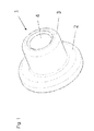
- the selected as an embodiment nut is designed as a weld nut 1 and consists essentially of a head part 2 and an integrally formed on the head part 2 shaft part 3, wherein the head part 2 and shaft part 3 are penetrated by a through hole 4.
- a retaining ring 5 for captive fixation of a screw 6 is introduced.
- the head part 2 is formed substantially hollow cylindrical and formed on the likewise substantially hollow cylindrical shaft part 3, which projects beyond it circumferentially.
- the head part 2 and the shaft part 3 have an identical outer contour, which may be formed both circular and polygonal.
- annular welding foot 21 On its underside opposite the shaft part 3, an annular welding foot 21 with a triangular cross-section is formed concentrically on the head part 2, concentric with the through-bore 4.
- the welding foot 21 serves to fasten the nut to a body panel by means of welding.
- a diameter enlarged relative to the through hole 4 receptacle 22 for the retaining ring 5 is introduced.
- the receptacle 22 is formed in the manner of a stepped bore, whereby a stop 23 is formed for the retaining ring 5.
- the receptacle 22 merges via a conical shoulder 24 into the diameter-reduced through-hole 4.
- the retaining ring 5 is made in the embodiment of plastic. It consists essentially of a hollow cylindrical shell 51, on the inner wall centrally circumferentially a web 52 is integrally formed. The web 52 has a tapered to the center of the retaining ring 5, triangular cross-section.
- the retaining ring 5 is not shown - introduced into the outer edge 221 of the receptacle 22 notches, which - not shown - material protrusions are formed in the receptacle 22 held axially.
- FIG. 6 a captive fixation according to the invention of a screw in the welding nut is shown schematically.
- the threaded pin of a screw 6 is inserted with its free end through the retaining ring 5, whereby the web 52 of the retaining ring 5 is elastically deformed and hineinformt by the elastic restoring forces in the thread 61 of the screw 6.
- the screw 6 is held in the retaining ring 5 in the manner of a connector, wherein they the cone-shaped shoulder 24 axially centered to the through hole 4 is present.
- the through hole 4 is executed without threads and there is a thread-forming screw according to DIN ISO 7085 with metric thread used. In this case, the thread is introduced into the through hole 4 in the course of screwing the screw 6.
Landscapes
- Engineering & Computer Science (AREA)
- General Engineering & Computer Science (AREA)
- Mechanical Engineering (AREA)
- Connection Of Plates (AREA)
- Dowels (AREA)
Abstract
Description
- Die Erfindung betrifft eine Mutter, insbesondere Schweiß-, Stanz- oder Nietmutter mit einem Kopfteil und einem an dem Kopfteil angeformten Schaftteil, wobei Kopfteil und Schaftteil von einer Durchgangsbohrung durchdrungen sind.
- Muttern, insbesondere Schweißmuttern der vorgenannten Art werden beispielsweise im Fahrzeugbau eingesetzt, um Airbag-Kissen an Karosserieteilen zu befestigen. Dazu werden die Schweißmuttern, die regelmäßig mit einem Innengewinde versehen sind, an die Karosserieteile angeschweißt. Das aufblasbare Airbag-Kissen wird nachfolgend mittels Schrauben an mehreren Punkten der Karosserie fixiert. Beim Eindrehen der Schraube in die Schweißmutter entsteht ein Kraftschluss, wodurch das Airbag-Kissen sicher an der Karosserie gehalten ist.
- Die Montage des Airbag-Kissens erfolgt in mehreren Arbeitsgängen. Hierzu ist es erforderlich, die jeweilige Befestigungsschraube zunächst nur innerhalb der Mutter zu fixieren. Damit die Schraube vor der endgültigen Montage in nachfolgenden Arbeitsschritten nicht während des Transports herausfällt, muss die Schraube unverlierbar in der Mutter gehalten werden. Hierzu wird auf die Schraube ein Kunststoffelement aufgebracht, welches in die Mutter eingesteckt werden kann, wodurch über Kraft- oder Formschluss die Schraube innerhalb der Mutter gehalten ist.
- Die Herstellung und Anbringung des Kunststoffelements auf die Schrauben gestaltet sich jedoch als sehr aufwendig. Weiterhin wird die Schraube durch das aufgebrachte Kunststoffelement verlängert, wodurch der Einbauraum erhöht ist.
- Hier will die Erfindung Abhilfe schaffen. Der folgenden Erfindung liegt die Aufgabe zu Grunde, eine Mutter, insbesondere Schweiß-, Stanz- oder Nietmutter zu schaffen, welche die vorgenannten Nachteile vermeidet und bei der eine unverlierbare Halterung einer Schraube ohne ein auf diese aufgebrachtes Kunststoffelement ermöglicht ist. Gemäß der Erfindung wird diese Aufgabe durch die Merkmale des kennzeichnenden Teils des Patentanspruchs 1 gelöst.
- Mit der Erfindung ist eine Mutter geschaffen, welche die vorgenannten Nachteile vermeidet und durch die eine unverlierbare Fixierung einer Schraube ohne aufgebrachtes Kunststoffelement ermöglicht ist. Durch das in das Kopfteil integrierte Halteelement ist die Fixierung der Schraube ermöglicht, ohne dass diese endseitig mit einem Kunststoffelement zu versehen ist.
- In Weiterbildung der Erfindung ist das Halteelement durch einen hohlzylinderisch ausgebildeten Haltering gebildet, an dessen Innenwandung zumindest bereichsweise ein elastischer Vorsprung angeformt ist, wodurch in diesem Bereich ein T-förmiger Querschnitt gebildet ist. Der elastische Vorsprung ermöglicht das Einstecken einer Schraube, welche durch die Rückstellkräfte des Vorsprungs unverlierbar gehalten ist. Bevorzugt ist der Haltering aus Kunststoff ausgebildet.
- Alternativ kann der Haltering jedoch auch aus Metallblech, beispielsweise auch in Form einer mit einer Durchbruch versehenen Stahlblechscheibe hergestellt sein, welche durch elastische Deformation ein Einstecken einer Schraube ermöglicht. Erfindungswesentlich ist, dass die Schraube wie eine Steckverbindung in die mit einem Haltering versehene Schweißmutter in Einschraubposition eingebracht werden kann, ohne das bereits ein Einschraubvorgang erfolgt.
- In weiterer Ausgestaltung der Erfindung ist der Haltering zumindest bereichsweise über eine Bördelkante in der Aufnahme gehalten. Hierdurch ist die Montage des Halterings in dem Kopfteil der Schweißmutter vereinfacht. Nach der Positionierung des Halterings in dem Kopfteil ist die Bördelkante lediglich durch mechanische Einwirkung umzubördeln. Alternativ kann eine solche Fixierung auch durch Einbringen von Kerben in den äußeren Rand der Aufnahme erzielt werden, wobei das dabei verdrängte Material eine partielle Verringerung des Durchmesser bewirkt, wodurch wiederum das Halteelement axial in dem Kopfteil gehalten ist.
- In Weiterbildung der Erfindung ist die Durchgangsbohrung ohne Innengewinde ausgebildet. In diesem Fall kommt eine gewindefurchende Schraube zum Einsatz, welche beim Einschrauben ihr Gegengewinde selbst formt. Der Arbeitsgang des Gewindeschneidens entfällt, wodurch der Herstellungsaufwand der Mutter reduziert ist. Zudem wird durch Einbringen einer gewindefurchenden Schraube die Klemmwirkung erhöht. Da das eingeschnittene Gegengewinde toleranz- und formschlüssig geformt wird, erhält die Schraube eine Selbsthemmung. Das geformte Gewinde kann im Reparaturfall mit einer metrischen Schraube bestückt werden. Ein weiterer Effekt des Einsatzes einer gewindelosen Mutter ist, dass eine bessere Ausrichtung der Schraube erzielbar ist, wodurch das Risiko eines "cross threading" reduziert ist.
- Andere Weiterbildungen und Ausgestaltungen der Erfindung sind in den übrigen Unteransprüchen angegeben. Ein Ausführungsbeispiel der Erfindung ist in den Zeichnungen dargestellt und wird nachfolgend im Einzelnen beschrieben. Es zeigen:
- Figur 1
- die räumliche Darstellung einer Schweißmutter;
- Figur 2
- die Schweißmutter aus
Figur 1 in der Seitenansicht; - Figur 3
- die Darstellung der Schweißmutter aus
Figur 1 im Längsschnitt; - Figur 4
- die Schweißmutter aus
Figur 1 in der Draufsicht; - Figur 5
- die Schweißmutter aus
Figur 1 in der Ansicht von unten und - Figur 6
- die schematische Darstellung einer Schweißmutter mit unverlierbar fixierter Schraube.
- Die als Ausführungsbeispiel gewählte Mutter ist als Schweißmutter 1 ausgeführt und besteht im Wesentlichen aus einem Kopfteil 2 und einem an dem Kopfteil 2 angeformten Schaftteil 3, wobei Kopfteil 2 und Schaftteil 3 von einer Durchgangsbohrung 4 durchdrungen sind. In dem Kopfteil 2 ist ein Haltering 5 zur unverlierbaren Fixierung einer Schraube 6 eingebracht.
- Das Kopfteil 2 ist im Wesentlichen hohlzylindrisch ausgebildet und an das ebenfalls im Wesentlichen hohlzylindrisch ausgebildete Schaftteil 3 angeformt, welches es umlaufend überragt. Selbstverständlich sind auch Ausgestaltungen einer Mutter möglich, bei der das Kopfteil 2 und das Schaftteil 3 eine identische Außenkontur aufweisen, welche sowohl kreisrund als auch polygonförmig ausgebildet sein kann.
- An seiner dem Schaftteil 3 entgegengesetzten Unterseite ist auf dem Kopfteil 2 konzentrisch zur Durchgangsbohrung 4 ein kreisringförmiger Schweißfuß 21 mit dreieckförmigen Querschnitt angeformt. Der Schweißfuß 21 dient der Befestigung der Mutter an einem Karosserieblech mittels Schweißen. Weiterhin ist konzentrisch zur Durchgangsbohrung 4 in das Kopfteil 2 eine gegenüber der Durchgangsbohrung 4 durchmesservergrößerte Aufnahme 22 für den Haltering 5 eingebracht. Die Aufnahme 22 ist in Art einer Stufenbohrung ausgebildet, wodurch ein Anschlag 23 für den Haltering 5 gebildet ist. Die Aufnahme 22 geht über einen kegelförmigen Absatz 24 in die durchmesserreduzierte Durchgangsbohrung 4 über.
- Der Haltering 5 ist im Ausführungsbeispiel aus Kunststoff hergestellt. Er besteht im Wesentlichen aus einem hohlzylinderförmigen Mantel 51, an dessen Innenwandung mittig umlaufend ein Steg 52 angeformt ist. Der Steg 52 weist einen sich zum Mittelpunkt des Halterings 5 verjüngenden, dreieckförmigen Querschnitt auf. Der Haltering 5 ist durch - nicht dargestellte - in die Außenkante 221 der Aufnahme 22 eingebrachte Einkerbungen, wodurch - nicht dargestellte - Materialvorsprünge gebildet sind, in der Aufnahme 22 axial gehalten.
- In
Figur 6 ist eine erfindungsgemäße unverlierbare Fixierung einer Schraube in der Schweißmutter schematisch dargestellt. Der Gewindezapfen einer Schraube 6 wird mit seinem freien Ende durch den Haltering 5 gesteckt, wodurch der Steg 52 des Halterings 5 elastisch verformt wird und sich durch die elastischen Rückstellkräfte in den Gewindegang 61 der Schraube 6 hineinformt. Auf diese Weise ist die Schraube 6 in dem Haltering 5 in Art einer Steckverbindung gehalten, wobei sie an dem kegelförmigen Absatz 24 axial zentriert zur Durchgangsbohrung 4 anliegt. Nach endgültiger Positionierung eines Airbag-Kissens kann dieses durch Anziehen der bereits ausgerichteten Schraube befestigt werden. Im Ausführungsbeispiel ist die Durchgangsbohrung 4 gewindelos ausgeführt und es kommt eine gewindefurchende Schraube nach DIN ISO 7085 mit metrischem Gewinde zum Einsatz. Dabei wird im Zuge des Einschraubvorgangs der Schraube 6 das Gewinde in die Durchgangsbohrung 4 eingebracht.
Claims (6)
- Mutter, insbesondere Schweiß-, Stanz- oder Nietmutter, mit einem Kopfteil (2) und einem an dem Kopfteil (2) angeformten Schaftteil (3), wobei Kopfteil (2) und Schaftteil (3) von einer Durchgangsbohrung (4) durchdrungen sind, dadurch gekennzeichnet, dass die Durchgangsbohrung (4) im Bereich des Kopfteils (2) zumindest bereichsweise durchmesservergrößert ausgebildet ist, wodurch eine Aufnahme (22) gebildet ist, in die ein Halteelement zur unverlierbaren Fixierung eines Schraubenendes eingebracht ist.
- Mutter nach Anspruch 1, dadurch gekennzeichnet, dass das Halteelement durch einen hohlzylindrisch ausgebildeten Haltering (5) gebildet ist, an dessen Innenwandung zumindest bereichsweise ein elastischer Vorsprung angeformt ist, wodurch in diesem Bereich ein T-förmiger Querschnitt gebildet ist.
- Mutter nach Anspruch 2, dadurch gekennzeichnet, dass der Haltering (5) aus Kunststoff ausgebildet ist.
- Mutter nach Anspruch 2, dadurch gekennzeichnet, dass der Haltering (5) aus Metallblech hergestellt ist.
- Mutter nach einem der vorgenannten Ansprüche, dadurch gekennzeichnet, dass der Haltering (5) zumindest bereichsweise über eine Bördelkante in der Aufnahme (22) gehalten ist.
- Mutter nach einem der vorgenannten Ansprüche, dadurch gekennzeichnet, dass die Durchgangsbohrung (4) ohne Innengewinde ausgebildet ist.
Priority Applications (4)
| Application Number | Priority Date | Filing Date | Title |
|---|---|---|---|
| ES12174826.3T ES2651472T3 (es) | 2012-07-03 | 2012-07-03 | Tuerca |
| EP12174826.3A EP2682615B1 (de) | 2012-07-03 | 2012-07-03 | Mutter |
| PCT/EP2013/063299 WO2014005888A1 (de) | 2012-07-03 | 2013-06-25 | Mutter |
| CN201380035408.6A CN104395621B (zh) | 2012-07-03 | 2013-06-25 | 螺母 |
Applications Claiming Priority (1)
| Application Number | Priority Date | Filing Date | Title |
|---|---|---|---|
| EP12174826.3A EP2682615B1 (de) | 2012-07-03 | 2012-07-03 | Mutter |
Publications (2)
| Publication Number | Publication Date |
|---|---|
| EP2682615A1 true EP2682615A1 (de) | 2014-01-08 |
| EP2682615B1 EP2682615B1 (de) | 2017-09-20 |
Family
ID=48917496
Family Applications (1)
| Application Number | Title | Priority Date | Filing Date |
|---|---|---|---|
| EP12174826.3A Active EP2682615B1 (de) | 2012-07-03 | 2012-07-03 | Mutter |
Country Status (4)
| Country | Link |
|---|---|
| EP (1) | EP2682615B1 (de) |
| CN (1) | CN104395621B (de) |
| ES (1) | ES2651472T3 (de) |
| WO (1) | WO2014005888A1 (de) |
Cited By (3)
| Publication number | Priority date | Publication date | Assignee | Title |
|---|---|---|---|---|
| EP2944835A1 (de) * | 2014-05-14 | 2015-11-18 | Volvo Car Corporation | Befestigungsanordnung |
| EP3159556A1 (de) * | 2015-10-22 | 2017-04-26 | LISI Aerospace | Abdichtende mutter |
| EP2685113B1 (de) * | 2012-07-12 | 2019-04-10 | Volvo Car Corporation | Befestigungsanordnung |
Families Citing this family (2)
| Publication number | Priority date | Publication date | Assignee | Title |
|---|---|---|---|---|
| WO2017079915A1 (zh) * | 2015-11-11 | 2017-05-18 | 吴健 | 用铆接螺母将本体与螺杆相连接的管夹 |
| DE102017209844A1 (de) * | 2016-07-01 | 2018-01-04 | Ford Global Technologies, Llc | Blindnietmutter, Befestigungsanordnung mit einer Blindnietmutter und Befestigungsverfahren |
Citations (12)
| Publication number | Priority date | Publication date | Assignee | Title |
|---|---|---|---|---|
| US1237400A (en) * | 1917-03-24 | 1917-08-21 | Stephen F Sosh | Nut-lock. |
| US1611210A (en) * | 1923-07-26 | 1926-12-21 | Liddell Moses Volney | Combined machine element and lock washer |
| FR721163A (fr) * | 1930-08-09 | 1932-02-29 | Patentaktiebolaget Velock | Dispositifs rendant indesserrables les écrous ou boulons |
| US2320031A (en) * | 1941-02-28 | 1943-05-25 | Samuel Reginald Smith | Lock nut, including a method for its construction |
| CH500393A (de) * | 1969-05-01 | 1970-12-15 | W J Wild Mfg Co | Selbstsichernde Mutter |
| GB1486647A (en) * | 1975-03-26 | 1977-09-21 | Murao M | Assembly of threaded fastening members and a locking member therefor |
| US4248285A (en) * | 1976-04-07 | 1981-02-03 | Christian Flaig | Safety nut and method for making |
| EP0128077A1 (de) * | 1983-05-20 | 1984-12-12 | Simmonds S.A. | Selbstzentrierender Bolzen und Mutter |
| DE4117396C1 (de) * | 1991-05-28 | 1992-04-23 | "Jaguar" Stahlwarenfabrik Gmbh & Co Kg, 5650 Solingen, De | |
| US5178500A (en) * | 1991-04-24 | 1993-01-12 | Mag Aerospace Industries, Inc. | Fastener with locking retainer ring |
| WO2002001085A1 (en) * | 2000-06-23 | 2002-01-03 | Hi-Shear Corporation | Swage collar with internal sealing insert |
| DE102009034665A1 (de) * | 2009-07-24 | 2011-01-27 | Neumayer Tekfor Holding Gmbh | Befestigungsvorrichtung und Befestigungssystem |
Family Cites Families (6)
| Publication number | Priority date | Publication date | Assignee | Title |
|---|---|---|---|---|
| US2222460A (en) * | 1938-07-01 | 1940-11-19 | Dill Mfg Co | Lock nut |
| US2326681A (en) * | 1943-04-14 | 1943-08-10 | Richardson Irving | Lock nut |
| US2502642A (en) * | 1945-10-27 | 1950-04-04 | Currlin Bernard | Lock nut |
| DE8501040U1 (de) * | 1985-01-17 | 1988-09-29 | Licentia Patent-Verwaltungs-Gmbh, 6000 Frankfurt | Haushaltsgerät, wie Waschmaschine, Wäschetrockner, Geschirrspüler o.dgl., mit einem höhenverstellbaren Standfuß |
| CN2718303Y (zh) * | 2004-08-04 | 2005-08-17 | 王起征 | 全螺纹防松防脱螺母 |
| GB2435499B (en) * | 2006-02-27 | 2008-01-16 | John E Rode | Lock nut system |
-
2012
- 2012-07-03 EP EP12174826.3A patent/EP2682615B1/de active Active
- 2012-07-03 ES ES12174826.3T patent/ES2651472T3/es active Active
-
2013
- 2013-06-25 WO PCT/EP2013/063299 patent/WO2014005888A1/de not_active Ceased
- 2013-06-25 CN CN201380035408.6A patent/CN104395621B/zh active Active
Patent Citations (12)
| Publication number | Priority date | Publication date | Assignee | Title |
|---|---|---|---|---|
| US1237400A (en) * | 1917-03-24 | 1917-08-21 | Stephen F Sosh | Nut-lock. |
| US1611210A (en) * | 1923-07-26 | 1926-12-21 | Liddell Moses Volney | Combined machine element and lock washer |
| FR721163A (fr) * | 1930-08-09 | 1932-02-29 | Patentaktiebolaget Velock | Dispositifs rendant indesserrables les écrous ou boulons |
| US2320031A (en) * | 1941-02-28 | 1943-05-25 | Samuel Reginald Smith | Lock nut, including a method for its construction |
| CH500393A (de) * | 1969-05-01 | 1970-12-15 | W J Wild Mfg Co | Selbstsichernde Mutter |
| GB1486647A (en) * | 1975-03-26 | 1977-09-21 | Murao M | Assembly of threaded fastening members and a locking member therefor |
| US4248285A (en) * | 1976-04-07 | 1981-02-03 | Christian Flaig | Safety nut and method for making |
| EP0128077A1 (de) * | 1983-05-20 | 1984-12-12 | Simmonds S.A. | Selbstzentrierender Bolzen und Mutter |
| US5178500A (en) * | 1991-04-24 | 1993-01-12 | Mag Aerospace Industries, Inc. | Fastener with locking retainer ring |
| DE4117396C1 (de) * | 1991-05-28 | 1992-04-23 | "Jaguar" Stahlwarenfabrik Gmbh & Co Kg, 5650 Solingen, De | |
| WO2002001085A1 (en) * | 2000-06-23 | 2002-01-03 | Hi-Shear Corporation | Swage collar with internal sealing insert |
| DE102009034665A1 (de) * | 2009-07-24 | 2011-01-27 | Neumayer Tekfor Holding Gmbh | Befestigungsvorrichtung und Befestigungssystem |
Cited By (8)
| Publication number | Priority date | Publication date | Assignee | Title |
|---|---|---|---|---|
| EP2685113B1 (de) * | 2012-07-12 | 2019-04-10 | Volvo Car Corporation | Befestigungsanordnung |
| EP2944835A1 (de) * | 2014-05-14 | 2015-11-18 | Volvo Car Corporation | Befestigungsanordnung |
| EP3159556A1 (de) * | 2015-10-22 | 2017-04-26 | LISI Aerospace | Abdichtende mutter |
| FR3042832A1 (fr) * | 2015-10-22 | 2017-04-28 | Lisi Aerospace | Ecrou etanche |
| CN107061467A (zh) * | 2015-10-22 | 2017-08-18 | Lisi航空 | 密封螺母 |
| US10190619B2 (en) | 2015-10-22 | 2019-01-29 | Lisi Aerospace | Sealing nut |
| RU2706452C2 (ru) * | 2015-10-22 | 2019-11-19 | Лизи Эроуспейс | Герметичная гайка |
| CN107061467B (zh) * | 2015-10-22 | 2020-04-17 | Lisi航空 | 密封螺母 |
Also Published As
| Publication number | Publication date |
|---|---|
| WO2014005888A1 (de) | 2014-01-09 |
| CN104395621B (zh) | 2017-04-12 |
| ES2651472T3 (es) | 2018-01-26 |
| EP2682615B1 (de) | 2017-09-20 |
| CN104395621A (zh) | 2015-03-04 |
Similar Documents
| Publication | Publication Date | Title |
|---|---|---|
| DE4033763C2 (de) | Vorrichtung zum Sichern einer in einer Öffnung in einer Verkleidung aufgenommenen Mutter | |
| EP0353468B1 (de) | Verbindungselement | |
| DE102014008166B4 (de) | Hochfeste Befestigungsvorrichtung | |
| DE69608951T2 (de) | Blindniet und blindnietverfahren | |
| DE102012221228A1 (de) | Toleranzausgleichsvorrichtung | |
| DE102015109278B4 (de) | Verbindungssystem, Klemmschraube, Verfahren zum Verbinden zweier Bauteile | |
| WO2015039820A1 (de) | Clipverbindung und clipelement | |
| EP2682615B1 (de) | Mutter | |
| DE102017131235A1 (de) | Toleranzausgleichsvorrichtung | |
| EP3387270B1 (de) | Befestigungselement | |
| DE102012107571A1 (de) | Befestigungssystem zur Befestigung eines Verkleidungsteils | |
| DE102004042478A1 (de) | Verfahren zur verdrehsicheren Befestigung eines Funktionselements in einem Bauteil sowie Verbindung zwischen einem Bauteil und einem Funktionselement | |
| DE102009034665A1 (de) | Befestigungsvorrichtung und Befestigungssystem | |
| DE102012000602A1 (de) | Gelenkeinheit eines Kraftfahrzeugs und Verfahren zu deren Herstellung | |
| DE102011106436A1 (de) | Befestigungsvorrichtung | |
| DE102018100496A1 (de) | Befestigungsanordnung und Unterlegscheibe | |
| DE102016209479A1 (de) | Schlüsselweitenadapter für ein in eine Gewindeöffnung einschraubbares Bauteil | |
| DE19956287A1 (de) | Mutter mit Druckring | |
| DE102016209395A1 (de) | Befestigungselement für den Toleranzausgleich | |
| DE102011110642B4 (de) | Beschlagbaugruppe | |
| EP2250469A1 (de) | Sensorgehäuse mit befestigungsmittel | |
| DE102016115709B4 (de) | Befestigungsvorrichtung | |
| DE102010055808A1 (de) | Befestigungsvorrichtung | |
| DE102009056144A1 (de) | Vorrichtung zum Verbinden von Bauteilen | |
| DE102016015024A1 (de) | Toleranzausgleichende wiederlösbare Verbindung hoch belasteter Bauteile |
Legal Events
| Date | Code | Title | Description |
|---|---|---|---|
| PUAI | Public reference made under article 153(3) epc to a published international application that has entered the european phase |
Free format text: ORIGINAL CODE: 0009012 |
|
| 17P | Request for examination filed |
Effective date: 20130802 |
|
| AK | Designated contracting states |
Kind code of ref document: A1 Designated state(s): AL AT BE BG CH CY CZ DE DK EE ES FI FR GB GR HR HU IE IS IT LI LT LU LV MC MK MT NL NO PL PT RO RS SE SI SK SM TR |
|
| AX | Request for extension of the european patent |
Extension state: BA ME |
|
| GRAP | Despatch of communication of intention to grant a patent |
Free format text: ORIGINAL CODE: EPIDOSNIGR1 |
|
| INTG | Intention to grant announced |
Effective date: 20170621 |
|
| GRAS | Grant fee paid |
Free format text: ORIGINAL CODE: EPIDOSNIGR3 |
|
| GRAA | (expected) grant |
Free format text: ORIGINAL CODE: 0009210 |
|
| AK | Designated contracting states |
Kind code of ref document: B1 Designated state(s): AL AT BE BG CH CY CZ DE DK EE ES FI FR GB GR HR HU IE IS IT LI LT LU LV MC MK MT NL NO PL PT RO RS SE SI SK SM TR |
|
| REG | Reference to a national code |
Ref country code: GB Ref legal event code: FG4D Free format text: NOT ENGLISH |
|
| REG | Reference to a national code |
Ref country code: CH Ref legal event code: EP |
|
| REG | Reference to a national code |
Ref country code: AT Ref legal event code: REF Ref document number: 930396 Country of ref document: AT Kind code of ref document: T Effective date: 20171015 |
|
| REG | Reference to a national code |
Ref country code: IE Ref legal event code: FG4D Free format text: LANGUAGE OF EP DOCUMENT: GERMAN |
|
| REG | Reference to a national code |
Ref country code: DE Ref legal event code: R096 Ref document number: 502012011298 Country of ref document: DE |
|
| REG | Reference to a national code |
Ref country code: SE Ref legal event code: TRGR |
|
| REG | Reference to a national code |
Ref country code: NL Ref legal event code: MP Effective date: 20170920 |
|
| REG | Reference to a national code |
Ref country code: ES Ref legal event code: FG2A Ref document number: 2651472 Country of ref document: ES Kind code of ref document: T3 Effective date: 20180126 |
|
| PG25 | Lapsed in a contracting state [announced via postgrant information from national office to epo] |
Ref country code: LT Free format text: LAPSE BECAUSE OF FAILURE TO SUBMIT A TRANSLATION OF THE DESCRIPTION OR TO PAY THE FEE WITHIN THE PRESCRIBED TIME-LIMIT Effective date: 20170920 Ref country code: HR Free format text: LAPSE BECAUSE OF FAILURE TO SUBMIT A TRANSLATION OF THE DESCRIPTION OR TO PAY THE FEE WITHIN THE PRESCRIBED TIME-LIMIT Effective date: 20170920 Ref country code: NO Free format text: LAPSE BECAUSE OF FAILURE TO SUBMIT A TRANSLATION OF THE DESCRIPTION OR TO PAY THE FEE WITHIN THE PRESCRIBED TIME-LIMIT Effective date: 20171220 Ref country code: FI Free format text: LAPSE BECAUSE OF FAILURE TO SUBMIT A TRANSLATION OF THE DESCRIPTION OR TO PAY THE FEE WITHIN THE PRESCRIBED TIME-LIMIT Effective date: 20170920 |
|
| REG | Reference to a national code |
Ref country code: LT Ref legal event code: MG4D |
|
| PG25 | Lapsed in a contracting state [announced via postgrant information from national office to epo] |
Ref country code: RS Free format text: LAPSE BECAUSE OF FAILURE TO SUBMIT A TRANSLATION OF THE DESCRIPTION OR TO PAY THE FEE WITHIN THE PRESCRIBED TIME-LIMIT Effective date: 20170920 Ref country code: LV Free format text: LAPSE BECAUSE OF FAILURE TO SUBMIT A TRANSLATION OF THE DESCRIPTION OR TO PAY THE FEE WITHIN THE PRESCRIBED TIME-LIMIT Effective date: 20170920 Ref country code: BG Free format text: LAPSE BECAUSE OF FAILURE TO SUBMIT A TRANSLATION OF THE DESCRIPTION OR TO PAY THE FEE WITHIN THE PRESCRIBED TIME-LIMIT Effective date: 20171220 Ref country code: GR Free format text: LAPSE BECAUSE OF FAILURE TO SUBMIT A TRANSLATION OF THE DESCRIPTION OR TO PAY THE FEE WITHIN THE PRESCRIBED TIME-LIMIT Effective date: 20171221 |
|
| PG25 | Lapsed in a contracting state [announced via postgrant information from national office to epo] |
Ref country code: NL Free format text: LAPSE BECAUSE OF FAILURE TO SUBMIT A TRANSLATION OF THE DESCRIPTION OR TO PAY THE FEE WITHIN THE PRESCRIBED TIME-LIMIT Effective date: 20170920 |
|
| PG25 | Lapsed in a contracting state [announced via postgrant information from national office to epo] |
Ref country code: PL Free format text: LAPSE BECAUSE OF FAILURE TO SUBMIT A TRANSLATION OF THE DESCRIPTION OR TO PAY THE FEE WITHIN THE PRESCRIBED TIME-LIMIT Effective date: 20170920 Ref country code: CZ Free format text: LAPSE BECAUSE OF FAILURE TO SUBMIT A TRANSLATION OF THE DESCRIPTION OR TO PAY THE FEE WITHIN THE PRESCRIBED TIME-LIMIT Effective date: 20170920 Ref country code: RO Free format text: LAPSE BECAUSE OF FAILURE TO SUBMIT A TRANSLATION OF THE DESCRIPTION OR TO PAY THE FEE WITHIN THE PRESCRIBED TIME-LIMIT Effective date: 20170920 |
|
| PG25 | Lapsed in a contracting state [announced via postgrant information from national office to epo] |
Ref country code: IS Free format text: LAPSE BECAUSE OF FAILURE TO SUBMIT A TRANSLATION OF THE DESCRIPTION OR TO PAY THE FEE WITHIN THE PRESCRIBED TIME-LIMIT Effective date: 20180120 Ref country code: EE Free format text: LAPSE BECAUSE OF FAILURE TO SUBMIT A TRANSLATION OF THE DESCRIPTION OR TO PAY THE FEE WITHIN THE PRESCRIBED TIME-LIMIT Effective date: 20170920 Ref country code: SM Free format text: LAPSE BECAUSE OF FAILURE TO SUBMIT A TRANSLATION OF THE DESCRIPTION OR TO PAY THE FEE WITHIN THE PRESCRIBED TIME-LIMIT Effective date: 20170920 Ref country code: SK Free format text: LAPSE BECAUSE OF FAILURE TO SUBMIT A TRANSLATION OF THE DESCRIPTION OR TO PAY THE FEE WITHIN THE PRESCRIBED TIME-LIMIT Effective date: 20170920 |
|
| REG | Reference to a national code |
Ref country code: DE Ref legal event code: R097 Ref document number: 502012011298 Country of ref document: DE |
|
| REG | Reference to a national code |
Ref country code: FR Ref legal event code: PLFP Year of fee payment: 7 |
|
| PLBE | No opposition filed within time limit |
Free format text: ORIGINAL CODE: 0009261 |
|
| STAA | Information on the status of an ep patent application or granted ep patent |
Free format text: STATUS: NO OPPOSITION FILED WITHIN TIME LIMIT |
|
| PG25 | Lapsed in a contracting state [announced via postgrant information from national office to epo] |
Ref country code: DK Free format text: LAPSE BECAUSE OF FAILURE TO SUBMIT A TRANSLATION OF THE DESCRIPTION OR TO PAY THE FEE WITHIN THE PRESCRIBED TIME-LIMIT Effective date: 20170920 |
|
| 26N | No opposition filed |
Effective date: 20180621 |
|
| PG25 | Lapsed in a contracting state [announced via postgrant information from national office to epo] |
Ref country code: MT Free format text: LAPSE BECAUSE OF FAILURE TO SUBMIT A TRANSLATION OF THE DESCRIPTION OR TO PAY THE FEE WITHIN THE PRESCRIBED TIME-LIMIT Effective date: 20170920 |
|
| PG25 | Lapsed in a contracting state [announced via postgrant information from national office to epo] |
Ref country code: SI Free format text: LAPSE BECAUSE OF FAILURE TO SUBMIT A TRANSLATION OF THE DESCRIPTION OR TO PAY THE FEE WITHIN THE PRESCRIBED TIME-LIMIT Effective date: 20170920 |
|
| REG | Reference to a national code |
Ref country code: CH Ref legal event code: PL |
|
| GBPC | Gb: european patent ceased through non-payment of renewal fee |
Effective date: 20180703 |
|
| PG25 | Lapsed in a contracting state [announced via postgrant information from national office to epo] |
Ref country code: MC Free format text: LAPSE BECAUSE OF FAILURE TO SUBMIT A TRANSLATION OF THE DESCRIPTION OR TO PAY THE FEE WITHIN THE PRESCRIBED TIME-LIMIT Effective date: 20170920 Ref country code: LU Free format text: LAPSE BECAUSE OF NON-PAYMENT OF DUE FEES Effective date: 20180703 |
|
| REG | Reference to a national code |
Ref country code: BE Ref legal event code: MM Effective date: 20180731 |
|
| REG | Reference to a national code |
Ref country code: IE Ref legal event code: MM4A |
|
| PG25 | Lapsed in a contracting state [announced via postgrant information from national office to epo] |
Ref country code: LI Free format text: LAPSE BECAUSE OF NON-PAYMENT OF DUE FEES Effective date: 20180731 Ref country code: IE Free format text: LAPSE BECAUSE OF NON-PAYMENT OF DUE FEES Effective date: 20180703 Ref country code: GB Free format text: LAPSE BECAUSE OF NON-PAYMENT OF DUE FEES Effective date: 20180703 Ref country code: CH Free format text: LAPSE BECAUSE OF NON-PAYMENT OF DUE FEES Effective date: 20180731 |
|
| PG25 | Lapsed in a contracting state [announced via postgrant information from national office to epo] |
Ref country code: BE Free format text: LAPSE BECAUSE OF NON-PAYMENT OF DUE FEES Effective date: 20180731 |
|
| REG | Reference to a national code |
Ref country code: AT Ref legal event code: MM01 Ref document number: 930396 Country of ref document: AT Kind code of ref document: T Effective date: 20180703 |
|
| PG25 | Lapsed in a contracting state [announced via postgrant information from national office to epo] |
Ref country code: AT Free format text: LAPSE BECAUSE OF NON-PAYMENT OF DUE FEES Effective date: 20180703 |
|
| PG25 | Lapsed in a contracting state [announced via postgrant information from national office to epo] |
Ref country code: TR Free format text: LAPSE BECAUSE OF FAILURE TO SUBMIT A TRANSLATION OF THE DESCRIPTION OR TO PAY THE FEE WITHIN THE PRESCRIBED TIME-LIMIT Effective date: 20170920 |
|
| PG25 | Lapsed in a contracting state [announced via postgrant information from national office to epo] |
Ref country code: HU Free format text: LAPSE BECAUSE OF FAILURE TO SUBMIT A TRANSLATION OF THE DESCRIPTION OR TO PAY THE FEE WITHIN THE PRESCRIBED TIME-LIMIT; INVALID AB INITIO Effective date: 20120703 Ref country code: PT Free format text: LAPSE BECAUSE OF FAILURE TO SUBMIT A TRANSLATION OF THE DESCRIPTION OR TO PAY THE FEE WITHIN THE PRESCRIBED TIME-LIMIT Effective date: 20170920 |
|
| PG25 | Lapsed in a contracting state [announced via postgrant information from national office to epo] |
Ref country code: CY Free format text: LAPSE BECAUSE OF FAILURE TO SUBMIT A TRANSLATION OF THE DESCRIPTION OR TO PAY THE FEE WITHIN THE PRESCRIBED TIME-LIMIT Effective date: 20170920 Ref country code: MK Free format text: LAPSE BECAUSE OF NON-PAYMENT OF DUE FEES Effective date: 20170920 |
|
| PG25 | Lapsed in a contracting state [announced via postgrant information from national office to epo] |
Ref country code: AL Free format text: LAPSE BECAUSE OF FAILURE TO SUBMIT A TRANSLATION OF THE DESCRIPTION OR TO PAY THE FEE WITHIN THE PRESCRIBED TIME-LIMIT Effective date: 20170920 |
|
| PGFP | Annual fee paid to national office [announced via postgrant information from national office to epo] |
Ref country code: ES Payment date: 20250819 Year of fee payment: 14 |
|
| PGFP | Annual fee paid to national office [announced via postgrant information from national office to epo] |
Ref country code: DE Payment date: 20250619 Year of fee payment: 14 |
|
| PGFP | Annual fee paid to national office [announced via postgrant information from national office to epo] |
Ref country code: IT Payment date: 20250731 Year of fee payment: 14 |
|
| PGFP | Annual fee paid to national office [announced via postgrant information from national office to epo] |
Ref country code: FR Payment date: 20250723 Year of fee payment: 14 |
|
| PGFP | Annual fee paid to national office [announced via postgrant information from national office to epo] |
Ref country code: SE Payment date: 20250723 Year of fee payment: 14 |