EP2682516A2 - Bügelmaschine nach Art einer Mangel - Google Patents
Bügelmaschine nach Art einer Mangel Download PDFInfo
- Publication number
- EP2682516A2 EP2682516A2 EP13401059.4A EP13401059A EP2682516A2 EP 2682516 A2 EP2682516 A2 EP 2682516A2 EP 13401059 A EP13401059 A EP 13401059A EP 2682516 A2 EP2682516 A2 EP 2682516A2
- Authority
- EP
- European Patent Office
- Prior art keywords
- channel
- ironing machine
- machine according
- trough
- hot gas
- Prior art date
- Legal status (The legal status is an assumption and is not a legal conclusion. Google has not performed a legal analysis and makes no representation as to the accuracy of the status listed.)
- Granted
Links
- 238000010409 ironing Methods 0.000 title claims description 23
- 238000010438 heat treatment Methods 0.000 claims abstract description 13
- 230000007547 defect Effects 0.000 claims description 6
- 238000009499 grossing Methods 0.000 claims description 6
- 239000002184 metal Substances 0.000 claims description 6
- 239000004753 textile Substances 0.000 claims description 5
- 230000001105 regulatory effect Effects 0.000 claims description 2
- 239000007789 gas Substances 0.000 description 31
- 238000000034 method Methods 0.000 description 5
- 210000000056 organ Anatomy 0.000 description 3
- 238000001816 cooling Methods 0.000 description 1
- 230000001419 dependent effect Effects 0.000 description 1
- 238000012986 modification Methods 0.000 description 1
- 230000004048 modification Effects 0.000 description 1
- 238000003303 reheating Methods 0.000 description 1
- 238000005096 rolling process Methods 0.000 description 1
Images


Classifications
-
- D—TEXTILES; PAPER
- D06—TREATMENT OF TEXTILES OR THE LIKE; LAUNDERING; FLEXIBLE MATERIALS NOT OTHERWISE PROVIDED FOR
- D06F—LAUNDERING, DRYING, IRONING, PRESSING OR FOLDING TEXTILE ARTICLES
- D06F67/00—Details of ironing machines provided for in groups D06F61/00, D06F63/00, or D06F65/00
- D06F67/08—Beds; Heating arrangements therefor
Definitions
- the invention relates to an ironing machine of the type of defect comprising a rotatably mounted in a well region roller for forming a cup-shaped smoothing space for textiles, wherein the trough region is provided with a acting on the trough surface heater consisting of a arranged on the back of the trough outer surface channel space a heating medium consisting of hot gas flows, wherein the channel space is connected to a common for the flow of the hot gas inlet channel and with at least one output channel for the exhaust air stream or the exhaust stream.
- Ironing machines are known in the manner of a defect, which consist of a roller which is rotatably mounted in a trough area.
- a heating medium in the form of hot air or heating gas which is generated by a burner or boiler is passed through the trough area, so that the outer surface, on which the roller is passed, is heated for the smoothing process.
- the heating device consists of a channel space arranged at the rear side of the trough outer surface, through which the hot gas is guided, wherein the channel space is connected to an input channel common to the inflow of the hot gas.
- the hot gas flowing through the inlet channel is then guided over the entire trough length, so that the hot gas is then discharged again via an outlet channel for the exhaust air stream or the exhaust gas stream, before it is then reheated by means of the burner, so that the hot gas circulates over the trough area ,
- the invention thus raises the problem of developing an ironing machine in the manner of a defect such that an optimized and needs-based heating in the trough area are provided by the hot gases.
- the advantages achieved with the invention consist in the fact that due to the regulation of the exhaust air is ensured for optimal heat distribution in the channel space in one-sided mangling. It is not necessary that the heating must be switched off, so that a waiting time by subsequent heating is unnecessary.
- the hot hot gases are passed through the open flaps in the more stressed area. By opening or closing the respective flap, the hot gas flow can be directed into the heat required area.
- the control is automatically controlled by control organs / control elements (bi-metal) in or on the flaps. By not sprinkled trough areas and resulting low heat loss, the temperature increases at the control organs / control elements (bi-metal) and the corresponding flap reduces the exhaust air duct cross-section.
- An electrically controlled exhaust air duct in the region of the trough covering provides for the deflection of the hot gases in the trough area which is currently being mangled. This results in a uniform heat distribution in the trough even with one-sided lack of.
- valves can be controlled thermoelectrically in the exhaust air flow or in front of the exhaust air outlet by means of control elements (bi-metal) continuously from open to closed.
- a control element is therefore provided on at least one outlet channel for the exhaust air flow or exhaust gas flow for influencing the heat distribution in the channel space arranged on the rear side or the outside of the trough.
- At least three output channels are provided for the exhaust air flow.
- Each output channel is equipped with a control element.
- the control elements are independently controllable for optimized heat distribution in the channel space in the three output channels.
- a first output channel and a second output channel are each provided at the end of the channel space, wherein a third output channel is arranged between the first and the second output channel.
- the three output channels open into an exhaust air duct.
- the control elements include at least in a pipe socket pivotally mounted flaps, wherein the pivotally mounted flap by means of a bi-metal or by means of a thermoelectric control is controlled.
- the control organ / control elements or the pivotable flaps are controllable by means of the device control device.
- Rolling speed can be optimally controlled to achieve a predefined ironing result.
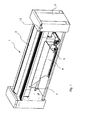
- the FIG. 1 shows an ironing machine 1 in the manner of a defect.
- the ironing machine 1 in this case comprises a frame 2, in which a roller 3 is rotatably mounted.
- the roller 3 is in a trough area 4, to form a cup-shaped smoothing space for textiles.
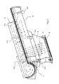
- the trough region 4 is in this case provided with a heater 6 acting over the trough surface 5, as this example in the FIG. 3 is hinted at.
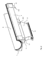
- the trough region 4 consists of a channel space 7 arranged at the rear side of the trough surface 5 through which a medium consisting of hot gas H, indicated by the arrows in FIG FIG. 4 , flows.
- the channel space 7 is, as in particular from FIG.
- the ironing machine 1 further comprises a control device 13, which controls the heating device 6, the drive of the roller 3 and in a preferred embodiment, the control elements 10, 10.1, 10.2, 10.3 ( Fig. 5 ) for influencing the hot gas flow H ( Fig. 4 ) serves.
- each output channel is 9.1, 9.2, 9.3 provided with a control element 10.1, 10.2, 10.3.
- the control elements 10.1, 10.2 and 10.3 for optimized heat distribution in the channel space 7 are independently controllable in the three output channels 9.1, 9.2, 9.3.
- a first output channel 9.1 and a second output channel 9.2 is provided in each case at the end of the channel space 7, wherein a third output channel 9.3 between the first and the second output channel 9.1 and 9.2 is arranged.
- the three output channels 9.1, 9.2 and 9.3 open into a common exhaust duct, not shown.
- the hot gas stream H is divided here into several partial streams H.1, H.2 and H.3.
- the hot gas partial flow H.1 flows with the highest volume flow through the first outlet channel 9.1, which is completely opened by means of the regulating member 10.1 mounted therein.
- the hot gas partial flow H2 flows with an average volume flow through the second outlet channel 9.2, which is half open by means of the control element 10.2 mounted therein.
- the hot gas partial stream H3 flows with about one third or one fourth of the maximum possible volume flow through the third outlet channel 9.3, which is opened by means of the control member 10.3 mounted therein to a third or a quarter.
- the volume flows of the hot gas partial flows H.1, H.2, H.3 can be dimensioned or set almost arbitrarily.
- the output channels 9.1, 9.2, 9.3 can also be completely closed, so that then the hot gas stream H is not passed through these channels 9.1, 9.2, 9.3.
- at least one of the output channels 9.1, 9.2, 9.3 must be open, so that in general a hot gas flow H is made possible.
- control elements 10.1, 10.2 and 10.3 in this case comprise a pivotally mounted at least in a pipe socket 11 flap 12, as this example, in the FIG. 5 is shown in individual representations. Like from the FIG. 5 can be clearly seen from the three views, are the control element 10.1 in the outlet channel 9.1 in the open position, the control element 10.2 in the output channel 9.2 in the partial open position or the approximately half-open position and the control element 10.3 in the output channel 9.3 in the closed position.
- the control element 10.1, 10.2, 10.3 is dimensioned so that in the closed position, a gap to the inner channel wall side remains free, so that a small hot gas flow can be ensured to avoid exhaust gas.
- the pivotally mounted flaps 12 in the pipe socket 11 can be controlled, which can be done for example with a bi-metal or by means of a thermoelectric control that can be arranged in the trough panel.
- the exhaust gas flow controlled accordingly is that here the flap 12 either opens or closes.
- a modifiable heat distribution in the trough area 4 is achieved, which does not require waiting time by subsequent heating.
Landscapes
- Engineering & Computer Science (AREA)
- Textile Engineering (AREA)
- Treatment Of Fiber Materials (AREA)
- Irons (AREA)
Abstract
Description
- Die Erfindung betrifft eine Bügelmaschine nach Art einer Mangel umfassend eine in einem Muldenbereich drehbar gelagerte Walze zur Bildung eines schalenförmigen Glättungsraumes für Textilien, wobei der Muldenbereich mit einer über die Muldenfläche wirkenden Heizeinrichtung versehen ist, die aus einem an der Rückseite der Muldenaußenfläche angeordneten Kanalraum besteht durch den ein aus Heißgas bestehendes Heizmedium strömt, wobei der Kanalraum mit einem für den Zustrom des Heißgases gemeinsamen Eingangskanal verbunden ist sowie mit wenigstens einem Ausgangskanal für den Abluftstrom beziehungsweise den Abgasstrom.
- Aus dem Stand der Technik, beispielsweise der
DE 44 43 094 C2 , sind Bügelmaschinen nach Art einer Mangel bekannt, wobei diese aus einer Walze bestehen, die in einem Muldenbereich drehbar gelagert ist. Zur Bereitstellung der notwendigen Wärme für den Bügelprozess, wird ein Heizmedium in Form von Heißluft oder Heizgas, das mittels eines Brenners oder Heizkessels erzeugt wird durch den Muldenbereich geleitet, so dass die Außenfläche, an der die Walze vorbeigeführt wird, für den Glättungsprozess beheizt wird. Die Heizvorrichtung besteht hierbei aus einem an der Rückseite der Muldenaußenfläche angeordneten Kanalraum, durch den das Heißgas geführt wird, wobei der Kanalraum mit einem für den Zustrom des Heißgases gemeinsamen Eingangskanal verbunden ist. Das durch den Eingangskanal strömende Heißgas wird dann über die gesamte Muldenlänge geführt, so dass das Heißgas dann über einen Ausgangskanal für den Abluftstrom beziehungsweise den Abgasstrom wieder abgeleitet wird, bevor dies dann mittels des Brenners wieder aufgeheizt wird, so dass das Heißgas über dem Muldenbereich zirkuliert. - Bei dieser nach dem Stand der Technik bekannten Bügelmaschine wird es als nachteilig angesehen, dass die Wärmeverteilung in dem Muldenbereich oft ungenügend ist, zumal beim Bügelprozess infolge von feuchten Textilien, die in den Glättungsspalt eingezogen werden, es im Muldenbereich es zu Wärmedifferenzen kommt, die im Besonderen im Einzugsbereich eine starke Abkühlung des Gases hervorrufen. Die Folge ist, dass es bei dem einseitigen Kaltmangeln in der Mulde zu Wartezeiten kommt, weil ein Wiederaufheizen erforderlich ist, um auf diese Weise dann einen Glättungsprozess beziehungsweise eine entsprechende Mangelqualität zu erhalten.
- Der Erfindung stellt sich somit das Problem, eine Bügelmaschine nach Art einer Mangel derart weiterzubilden, bei der eine optimierte und bedarfsgerechte Beheizung im Muldenbereich durch die Heißgase zur Verfügung gestellt werden.
- Erfindungsgemäß wird dieses Problem durch eine Bügelmaschine mit den Merkmalen des Patentanspruchs 1 gelöst. Vorteilhafte Ausgestaltungen und Weiterbildungen der Erfindung ergeben sich aus den nachfolgenden abhängigen Ansprüchen.
- Die mit der Erfindung erreichten Vorteile bestehen nun darin, dass aufgrund der Regelung der Abluft für eine optimale Wärmeverteilung in dem Kanalraum bei einseitigem Mangeln gesorgt wird. Dabei ist es nicht erforderlich, dass die Heizung abgeschaltet werden muss, so dass eine Wartezeit durch nachträgliches Aufheizen sich erübrigt. Bei einseitiger Wäscheeingabe in diesem Bereich werden die warmen Heißgase durch die geöffneten Klappen in den mehr beanspruchten Bereich geleitet. Durch das Öffnen oder Schließen der jeweiligen Klappe kann der Heißgasstrom in den Wärme benötigten Bereich geleitet werden. Die Steuerung wird selbsttätig durch Regelorgane / Steuerorgane (Bi-Metall) in bzw. an den Klappen geregelt. Durch nicht bemangelte Muldenbereiche und daraus resultierende geringe Wärmeabnahme steigt die Temperatur an den Regelorganen / Steuerorganen (Bi-Metall) und die entsprechende Klappe verringert den Abluftstutzenquerschnitt. Durch eine elektrisch gesteuerte Abluftleitung im Bereich der Muldenverkleidung wird für die Umlenkung der Heißgase in dem Muldenbereich, der gerade bemangelt wird, gesorgt. Hierdurch erfolgt eine gleichmäßige Wärmeverteilung in der Mulde auch bei einseitiger Bemangelung.
- Hierbei können die Klappen durch Regelorgane (Bi-Metall) thermoelektrisch im Abluftstrom oder vor dem Abluftstutzen stufenlos von geöffnet bis geschlossen gesteuert werden.
- Erfindungsgemäß ist daher an wenigstens einem Ausgangskanal für den Abluftstrom beziehungsweise Abgasstrom ein Regelorgan vorgesehen zur Beeinflussung der Wärmeverteilung in dem an der Rückseite bzw. der Außenseite der Mulde angeordneten Kanalraumes. Dabei sind zumindest drei Ausgangskanäle für den Abluftstrom vorgesehen. Jeder Ausgangskanal ist hierbei mit einem Regelorgan ausgestattet. Die Regelorgane sind zur optimierten Wärmeverteilung in den Kanalraum in den drei Ausgangskanälen unabhängig voneinander ansteuerbar.
- Nach einer besonders vorteilhaften Ausgestaltung der Erfindung sind ein erster Ausgangskanal und ein zweiter Ausgangskanal jeweils am Ende des Kanalraumes vorgesehen, wobei ein dritter Ausgangskanal zwischen dem ersten und dem zweiten Ausgangskanal angeordnet ist. Die drei Ausgangskanäle münden hierbei in eine Abluftleitung. In Weiterbildung der Erfindung umfassen die Regelorgane zumindest in einem Rohrstutzen schwenkbar gelagerte Klappen, wobei die schwenkbar gelagerte Klappe mittels eines Bi-Metalls beziehungsweise mittels einer thermoelektrischen Steuerung ansteuerbar ist. In einer bevorzugten Ausführung der Erfindung sind das/die Regelorgan/Regelorgane bzw. die schwenkbaren Klappen mittels der Gerätesteuereinrichtung ansteuerbar. Dadurch kann der Gesamtprozess hinsichtlich weiterer Parameter und Einflussgrößen, wie beispielsweise Textileigenschaften,
- Walzendrehgeschwindigkeit optimal gesteuert werden zur Erreichung eines vordefinierten Bügelergebnisses.
- Ein Ausführungsbeispiel der Erfindung ist in den Zeichnungen rein schematisch dargestellt und wird nachfolgend näher beschrieben. Es zeigt:
- Figur 1
- eine perspektivische Darstellung einer Bügelmaschine;
- Figur 2
- eine weitere perspektivische Darstellung des Muldenbereichs mit Eingangskanal für das Heißgas;
- Figur 3
- eine Seitenansicht des Muldenbereichs mit dem gemeinsamen Eingangskanal;
- Figur 4
- eine perspektivische Darstellung des Muldenbereichs mit Eingangskanals sowie mit Pfeildarstellungen zur Veranschaulichung des Abluftstromes beziehungsweise Abgasstromes im Kanalraum; und
- Figur 5
- Seitenansichten von Rohrstutzen mit den schwenkbar angeordneten Klappen in drei unterschiedlichen Stellungen.
- Die
Figur 1 zeigt eine Bügelmaschine 1 nach Art einer Mangel. Die Bügelmaschine 1 umfasst hierbei ein Gestell 2, in dem eine Walze 3 drehbar gelagert ist. Dabei liegt die Walze 3 in einem Muldenbereich 4, zur Bildung eines schalenförmigen Glättungsraumes für Textilien. Der Muldenbereich 4 ist hierbei mit einer über die Muldenfläche 5 wirkenden Heizeinrichtung 6 versehen, wie diese beispielsweise in derFigur 3 angedeutet wird. Der Muldenbereich 4 besteht aus einem an der Rückseite der Muldenfläche 5 angeordneten Kanalraum 7, durch den ein aus Heißgas H bestehendes Medium, angedeutet durch die Pfeile in derFigur 4 , strömt. Der Kanalraum 7 ist, wie insbesondere aus derFigur 2 und3 deutlich wird, mit einem für den Zustrom des Heißgases H gemeinsamen Eingangskanal 8 verbunden, sowie mit wenigstens einem Ausgangskanal 9 für den Abluftstrom beziehungsweise den Abgasstrom, wie dies ebenfalls aus der Figur deutlich wird. Dabei ist an wenigstens einem Ausgangskanal 9 für den Abluftstrom beziehungsweise Abgasstrom ein Regelorgan 10 vorgesehen, wie dies in derFigur 3 , aber auch in derFigur 5 in Einzeldarstellung gezeigt wird. Das Regelorgan 10 ist zur Beeinflussung der Wärmeverteilung in dem an der Rückseite der Muldenfläche 5 angeordneten Kanalraum 7 vorgesehen. Die Bügelmaschine 1 umfasst ferner eine Steuereinrichtung 13, die zur Steuerung der Heizeinrichtung 6, des Antriebes der Walze 3 und in einer bevorzugten Ausführung die Regelorgane 10, 10.1, 10.2, 10.3 (Fig. 5 ) für die Beeinflussung des Heißgasstromes H (Fig. 4 ) dient. - Wie insbesondere aus der
Figur 2 und auch aus derFigur 5 ersichtlich ist, sind drei Ausgangskanäle 9.1, 9.2 und 9.3 für den Abluftstrom vorgesehen. Dabei ist jeder Ausgangskanal 9.1, 9.2, 9.3 mit einem Regelorgan 10.1, 10.2, 10.3 versehen. Die Regelorgane 10.1, 10.2 und 10.3 zur optimierten Wärmeverteilung in dem Kanalraum 7 sind dabei in den drei Ausgangskanälen 9.1, 9.2, 9.3 unabhängig voneinander ansteuerbar. Wie insbesondere aus derFigur 4 deutlich zu erkennen ist, ist ein erster Ausgangskanal 9.1 und ein zweiter Ausgangskanal 9.2 jeweils am Ende des Kanalraums 7 vorgesehen, wobei ein dritter Ausgangskanal 9.3 zwischen dem ersten und dem zweiten Ausgangskanal 9.1 und 9.2 angeordnet ist. Dabei münden die drei Ausgangskanäle 9.1, 9.2 und 9.3 in einen nicht näher dargestellten gemeinsamen Abgaskanal. InFig. 4 ist ferner die Situation einer unterschiedlichen Heißgasströmung und damit kotrolliert unterschiedlicher Wärmeverteilung in der Muldenfläche 5 skizziert. Der Heißgasstrom H teilt sich hierbei in mehrere Teilströme H.1, H.2 und H.3 auf. Der Heißgasteilstrom H.1 strömt dabei mit höchstem Volumenstrom durch den ersten Ausgangskanal 9.1, der mittels des darin angebrachten Regelorgans 10.1 vollständig geöffnet ist. Der Heißgasteilstrom H2 strömt dabei mit einem mittleren Volumenstrom durch den zweiten Ausgangskanal 9.2, der mittels des darin angebrachten Regelorgans 10.2 halb geöffnet ist. Der Heißgasteilstrom H3 strömt dabei mit einem etwa einem Drittel oder einem Vierten des maximal möglichen Volumenstromes durch den dritten Ausgangskanal 9.3, der mittels des darin angebrachten Regelorgans 10.3 zu einem Drittel oder einem Viertel geöffnet ist. Entsprechend der Position der Regelorgane 10.1, 10.2, 10.3 können die Volumenströme der Heißgasteilströme H.1, H.2, H.3 nahezu beliebig dimensioniert oder eingestellt werden. Die Ausgangskanäle 9.1, 9.2, 9.3 können auch vollständig geschlossen werden, sodass dann der Heißgasstrom H entsprechend nicht durch diese Kanäle 9.1, 9.2, 9.3 geleitet wird. Zumindest einer der Ausgangskanäle 9.1, 9.2, 9.3 muss jedoch geöffnet sein, damit generell ein Heißgasstrom H ermöglicht wird. - Die Regelorgane 10.1, 10.2 und 10.3 umfassen hierbei eine zumindest in einem Rohrstutzen 11 schwenkbar gelagerte Klappe 12, wie diese beispielsweise in der
Figur 5 in Einzeldarstellungen gezeigt wird. Wie aus derFigur 5 aus den drei Ansichten deutlich zu erkennen ist, befinden sich das Regelorgans 10.1 im Ausgangskanal 9.1 in der Offenstellung, das Regelorgan 10.2 im Ausgangskanal 9.2 in der teilweisen Offenstellung bzw. der etwa halb geöffneten Stellung und das Regelorgan 10.3 im Ausgangskanal 9.3 in der verschlossenen Stellung. In einer bevorzugten Ausführung ist das Regelorgan 10.1, 10.2, 10.3 so dimensioniert, dass in der verschlossenen Stellung ein Spalt zur inneren Kanalwandseite frei bleibt, damit ein geringer Heißgassrom zur Vermeidung eines Abgasstaus sichergestellt werden kann. - Dabei sind die schwenkbar gelagerten Klappen 12 in dem Rohrstutzen 11 ansteuerbar, wobei dies beispielsweise mit einem Bi-Metall erfolgen kann oder aber auch mittels einer thermoelektrischen Steuerung, die in der Muldenverkleidung angeordnet sein kann. Es versteht sich nun von selbst, dass, wenn bei einem einseitigen Mangeln eine optimale Wärmeverteilung gegeben werden soll, insbesondere der Wärmestrom dort, wo er hinsichtlich seiner Ansteuerung und der Temperaturdifferenz entsprechend gering ausfällt, der Abgasstrom entsprechend dadurch gesteuert wird, dass hier die Klappe 12 entweder öffnet oder schließt. Somit wird eine beeinflussbare Wärmeverteilung im Muldenbereich 4 erreicht, die keine Wartezeit durch nachträgliches Aufheizen erfordert.
Claims (10)
- Bügelmaschine (1) nach Art einer Mangel umfassend eine in einem Muldenbereich (4) drehbar gelagerte Walze (3) zur Bildung eines schalenförmigen Glättungsraumes für Textilien, wobei der Muldenbereich (4) mit einer über die Muldenfläche (5) wirkenden Heizeinrichtung (6) versehen ist, die aus einem an der Rückseite der Muldenaußenfläche angeordneten Kanalraum (7) besteht, durch den ein aus Heißgas bestehendes Heizmedium strömt, wobei der Kanalraum (7) mit einem für den Zustrom des Heißgases gemeinsamen Eingangskanal (8) verbunden ist, sowie mit wenigstens einem Ausgangskanal (9) für den Abluftstrom bzw. Abgasstrom,
dadurch gekennzeichnet,
dass am Ausgangskanal (9) für den Abluftstrom bzw. Abgasstrom ein Regelorgan (10) vorgesehen ist, mit dem der Heißgasstrom (H, H.1, H.2, H.3) in den Wärme benötigten Bereich geleitet werden kann zur Beeinflussung der Wärmeverteilung in dem an der Rückseite der Muldenfläche (5) angeordneten Kanalraumes (7). - Bügelmaschine nach Anspruch 1,
dadurch gekennzeichnet,
dass zumindest drei Ausgangskanäle (9.1, 9.2, 9.3) für den Abluftstrom vorgesehen sind. - Bügelmaschine nach Anspruch 2,
dadurch gekennzeichnet,
dass jeder Ausgangskanal (9.1, 9.2, 9.3) jeweils mit einem Regelorgan (10) versehen ist. - Bügelmaschine nach Anspruch 3,
dadurch gekennzeichnet,
dass die Regelorgane (10) zur optimierten Wärmeverteilung in dem Kanalraum (7) in den drei Ausgangskanälen (9.1, 9.2, 9.3) unabhängig voneinander ansteuerbar sind. - Bügelmaschine nach einem der Ansprüche 2 bis 4,
dadurch gekennzeichnet,
dass ein erster Ausgangskanal (9.1) und ein zweiter Ausgangskanal (9.3) jeweils am Ende des Kanalraumes (7) vorgesehen ist, wobei ein dritter Ausgangkanal (9.2) zwischen dem ersten und dem zweiten Ausgangskanal (9.1) und (9.3) angeordnet ist. - Bügelmaschine nach Anspruch 2,
dadurch gekennzeichnet,
dass die drei Ausgangskanäle (9.1, 9.2, 9.3) in eine Abgasleitung münden. - Bügelmaschine nach Anspruch 1 bis 4,
dadurch gekennzeichnet,
dass die Regelorgane (10) eine zumindest in einem Rohrstutzen (11) schwenkbar gelagerte Klappe (12) umfassen. - Bügelmaschine nach Anspruch 7,
dadurch gekennzeichnet,
dass die schwenkbar gelagerte Klappe (12) mittels eines Bi-Metalls ansteuerbar ist. - Bügelmaschine nach Anspruch 7,
dadurch gekennzeichnet,
dass die schwenkbar gelagerte Klappe (12) mittels einer thermo-elektrischen Steuerung ansteuerbar ist. - Bügelmaschine nach einem der Ansprüche 1 bis 7,
dadurch gekennzeichnet,
dass das/die Regelorgan/Regelorgane (10, 10.1, 10.2, 10.3) bzw. die schwenkbaren Klappen (12) mittels der Gerätesteuereinrichtung (13) ansteuerbar sind.
Applications Claiming Priority (1)
| Application Number | Priority Date | Filing Date | Title |
|---|---|---|---|
| DE102012105834.2A DE102012105834A1 (de) | 2012-07-02 | 2012-07-02 | Bügelmaschine nach Art einer Mangel |
Publications (3)
| Publication Number | Publication Date |
|---|---|
| EP2682516A2 true EP2682516A2 (de) | 2014-01-08 |
| EP2682516A3 EP2682516A3 (de) | 2014-02-26 |
| EP2682516B1 EP2682516B1 (de) | 2015-08-12 |
Family
ID=48700511
Family Applications (1)
| Application Number | Title | Priority Date | Filing Date |
|---|---|---|---|
| EP13401059.4A Not-in-force EP2682516B1 (de) | 2012-07-02 | 2013-06-11 | Bügelmaschine nach Art einer Mangel |
Country Status (3)
| Country | Link |
|---|---|
| EP (1) | EP2682516B1 (de) |
| DE (1) | DE102012105834A1 (de) |
| ES (1) | ES2549968T3 (de) |
Cited By (2)
| Publication number | Priority date | Publication date | Assignee | Title |
|---|---|---|---|---|
| WO2015155648A1 (en) * | 2014-04-07 | 2015-10-15 | Werkhuizen Lapauw Nv | Ironer chest for an ironing device |
| BE1022093B1 (nl) * | 2014-04-07 | 2016-02-15 | Werkhuizen Lapauw Nv | Mangelkuip voor een strijkinrinchting |
Citations (1)
| Publication number | Priority date | Publication date | Assignee | Title |
|---|---|---|---|---|
| DE4443094C2 (de) | 1994-12-03 | 1997-12-18 | Miele & Cie | Fremdbeheizte Mulde für eine Muldenmangel oder Bügelmaschine |
Family Cites Families (3)
| Publication number | Priority date | Publication date | Assignee | Title |
|---|---|---|---|---|
| US2195937A (en) * | 1937-03-12 | 1940-04-02 | Baker Perkins Ltd | Laundry ironing machine |
| DD264042B3 (de) * | 1987-08-28 | 1993-01-14 | Aue Textilmaschinenbau Gmbh | Verfahren zum beheizen einer mangelmulde sowie schaltungsanordnung hierfuer |
| DE3838391A1 (de) * | 1988-11-12 | 1990-05-17 | Effma Waeschereitechnik & Masc | Mangel |
-
2012
- 2012-07-02 DE DE102012105834.2A patent/DE102012105834A1/de not_active Ceased
-
2013
- 2013-06-11 ES ES13401059.4T patent/ES2549968T3/es active Active
- 2013-06-11 EP EP13401059.4A patent/EP2682516B1/de not_active Not-in-force
Patent Citations (1)
| Publication number | Priority date | Publication date | Assignee | Title |
|---|---|---|---|---|
| DE4443094C2 (de) | 1994-12-03 | 1997-12-18 | Miele & Cie | Fremdbeheizte Mulde für eine Muldenmangel oder Bügelmaschine |
Cited By (3)
| Publication number | Priority date | Publication date | Assignee | Title |
|---|---|---|---|---|
| WO2015155648A1 (en) * | 2014-04-07 | 2015-10-15 | Werkhuizen Lapauw Nv | Ironer chest for an ironing device |
| BE1022093B1 (nl) * | 2014-04-07 | 2016-02-15 | Werkhuizen Lapauw Nv | Mangelkuip voor een strijkinrinchting |
| US10179969B2 (en) | 2014-04-07 | 2019-01-15 | Werkhuizen Lapauw Nv | Ironer chest for an ironing device |
Also Published As
| Publication number | Publication date |
|---|---|
| EP2682516B1 (de) | 2015-08-12 |
| DE102012105834A1 (de) | 2014-01-02 |
| EP2682516A3 (de) | 2014-02-26 |
| ES2549968T3 (es) | 2015-11-03 |
Similar Documents
| Publication | Publication Date | Title |
|---|---|---|
| EP2194183B1 (de) | Trockner mit Umluftanteil sowie Verfahren zu seinem Betrieb | |
| EP2199454B1 (de) | Hausgerät mit einem offenen Luftkanal | |
| DE102008033388A1 (de) | Trockner mit Wärmepumpenkreis | |
| DE112008002131T5 (de) | Wasch-Trocknungssystem mit Waschmaschine und Trockner, sowie Verfahren zur Steuerung der Wasserversorgung desselben | |
| WO2018033384A1 (de) | Haushaltsgargerät | |
| EP3138951B1 (de) | Anordnung und verfahren zum einleiten von prozessluft in eine wäschetrommel eines wäschetrockners | |
| EP2682516B1 (de) | Bügelmaschine nach Art einer Mangel | |
| EP3026167B1 (de) | Wäschetrocknungsgerät und verfahren zum betreiben eines wäschetrocknungsgeräts | |
| DE102011114302A1 (de) | Lüftungsgerät mit Wärmerückgewinnung | |
| DE1432588A1 (de) | Verfahren und Vorrichtung fuer die einheitliche Konditionierung von Tabakblaettern | |
| EP2210976B1 (de) | Wäschebehandlungsmaschine, wie beispielsweise ein Wäschetrockner | |
| DE102014010498B4 (de) | Verfahren zum Trocknen von Wäsche und Trockner | |
| EP2679719B1 (de) | Bügelmaschine nach Art einer Mangel | |
| EP1987191A2 (de) | Verfahren zum mangeln von wäschestücken und muldenmangel | |
| DE581650C (de) | Lufttrockenschlichtmaschine | |
| DE10237652A1 (de) | Backofen sowie Verfahren zum Beschwaden mindestens eines ausgewählten Backraums eines Backofens | |
| DE102007062013A1 (de) | Vorrichtung zum Bügeln | |
| EP3447390B1 (de) | Gargerät, insbesondere gewerbliches gargerät | |
| DE102020214557A1 (de) | Tür für ein Wäschebehandlungsgerät, insbesondere für einen Wäschetrockner oder Waschtrockner | |
| DE2820115A1 (de) | Verfahren und anlage zur beeinflussung der raumlufttemperatur | |
| DE29608284U1 (de) | Tiefkühlgerät | |
| DE974283C (de) | Als Mansarde hinter einer Druckmaschine angeordneter Duesentrockner fuer Textilien | |
| DE202015101389U1 (de) | Kaminkassette mit verbesserter Luftführung | |
| DE102004034210B4 (de) | Verfahren und Vorrichtung zur Belüftung und Temperierung | |
| DE509904C (de) | Kanaltrockner |
Legal Events
| Date | Code | Title | Description |
|---|---|---|---|
| PUAI | Public reference made under article 153(3) epc to a published international application that has entered the european phase |
Free format text: ORIGINAL CODE: 0009012 |
|
| AK | Designated contracting states |
Kind code of ref document: A2 Designated state(s): AL AT BE BG CH CY CZ DE DK EE ES FI FR GB GR HR HU IE IS IT LI LT LU LV MC MK MT NL NO PL PT RO RS SE SI SK SM TR |
|
| AX | Request for extension of the european patent |
Extension state: BA ME |
|
| PUAL | Search report despatched |
Free format text: ORIGINAL CODE: 0009013 |
|
| AK | Designated contracting states |
Kind code of ref document: A3 Designated state(s): AL AT BE BG CH CY CZ DE DK EE ES FI FR GB GR HR HU IE IS IT LI LT LU LV MC MK MT NL NO PL PT RO RS SE SI SK SM TR |
|
| AX | Request for extension of the european patent |
Extension state: BA ME |
|
| RIC1 | Information provided on ipc code assigned before grant |
Ipc: D06F 67/08 20060101AFI20140117BHEP |
|
| 17P | Request for examination filed |
Effective date: 20140826 |
|
| RBV | Designated contracting states (corrected) |
Designated state(s): AL AT BE BG CH CY CZ DE DK EE ES FI FR GB GR HR HU IE IS IT LI LT LU LV MC MK MT NL NO PL PT RO RS SE SI SK SM TR |
|
| GRAP | Despatch of communication of intention to grant a patent |
Free format text: ORIGINAL CODE: EPIDOSNIGR1 |
|
| INTG | Intention to grant announced |
Effective date: 20150212 |
|
| GRAS | Grant fee paid |
Free format text: ORIGINAL CODE: EPIDOSNIGR3 |
|
| GRAA | (expected) grant |
Free format text: ORIGINAL CODE: 0009210 |
|
| AK | Designated contracting states |
Kind code of ref document: B1 Designated state(s): AL AT BE BG CH CY CZ DE DK EE ES FI FR GB GR HR HU IE IS IT LI LT LU LV MC MK MT NL NO PL PT RO RS SE SI SK SM TR |
|
| REG | Reference to a national code |
Ref country code: GB Ref legal event code: FG4D Free format text: NOT ENGLISH |
|
| REG | Reference to a national code |
Ref country code: CH Ref legal event code: EP |
|
| REG | Reference to a national code |
Ref country code: AT Ref legal event code: REF Ref document number: 742274 Country of ref document: AT Kind code of ref document: T Effective date: 20150815 |
|
| REG | Reference to a national code |
Ref country code: DE Ref legal event code: R084 Ref document number: 502013001020 Country of ref document: DE |
|
| REG | Reference to a national code |
Ref country code: IE Ref legal event code: FG4D Free format text: LANGUAGE OF EP DOCUMENT: GERMAN |
|
| REG | Reference to a national code |
Ref country code: DE Ref legal event code: R096 Ref document number: 502013001020 Country of ref document: DE |
|
| REG | Reference to a national code |
Ref country code: ES Ref legal event code: GC2A Effective date: 20151021 |
|
| REG | Reference to a national code |
Ref country code: ES Ref legal event code: FG2A Ref document number: 2549968 Country of ref document: ES Kind code of ref document: T3 Effective date: 20151103 |
|
| REG | Reference to a national code |
Ref country code: LT Ref legal event code: MG4D |
|
| REG | Reference to a national code |
Ref country code: NL Ref legal event code: MP Effective date: 20150812 |
|
| PG25 | Lapsed in a contracting state [announced via postgrant information from national office to epo] |
Ref country code: FI Free format text: LAPSE BECAUSE OF FAILURE TO SUBMIT A TRANSLATION OF THE DESCRIPTION OR TO PAY THE FEE WITHIN THE PRESCRIBED TIME-LIMIT Effective date: 20150812 Ref country code: GR Free format text: LAPSE BECAUSE OF FAILURE TO SUBMIT A TRANSLATION OF THE DESCRIPTION OR TO PAY THE FEE WITHIN THE PRESCRIBED TIME-LIMIT Effective date: 20151113 Ref country code: LT Free format text: LAPSE BECAUSE OF FAILURE TO SUBMIT A TRANSLATION OF THE DESCRIPTION OR TO PAY THE FEE WITHIN THE PRESCRIBED TIME-LIMIT Effective date: 20150812 Ref country code: LV Free format text: LAPSE BECAUSE OF FAILURE TO SUBMIT A TRANSLATION OF THE DESCRIPTION OR TO PAY THE FEE WITHIN THE PRESCRIBED TIME-LIMIT Effective date: 20150812 Ref country code: NO Free format text: LAPSE BECAUSE OF FAILURE TO SUBMIT A TRANSLATION OF THE DESCRIPTION OR TO PAY THE FEE WITHIN THE PRESCRIBED TIME-LIMIT Effective date: 20151112 |
|
| PG25 | Lapsed in a contracting state [announced via postgrant information from national office to epo] |
Ref country code: RS Free format text: LAPSE BECAUSE OF FAILURE TO SUBMIT A TRANSLATION OF THE DESCRIPTION OR TO PAY THE FEE WITHIN THE PRESCRIBED TIME-LIMIT Effective date: 20150812 Ref country code: PL Free format text: LAPSE BECAUSE OF FAILURE TO SUBMIT A TRANSLATION OF THE DESCRIPTION OR TO PAY THE FEE WITHIN THE PRESCRIBED TIME-LIMIT Effective date: 20150812 Ref country code: IS Free format text: LAPSE BECAUSE OF FAILURE TO SUBMIT A TRANSLATION OF THE DESCRIPTION OR TO PAY THE FEE WITHIN THE PRESCRIBED TIME-LIMIT Effective date: 20151212 Ref country code: HR Free format text: LAPSE BECAUSE OF FAILURE TO SUBMIT A TRANSLATION OF THE DESCRIPTION OR TO PAY THE FEE WITHIN THE PRESCRIBED TIME-LIMIT Effective date: 20150812 Ref country code: SE Free format text: LAPSE BECAUSE OF FAILURE TO SUBMIT A TRANSLATION OF THE DESCRIPTION OR TO PAY THE FEE WITHIN THE PRESCRIBED TIME-LIMIT Effective date: 20150812 Ref country code: PT Free format text: LAPSE BECAUSE OF FAILURE TO SUBMIT A TRANSLATION OF THE DESCRIPTION OR TO PAY THE FEE WITHIN THE PRESCRIBED TIME-LIMIT Effective date: 20151214 |
|
| PG25 | Lapsed in a contracting state [announced via postgrant information from national office to epo] |
Ref country code: NL Free format text: LAPSE BECAUSE OF FAILURE TO SUBMIT A TRANSLATION OF THE DESCRIPTION OR TO PAY THE FEE WITHIN THE PRESCRIBED TIME-LIMIT Effective date: 20150812 |
|
| PG25 | Lapsed in a contracting state [announced via postgrant information from national office to epo] |
Ref country code: SK Free format text: LAPSE BECAUSE OF FAILURE TO SUBMIT A TRANSLATION OF THE DESCRIPTION OR TO PAY THE FEE WITHIN THE PRESCRIBED TIME-LIMIT Effective date: 20150812 Ref country code: DK Free format text: LAPSE BECAUSE OF FAILURE TO SUBMIT A TRANSLATION OF THE DESCRIPTION OR TO PAY THE FEE WITHIN THE PRESCRIBED TIME-LIMIT Effective date: 20150812 Ref country code: EE Free format text: LAPSE BECAUSE OF FAILURE TO SUBMIT A TRANSLATION OF THE DESCRIPTION OR TO PAY THE FEE WITHIN THE PRESCRIBED TIME-LIMIT Effective date: 20150812 |
|
| REG | Reference to a national code |
Ref country code: DE Ref legal event code: R097 Ref document number: 502013001020 Country of ref document: DE |
|
| PG25 | Lapsed in a contracting state [announced via postgrant information from national office to epo] |
Ref country code: RO Free format text: LAPSE BECAUSE OF FAILURE TO SUBMIT A TRANSLATION OF THE DESCRIPTION OR TO PAY THE FEE WITHIN THE PRESCRIBED TIME-LIMIT Effective date: 20150812 |
|
| PLBE | No opposition filed within time limit |
Free format text: ORIGINAL CODE: 0009261 |
|
| STAA | Information on the status of an ep patent application or granted ep patent |
Free format text: STATUS: NO OPPOSITION FILED WITHIN TIME LIMIT |
|
| REG | Reference to a national code |
Ref country code: FR Ref legal event code: PLFP Year of fee payment: 4 |
|
| 26N | No opposition filed |
Effective date: 20160513 |
|
| PG25 | Lapsed in a contracting state [announced via postgrant information from national office to epo] |
Ref country code: SI Free format text: LAPSE BECAUSE OF FAILURE TO SUBMIT A TRANSLATION OF THE DESCRIPTION OR TO PAY THE FEE WITHIN THE PRESCRIBED TIME-LIMIT Effective date: 20150812 |
|
| PG25 | Lapsed in a contracting state [announced via postgrant information from national office to epo] |
Ref country code: MC Free format text: LAPSE BECAUSE OF FAILURE TO SUBMIT A TRANSLATION OF THE DESCRIPTION OR TO PAY THE FEE WITHIN THE PRESCRIBED TIME-LIMIT Effective date: 20150812 |
|
| REG | Reference to a national code |
Ref country code: CH Ref legal event code: PL |
|
| REG | Reference to a national code |
Ref country code: IE Ref legal event code: MM4A |
|
| PG25 | Lapsed in a contracting state [announced via postgrant information from national office to epo] |
Ref country code: LI Free format text: LAPSE BECAUSE OF NON-PAYMENT OF DUE FEES Effective date: 20160630 Ref country code: CH Free format text: LAPSE BECAUSE OF NON-PAYMENT OF DUE FEES Effective date: 20160630 |
|
| PG25 | Lapsed in a contracting state [announced via postgrant information from national office to epo] |
Ref country code: IE Free format text: LAPSE BECAUSE OF NON-PAYMENT OF DUE FEES Effective date: 20160611 |
|
| REG | Reference to a national code |
Ref country code: FR Ref legal event code: PLFP Year of fee payment: 5 |
|
| GBPC | Gb: european patent ceased through non-payment of renewal fee |
Effective date: 20170611 |
|
| PG25 | Lapsed in a contracting state [announced via postgrant information from national office to epo] |
Ref country code: GB Free format text: LAPSE BECAUSE OF NON-PAYMENT OF DUE FEES Effective date: 20170611 |
|
| PG25 | Lapsed in a contracting state [announced via postgrant information from national office to epo] |
Ref country code: CY Free format text: LAPSE BECAUSE OF FAILURE TO SUBMIT A TRANSLATION OF THE DESCRIPTION OR TO PAY THE FEE WITHIN THE PRESCRIBED TIME-LIMIT Effective date: 20150812 Ref country code: SM Free format text: LAPSE BECAUSE OF FAILURE TO SUBMIT A TRANSLATION OF THE DESCRIPTION OR TO PAY THE FEE WITHIN THE PRESCRIBED TIME-LIMIT Effective date: 20150812 Ref country code: HU Free format text: LAPSE BECAUSE OF FAILURE TO SUBMIT A TRANSLATION OF THE DESCRIPTION OR TO PAY THE FEE WITHIN THE PRESCRIBED TIME-LIMIT; INVALID AB INITIO Effective date: 20130611 |
|
| REG | Reference to a national code |
Ref country code: FR Ref legal event code: PLFP Year of fee payment: 6 |
|
| PG25 | Lapsed in a contracting state [announced via postgrant information from national office to epo] |
Ref country code: LU Free format text: LAPSE BECAUSE OF NON-PAYMENT OF DUE FEES Effective date: 20160611 Ref country code: MT Free format text: LAPSE BECAUSE OF FAILURE TO SUBMIT A TRANSLATION OF THE DESCRIPTION OR TO PAY THE FEE WITHIN THE PRESCRIBED TIME-LIMIT Effective date: 20150812 Ref country code: MK Free format text: LAPSE BECAUSE OF FAILURE TO SUBMIT A TRANSLATION OF THE DESCRIPTION OR TO PAY THE FEE WITHIN THE PRESCRIBED TIME-LIMIT Effective date: 20150812 Ref country code: TR Free format text: LAPSE BECAUSE OF FAILURE TO SUBMIT A TRANSLATION OF THE DESCRIPTION OR TO PAY THE FEE WITHIN THE PRESCRIBED TIME-LIMIT Effective date: 20150812 |
|
| PG25 | Lapsed in a contracting state [announced via postgrant information from national office to epo] |
Ref country code: BG Free format text: LAPSE BECAUSE OF FAILURE TO SUBMIT A TRANSLATION OF THE DESCRIPTION OR TO PAY THE FEE WITHIN THE PRESCRIBED TIME-LIMIT Effective date: 20150812 |
|
| PG25 | Lapsed in a contracting state [announced via postgrant information from national office to epo] |
Ref country code: AL Free format text: LAPSE BECAUSE OF FAILURE TO SUBMIT A TRANSLATION OF THE DESCRIPTION OR TO PAY THE FEE WITHIN THE PRESCRIBED TIME-LIMIT Effective date: 20150812 |
|
| PGFP | Annual fee paid to national office [announced via postgrant information from national office to epo] |
Ref country code: IT Payment date: 20190624 Year of fee payment: 7 Ref country code: CZ Payment date: 20190610 Year of fee payment: 7 |
|
| REG | Reference to a national code |
Ref country code: AT Ref legal event code: MM01 Ref document number: 742274 Country of ref document: AT Kind code of ref document: T Effective date: 20180611 |
|
| PGFP | Annual fee paid to national office [announced via postgrant information from national office to epo] |
Ref country code: FR Payment date: 20190625 Year of fee payment: 7 Ref country code: BE Payment date: 20190625 Year of fee payment: 7 |
|
| PGFP | Annual fee paid to national office [announced via postgrant information from national office to epo] |
Ref country code: ES Payment date: 20190725 Year of fee payment: 7 Ref country code: DE Payment date: 20190630 Year of fee payment: 7 |
|
| PG25 | Lapsed in a contracting state [announced via postgrant information from national office to epo] |
Ref country code: AT Free format text: LAPSE BECAUSE OF NON-PAYMENT OF DUE FEES Effective date: 20180611 |
|
| REG | Reference to a national code |
Ref country code: DE Ref legal event code: R119 Ref document number: 502013001020 Country of ref document: DE |
|
| PG25 | Lapsed in a contracting state [announced via postgrant information from national office to epo] |
Ref country code: CZ Free format text: LAPSE BECAUSE OF NON-PAYMENT OF DUE FEES Effective date: 20200611 |
|
| REG | Reference to a national code |
Ref country code: BE Ref legal event code: MM Effective date: 20200630 |
|
| PG25 | Lapsed in a contracting state [announced via postgrant information from national office to epo] |
Ref country code: FR Free format text: LAPSE BECAUSE OF NON-PAYMENT OF DUE FEES Effective date: 20200630 |
|
| PG25 | Lapsed in a contracting state [announced via postgrant information from national office to epo] |
Ref country code: BE Free format text: LAPSE BECAUSE OF NON-PAYMENT OF DUE FEES Effective date: 20200630 Ref country code: DE Free format text: LAPSE BECAUSE OF NON-PAYMENT OF DUE FEES Effective date: 20210101 |
|
| REG | Reference to a national code |
Ref country code: ES Ref legal event code: FD2A Effective date: 20211027 |
|
| PG25 | Lapsed in a contracting state [announced via postgrant information from national office to epo] |
Ref country code: IT Free format text: LAPSE BECAUSE OF NON-PAYMENT OF DUE FEES Effective date: 20200611 |
|
| PG25 | Lapsed in a contracting state [announced via postgrant information from national office to epo] |
Ref country code: ES Free format text: LAPSE BECAUSE OF NON-PAYMENT OF DUE FEES Effective date: 20200612 |