EP2682056B1 - Dispositif de pénétration de la peau - Google Patents
Dispositif de pénétration de la peau Download PDFInfo
- Publication number
- EP2682056B1 EP2682056B1 EP13185802.9A EP13185802A EP2682056B1 EP 2682056 B1 EP2682056 B1 EP 2682056B1 EP 13185802 A EP13185802 A EP 13185802A EP 2682056 B1 EP2682056 B1 EP 2682056B1
- Authority
- EP
- European Patent Office
- Prior art keywords
- lancet
- release
- holder
- lancet holder
- housing
- Prior art date
- Legal status (The legal status is an assumption and is not a legal conclusion. Google has not performed a legal analysis and makes no representation as to the accuracy of the status listed.)
- Active
Links
- 230000035515 penetration Effects 0.000 title description 11
- 230000000903 blocking effect Effects 0.000 claims description 3
- 230000000670 limiting effect Effects 0.000 claims description 2
- 230000000452 restraining effect Effects 0.000 claims description 2
- 230000009471 action Effects 0.000 description 12
- 210000003813 thumb Anatomy 0.000 description 9
- 238000003780 insertion Methods 0.000 description 5
- 230000037431 insertion Effects 0.000 description 5
- 239000008280 blood Substances 0.000 description 3
- 210000004369 blood Anatomy 0.000 description 3
- 210000003811 finger Anatomy 0.000 description 3
- 230000007246 mechanism Effects 0.000 description 3
- 238000000465 moulding Methods 0.000 description 3
- 230000008901 benefit Effects 0.000 description 2
- 238000010304 firing Methods 0.000 description 2
- 238000002347 injection Methods 0.000 description 2
- 239000007924 injection Substances 0.000 description 2
- 238000004519 manufacturing process Methods 0.000 description 2
- 230000004048 modification Effects 0.000 description 2
- 238000012986 modification Methods 0.000 description 2
- WQZGKKKJIJFFOK-GASJEMHNSA-N Glucose Natural products OC[C@H]1OC(O)[C@H](O)[C@@H](O)[C@@H]1O WQZGKKKJIJFFOK-GASJEMHNSA-N 0.000 description 1
- 208000012266 Needlestick injury Diseases 0.000 description 1
- 230000004913 activation Effects 0.000 description 1
- 238000005452 bending Methods 0.000 description 1
- 230000015572 biosynthetic process Effects 0.000 description 1
- 230000006835 compression Effects 0.000 description 1
- 238000007906 compression Methods 0.000 description 1
- 238000010276 construction Methods 0.000 description 1
- 238000011109 contamination Methods 0.000 description 1
- 230000008602 contraction Effects 0.000 description 1
- 230000000694 effects Effects 0.000 description 1
- 239000008103 glucose Substances 0.000 description 1
- 210000005036 nerve Anatomy 0.000 description 1
- 230000009467 reduction Effects 0.000 description 1
- 230000002829 reductive effect Effects 0.000 description 1
- 239000012858 resilient material Substances 0.000 description 1
- 230000000717 retained effect Effects 0.000 description 1
- 230000002441 reversible effect Effects 0.000 description 1
Images

Classifications
-
- A—HUMAN NECESSITIES
- A61—MEDICAL OR VETERINARY SCIENCE; HYGIENE
- A61B—DIAGNOSIS; SURGERY; IDENTIFICATION
- A61B5/00—Measuring for diagnostic purposes; Identification of persons
- A61B5/15—Devices for taking samples of blood
- A61B5/151—Devices specially adapted for taking samples of capillary blood, e.g. by lancets, needles or blades
- A61B5/15186—Devices loaded with a single lancet, i.e. a single lancet with or without a casing is loaded into a reusable drive device and then discarded after use; drive devices reloadable for multiple use
- A61B5/15188—Constructional features of reusable driving devices
- A61B5/1519—Constructional features of reusable driving devices comprising driving means, e.g. a spring, for propelling the piercing unit
-
- A—HUMAN NECESSITIES
- A61—MEDICAL OR VETERINARY SCIENCE; HYGIENE
- A61B—DIAGNOSIS; SURGERY; IDENTIFICATION
- A61B5/00—Measuring for diagnostic purposes; Identification of persons
- A61B5/14—Devices for taking samples of blood ; Measuring characteristics of blood in vivo, e.g. gas concentration within the blood, pH-value of blood
- A61B5/1405—Devices for taking blood samples
- A61B5/1411—Devices for taking blood samples by percutaneous method, e.g. by lancet
-
- A—HUMAN NECESSITIES
- A61—MEDICAL OR VETERINARY SCIENCE; HYGIENE
- A61B—DIAGNOSIS; SURGERY; IDENTIFICATION
- A61B5/00—Measuring for diagnostic purposes; Identification of persons
- A61B5/15—Devices for taking samples of blood
- A61B5/150007—Details
- A61B5/150015—Source of blood
- A61B5/150022—Source of blood for capillary blood or interstitial fluid
-
- A—HUMAN NECESSITIES
- A61—MEDICAL OR VETERINARY SCIENCE; HYGIENE
- A61B—DIAGNOSIS; SURGERY; IDENTIFICATION
- A61B5/00—Measuring for diagnostic purposes; Identification of persons
- A61B5/15—Devices for taking samples of blood
- A61B5/150007—Details
- A61B5/150053—Details for enhanced collection of blood or interstitial fluid at the sample site, e.g. by applying compression, heat, vibration, ultrasound, suction or vacuum to tissue; for reduction of pain or discomfort; Skin piercing elements, e.g. blades, needles, lancets or canulas, with adjustable piercing speed
- A61B5/150106—Means for reducing pain or discomfort applied before puncturing; desensitising the skin at the location where body is to be pierced
- A61B5/150114—Means for reducing pain or discomfort applied before puncturing; desensitising the skin at the location where body is to be pierced by tissue compression, e.g. with specially designed surface of device contacting the skin area to be pierced
-
- A—HUMAN NECESSITIES
- A61—MEDICAL OR VETERINARY SCIENCE; HYGIENE
- A61B—DIAGNOSIS; SURGERY; IDENTIFICATION
- A61B5/00—Measuring for diagnostic purposes; Identification of persons
- A61B5/15—Devices for taking samples of blood
- A61B5/150007—Details
- A61B5/150175—Adjustment of penetration depth
- A61B5/150183—Depth adjustment mechanism using end caps mounted at the distal end of the sampling device, i.e. the end-caps are adjustably positioned relative to the piercing device housing for example by rotating or screwing
-
- A—HUMAN NECESSITIES
- A61—MEDICAL OR VETERINARY SCIENCE; HYGIENE
- A61B—DIAGNOSIS; SURGERY; IDENTIFICATION
- A61B5/00—Measuring for diagnostic purposes; Identification of persons
- A61B5/15—Devices for taking samples of blood
- A61B5/150007—Details
- A61B5/150374—Details of piercing elements or protective means for preventing accidental injuries by such piercing elements
- A61B5/150381—Design of piercing elements
- A61B5/150412—Pointed piercing elements, e.g. needles, lancets for piercing the skin
-
- A—HUMAN NECESSITIES
- A61—MEDICAL OR VETERINARY SCIENCE; HYGIENE
- A61B—DIAGNOSIS; SURGERY; IDENTIFICATION
- A61B5/00—Measuring for diagnostic purposes; Identification of persons
- A61B5/15—Devices for taking samples of blood
- A61B5/150007—Details
- A61B5/150374—Details of piercing elements or protective means for preventing accidental injuries by such piercing elements
- A61B5/150381—Design of piercing elements
- A61B5/150503—Single-ended needles
-
- A—HUMAN NECESSITIES
- A61—MEDICAL OR VETERINARY SCIENCE; HYGIENE
- A61B—DIAGNOSIS; SURGERY; IDENTIFICATION
- A61B5/00—Measuring for diagnostic purposes; Identification of persons
- A61B5/15—Devices for taking samples of blood
- A61B5/150007—Details
- A61B5/150374—Details of piercing elements or protective means for preventing accidental injuries by such piercing elements
- A61B5/150534—Design of protective means for piercing elements for preventing accidental needle sticks, e.g. shields, caps, protectors, axially extensible sleeves, pivotable protective sleeves
- A61B5/15058—Joining techniques used for protective means
- A61B5/150595—Joining techniques used for protective means by snap-lock (i.e. based on axial displacement)
-
- A—HUMAN NECESSITIES
- A61—MEDICAL OR VETERINARY SCIENCE; HYGIENE
- A61B—DIAGNOSIS; SURGERY; IDENTIFICATION
- A61B5/00—Measuring for diagnostic purposes; Identification of persons
- A61B5/15—Devices for taking samples of blood
- A61B5/150007—Details
- A61B5/150801—Means for facilitating use, e.g. by people with impaired vision; means for indicating when used correctly or incorrectly; means for alarming
- A61B5/150809—Means for facilitating use, e.g. by people with impaired vision; means for indicating when used correctly or incorrectly; means for alarming by audible feedback
-
- A—HUMAN NECESSITIES
- A61—MEDICAL OR VETERINARY SCIENCE; HYGIENE
- A61B—DIAGNOSIS; SURGERY; IDENTIFICATION
- A61B5/00—Measuring for diagnostic purposes; Identification of persons
- A61B5/15—Devices for taking samples of blood
- A61B5/150007—Details
- A61B5/150801—Means for facilitating use, e.g. by people with impaired vision; means for indicating when used correctly or incorrectly; means for alarming
- A61B5/150824—Means for facilitating use, e.g. by people with impaired vision; means for indicating when used correctly or incorrectly; means for alarming by visual feedback
-
- A—HUMAN NECESSITIES
- A61—MEDICAL OR VETERINARY SCIENCE; HYGIENE
- A61B—DIAGNOSIS; SURGERY; IDENTIFICATION
- A61B5/00—Measuring for diagnostic purposes; Identification of persons
- A61B5/15—Devices for taking samples of blood
- A61B5/151—Devices specially adapted for taking samples of capillary blood, e.g. by lancets, needles or blades
- A61B5/15101—Details
- A61B5/15103—Piercing procedure
- A61B5/15107—Piercing being assisted by a triggering mechanism
- A61B5/15113—Manually triggered, i.e. the triggering requires a deliberate action by the user such as pressing a drive button
-
- A—HUMAN NECESSITIES
- A61—MEDICAL OR VETERINARY SCIENCE; HYGIENE
- A61B—DIAGNOSIS; SURGERY; IDENTIFICATION
- A61B5/00—Measuring for diagnostic purposes; Identification of persons
- A61B5/15—Devices for taking samples of blood
- A61B5/151—Devices specially adapted for taking samples of capillary blood, e.g. by lancets, needles or blades
- A61B5/15101—Details
- A61B5/15115—Driving means for propelling the piercing element to pierce the skin, e.g. comprising mechanisms based on shape memory alloys, magnetism, solenoids, piezoelectric effect, biased elements, resilient elements, vacuum or compressed fluids
- A61B5/15117—Driving means for propelling the piercing element to pierce the skin, e.g. comprising mechanisms based on shape memory alloys, magnetism, solenoids, piezoelectric effect, biased elements, resilient elements, vacuum or compressed fluids comprising biased elements, resilient elements or a spring, e.g. a helical spring, leaf spring, or elastic strap
-
- A—HUMAN NECESSITIES
- A61—MEDICAL OR VETERINARY SCIENCE; HYGIENE
- A61B—DIAGNOSIS; SURGERY; IDENTIFICATION
- A61B5/00—Measuring for diagnostic purposes; Identification of persons
- A61B5/15—Devices for taking samples of blood
- A61B5/151—Devices specially adapted for taking samples of capillary blood, e.g. by lancets, needles or blades
- A61B5/15186—Devices loaded with a single lancet, i.e. a single lancet with or without a casing is loaded into a reusable drive device and then discarded after use; drive devices reloadable for multiple use
- A61B5/15188—Constructional features of reusable driving devices
- A61B5/15192—Constructional features of reusable driving devices comprising driving means, e.g. a spring, for retracting the lancet unit into the driving device housing
- A61B5/15194—Constructional features of reusable driving devices comprising driving means, e.g. a spring, for retracting the lancet unit into the driving device housing fully automatically retracted, i.e. the retraction does not require a deliberate action by the user, e.g. by terminating the contact with the patient's skin
Definitions
- This invention relates to skin penetration devices and in particular, but not exclusively, to lancing devices. As will be evident, certain features disclosed herein may be used in applications other than lancing devices, for example in injection devices.
- many lancing devices are designed to be used with a disposable lancet, with the lancet device itself being reused many times.
- a fresh lancet Prior to a lancing operation, a fresh lancet is typically loaded into a lancet holder in the device which is then cocked and fired. After use, the spent lancet, now contaminated with blood, must be removed for disposal.
- the connection between the lancet holder and lancet needs to be sufficient to retain the lancet securely during operation. It is common for this to be a push fit with a mild form of detent action. In order to release such a lancet it is common to provide a push rod arrangement, which pushes the lancet clear of the holder to eject it.
- Moving the release element in a direction generally parallel to the lancing direction may allow a longer stroke of movement and therefore less force, than those in which a wedge is inserted transversely.
- said socket is defined by a generally cylindrical wall of resilient material having a slot therein to allow resilient expansion and/or contraction.
- the cylindrical wall may be provided with radially outwardly extending abutments spaced one to either side of said slot, with said release element having respective cam surfaces cooperating with said abutment whereby movement of the release element in a direction generally parallel to the lancing direction causes movement of the socket between its lancet retaining condition and its expanded condition.
- Disposing the lancet release element for longitudinal movement means that the release action of the release element does not project or encroach into the interior of the socket. This means that there is greater design flexibility in designing the release action in terms of axial extent of movement of the release element, and the proportion of the stroke of movement over which expansion of the socket is effected, and the mechanical advantage and/or activation pressure required.
- the wall of the socket is shaped, and the abutments are angularly disposed to provide an 'overlap' so that, to expand the socket the abutments are squeezed towards each other to expand the socket, although arrangements in which the abutments are squeezed apart to expand the socket are possible.
- the wall of the socket has a slot comprising forward and rearward angularly offset generally longitudinal extending portions, to provide a wrapping or overlap effect. The overlap may ensure that the lancet in use is held more securely against lateral movement during loading and unloading.
- said lancet release element is additionally movable to cock the lancet holder. Not only is this technically advantageous as it may allow a reduction in component design and a simpler mechanism, but it also provides intuitive operation.
- this invention provides a lancing device having:
- said housing or a component associated therewith, includes a lancet holder restraining element movable between a position in which it blocks forward movement of said lancet holder, and a free position in which forward movement of the lancet holder is not blocked thereby.
- Said lancet release element may include a control surface which, as said lancet release element is moved to release the lancet engages said locking element to move it to its blocking position.
- the lancing device includes a trigger arrangement operable to latch and release said lancet holder for movement under the influence of a drive spring
- said lancet holder restricting element is conveniently part of said trigger arrangement.
- a common design of many lancing devices is to provide a housing which has a forward nose portion that is removable to allow loading and unloading of the lancet, with the nose portion providing a skin contact surface with a small aperture through which the tip of the lancet projects when fired.
- the nose portion provides a skin contact surface with a small aperture through which the tip of the lancet projects when fired.
- the nose portion may inadvertently eject the lancet leaving it loose in the lancet housing with the risk that it moves again to project its tip through the housing, thereby leading to contamination; alternatively the unconstrained lancet may drop out of the housing the next time it is opened, before the user is ready to dispose of it.
- the presence of the forward nose portion effectively blocks movement of the lancet release element to its release position as it is not possible to force the nose portion off the device by pressure applied to the lancet release element.
- the device may be designed so that if an attempt is made to force the lancet release element to its release position with the nose portion still in place, the nose portion is ejected. Ejection of the nose portion may be an intended action prior to lancet ejection, or it may be flagged to the user as a misuse.
- said lancet release element is movable longitudinally and includes an elongate extension adapted to cooperate with said forward nose portion to prevent movement.
- a skin penetration device including:
- said relatively fixed portion and said skin contacting portion include respective detent elements to provide a detent action at spaced angular positions.
- a stop surface is associated with said cam surface to limit relative rotation of said relatively movable member. Said interrupted cam surface may follow a generally helical path with respect to the axis, the cam surface including alternate opposite facing cam face elements together defining said cam track for said cam follower.
- cam surface elements are of lesser circumferential extent than said cam follower.
- At least one of the cam surface and said cam follower are resiliently deformable to allow said cam follower to be introduced into said cam track by the application of an axial load in a push fit operation.
- the cam follower is conveniently provided on said depth adjusting portion with said cam track being provided on said relatively fixed portion.
- said trigger element projects from the surface of said housing when in the armed condition and the lancet release element comprises an externally accessible manually operable control element, and the trigger element in its armed position lies in the projected path of the control element.
- forward movement of the lancet holder may be limited in various ways.
- the lancet holder may have an abutment surface at or towards its rear end which moves into abutment with an abutment surface on the housing or a component relatively fixed thereto to define the forwardmost position of the lancet holder.
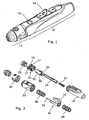
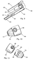
- the lancing device of this embodiment comprises a main housing 10 to the forward end of which is releasably attached a depth adjuster assembly 12.
- a depth adjuster assembly 12 Projecting from the upper surface of the main housing 10 is an externally accessible thumb pad 14 of a slider assembly, the main part lying within the housing.
- the thumb pad 14 is slideable in the reverse direction (away from the depth adjuster assembly) to prime or cock the device prior to use, and further movable forwardly, after use, to release a spent lancet from the front of the housing when the depth adjuster assembly has been removed.
- the device is fired by pressing a firing button 16 which rises proud of the housing when the device is cocked.
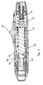
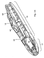
- the main housing 10 is made up of a rear body portion 18 and a front body portion 20 which snap together. Disposed within and acting against a rear inner surface of the rear body portion 18 is a main drive spring 22, the forward end of which is received in a cylindrical recess in the rear part of a lancet holder 24.
- the lancet holder 24 is provided near its forward end with an integral resilient trigger latch finger 26 (visible on an in enlarged scale in Figures 3 and 8 ).
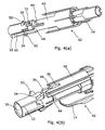
- an L-shaped slot extends down one side of the cylinder and circumferentially so as to provide staggered forward and rearward wall flaps that can be flexed or partially unwrapped to expand the effective internal diameter of the socket 30.
- two cammed abutments 34; 36 project radially from the external wall of the socket, one, 34, being disposed on the forward wall flap and the other, 36, disposed on the smaller, rearward wall flap.
- These abutments 34, 36 are offset with respect to each other, both angularly and longitudinally as shown. They cooperate with a guide slot 38 in a longitudinal projection 40 of a slider assembly 42 of which the thumb pad 14 is an integral part.
- the walls of the projection 40 defining the control slot 38 are also longitudinally staggered, and each include a chamfered gathering surface 44.
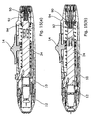
- the slider assembly 42 is constrained for linear sliding movement forward and rearward from the position shown in Figures 1 and 3 against the influence of forward and a rearward bias spring 46, 48 respectively. Shifting the slider assembly forward engages the abutments 34 and 36 simultaneously to cause them to be urged into alignment to pass into the control slot 38. Doing this 'unwraps' the wall portions of the socket partially to expand it to allow a lancet to be loaded or unloaded with minimal insertion or withdrawal force respectively.
- the socket 30 also has external projecting spring seats 50 which seat one end of a compression rebound spring 52, the other end of which is seated in an internal annular shoulder in the front body portion 20.
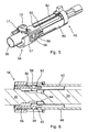
- a trigger moulding 54 Surrounding the forward end of the lancet holder 24 and located in the front body portion 20 against longitudinal movement is a trigger moulding 54 which resiliently carries the firing button 16 through two live hinges 17.
- the trigger moulding has two flexible lock out arms 56 on the outer surfaces of which are two ramp profiles 58.
- the lock out arms 56 are designed to cooperate with respective diametrically opposed slider arms 60, having chamfered leading edges 62.
- the slider arms 60 are an integral part of the slider assembly 42.
- the lancet holder 24 has a reduced width section behind the lancet receiving socket 30, defining two forward facing lock out shoulders 64. Sliding the slider assembly 42 forward from the position shown in Figure 6 causes the slider arms 60 to engage the ramp profiles 58 on the lock out arms 56 to urge them inwardly to the position shown in Figure 7 , where they block forward movement of the lancet holder 24.
- the slider assembly 42 includes in its base a prong or blade element 65 that projects forwardly one side of the projection 40, and which extends beyond the trigger moulding 54 to terminate just rearwardly of the front face of the front body portion 20, when the slider assembly 42 is in its rest position.
- the blade 65 is designed so that the slider assembly 42 cannot be moved forward from its rest position to release a lancet unless the depth adjuster assembly 12 has been removed.
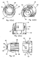
- the depth adjuster 12 is made up of a relatively fixed rear portion 66 that releasably connects to the front end of the front body portion by a snap fit or the like, in a single angular orientation, and which as noted blocks forward movement of the blade 65 when it is attached.
- Inside the rear portion 66 are interrupted, forward facing cam surfaces 61, 63 respectively, that define a helical cam track that functions as a thread.
- An aperture 68 in the rear portion allows indicia 69 on the front depth adjuster portion 70 to be viewed.
- the wall section adjacent said aperture is locally thickened to provide clockwise and anti-clockwise stops 71, 72 to restrict rotation of the front portion 70.
- the cam surfaces 61, 63 alternate and do not overlap in the axial sense and so this means that the rear portion 62 can be moulded which can be opened and closed axially without requiring athreaded mould piece that has to be threaded out of the mould.
- the rear portion 62 also includes an inner cylindrical sleeve 74 which generally surrounds the socket 30 of the lancet holder.
- a detent pip 76 On the outer cylindrical wall of the sleeve is a detent pip 76 with two slots 78 formed to allow resilient flexing of the detent pip.
- the depth adjuster portion 70 comprises a frustoconical form element terminating in a transverse wall 80 with a lancet aperture 82 surrounded by equispaced projections 84, designed to provide a nerve distracting or confusion function.
- the remainder of the front depth adjuster part is internally splined 86 to cooperate with the detent pip 76 on the rear portion to provide a click or detent action as the depth adjuster is rotated.
- On the rear edge of the front portion 70 is formed a cam follower part 88 which is chamfered as seen in Figures 11 and 13 , to allow it to snap past one or more of the cam surfaces 61, 63 on the rear portion 64.
- the front and rear portions 66, 70 of the depth adjuster assembly 12 can be assembled simply by pushing one axially into the other, and no rotation is required.
- the snap action is designed to be sufficiently robust that the two parts cannot readily be separated once assembled.
- the front depth adjuster part can be rotated through approximately 270° with the rotation progressively adjusting the relative axial position thereby to vary the effective penetration depth of the lancing operation.
- the depth adjuster assembly 12 In operation of the device, having set the depth adjuster assembly 12 to give the required penetration, the depth adjuster assembly is removed from the front end of the device and the slider assembly 42 moved forward by thumb pressure on the thumb pad 14 to release a spent lancet (if present) by expanding the socket 30 of the lancet holder due to the action of the abutments 34, 36 being gathered into the slot 38 of the projections 40. Whilst held in the expanded position, a fresh lancet may be located in the lancet holder without requiring any significant axial force. Having inserted the lancet, the slider is allowed to return to its rest position and returning the socket to its non-expanded form, thereby gripping the lancet.
- the depth adjuster assembly 12 is then reapplied to the front of the device and the device cocked by sliding the slider rearwardly.
- the slider assembly engages the lancet holder and pushes it back against the force of the drive spring 22 until the resilient finger 26 snaps rearwardly past the abutment 28 on the housing to latch and in so doing, pushes the trigger button 16 proud.
- the user will then offer the device up to the penetration site and fire the lancet by pressing button 16.
- the thumb pad 14 may be extended forwardly so that, in its rest position, its forward edge lies just to the rear of the aperture in which the trigger button 16 sits.
- the forward and rearward bias springs 46 and 48 that bias the slider assembly may be replaced by integrally moulded spring portions 46 1 , 48 1 , thereby further reducing the component count.
- forward travel of the lancet holder 24 is limited by a forward facing abutment surface on the lancet holder moving into abutment with a rearward facing abutment surface on the housing or a component associated therewith.
- forward travel of the lancet holder 24 is limited by a forward facing abutment surface 90 on a formation 92 at the rear end of the lancet holder 24 engaging a rearward facing shoulder 94 protruding inwardly from the housing wall.
Claims (4)
- Dispositif de lancette ayant :un boîtier (10, 12) ;un support de lancette (24) monté mobile à l'intérieur dudit boîtier, le support de lancette ayant une partie avant pour recevoir, en utilisation, une lancette, etun élément de libération de lancette (40, 42) destiné à être déplacé pour permettre une libération d'une lancette dudit support de lancette,caractérisé par le fait qu'un mouvement dudit élément de libération de lancette (40, 42) pour libérer la lancette entraîne un blocage ou une limitation du mouvement vers l'avant dudit support de lancette.
- Dispositif de lancette selon la revendication 1, dans lequel ledit boîtier (10, 12), ou un composant associé à celui-ci, comprend un élément de retenue de support de lancette (56) mobile entre une position dans laquelle il bloque un mouvement vers l'avant dudit support de lancette (24) et une position libre, dans laquelle un mouvement vers l'avant du support de lancette (24) n'est pas bloqué par celui-ci.
- Dispositif de lancette selon la revendication 2, dans lequel ledit élément de libération de lancette (40, 42) comprend une surface de gouverne (62) qui, à mesure que ledit élément de libération de lancette est déplacé pour libérer la lancette, s'engage avec ledit élément de verrouillage (56) pour un déplacement vers sa position de blocage.
- Dispositif de lancette selon l'une quelconque des revendications 1 à 3, comprenant un agencement de déclenchement (54) actionnable pour s'accrocher à et libérer ledit support de lancette (104) pour réaliser un mouvement sous l'influence d'un ressort d'entraînement, ledit élément de retenue de support de lancette (56) faisant partie dudit agencement de déclenchement (54).
Priority Applications (1)
| Application Number | Priority Date | Filing Date | Title |
|---|---|---|---|
| PL13185802T PL2682056T3 (pl) | 2011-04-08 | 2012-04-04 | Urządzenie do penetracji skóry |
Applications Claiming Priority (3)
| Application Number | Priority Date | Filing Date | Title |
|---|---|---|---|
| US201161473251P | 2011-04-08 | 2011-04-08 | |
| GB1105950.8A GB2489740A (en) | 2011-04-08 | 2011-04-08 | Means for securely retaining a lancet in a lancing device |
| EP12720263.8A EP2677933B1 (fr) | 2011-04-08 | 2012-04-04 | Dispositif de pénétration dans la peau |
Related Parent Applications (3)
| Application Number | Title | Priority Date | Filing Date |
|---|---|---|---|
| EP12720263.8 Division | 2012-04-04 | ||
| EP12720263.8A Division-Into EP2677933B1 (fr) | 2011-04-08 | 2012-04-04 | Dispositif de pénétration dans la peau |
| EP12720263.8A Division EP2677933B1 (fr) | 2011-04-08 | 2012-04-04 | Dispositif de pénétration dans la peau |
Publications (2)
| Publication Number | Publication Date |
|---|---|
| EP2682056A1 EP2682056A1 (fr) | 2014-01-08 |
| EP2682056B1 true EP2682056B1 (fr) | 2015-01-14 |
Family
ID=44072147
Family Applications (5)
| Application Number | Title | Priority Date | Filing Date |
|---|---|---|---|
| EP13185802.9A Active EP2682056B1 (fr) | 2011-04-08 | 2012-04-04 | Dispositif de pénétration de la peau |
| EP16176969.0A Withdrawn EP3100679A1 (fr) | 2011-04-08 | 2012-04-04 | Dispositif pénétrant la peau |
| EP15154913.6A Active EP2907449B1 (fr) | 2011-04-08 | 2012-04-04 | Dispositif de pénétration de la peau |
| EP15159027.0A Active EP2910188B1 (fr) | 2011-04-08 | 2012-04-04 | Dispositif de pénétration de la peau |
| EP12720263.8A Active EP2677933B1 (fr) | 2011-04-08 | 2012-04-04 | Dispositif de pénétration dans la peau |
Family Applications After (4)
| Application Number | Title | Priority Date | Filing Date |
|---|---|---|---|
| EP16176969.0A Withdrawn EP3100679A1 (fr) | 2011-04-08 | 2012-04-04 | Dispositif pénétrant la peau |
| EP15154913.6A Active EP2907449B1 (fr) | 2011-04-08 | 2012-04-04 | Dispositif de pénétration de la peau |
| EP15159027.0A Active EP2910188B1 (fr) | 2011-04-08 | 2012-04-04 | Dispositif de pénétration de la peau |
| EP12720263.8A Active EP2677933B1 (fr) | 2011-04-08 | 2012-04-04 | Dispositif de pénétration dans la peau |
Country Status (10)
| Country | Link |
|---|---|
| US (1) | US9603563B2 (fr) |
| EP (5) | EP2682056B1 (fr) |
| JP (2) | JP6148224B2 (fr) |
| CN (2) | CN103458787B (fr) |
| BR (1) | BR112013025795A2 (fr) |
| GB (1) | GB2489740A (fr) |
| IN (1) | IN2014DN01836A (fr) |
| MX (1) | MX338788B (fr) |
| PL (4) | PL2677933T3 (fr) |
| WO (1) | WO2012137001A1 (fr) |
Families Citing this family (8)
| Publication number | Priority date | Publication date | Assignee | Title |
|---|---|---|---|---|
| US20140214065A1 (en) * | 2013-01-29 | 2014-07-31 | Yong Pil Kim | Blood lancet device |
| TW201513832A (zh) * | 2013-10-11 | 2015-04-16 | Ysp Co Ltd | 採血裝置及其採血針與採血筆 |
| USD758566S1 (en) * | 2014-03-17 | 2016-06-07 | Erik Chen | Blood sampling pen |
| USD774641S1 (en) * | 2015-11-11 | 2016-12-20 | Merck Sharp & Dohme Corp. | Auto injector |
| US20180015224A1 (en) | 2016-07-13 | 2018-01-18 | California Institute Of Technology | Dampers and Methods for Performing Measurements in an Autoinjector |
| KR102090541B1 (ko) * | 2017-09-29 | 2020-05-27 | 최임철 | 가압-작동식 일회용 무통 채혈기 |
| CN108982604A (zh) * | 2018-08-04 | 2018-12-11 | 北京怡成生物电子技术股份有限公司 | 一种动态连续测定体液中分析物的便携式监测系统 |
| CN115475324A (zh) * | 2021-06-16 | 2022-12-16 | 苏州悦肤达医疗科技有限公司 | 一种助针器及医用装置 |
Family Cites Families (70)
| Publication number | Priority date | Publication date | Assignee | Title |
|---|---|---|---|---|
| US4976724A (en) | 1989-08-25 | 1990-12-11 | Lifescan, Inc. | Lancet ejector mechanism |
| WO1993009723A1 (fr) | 1991-11-12 | 1993-05-27 | Ramel Urs A | Dispositif a lancette |
| US5282822A (en) | 1993-01-19 | 1994-02-01 | Sherwood Medical Company | Lancet ejector for lancet injector |
| US5464418A (en) | 1993-12-09 | 1995-11-07 | Schraga; Steven | Reusable lancet device |
| AUPN689695A0 (en) | 1995-12-01 | 1995-12-21 | Brakey, Dale Robert | Blood letting device |
| US5613978A (en) * | 1996-06-04 | 1997-03-25 | Palco Laboratories | Adjustable tip for lancet device |
| GB9616953D0 (en) * | 1996-08-13 | 1996-09-25 | Owen Mumford Ltd | Improvements relating to skin prickers |
| US5916230A (en) * | 1997-06-16 | 1999-06-29 | Bayer Corporation | Blood sampling device with adjustable end cap |
| US6949111B2 (en) | 1998-02-13 | 2005-09-27 | Steven Schraga | Lancet device |
| US6022366A (en) | 1998-06-11 | 2000-02-08 | Stat Medical Devices Inc. | Lancet having adjustable penetration depth |
| US6346114B1 (en) | 1998-06-11 | 2002-02-12 | Stat Medical Devices, Inc. | Adjustable length member such as a cap of a lancet device for adjusting penetration depth |
| US6197040B1 (en) * | 1999-02-23 | 2001-03-06 | Lifescan, Inc. | Lancing device having a releasable connector |
| US6558402B1 (en) * | 1999-08-03 | 2003-05-06 | Becton, Dickinson And Company | Lancer |
| US6283982B1 (en) * | 1999-10-19 | 2001-09-04 | Facet Technologies, Inc. | Lancing device and method of sample collection |
| US6322575B1 (en) | 2000-01-05 | 2001-11-27 | Steven Schraga | Lancet depth adjustment assembly |
| DE10053974A1 (de) | 2000-10-31 | 2002-05-29 | Roche Diagnostics Gmbh | System zur Blutentnahme |
| EP1358844B1 (fr) | 2001-01-12 | 2010-09-01 | ARKRAY, Inc. | Dispositif de perforation |
| GB0103977D0 (en) | 2001-02-17 | 2001-04-04 | Owen Mumford Ltd | Improvements relating to skin prickers |
| CA2450711C (fr) | 2001-06-13 | 2010-11-02 | Steven Schraga | Dispositif a lancette a usage unique |
| CN1267056C (zh) | 2001-07-11 | 2006-08-02 | 爱科来株式会社 | 穿刺装置 |
| DE20114658U1 (de) | 2001-09-05 | 2001-11-15 | Wilden Engineering Und Vertrie | Lanzette für die Blutentnahme |
| US6645219B2 (en) | 2001-09-07 | 2003-11-11 | Amira Medical | Rotatable penetration depth adjusting arrangement |
| US20030100913A1 (en) | 2001-10-09 | 2003-05-29 | Guoping Shi | Depth adjustable cap of lancing device |
| US20040098010A1 (en) * | 2001-10-22 | 2004-05-20 | Glenn Davison | Confuser crown skin pricker |
| JP4257943B2 (ja) | 2002-07-29 | 2009-04-30 | アークレイ株式会社 | 穿刺用ユニット、および穿刺用部材の取り外し具 |
| US6852119B1 (en) | 2002-09-09 | 2005-02-08 | Ramzi F. Abulhaj | Adjustable disposable lancet and method |
| EP1614383B1 (fr) | 2003-04-16 | 2017-03-15 | ARKRAY, Inc. | Dispositif de perforation |
| JP4761701B2 (ja) * | 2003-05-21 | 2011-08-31 | アークレイ株式会社 | 穿刺深さを調整可能な穿刺装置 |
| US7905898B2 (en) | 2003-08-15 | 2011-03-15 | Stat Medical Devices, Inc. | Adjustable lancet device and method |
| WO2005034753A1 (fr) | 2003-10-15 | 2005-04-21 | Surgilance Pte Ltd | Ensemble lancette |
| EP1708610A1 (fr) | 2004-01-12 | 2006-10-11 | Minnesota Scientific, Inc. | Appareil pour retenir des ecarteurs manuels |
| US20050159768A1 (en) | 2004-01-15 | 2005-07-21 | Home Diagnostics, Inc. | Lancing device |
| WO2005089333A2 (fr) | 2004-03-15 | 2005-09-29 | Oakville Hong Kong Company Limited | Dispositif a lancette et son procede d'utilisation |
| US7670352B1 (en) | 2004-03-24 | 2010-03-02 | Caribbean Medical Brokers, Inc. | Adjustable tip with integrated detent for blood lancet system |
| US7955347B2 (en) | 2004-06-25 | 2011-06-07 | Facet Technologies, Llc | Low cost safety lancet |
| GB2421439B (en) | 2004-12-21 | 2009-07-29 | Owen Mumford Ltd | Skin pricking apparatus |
| DE602006015462D1 (de) * | 2005-03-04 | 2010-08-26 | Bayer Healthcare Llc | Lanzettenauslösungsmechanismus |
| WO2006107914A2 (fr) * | 2005-04-04 | 2006-10-12 | Facet Technologies, Llc | Dispositif de lancette a profil etroit |
| US20060247670A1 (en) * | 2005-05-02 | 2006-11-02 | Levaughn Richard W | Lancing device with automatic lancet release |
| US20070083222A1 (en) | 2005-06-16 | 2007-04-12 | Stat Medical Devices, Inc. | Lancet device, removal system for lancet device, and method |
| EP1992285A4 (fr) | 2006-03-08 | 2011-12-28 | Arkray Inc | Dispositif a lancette |
| CN101400302B (zh) * | 2006-03-10 | 2010-11-03 | 爱科来株式会社 | 刺血针装置 |
| EP2010055B1 (fr) | 2006-04-25 | 2018-01-10 | Facet Technologies, LLC | Autopiqueur comportant un mécanisme central d'entraînement indépendant |
| EP2016900B8 (fr) | 2006-05-10 | 2018-08-29 | PHC Holdings Corporation | Instrument de percée et cartouche d'aiguille à perforer |
| US7955348B2 (en) | 2006-06-15 | 2011-06-07 | Abbott Diabetes Care Inc. | Lancing devices and methods |
| JP4997247B2 (ja) | 2006-09-29 | 2012-08-08 | テルモ株式会社 | 使い捨てカートリッジ |
| US8043318B2 (en) | 2007-02-08 | 2011-10-25 | Stat Medical Devices, Inc. | Push-button lance device and method |
| EP2144563B1 (fr) | 2007-03-12 | 2016-05-18 | Ascensia Diabetes Care Holdings AG | Mécanisme d'éjection de lancette |
| KR100820523B1 (ko) | 2007-03-14 | 2008-04-08 | 홍관호 | 채혈기 |
| US8469986B2 (en) | 2007-03-30 | 2013-06-25 | Stat Medical Devices, Inc. | Lancet device with combined trigger and cocking mechanism and method |
| WO2008157610A1 (fr) | 2007-06-19 | 2008-12-24 | Stat Medical Devices, Inc. | Dispositif de lancette avec ajustement de profondeur et système d'extraction de lancette et procédé |
| GB0715803D0 (en) * | 2007-08-14 | 2007-09-26 | Owen Mumford Ltd | Lancing devices |
| GB2451840B (en) * | 2007-08-14 | 2012-01-18 | Owen Mumford Ltd | Lancing devices |
| GB0715798D0 (en) * | 2007-08-14 | 2007-09-19 | Owen Mumford Ltd | Lancing devices |
| JPWO2009035084A1 (ja) | 2007-09-12 | 2010-12-24 | 泉株式会社 | ランセットアッセンブリ |
| EP2050393B1 (fr) | 2007-10-19 | 2011-04-13 | Bionime Corporation | Dispositif de lancement |
| CN101877997B (zh) | 2007-11-27 | 2012-07-25 | 爱科来株式会社 | 穿刺装置 |
| CN201104887Y (zh) * | 2007-12-05 | 2008-08-27 | 成都瑞琦科技实业有限责任公司 | 新型静脉采血针 |
| US8932314B2 (en) | 2008-05-09 | 2015-01-13 | Lifescan Scotland Limited | Prime and fire lancing device with contacting bias drive and method |
| US8454533B2 (en) | 2008-05-09 | 2013-06-04 | Lifescan Scotland Limited | Lancing devices and methods |
| US20090281457A1 (en) * | 2008-05-09 | 2009-11-12 | Lifescan Soctland Ltd. | Prime and fire lancing device with non-contacting bias drive and method |
| WO2009148431A1 (fr) | 2008-06-05 | 2009-12-10 | Bayer Healthcare Llc | Dispositif autopiqueur |
| US8123772B2 (en) | 2008-08-14 | 2012-02-28 | Abbott Diabetes Care Inc. | Cap for lancing device with adjustable mode of operation |
| US20100049233A1 (en) | 2008-08-25 | 2010-02-25 | Abbott Diabetes Care Inc. | Lancet having integrated drive mechanism |
| EP2174591B1 (fr) | 2008-10-09 | 2019-01-16 | Roche Diabetes Care GmbH | Appareil de perçage |
| US8568434B2 (en) | 2008-10-14 | 2013-10-29 | Bionime Corporation | Lancing device |
| KR20110096147A (ko) | 2008-12-04 | 2011-08-29 | 벤처 코포레이션 리미티드 | 절개 디바이스 |
| WO2010080584A1 (fr) | 2008-12-18 | 2010-07-15 | Facet Technologies, Llc | Autopiqueur et lancette |
| CN101444428B (zh) | 2008-12-30 | 2010-04-07 | 苏州施莱医疗器械有限公司 | 安全便捷式一次性自动采血针 |
| US8317812B2 (en) * | 2009-07-29 | 2012-11-27 | Wah Leong Lum | Lancet device with lance retraction |
-
2011
- 2011-04-08 GB GB1105950.8A patent/GB2489740A/en not_active Withdrawn
-
2012
- 2012-04-04 EP EP13185802.9A patent/EP2682056B1/fr active Active
- 2012-04-04 WO PCT/GB2012/050761 patent/WO2012137001A1/fr active Application Filing
- 2012-04-04 PL PL12720263T patent/PL2677933T3/pl unknown
- 2012-04-04 BR BR112013025795A patent/BR112013025795A2/pt not_active IP Right Cessation
- 2012-04-04 CN CN201280015833.4A patent/CN103458787B/zh active Active
- 2012-04-04 EP EP16176969.0A patent/EP3100679A1/fr not_active Withdrawn
- 2012-04-04 JP JP2014503214A patent/JP6148224B2/ja active Active
- 2012-04-04 EP EP15154913.6A patent/EP2907449B1/fr active Active
- 2012-04-04 EP EP15159027.0A patent/EP2910188B1/fr active Active
- 2012-04-04 US US14/110,526 patent/US9603563B2/en active Active
- 2012-04-04 PL PL13185802T patent/PL2682056T3/pl unknown
- 2012-04-04 CN CN201510557882.6A patent/CN105105765B/zh active Active
- 2012-04-04 MX MX2013011649A patent/MX338788B/es active IP Right Grant
- 2012-04-04 PL PL15159027.0T patent/PL2910188T3/pl unknown
- 2012-04-04 IN IN1836DEN2014 patent/IN2014DN01836A/en unknown
- 2012-04-04 PL PL15154913T patent/PL2907449T3/pl unknown
- 2012-04-04 EP EP12720263.8A patent/EP2677933B1/fr active Active
-
2017
- 2017-02-16 JP JP2017026684A patent/JP2017113588A/ja active Pending
Also Published As
| Publication number | Publication date |
|---|---|
| BR112013025795A2 (pt) | 2016-12-27 |
| IN2014DN01836A (fr) | 2015-05-15 |
| CN105105765B (zh) | 2018-04-24 |
| US9603563B2 (en) | 2017-03-28 |
| PL2910188T3 (pl) | 2016-11-30 |
| CN103458787A (zh) | 2013-12-18 |
| JP2017113588A (ja) | 2017-06-29 |
| GB2489740A (en) | 2012-10-10 |
| MX338788B (es) | 2016-05-02 |
| EP2682056A1 (fr) | 2014-01-08 |
| GB201105950D0 (en) | 2011-05-18 |
| EP2677933B1 (fr) | 2015-06-10 |
| EP2907449B1 (fr) | 2016-11-30 |
| JP2014512908A (ja) | 2014-05-29 |
| CN103458787B (zh) | 2015-09-09 |
| PL2682056T3 (pl) | 2015-08-31 |
| JP6148224B2 (ja) | 2017-06-14 |
| EP2677933A1 (fr) | 2014-01-01 |
| EP2907449A2 (fr) | 2015-08-19 |
| EP2907449A3 (fr) | 2015-11-18 |
| PL2907449T3 (pl) | 2017-05-31 |
| WO2012137001A1 (fr) | 2012-10-11 |
| CN105105765A (zh) | 2015-12-02 |
| PL2677933T3 (pl) | 2015-11-30 |
| US20140121691A1 (en) | 2014-05-01 |
| EP3100679A1 (fr) | 2016-12-07 |
| EP2910188A1 (fr) | 2015-08-26 |
| EP2910188B1 (fr) | 2016-06-01 |
| MX2013011649A (es) | 2013-11-01 |
Similar Documents
| Publication | Publication Date | Title |
|---|---|---|
| EP2682056B1 (fr) | Dispositif de pénétration de la peau | |
| EP3030287B1 (fr) | Unité motrice | |
| EP2185073B1 (fr) | Dispositifs auto-piqueurs | |
| JP5074397B2 (ja) | 針のカバーアセンブリ及び針先アセンブリと共に使用する把持リング | |
| JP4847316B2 (ja) | 注射器用の針の保護装置及び注射器と針の保護装置とを備えた注射器具 | |
| JP2009506816A5 (fr) | ||
| JP2014503287A (ja) | 発射位置に向かうトリガ部品の移動に対する抵抗力を提供する接触面を有する自動注入装置 | |
| EP3154611B1 (fr) | Segments de piston mécanisme d'entraînement pour un dispositif d'administration de médicament | |
| EP3323448A1 (fr) | Dispositifs d'administration de médicaments | |
| WO2011084103A1 (fr) | Lancette | |
| EP3380156B1 (fr) | Dispositif d'administration de médicament | |
| EP4299090A1 (fr) | Auto-injecteur avec moyens de reglage resiliants entre la tige et le recipient | |
| WO2023198566A1 (fr) | Auto-injecteur pour injection automatique d'un produit dans un point de piqûre |
Legal Events
| Date | Code | Title | Description |
|---|---|---|---|
| PUAI | Public reference made under article 153(3) epc to a published international application that has entered the european phase |
Free format text: ORIGINAL CODE: 0009012 |
|
| 17P | Request for examination filed |
Effective date: 20131004 |
|
| AC | Divisional application: reference to earlier application |
Ref document number: 2677933 Country of ref document: EP Kind code of ref document: P |
|
| AK | Designated contracting states |
Kind code of ref document: A1 Designated state(s): AL AT BE BG CH CY CZ DE DK EE ES FI FR GB GR HR HU IE IS IT LI LT LU LV MC MK MT NL NO PL PT RO RS SE SI SK SM TR |
|
| GRAP | Despatch of communication of intention to grant a patent |
Free format text: ORIGINAL CODE: EPIDOSNIGR1 |
|
| INTG | Intention to grant announced |
Effective date: 20140807 |
|
| GRAS | Grant fee paid |
Free format text: ORIGINAL CODE: EPIDOSNIGR3 |
|
| GRAA | (expected) grant |
Free format text: ORIGINAL CODE: 0009210 |
|
| AC | Divisional application: reference to earlier application |
Ref document number: 2677933 Country of ref document: EP Kind code of ref document: P |
|
| AK | Designated contracting states |
Kind code of ref document: B1 Designated state(s): AL AT BE BG CH CY CZ DE DK EE ES FI FR GB GR HR HU IE IS IT LI LT LU LV MC MK MT NL NO PL PT RO RS SE SI SK SM TR |
|
| REG | Reference to a national code |
Ref country code: GB Ref legal event code: FG4D |
|
| REG | Reference to a national code |
Ref country code: CH Ref legal event code: EP |
|
| REG | Reference to a national code |
Ref country code: IE Ref legal event code: FG4D |
|
| REG | Reference to a national code |
Ref country code: AT Ref legal event code: REF Ref document number: 706574 Country of ref document: AT Kind code of ref document: T Effective date: 20150215 |
|
| REG | Reference to a national code |
Ref country code: DE Ref legal event code: R096 Ref document number: 602012004977 Country of ref document: DE Effective date: 20150226 |
|
| REG | Reference to a national code |
Ref country code: CH Ref legal event code: NV Representative=s name: CRONIN INTELLECTUAL PROPERTY, CH |
|
| REG | Reference to a national code |
Ref country code: NL Ref legal event code: VDEP Effective date: 20150114 |
|
| REG | Reference to a national code |
Ref country code: AT Ref legal event code: MK05 Ref document number: 706574 Country of ref document: AT Kind code of ref document: T Effective date: 20150114 |
|
| REG | Reference to a national code |
Ref country code: LT Ref legal event code: MG4D |
|
| PG25 | Lapsed in a contracting state [announced via postgrant information from national office to epo] |
Ref country code: LT Free format text: LAPSE BECAUSE OF FAILURE TO SUBMIT A TRANSLATION OF THE DESCRIPTION OR TO PAY THE FEE WITHIN THE PRESCRIBED TIME-LIMIT Effective date: 20150114 Ref country code: ES Free format text: LAPSE BECAUSE OF FAILURE TO SUBMIT A TRANSLATION OF THE DESCRIPTION OR TO PAY THE FEE WITHIN THE PRESCRIBED TIME-LIMIT Effective date: 20150114 Ref country code: HR Free format text: LAPSE BECAUSE OF FAILURE TO SUBMIT A TRANSLATION OF THE DESCRIPTION OR TO PAY THE FEE WITHIN THE PRESCRIBED TIME-LIMIT Effective date: 20150114 Ref country code: BG Free format text: LAPSE BECAUSE OF FAILURE TO SUBMIT A TRANSLATION OF THE DESCRIPTION OR TO PAY THE FEE WITHIN THE PRESCRIBED TIME-LIMIT Effective date: 20150414 Ref country code: SE Free format text: LAPSE BECAUSE OF FAILURE TO SUBMIT A TRANSLATION OF THE DESCRIPTION OR TO PAY THE FEE WITHIN THE PRESCRIBED TIME-LIMIT Effective date: 20150114 Ref country code: NO Free format text: LAPSE BECAUSE OF FAILURE TO SUBMIT A TRANSLATION OF THE DESCRIPTION OR TO PAY THE FEE WITHIN THE PRESCRIBED TIME-LIMIT Effective date: 20150414 Ref country code: FI Free format text: LAPSE BECAUSE OF FAILURE TO SUBMIT A TRANSLATION OF THE DESCRIPTION OR TO PAY THE FEE WITHIN THE PRESCRIBED TIME-LIMIT Effective date: 20150114 |
|
| PG25 | Lapsed in a contracting state [announced via postgrant information from national office to epo] |
Ref country code: IS Free format text: LAPSE BECAUSE OF FAILURE TO SUBMIT A TRANSLATION OF THE DESCRIPTION OR TO PAY THE FEE WITHIN THE PRESCRIBED TIME-LIMIT Effective date: 20150514 Ref country code: LV Free format text: LAPSE BECAUSE OF FAILURE TO SUBMIT A TRANSLATION OF THE DESCRIPTION OR TO PAY THE FEE WITHIN THE PRESCRIBED TIME-LIMIT Effective date: 20150114 Ref country code: AT Free format text: LAPSE BECAUSE OF FAILURE TO SUBMIT A TRANSLATION OF THE DESCRIPTION OR TO PAY THE FEE WITHIN THE PRESCRIBED TIME-LIMIT Effective date: 20150114 Ref country code: NL Free format text: LAPSE BECAUSE OF FAILURE TO SUBMIT A TRANSLATION OF THE DESCRIPTION OR TO PAY THE FEE WITHIN THE PRESCRIBED TIME-LIMIT Effective date: 20150114 Ref country code: GR Free format text: LAPSE BECAUSE OF FAILURE TO SUBMIT A TRANSLATION OF THE DESCRIPTION OR TO PAY THE FEE WITHIN THE PRESCRIBED TIME-LIMIT Effective date: 20150415 Ref country code: RS Free format text: LAPSE BECAUSE OF FAILURE TO SUBMIT A TRANSLATION OF THE DESCRIPTION OR TO PAY THE FEE WITHIN THE PRESCRIBED TIME-LIMIT Effective date: 20150114 |
|
| REG | Reference to a national code |
Ref country code: PL Ref legal event code: T3 |
|
| REG | Reference to a national code |
Ref country code: DE Ref legal event code: R097 Ref document number: 602012004977 Country of ref document: DE |
|
| PG25 | Lapsed in a contracting state [announced via postgrant information from national office to epo] |
Ref country code: EE Free format text: LAPSE BECAUSE OF FAILURE TO SUBMIT A TRANSLATION OF THE DESCRIPTION OR TO PAY THE FEE WITHIN THE PRESCRIBED TIME-LIMIT Effective date: 20150114 Ref country code: DK Free format text: LAPSE BECAUSE OF FAILURE TO SUBMIT A TRANSLATION OF THE DESCRIPTION OR TO PAY THE FEE WITHIN THE PRESCRIBED TIME-LIMIT Effective date: 20150114 Ref country code: SK Free format text: LAPSE BECAUSE OF FAILURE TO SUBMIT A TRANSLATION OF THE DESCRIPTION OR TO PAY THE FEE WITHIN THE PRESCRIBED TIME-LIMIT Effective date: 20150114 Ref country code: CZ Free format text: LAPSE BECAUSE OF FAILURE TO SUBMIT A TRANSLATION OF THE DESCRIPTION OR TO PAY THE FEE WITHIN THE PRESCRIBED TIME-LIMIT Effective date: 20150114 Ref country code: RO Free format text: LAPSE BECAUSE OF FAILURE TO SUBMIT A TRANSLATION OF THE DESCRIPTION OR TO PAY THE FEE WITHIN THE PRESCRIBED TIME-LIMIT Effective date: 20150114 |
|
| PLBE | No opposition filed within time limit |
Free format text: ORIGINAL CODE: 0009261 |
|
| STAA | Information on the status of an ep patent application or granted ep patent |
Free format text: STATUS: NO OPPOSITION FILED WITHIN TIME LIMIT |
|
| PG25 | Lapsed in a contracting state [announced via postgrant information from national office to epo] |
Ref country code: MC Free format text: LAPSE BECAUSE OF FAILURE TO SUBMIT A TRANSLATION OF THE DESCRIPTION OR TO PAY THE FEE WITHIN THE PRESCRIBED TIME-LIMIT Effective date: 20150114 Ref country code: LU Free format text: LAPSE BECAUSE OF FAILURE TO SUBMIT A TRANSLATION OF THE DESCRIPTION OR TO PAY THE FEE WITHIN THE PRESCRIBED TIME-LIMIT Effective date: 20150404 |
|
| 26N | No opposition filed |
Effective date: 20151015 |
|
| PG25 | Lapsed in a contracting state [announced via postgrant information from national office to epo] |
Ref country code: IT Free format text: LAPSE BECAUSE OF FAILURE TO SUBMIT A TRANSLATION OF THE DESCRIPTION OR TO PAY THE FEE WITHIN THE PRESCRIBED TIME-LIMIT Effective date: 20150114 |
|
| REG | Reference to a national code |
Ref country code: IE Ref legal event code: MM4A |
|
| PG25 | Lapsed in a contracting state [announced via postgrant information from national office to epo] |
Ref country code: SI Free format text: LAPSE BECAUSE OF FAILURE TO SUBMIT A TRANSLATION OF THE DESCRIPTION OR TO PAY THE FEE WITHIN THE PRESCRIBED TIME-LIMIT Effective date: 20150114 |
|
| REG | Reference to a national code |
Ref country code: FR Ref legal event code: PLFP Year of fee payment: 5 |
|
| PG25 | Lapsed in a contracting state [announced via postgrant information from national office to epo] |
Ref country code: IE Free format text: LAPSE BECAUSE OF NON-PAYMENT OF DUE FEES Effective date: 20150404 |
|
| PG25 | Lapsed in a contracting state [announced via postgrant information from national office to epo] |
Ref country code: BE Free format text: LAPSE BECAUSE OF FAILURE TO SUBMIT A TRANSLATION OF THE DESCRIPTION OR TO PAY THE FEE WITHIN THE PRESCRIBED TIME-LIMIT Effective date: 20150114 |
|
| PG25 | Lapsed in a contracting state [announced via postgrant information from national office to epo] |
Ref country code: MT Free format text: LAPSE BECAUSE OF FAILURE TO SUBMIT A TRANSLATION OF THE DESCRIPTION OR TO PAY THE FEE WITHIN THE PRESCRIBED TIME-LIMIT Effective date: 20150114 |
|
| REG | Reference to a national code |
Ref country code: FR Ref legal event code: PLFP Year of fee payment: 6 |
|
| PG25 | Lapsed in a contracting state [announced via postgrant information from national office to epo] |
Ref country code: HU Free format text: LAPSE BECAUSE OF FAILURE TO SUBMIT A TRANSLATION OF THE DESCRIPTION OR TO PAY THE FEE WITHIN THE PRESCRIBED TIME-LIMIT; INVALID AB INITIO Effective date: 20120404 Ref country code: SM Free format text: LAPSE BECAUSE OF FAILURE TO SUBMIT A TRANSLATION OF THE DESCRIPTION OR TO PAY THE FEE WITHIN THE PRESCRIBED TIME-LIMIT Effective date: 20150114 |
|
| PGFP | Annual fee paid to national office [announced via postgrant information from national office to epo] |
Ref country code: PL Payment date: 20170330 Year of fee payment: 6 |
|
| PG25 | Lapsed in a contracting state [announced via postgrant information from national office to epo] |
Ref country code: CY Free format text: LAPSE BECAUSE OF FAILURE TO SUBMIT A TRANSLATION OF THE DESCRIPTION OR TO PAY THE FEE WITHIN THE PRESCRIBED TIME-LIMIT Effective date: 20150114 |
|
| PG25 | Lapsed in a contracting state [announced via postgrant information from national office to epo] |
Ref country code: PT Free format text: LAPSE BECAUSE OF FAILURE TO SUBMIT A TRANSLATION OF THE DESCRIPTION OR TO PAY THE FEE WITHIN THE PRESCRIBED TIME-LIMIT Effective date: 20150514 |
|
| PG25 | Lapsed in a contracting state [announced via postgrant information from national office to epo] |
Ref country code: TR Free format text: LAPSE BECAUSE OF FAILURE TO SUBMIT A TRANSLATION OF THE DESCRIPTION OR TO PAY THE FEE WITHIN THE PRESCRIBED TIME-LIMIT Effective date: 20150114 |
|
| REG | Reference to a national code |
Ref country code: FR Ref legal event code: PLFP Year of fee payment: 7 |
|
| REG | Reference to a national code |
Ref country code: CH Ref legal event code: PCAR Free format text: NEW ADDRESS: CHEMIN DE LA VUARPILLIERE 29, 1260 NYON (CH) |
|
| PG25 | Lapsed in a contracting state [announced via postgrant information from national office to epo] |
Ref country code: MK Free format text: LAPSE BECAUSE OF FAILURE TO SUBMIT A TRANSLATION OF THE DESCRIPTION OR TO PAY THE FEE WITHIN THE PRESCRIBED TIME-LIMIT Effective date: 20150114 |
|
| PG25 | Lapsed in a contracting state [announced via postgrant information from national office to epo] |
Ref country code: AL Free format text: LAPSE BECAUSE OF FAILURE TO SUBMIT A TRANSLATION OF THE DESCRIPTION OR TO PAY THE FEE WITHIN THE PRESCRIBED TIME-LIMIT Effective date: 20150114 |
|
| REG | Reference to a national code |
Ref country code: CH Ref legal event code: PL |
|
| PG25 | Lapsed in a contracting state [announced via postgrant information from national office to epo] |
Ref country code: LI Free format text: LAPSE BECAUSE OF NON-PAYMENT OF DUE FEES Effective date: 20180430 Ref country code: CH Free format text: LAPSE BECAUSE OF NON-PAYMENT OF DUE FEES Effective date: 20180430 |
|
| PG25 | Lapsed in a contracting state [announced via postgrant information from national office to epo] |
Ref country code: PL Free format text: LAPSE BECAUSE OF NON-PAYMENT OF DUE FEES Effective date: 20180404 |
|
| P01 | Opt-out of the competence of the unified patent court (upc) registered |
Effective date: 20230530 |
|
| PGFP | Annual fee paid to national office [announced via postgrant information from national office to epo] |
Ref country code: FR Payment date: 20230420 Year of fee payment: 12 Ref country code: DE Payment date: 20230420 Year of fee payment: 12 |
|
| PGFP | Annual fee paid to national office [announced via postgrant information from national office to epo] |
Ref country code: GB Payment date: 20230419 Year of fee payment: 12 |
|
| REG | Reference to a national code |
Ref country code: DE Ref legal event code: R082 Ref document number: 602012004977 Country of ref document: DE Representative=s name: KANDLBINDER, MARKUS, DIPL.-PHYS., DE |