EP2680773B1 - Zange zum schneiden von werkstücken - Google Patents
Zange zum schneiden von werkstücken Download PDFInfo
- Publication number
- EP2680773B1 EP2680773B1 EP12711359.5A EP12711359A EP2680773B1 EP 2680773 B1 EP2680773 B1 EP 2680773B1 EP 12711359 A EP12711359 A EP 12711359A EP 2680773 B1 EP2680773 B1 EP 2680773B1
- Authority
- EP
- European Patent Office
- Prior art keywords
- pliers
- cutting
- leg
- jaw
- pressure
- Prior art date
- Legal status (The legal status is an assumption and is not a legal conclusion. Google has not performed a legal analysis and makes no representation as to the accuracy of the status listed.)
- Not-in-force
Links
Images


Classifications
-
- B—PERFORMING OPERATIONS; TRANSPORTING
- B23—MACHINE TOOLS; METAL-WORKING NOT OTHERWISE PROVIDED FOR
- B23D—PLANING; SLOTTING; SHEARING; BROACHING; SAWING; FILING; SCRAPING; LIKE OPERATIONS FOR WORKING METAL BY REMOVING MATERIAL, NOT OTHERWISE PROVIDED FOR
- B23D29/00—Hand-held metal-shearing or metal-cutting devices
- B23D29/02—Hand-operated metal-shearing devices
- B23D29/023—Hand-operated metal-shearing devices for cutting wires
-
- A—HUMAN NECESSITIES
- A61—MEDICAL OR VETERINARY SCIENCE; HYGIENE
- A61B—DIAGNOSIS; SURGERY; IDENTIFICATION
- A61B17/00—Surgical instruments, devices or methods
- A61B17/56—Surgical instruments or methods for treatment of bones or joints; Devices specially adapted therefor
- A61B17/58—Surgical instruments or methods for treatment of bones or joints; Devices specially adapted therefor for osteosynthesis, e.g. bone plates, screws or setting implements
- A61B17/88—Osteosynthesis instruments; Methods or means for implanting or extracting internal or external fixation devices
- A61B17/8863—Apparatus for shaping or cutting osteosynthesis equipment by medical personnel
-
- B—PERFORMING OPERATIONS; TRANSPORTING
- B25—HAND TOOLS; PORTABLE POWER-DRIVEN TOOLS; MANIPULATORS
- B25B—TOOLS OR BENCH DEVICES NOT OTHERWISE PROVIDED FOR, FOR FASTENING, CONNECTING, DISENGAGING, OR HOLDING
- B25B7/00—Pliers; Other hand-held gripping tools with jaws on pivoted limbs; Details applicable generally to pivoted-limb hand tools
- B25B7/12—Pliers; Other hand-held gripping tools with jaws on pivoted limbs; Details applicable generally to pivoted-limb hand tools involving special transmission means between the handles and the jaws, e.g. toggle levers, gears
-
- B—PERFORMING OPERATIONS; TRANSPORTING
- B26—HAND CUTTING TOOLS; CUTTING; SEVERING
- B26B—HAND-HELD CUTTING TOOLS NOT OTHERWISE PROVIDED FOR
- B26B17/00—Hand cutting tools, i.e. with the cutting action actuated by muscle power with two jaws which come into abutting contact
- B26B17/02—Hand cutting tools, i.e. with the cutting action actuated by muscle power with two jaws which come into abutting contact with jaws operated indirectly by the handles, e.g. through cams or toggle levers
Definitions
- the invention relates to a pair of pliers for cutting workpieces, in particular made of metal with at least one pliers leg and a pressure element, which are interconnected via a pivot point, wherein the pliers leg forms a pliers mouth for receiving the workpiece and the pliers leg is associated with a cutting jaw and the Cutting element is arranged rotatably relative to the pliers leg by means of a latching device about a pivot point, wherein the cutting element opposite of the cutting jaw has a latching tooth and the latching tooth with a rack of a pressure piece engages the pressure piece or the rack by means of a force storage device in engagement with the latching toothing is held, wherein the detent toothing is assigned a lock with a further locking bar.
- Pliers are known in a variety of designs and on the market. In the present case, it is all about special pliers for cutting workpieces in trauma surgery. They are z. B. in orthopedics for clamping wires, nails or screw elements needed. The prevention of chips od. Like. Particles in the separation process a hygienic necessity to avoid infections. In the osteo-osteosynthesis of operative fracture treatment, bone fragments are connected with wires, usually with so-called "Kirschner" wires. For cutting these wires side cutters or similar tools are used, but also brings with it the risk of material residues. In addition, considerable forces must be applied to the pliers to cut the appropriate wire.
- Such medical or surgical forceps are for example from the EP 0 321 884 known. With this wire tongs a wire is squeezed off, which requires considerable force. The same applies to the pliers after the DE 43 29 220 A1 ,
- a pair of pliers having the features of the preamble of claim 1 is known from DE 33 02 875 A1 known.
- Object of the present invention is for a pliers o. G. To develop type, which is to be operated with one hand and does not require a great deal of effort, but also leads to no material removal, which can be left behind.
- the pressure piece is supported with a round piece in a trough in the pressure element and the lock is slidably disposed in the pliers legs.
- This locking device is of particular importance. By their operation of the required effort is significantly reduced.
- the actuation of the locking device is also not continuous, but preferably quasi by pumping pliers legs or pressure element against the: pliers legs.
- the pliers leg is associated with a cutting element with a cutting jaw, wherein a base of the pliers mouth and a bottom of the cutting jaw are arranged near a pivot about which rotates the cutting element in the pliers legs.
- the wire is not squeezed off, but actually cut.
- the cutting element rotates around the fulcrum and thereby cuts with a cutting edge into the workpiece, so that after completion of the Rotation is actually cut off. On the one hand, this avoids that chips od. Like., To arise, on the other hand, the force is reduced.
- the pliers limb is associated with a cutting element with a cutting jaw, wherein forceps jaw and cutting jaw are matched in their contours and rotates the cutting element in a roller cage in the pliers legs.
- the cutting element opposite to the cutting jaw has a latching toothing.
- This detent toothing cooperates with a toothed bar of a pressure piece, wherein this pressure piece is actuated by the pressure element.
- the pressure piece is supported by a round piece in a depression in the pressure element.
- the pressure piece or the rack remains in engagement with the latching tooth, the pressure piece is still associated with a corresponding force storage, which presses on the pressure piece so that the rack is in engagement with the latching toothing.
- a lock is still provided, which holds the cutting element in the already achieved rotational position when the pressure piece is tracked.
- the lock also has a locking bar, which engages in the latching toothing of the cutting element.
- the lock is slidably disposed in the pliers leg.
- the pressure element is preferably formed thigh-like and has a pivot-like connection with the pliers leg.
- a pivot pin is provided on the pressure element, which sits in a lathe in the pliers legs.
- An inventive pliers P for cutting workpieces not shown in detail has a pliers limb 1 and a leg-like pressure element 2 associated with the pliers limb 1.
- the pliers leg 1 is supported in the closed position via a stop 3 against the pressure element 2 from.
- the stopper 3 may be formed elastically.
- a cover 4 In the front region of the forceps leg 1, a cover 4 can be seen, which conceals the essential functional elements of the forceps P.
- the cover 4 is connected via three bolts 5.1 to 5.3 with the pliers leg 1.
- the bolts 5.1 to 5.3 engage in the threaded holes 6.1 to 6.3 of the forceps leg 1, as in FIG. 2 are shown.
- the cover 4 framed by means of a recess 7 a forceps jaw 8, which is formed by the forceps limb 1.
- FIG. 2 It can also be seen that a guide groove 9 and a blind hole 10 are provided in the pliers limb 1. Furthermore, recordings 11 and 12 are formed.
- the receptacle 11 serves to support a stop described later, the receptacle 12 of the bearing of a pivot pin 13 (see FIG. 3 ), with which the pressure element 2 is seated in a lathe 14 in the pliers limb 1.
- a trough 15 is formed for receiving a round piece 22 of a pressure piece 21 described later. To this well 15 towards another blind hole 16 is open.
- a guide groove 9 engages a guide pin 17, according to FIGS. 5 and 6 protrudes from a cutting element 18.
- This cutting element 18 has a cutting mouth 19, which in its contours the pliers mouth 8 is reshaped. Opposite the cutting jaw 19, a latching toothing 20 is provided on the cutting element 18.
- the above-mentioned pressure piece 21, which is supported on a round piece 22 in the trough 15 of the pressure element 2 is in the FIGS. 7 and 8 shown.
- This pressure piece 21 has a rack 23.
- a lock 24 is shown in the FIGS. 9 and 10 .
- This lock 24 has a locking strip 25 and this opposite a pull hook 26. Near the locking bar 25 is also a stop cam 27 is provided.
- FIG. 11 The interaction of the individual components is particularly in FIG. 11 recognizable. It is essential that the cutting element 18 is inserted in the front region of the pliers limb 1 in a roller cage 28 and rotates in this roller cage 28. This rotation takes place about a pivot point 29, wherein in each case a base of the forceps jaw 8 and the cutting jaw 19 is arranged very close to this pivot point 29.
- the cutting element 18 engages with its guide pin 17 in the guide groove 9 and is guided in this guide groove 9 in a radius about the pivot point 29. Furthermore, the cutting element 18 abuts against a stop 30 inserted into the receptacle 11.
- the pressure element 2 is seated with its pivot pin 13 in the lathe 14 and can be moved to a limited extent relative to the pliers limb 1.
- the pressure piece 21 is mounted by means of the round piece 22 and is supported by a coil spring 31 in the blind hole 16 from.
- the rack 23 of the pressure piece 21 acts together with the latching toothing 20 of the cutting element 18.
- the fixed actuator 24 is inserted into a guide channel 32 in the pliers limb 1 and slidably mounted in this guide channel 32.
- His locking bar 25 covers at least partially the rack 23 of the Pressure piece 21.
- the stop cam 27 causes the lock 24 can not escape undesirably to the rear.
- FIG. 11 a bolt 33 indicated, which engages in the blind hole 10.
- This bolt 33 may be spring-loaded, so that the pressure element 2 is supported spring-loaded relative to the pliers limb 1.
- the operation of the present invention is as follows: For cutting a workpiece not shown in detail, this is introduced into the pliers or cutting jaw 8/19.
- the cutting element 18 is located in the in FIG. 11 shown starting position so that the mouth 8/19 is largely open.
- the pliers limb 1 and the pressure element 2 are spread apart, so that the toothed bar 23 of the pressure piece 21 is in engagement with the latch toothing 20 of the cutting element 18 with as large a number of teeth as possible. This engagement is supported by pressure of the coil spring 31.
- the pressure element 2 is moved to the forceps leg 1, wherein the pressure piece 21 entrains the cutting element 18 so that this, guided by the guide pin 17, in the guide groove 9 and in the roller cage 28 rotates about the pivot point 29.
- the inside width of the forceps or cutting jaw 8/19 decreases so that the cutting element 18 cuts into the workpiece.
- the locking teeth 20 of the cutting element 18, the locking bar 25 of the fastener 24 and is held by this lock 24 when now for retrieving the pressure element 2 is again moved away from the forceps arms 1, so that the rack 23 of the pressure element 21 along the latching teeth 20 can drive and enters a new area of this locking teeth 20.
Landscapes
- Health & Medical Sciences (AREA)
- Engineering & Computer Science (AREA)
- Life Sciences & Earth Sciences (AREA)
- Mechanical Engineering (AREA)
- Surgery (AREA)
- Orthopedic Medicine & Surgery (AREA)
- Biomedical Technology (AREA)
- Nuclear Medicine, Radiotherapy & Molecular Imaging (AREA)
- Heart & Thoracic Surgery (AREA)
- Medical Informatics (AREA)
- Molecular Biology (AREA)
- Animal Behavior & Ethology (AREA)
- General Health & Medical Sciences (AREA)
- Public Health (AREA)
- Veterinary Medicine (AREA)
- Forests & Forestry (AREA)
- Scissors And Nippers (AREA)
- Surgical Instruments (AREA)
- Gripping Jigs, Holding Jigs, And Positioning Jigs (AREA)
Description
- Die Erfindung betrifft eine Zange zum Schneiden von Werkstücken insbesondere aus Metall mit zumindest einem Zangenschenkel und einem Druckelement, welche über einen Drehpunkt miteinander verbunden sind, wobei der Zangenschenkel ein Zangenmaul zur Aufnahme des Werkstücks ausbildet und dem Zangenschenkel ein Schneidelement mit einem Schneidmaul zugeordnet ist und das Schneidelement mittels einer Rasteinrichtung um einen Drehpunkt drehbar gegenüber dem Zangenschenkel angeordnet ist, wobei das Schneidelement gegenüberliegend von dem Schneidmaul eine Rastzahnung aufweist und die Rastzahnung mit einer Zahnleiste eines Druckstücks in Eingriff steht und das Druckstück bzw. die Zahnleiste mittels einem Kraftspeicher in Eingriff mit der Rastzahnung gehalten ist, wobei der Rastzahnung ein Feststeller mit einer weiteren Rastleiste zugeordnet ist.
- Zangen sind in vielfältiger Ausführung bekannt und auf dem Markt. Im vorliegenden Fall geht es vor allem um spezielle Zangen zum Schneiden von Werkstücken in der Unfallchirurgie. Sie werden z. B. in der Orthopädie zum Abklemmen von Drähten, Nägeln oder Schraubenelementen benötigt. Dabei ist die Verhinderung von Spänen od. dgl. Werkstoffpartikeln beim Trennvorgang zur Vermeidung von Infektionen eine hygienische Notwendigkeit. Bei der Drahtosteosynthese in der operativen Frakturbehandlung werden Knochenfragmente mit Drähten, meistens mit sogenannten "Kirschner"-Drähten miteinander verbunden. Zum Abschneiden dieser Drähte werden Seitenschneider oder ähnliche Werkzeuge verwendet, was aber ebenfalls die Gefahr von Werkstoffrückständen mit sich bringt. Zudem müssen erhebliche Kräfte auf die Zange aufgebracht werden, um den entsprechenden Draht zu schneiden.
- Derartige medizinische bzw. chirurgische Zangen sind beispielsweise aus der
EP 0 321 884 bekannt. Mit dieser Drahtzange wird ein Draht abgequetscht, was erhebliche Kraft erfordert. Ähnliches gilt auch für die Zange nach derDE 43 29 220 A1 . - Eine Zange mit den Merkmalen des Oberbegriffs des Anspruchs 1 ist aus der
DE 33 02 875 A1 bekannt. - Aufgabe der vorliegenden Erfindung ist es zum einem eine Zange der o. g. Art zu entwickeln, welche mit einer Hand zu bedienen ist und keinen sehr grossen Kraftaufwand benötigt, ferner aber zu keinem Werkstoffabtrag führt, der zurückbleiben kann.
- Zur Lösung der Aufgabe führt, dass sich das Druckstück mit einem Rundstück in einer Mulde in dem Druckelement abstützt und der Feststeller in dem Zangenschenkel verschiebbar angeordnet ist.
- Diese Rasteinrichtung ist von besonderer Bedeutung. Durch ihre Betätigung wird der erforderliche Kraftaufwand wesentlich verringert. Die Betätigung der Rasteinrichtung erfolgt auch nicht kontinuierlich, sondern bevorzugt quasi durch ein Pumpen von Zangenschenkel bzw. Druckelement gegenüber dem: Zangenschenkel. In einem bevorzugten Beispiel wird vorgesehen, dass dem Zangenschenkel ein Schneidelement mit einem Schneidmaul zugeordnet ist, wobei ein Grund des Zangenmauls und ein Grund des Schneidmauls nahe einem Drehpunkt angeordnet sind, um welchen das Schneidelement in dem Zangenschenkel dreht.
- Hierdurch wird der Draht nicht abgequetscht, sondern tatsächlich geschnitten. Das Schneidelement dreht sich um den Drehpunkt und schneidet dabei mit einer Schneide in das Werkstück ein, sodass dieses nach Vollendung der Drehung tatsächlich abgeschnitten ist. Zum einen wird dadurch vermieden, dass Späne od. dgl., entstehen zum anderen wird der Kraftaufwand reduziert.
- In einem nicht beanspruchten Beispiel wird vorgesehen, dass dem Zangenschenkel ein Schneidelement mit einem Schneidmaul zugeordnet ist, wobei Zangenmaul und Schneidmaul in ihren Konturen aufeinander abgestimmt sind und das Schneidelement in einem Rollenkäfig in dem Zangenschenkel dreht.
- Dies hat den Vorteil, dass ein geordnetes Zusammenwirken von Zangenmaul und Schneidmaul stattfindet. Das Schneidelement wird auf einem Grossteil seines Umfangs durch den Rollenkäfig gehalten und bei der Drehung um einen Drehpunkt gesichert geführt.
- Gemäß der vorliegenden Erfindung weist das Schneidelement gegenüberliegend von dem Schneidmaul eine Rastzahnung auf. Diese Rastzahnung wirkt mit einer Zahnleiste eines Druckstücks zusammen, wobei dieses Druckstück von dem Druckelement betätigt wird. Hierzu stützt sich das Druckstück mit einem Rundstück in einer Mulde in dem Druckelement ab. Wird das Druckelement betätigt, nimmt das Druckstück mit der Zahnleiste, die in die Rastzahnung des Schneidelements eingreift, dieses Schneidelement mit und dreht es um den Drehpunkt. Hierdurch wird ein erforderlicher Kraftaufwand minimiert.
- Damit das Druckstück bzw. die Zahnleiste in Eingriff mit der Rastzahnung verbleibt, ist dem Druckstück noch ein entsprechender Kraftspeicher zugeordnet, der so auf das Druckstück drückt, dass die Zahnleiste in Eingriff mit der Rastzahnung ist.
- Um ein oben erwähntes Pumpen, das heisst, ein Nachführen des Druckstücks an der Rastzahnung zu ermöglichen, ist noch ein Feststeller vorgesehen, der das Schneidelement in der bereits erreichten Drehlage hält, wenn das Druckstück nachgeführt wird. Hierzu weist der Feststeller ebenfalls eine Rastleiste auf, die in die Rastzahnung des Schneidelements eingreift. Der Feststeller ist in dem Zangenschenkel verschiebbar angeordnet.
- Das Druckelement ist bevorzugt schenkelartig ausgebildet und weist eine drehgelenkartige Verbindung mit dem Zangenschenkel auf. Hierzu ist an dem Druckelement ein Drehzapfen vorgesehen, der in einer Drehmulde in dem Zangenschenkel sitzt.
- Damit ein Spreizen von Zangenschenkel und Druckelement verbessert wird, ist zwischen beiden ein entsprechender Kraftspeicher vorgesehen. Dabei kann es sich um einen federgelagerten Bolzen handeln.
- Weitere Vorteile, Merkmale und Einzelheiten der Erfindung ergeben sich aus der nachfolgenden Beschreibung bevorzugter Ausführungsbeispiele sowie anhand der Zeichnung; diese zeigt in
-
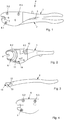
Figur 1 eine Draufsicht auf eine erfindungsgemässe Zange zum Schneiden von nicht näher gezeigten Werkstücken; -
Figur 2 eine teilweise dargestellte Draufsicht auf einen Zangenschenkel der Zange nachFigur 1 ; -
Figur 3 eine verkleinert dargestellte Draufsicht auf ein Druckelement der Zange nachFigur 1 ; -
Figur 4 eine Draufsicht auf eine Abdeckung für die Zange nachFigur 1 ; -
Figur 5 eine verkleinert dargestellte Draufsicht auf ein Schneidelement für die Zange nachFigur 1 ; -
Figur 6 eine um 90° gedrehte Draufsicht auf das Schneidelement gemässFigur 5 ; -
Figur 7 eine Seitenansicht eines Druckstücks aus der Zange nachFigur 1 ; -
Figur 8 eine Draufsicht auf das Druckstück gemässFigur 7 ; -
Figur 9 eine Draufsicht auf einen Feststeller für die erfindungsgemässe Zange nachFigur 1 ; -
Figur 10 eine Seitenansicht des Feststellers gemässFigur 9 ; -
Figur 11 eine Draufsicht auf die geöffnete Zange gemässFigur 1 mit der Anordnung der einzelnen Bauteile. - Eine erfindungsgemässe Zange P zum Schneiden von nicht näher gezeigten Werkstücken weist einen Zangenschenkel 1 und ein dem Zangenschenkel 1 zugeordnetes schenkelartiges Druckelement 2 auf. Der Zangenschenkel 1 stützt sich in Schliesslage über einen Anschlag 3 gegen das Druckelement 2 ab. Dabei kann der Anschlag 3 elastisch ausgebildet sein.
- Im vorderen Bereich des Zangenschenkels 1 ist eine Abdeckung 4 zu erkennen, welche die wesentlichen Funktionselemente der Zange P verbirgt. Die Abdeckung 4 ist dabei über drei Schraubenbolzen 5.1 bis 5.3 mit dem Zangenschenkel 1 verbunden. Die Schraubenbolzen 5.1 bis 5.3 greifen in die Gewindebohrungen 6.1 bis 6.3 des Zangenschenkels 1 ein, wie sie in
Figur 2 gezeigt sind. - Des Weiteren umrahmt die Abdeckung 4 mittels einer Ausnehmung 7 ein Zangenmaul 8, welches von dem Zangenschenkel 1 ausgebildet wird.
- In
Figur 2 ist ferner erkennbar, dass in dem Zangenschenkel 1 eine Führungsrinne 9 und ein Sackloch 10 vorgesehen sind. Des Weiteren sind Aufnahmen 11 und 12 ausgebildet. Die Aufnahme 11 dient der Lagerung eines später beschriebenen Anschlags, die Aufnahme 12 der Lagerung eines Drehzapfens 13 (sieheFigur 3 ), mit dem das Druckelement 2 in einer Drehmulde 14 in dem Zangenschenkel 1 sitzt. Neben diesem Drehzapfen 13 ist in dem Druckelement 2, gemässFigur 3 , eine Mulde 15 zur Aufnahme eines Rundstücks 22 eines später beschriebenen Druckstücks 21 ausgebildet. Zu dieser Mulde 15 hin ist ein weiteres Sackloch 16 offen. - In die oben erwähnte Führungsrinne 9 greift ein Führungszapfen 17 ein, der gemäss
Figur 5 und 6 von einem Schneidelement 18 abragt. Dieses Schneidelement 18 besitzt ein Schneidmaul 19, welches in seinen Konturen dem Zangenmaul 8 nachgeformt ist. Gegenüber dem Schneidmaul 19 ist an dem Schneidelement 18 eine Rastzahnung 20 vorgesehen. - Das oben erwähnte Druckstück 21, welches sich über ein Rundstück 22 in der Mulde 15 des Druckelementes 2 abstützt, ist in den
Figuren 7 und 8 gezeigt. Dieses Druckstück 21 besitzt eine Zahnleiste 23. In denFiguren 9 und 10 wird ein Feststeller 24 gezeigt. Dieser Feststeller 24 weist eine Rastleiste 25 auf und dieser gegenüberliegend einen Zughacken 26. Nahe der Rastleiste 25 ist ferner ein Anschlagnocken 27 vorgesehen. - Das Zusammenspiel der einzelnen Bauteile ist insbesondere in
Figur 11 erkennbar. Wesentlich ist dabei, dass das Schneidelement 18 im vorderen Bereich des Zangenschenkels 1 in einen Rollenkäfig 28 eingesetzt ist und in diesem Rollenkäfig 28 dreht. Diese Drehung erfolgt um einen Drehpunkt 29, wobei jeweils ein Grund des Zangenmauls 8 bzw. des Schneidmauls 19 sehr nahe an diesem Drehpunkt 29 angeordnet ist. - Im Übrigen ist erkennbar, dass das Schneidelement 18 mit seinem Führungszapfen 17 in die Führungsrinne 9 eingreift und in dieser Führungsrinne 9 in einem Radius um den Drehpunkt 29 geführt ist. Des Weiteren schlägt das Schneidelement 18 an einem in die Aufnahme 11 eingesetzten Anschlag 30 an.
- Das Druckelement 2 sitzt mit seinem Drehzapfen 13 in der Drehmulde 14 und kann in begrenztem Umfang gegenüber dem Zangenschenkel 1 bewegt werden. In der Mulde 15 ist das Druckstück 21 mittels des Rundstücks 22 gelagert und stützt sich über eine Schraubenfeder 31 in dem Sackloch 16 ab. Die Zahnleiste 23 des Druckstücks 21 wirkt dabei mit der Rastzahnung 20 des Schneidelements 18 zusammen.
- Der Festesteller 24 ist in einen Führungskanal 32 in dem Zangenschenkel 1 eingesetzt und in diesem Führungskanal 32 verschiebbar gelagert. Seine Rastleiste 25 überdeckt dabei zumindest teilweise die Zahnleiste 23 des Druckstücks 21. Der Anschlagnocken 27 bewirkt, dass der Feststeller 24 nicht unerwünscht nach hinten ausweichen kann.
- Des Weiteren ist in
Figur 11 ein Bolzen 33 angedeutet, der in das Sackloch 10 eingreift. Dieser Bolzen 33 kann federgelagert sein, sodass sich das Druckelement 2 gegenüber dem Zangenschenkel 1 federgelagert abstützt. - Die Funktionsweise der vorliegenden Erfindung ist folgende:
Zum Schneiden eines nicht näher gezeigten Werkstücks, wird dieses in das Zangen- bzw. Schneidmaul 8/19 eingeführt. Das Schneidelement 18 befindet sich dabei in der inFigur 11 gezeigten Ausgangsposition, sodass das Maul 8/19 weitestgehend geöffnet ist. Der Zangenschenkel 1 und das Druckelement 2 sind gespreizt, sodass die Zahnleiste 23 des Druckstücks 21 mit einer möglichst grossen Anzahl von Zähnen in Eingriff mit der Rastzahnung 20 des Schneidelements 18 steht. Dieser Eingriff wird durch Druck der Schraubenfeder 31 unterstützt. - Nun wird das Druckelement 2 zum Zangenschenkel 1 hin bewegt, wobei das Druckstück 21 das Schneidelement 18 mitnimmt, sodass dieses, geführt durch den Führungszapfen 17, in der Führungsrinne 9 und im Rollenkäfig 28 um den Drehpunkt 29 dreht. Dabei verringert sich die lichte Weite des Zangen- bzw. Schneidmauls 8/19, sodass das Schneidelement 18 in das Werkstück einschneidet. Gleichzeitig läuft auch die Rastzahnung 20 des Schneidelements 18 die Rastleiste 25 des Feststellers 24 ab und wird durch diesen Feststeller 24 gehalten, wenn nun zum Nachholen das Druckelement 2 wieder weg von dem Zangenschenkel 1 bewegt wird, sodass die Zahnleiste 23 des Druckstücks 21 entlang der Rastzahnung 20 fahren kann und in einen neuen Bereich dieser Rastzahnung 20 einfährt.
- Jetzt kann erneut das Druckelement 2 wieder gegen den Zangenschenkel 1 bewegt werden, wobei das Druckstück 21 über die Rastverbindung mit dem Schneidelement 18 dieses mitnimmt und um den Drehpunkt 29 dreht. Dies geschieht so lange, bis das Werkstück durchgeschnitten ist.
Bezugszeichenliste 1 Zangenschenkel 34 67 2 Druckelement 35 68 3 Anschlag 36 69 4 Abdeckung 37 70 5 Schraubenbolzen 38 71 6 Gewindebohrung 39 72 7 Ausnehmung 40 73 8 Zangenmaul 41 74 9 Führungsrinne 42 75 10 Sackloch 43 76 11 Aufnahme 44 77 12 Aufnahme 45 78 13 Drehzapfen 46 79 14 Drehmulde 47 15 Mulde 48 16 Sackloch 49 17 Führungszapfen 50 18 Schneidelement 51 19 Schneidmaul 52 20 Rastzahnung 53 21 Druckstück 54 22 Rundstück 55 23 Zahnleiste 56 24 Feststeller 57 25 Rastleiste 58 26 Zughaken 59 27 Anschlagnocken 60 P Zange 28 Rollenkäfig 61 29 Drehpunkt 62 30 Anschlag 63 31 Schraubenfeder 64 32 Führungskanal 65 33 Bolzen 66
Claims (6)
- Zange zum Schneiden von Werkstücken im medizinischen bzw. chirurgischen Bereich insbesondere aus Metall mit zumindest einem Zangenschenkel (1) und einem Druckelement (2), welche über einen Drehpunkt (13) miteinander verbunden sind, wobei der Zangenschenkel (1) ein Zangenmaul (8) zur Aufnahme des Werkstücks ausbildet und dem Zangenschenkel (1) ein Schneidelement (18) mit einem Schneidmaul (19) zugeordnet ist und das Schneidelement (18) mittels einer Rasteinrichtung (20, 23, 25) um einen Drehpunkt (29) drehbar gegenüber dem Zangenschenkel (1) angeordnet ist, wobei das Schneidelement (18) gegenüberliegend von dem Schneidmaul (19) eine Rastzahnung (20) aufweist und die Rastzahnung (20) mit einer Zahnleiste (23) eines Druckstücks (21) in Eingriff steht und das Druckstück (21) bzw. die Zahnleiste (23) mittels einem Kraftspeicher (31) in Eingriff mit der Rastzahnung (20) gehalten ist, wobei der Rastzahnung (20) ein Feststeller (24) mit einer weiteren Rastleiste (25) zugeordnet ist, dadurch gekennzeichnet, dass sich das Druckstück (21) mit einem Rundstück (22) in einer Mulde (15) in dem Druckelement (2) abstützt und der Feststeller (24) in dem Zangenschenkel (1) verschiebbar angeordnet ist.
- Zange nach Anspruch 1, dadurch gekennzeichnet, dass der Kraftspeicher (31) als Schraubenfeder in einem Sackloch (16) in dem Druckelement (2) gehalten ist.
- Zange nach Anspruch 1 oder 2, dadurch gekennzeichnet, dass ein Grund des Zangenmauls (8) und ein Grund des Schneidmauls (19) nahe einem Drehpunkt (29) angeordnet sind, um welchen das Schneidelement (18) in dem Zangenschenkel (1) dreht und ausserhalb des Zangenmauls (8) und des Schneidmauls (19) angeordnet ist.
- Zange nach wenigstens einem der Ansprüche 1 bis 3, dadurch gekennzeichnet, dass der Drehpunkt (13) als Drehzapfen (13) ausgebildet ist, das Druckelement (2) schenkelartig ausgebildet ist und mit dem Drehzapfen (13) in einer Drehmulde (14) in dem Zangenschenkel (1) sitzt.
- Zange nach wenigstens einem der Ansprüche 1 bis 4, dadurch gekennzeichnet, dass sich das Druckelement (2) über einen Kraftspeicher gegen den Zangenschenkel (1) abstützt.
- Zange nach Anspruch 5, dadurch gekennzeichnet, dass der Kraftspeicher ein federgelagerter Bolzen (33) ist.
Applications Claiming Priority (2)
| Application Number | Priority Date | Filing Date | Title |
|---|---|---|---|
| DE102011001013A DE102011001013A1 (de) | 2011-03-02 | 2011-03-02 | Zange zum Schneiden von Werkstücken |
| PCT/EP2012/053647 WO2012117096A1 (de) | 2011-03-02 | 2012-03-02 | Zange zum schneiden von werkstücken |
Publications (2)
| Publication Number | Publication Date |
|---|---|
| EP2680773A1 EP2680773A1 (de) | 2014-01-08 |
| EP2680773B1 true EP2680773B1 (de) | 2018-10-24 |
Family
ID=45922652
Family Applications (1)
| Application Number | Title | Priority Date | Filing Date |
|---|---|---|---|
| EP12711359.5A Not-in-force EP2680773B1 (de) | 2011-03-02 | 2012-03-02 | Zange zum schneiden von werkstücken |
Country Status (4)
| Country | Link |
|---|---|
| US (1) | US9457414B2 (de) |
| EP (1) | EP2680773B1 (de) |
| DE (1) | DE102011001013A1 (de) |
| WO (1) | WO2012117096A1 (de) |
Families Citing this family (6)
| Publication number | Priority date | Publication date | Assignee | Title |
|---|---|---|---|---|
| DE102011001013A1 (de) * | 2011-03-02 | 2012-09-06 | Alexander Merz | Zange zum Schneiden von Werkstücken |
| DE102013105751A1 (de) * | 2013-06-04 | 2014-12-04 | Karl Klappenecker GmbH & Co. KG | Zange |
| US20170340373A1 (en) * | 2015-04-30 | 2017-11-30 | Zhengzhou Zezheng Technical Services Ltd. | Kirschner wire bending device |
| TWI668084B (zh) * | 2018-12-28 | 2019-08-11 | 優品企業有限公司 | Steel cable cutter |
| US20230061887A1 (en) * | 2021-08-27 | 2023-03-02 | ln'Tech Medical SAS | Rod cutter |
| US12653593B2 (en) * | 2022-12-14 | 2026-06-16 | Sg, Llc | In situ rod cutters |
Family Cites Families (18)
| Publication number | Priority date | Publication date | Assignee | Title |
|---|---|---|---|---|
| US401308A (en) | 1889-04-09 | Nippers | ||
| AT17406B (de) | 1903-04-19 | 1904-08-25 | Johann Ockermueller | |
| US1820169A (en) * | 1929-12-09 | 1931-08-25 | Edward H Wigand | Pliers and the like |
| US2385835A (en) * | 1944-01-31 | 1945-10-02 | Elmer Brandell | Lever construction |
| US3210844A (en) * | 1962-10-08 | 1965-10-12 | Tontscheff Todor Kaniov | Cutting pliers |
| US3716879A (en) | 1971-06-21 | 1973-02-20 | Bayan Ltd | Manually actuatable tool |
| US4058893A (en) * | 1976-06-25 | 1977-11-22 | Boyajian Alfred | Bolt cutter |
| JPS5532061Y2 (de) * | 1977-01-25 | 1980-07-31 | ||
| US4312127A (en) * | 1979-08-23 | 1982-01-26 | Hanazono Kogu Kabushiki Kaisha | Cutting tool |
| DE3302875A1 (de) | 1983-01-28 | 1984-08-02 | Baudat E. Wolter KG, 7941 Dürmentingen | Schere zum querunterteilen von strangfoermigem schneidgut |
| DE3743605A1 (de) | 1987-12-22 | 1989-07-06 | Delma Elektro Med App | Chirurgische zange |
| EP0454605A3 (en) | 1990-04-25 | 1992-04-22 | International Business Machines Corporation | Bus request device in a direct memory access (dma) system |
| DE9004793U1 (de) | 1990-04-27 | 1991-01-03 | Josef Heiss Medizintechnik GmbH, 7200 Tuttlingen | Zange zum Schneiden chirurgischer Nägel, Drähte od.dgl. |
| DE4329220A1 (de) | 1993-08-31 | 1995-03-09 | Volkmar Dipl Ing Dr Me Jansson | Medizinische Drahtzange |
| US20080000091A1 (en) | 2006-06-29 | 2008-01-03 | Toho Koki Co., Ltd. | Threaded Rod Cutter |
| US7886446B2 (en) * | 2008-03-07 | 2011-02-15 | Hsiu-Man Yu Chen | Pipe cutting pincers |
| AU2010101247B4 (en) * | 2010-11-12 | 2013-11-21 | 2Wp International Pty Ltd | Dual mode ratchet pruners |
| DE102011001013A1 (de) * | 2011-03-02 | 2012-09-06 | Alexander Merz | Zange zum Schneiden von Werkstücken |
-
2011
- 2011-03-02 DE DE102011001013A patent/DE102011001013A1/de not_active Withdrawn
-
2012
- 2012-03-02 EP EP12711359.5A patent/EP2680773B1/de not_active Not-in-force
- 2012-03-02 WO PCT/EP2012/053647 patent/WO2012117096A1/de not_active Ceased
- 2012-03-02 US US14/002,214 patent/US9457414B2/en not_active Expired - Fee Related
Non-Patent Citations (1)
| Title |
|---|
| None * |
Also Published As
| Publication number | Publication date |
|---|---|
| DE102011001013A1 (de) | 2012-09-06 |
| US20140053411A1 (en) | 2014-02-27 |
| WO2012117096A1 (de) | 2012-09-07 |
| EP2680773A1 (de) | 2014-01-08 |
| US9457414B2 (en) | 2016-10-04 |
Similar Documents
| Publication | Publication Date | Title |
|---|---|---|
| EP1996091B1 (de) | Chirurgisches instrument | |
| EP2996585B1 (de) | Chirurgisches instrument | |
| EP2594210B1 (de) | Medizinisches Instrument | |
| DE3709067A1 (de) | Medizinisches, insbesondere chirurgisches instrument | |
| EP2680773A1 (de) | Zange zum schneiden von werkstücken | |
| EP2452644A2 (de) | Repositionszange mit einer Bohrhilfe | |
| EP3261566B1 (de) | Knochenplatte und operationsset zum fixieren von knochenfragmenten | |
| DE102009006689A1 (de) | Chirurgisches Instrument | |
| EP1632151B1 (de) | Schubladenzarge | |
| EP2691030A1 (de) | Chirurgischer clip-applikator | |
| DE102014101009A1 (de) | Knochenspreizer mit verdrehbaren Valven | |
| DE202017104585U1 (de) | Mit einer einzigen Schneidplatte bzw. mit Doppelklingen ausgeführte stark scherkräftige Drahtseilschere | |
| EP2730239B1 (de) | Chirurgisches fräswerkzeug | |
| DE102009007455B4 (de) | Chirurgisches Trenninstrument | |
| DE102011076577B3 (de) | Schneidsatzaufnahme | |
| DE10320477B3 (de) | Chirurgisches Instrument | |
| DE202015008921U1 (de) | Chirurgisches Instrument | |
| EP1491155A1 (de) | Schiebeschaftinstrument für chirurgische Zwecke, insbesondere Knochen- und Gewebestanze | |
| EP3003176B1 (de) | Zange | |
| DE102015114306A1 (de) | Vorrichtung zum Abtrennen und Entfernen von Gewebeteilen | |
| DE102006036117B4 (de) | Chirurgisches Instrument zum Spreizen von zwei zueinander benachbarten Operationsöffnungen | |
| EP2941207B1 (de) | Chirurgisches schiebeschaftinstrument | |
| DE202011000754U1 (de) | Chirurgischer Clip-Applikator | |
| DE7817887U1 (de) | ||
| DE10323958B4 (de) | Chirurgisches Instrument |
Legal Events
| Date | Code | Title | Description |
|---|---|---|---|
| PUAI | Public reference made under article 153(3) epc to a published international application that has entered the european phase |
Free format text: ORIGINAL CODE: 0009012 |
|
| 17P | Request for examination filed |
Effective date: 20131001 |
|
| AK | Designated contracting states |
Kind code of ref document: A1 Designated state(s): AL AT BE BG CH CY CZ DE DK EE ES FI FR GB GR HR HU IE IS IT LI LT LU LV MC MK MT NL NO PL PT RO RS SE SI SK SM TR |
|
| DAX | Request for extension of the european patent (deleted) | ||
| GRAP | Despatch of communication of intention to grant a patent |
Free format text: ORIGINAL CODE: EPIDOSNIGR1 |
|
| STAA | Information on the status of an ep patent application or granted ep patent |
Free format text: STATUS: GRANT OF PATENT IS INTENDED |
|
| RIC1 | Information provided on ipc code assigned before grant |
Ipc: B25B 7/12 20060101ALI20171020BHEP Ipc: A61B 17/88 20060101AFI20171020BHEP Ipc: B23D 29/02 20060101ALI20171020BHEP Ipc: B26B 17/02 20060101ALI20171020BHEP |
|
| INTG | Intention to grant announced |
Effective date: 20171127 |
|
| GRAS | Grant fee paid |
Free format text: ORIGINAL CODE: EPIDOSNIGR3 |
|
| GRAA | (expected) grant |
Free format text: ORIGINAL CODE: 0009210 |
|
| STAA | Information on the status of an ep patent application or granted ep patent |
Free format text: STATUS: THE PATENT HAS BEEN GRANTED |
|
| AK | Designated contracting states |
Kind code of ref document: B1 Designated state(s): AL AT BE BG CH CY CZ DE DK EE ES FI FR GB GR HR HU IE IS IT LI LT LU LV MC MK MT NL NO PL PT RO RS SE SI SK SM TR |
|
| REG | Reference to a national code |
Ref country code: GB Ref legal event code: FG4D Free format text: NOT ENGLISH |
|
| REG | Reference to a national code |
Ref country code: CH Ref legal event code: EP |
|
| REG | Reference to a national code |
Ref country code: IE Ref legal event code: FG4D Free format text: LANGUAGE OF EP DOCUMENT: GERMAN |
|
| REG | Reference to a national code |
Ref country code: AT Ref legal event code: REF Ref document number: 1055757 Country of ref document: AT Kind code of ref document: T Effective date: 20181115 |
|
| REG | Reference to a national code |
Ref country code: DE Ref legal event code: R096 Ref document number: 502012013676 Country of ref document: DE |
|
| REG | Reference to a national code |
Ref country code: NL Ref legal event code: MP Effective date: 20181024 |
|
| REG | Reference to a national code |
Ref country code: LT Ref legal event code: MG4D |
|
| PG25 | Lapsed in a contracting state [announced via postgrant information from national office to epo] |
Ref country code: NL Free format text: LAPSE BECAUSE OF FAILURE TO SUBMIT A TRANSLATION OF THE DESCRIPTION OR TO PAY THE FEE WITHIN THE PRESCRIBED TIME-LIMIT Effective date: 20181024 |
|
| PG25 | Lapsed in a contracting state [announced via postgrant information from national office to epo] |
Ref country code: HR Free format text: LAPSE BECAUSE OF FAILURE TO SUBMIT A TRANSLATION OF THE DESCRIPTION OR TO PAY THE FEE WITHIN THE PRESCRIBED TIME-LIMIT Effective date: 20181024 Ref country code: PL Free format text: LAPSE BECAUSE OF FAILURE TO SUBMIT A TRANSLATION OF THE DESCRIPTION OR TO PAY THE FEE WITHIN THE PRESCRIBED TIME-LIMIT Effective date: 20181024 Ref country code: LT Free format text: LAPSE BECAUSE OF FAILURE TO SUBMIT A TRANSLATION OF THE DESCRIPTION OR TO PAY THE FEE WITHIN THE PRESCRIBED TIME-LIMIT Effective date: 20181024 Ref country code: NO Free format text: LAPSE BECAUSE OF FAILURE TO SUBMIT A TRANSLATION OF THE DESCRIPTION OR TO PAY THE FEE WITHIN THE PRESCRIBED TIME-LIMIT Effective date: 20190124 Ref country code: LV Free format text: LAPSE BECAUSE OF FAILURE TO SUBMIT A TRANSLATION OF THE DESCRIPTION OR TO PAY THE FEE WITHIN THE PRESCRIBED TIME-LIMIT Effective date: 20181024 Ref country code: IS Free format text: LAPSE BECAUSE OF FAILURE TO SUBMIT A TRANSLATION OF THE DESCRIPTION OR TO PAY THE FEE WITHIN THE PRESCRIBED TIME-LIMIT Effective date: 20190224 Ref country code: ES Free format text: LAPSE BECAUSE OF FAILURE TO SUBMIT A TRANSLATION OF THE DESCRIPTION OR TO PAY THE FEE WITHIN THE PRESCRIBED TIME-LIMIT Effective date: 20181024 Ref country code: BG Free format text: LAPSE BECAUSE OF FAILURE TO SUBMIT A TRANSLATION OF THE DESCRIPTION OR TO PAY THE FEE WITHIN THE PRESCRIBED TIME-LIMIT Effective date: 20190124 Ref country code: FI Free format text: LAPSE BECAUSE OF FAILURE TO SUBMIT A TRANSLATION OF THE DESCRIPTION OR TO PAY THE FEE WITHIN THE PRESCRIBED TIME-LIMIT Effective date: 20181024 |
|
| PG25 | Lapsed in a contracting state [announced via postgrant information from national office to epo] |
Ref country code: GR Free format text: LAPSE BECAUSE OF FAILURE TO SUBMIT A TRANSLATION OF THE DESCRIPTION OR TO PAY THE FEE WITHIN THE PRESCRIBED TIME-LIMIT Effective date: 20190125 Ref country code: RS Free format text: LAPSE BECAUSE OF FAILURE TO SUBMIT A TRANSLATION OF THE DESCRIPTION OR TO PAY THE FEE WITHIN THE PRESCRIBED TIME-LIMIT Effective date: 20181024 Ref country code: AL Free format text: LAPSE BECAUSE OF FAILURE TO SUBMIT A TRANSLATION OF THE DESCRIPTION OR TO PAY THE FEE WITHIN THE PRESCRIBED TIME-LIMIT Effective date: 20181024 Ref country code: SE Free format text: LAPSE BECAUSE OF FAILURE TO SUBMIT A TRANSLATION OF THE DESCRIPTION OR TO PAY THE FEE WITHIN THE PRESCRIBED TIME-LIMIT Effective date: 20181024 Ref country code: PT Free format text: LAPSE BECAUSE OF FAILURE TO SUBMIT A TRANSLATION OF THE DESCRIPTION OR TO PAY THE FEE WITHIN THE PRESCRIBED TIME-LIMIT Effective date: 20190224 |
|
| REG | Reference to a national code |
Ref country code: DE Ref legal event code: R097 Ref document number: 502012013676 Country of ref document: DE |
|
| PG25 | Lapsed in a contracting state [announced via postgrant information from national office to epo] |
Ref country code: IT Free format text: LAPSE BECAUSE OF FAILURE TO SUBMIT A TRANSLATION OF THE DESCRIPTION OR TO PAY THE FEE WITHIN THE PRESCRIBED TIME-LIMIT Effective date: 20181024 Ref country code: DK Free format text: LAPSE BECAUSE OF FAILURE TO SUBMIT A TRANSLATION OF THE DESCRIPTION OR TO PAY THE FEE WITHIN THE PRESCRIBED TIME-LIMIT Effective date: 20181024 Ref country code: CZ Free format text: LAPSE BECAUSE OF FAILURE TO SUBMIT A TRANSLATION OF THE DESCRIPTION OR TO PAY THE FEE WITHIN THE PRESCRIBED TIME-LIMIT Effective date: 20181024 |
|
| PG25 | Lapsed in a contracting state [announced via postgrant information from national office to epo] |
Ref country code: RO Free format text: LAPSE BECAUSE OF FAILURE TO SUBMIT A TRANSLATION OF THE DESCRIPTION OR TO PAY THE FEE WITHIN THE PRESCRIBED TIME-LIMIT Effective date: 20181024 Ref country code: SM Free format text: LAPSE BECAUSE OF FAILURE TO SUBMIT A TRANSLATION OF THE DESCRIPTION OR TO PAY THE FEE WITHIN THE PRESCRIBED TIME-LIMIT Effective date: 20181024 Ref country code: EE Free format text: LAPSE BECAUSE OF FAILURE TO SUBMIT A TRANSLATION OF THE DESCRIPTION OR TO PAY THE FEE WITHIN THE PRESCRIBED TIME-LIMIT Effective date: 20181024 Ref country code: SK Free format text: LAPSE BECAUSE OF FAILURE TO SUBMIT A TRANSLATION OF THE DESCRIPTION OR TO PAY THE FEE WITHIN THE PRESCRIBED TIME-LIMIT Effective date: 20181024 |
|
| PLBE | No opposition filed within time limit |
Free format text: ORIGINAL CODE: 0009261 |
|
| STAA | Information on the status of an ep patent application or granted ep patent |
Free format text: STATUS: NO OPPOSITION FILED WITHIN TIME LIMIT |
|
| REG | Reference to a national code |
Ref country code: DE Ref legal event code: R119 Ref document number: 502012013676 Country of ref document: DE |
|
| 26N | No opposition filed |
Effective date: 20190725 |
|
| PG25 | Lapsed in a contracting state [announced via postgrant information from national office to epo] |
Ref country code: SI Free format text: LAPSE BECAUSE OF FAILURE TO SUBMIT A TRANSLATION OF THE DESCRIPTION OR TO PAY THE FEE WITHIN THE PRESCRIBED TIME-LIMIT Effective date: 20181024 Ref country code: MC Free format text: LAPSE BECAUSE OF FAILURE TO SUBMIT A TRANSLATION OF THE DESCRIPTION OR TO PAY THE FEE WITHIN THE PRESCRIBED TIME-LIMIT Effective date: 20181024 |
|
| REG | Reference to a national code |
Ref country code: CH Ref legal event code: PL |
|
| GBPC | Gb: european patent ceased through non-payment of renewal fee |
Effective date: 20190302 |
|
| PG25 | Lapsed in a contracting state [announced via postgrant information from national office to epo] |
Ref country code: LU Free format text: LAPSE BECAUSE OF NON-PAYMENT OF DUE FEES Effective date: 20190302 |
|
| REG | Reference to a national code |
Ref country code: BE Ref legal event code: MM Effective date: 20190331 |
|
| PG25 | Lapsed in a contracting state [announced via postgrant information from national office to epo] |
Ref country code: GB Free format text: LAPSE BECAUSE OF NON-PAYMENT OF DUE FEES Effective date: 20190302 Ref country code: IE Free format text: LAPSE BECAUSE OF NON-PAYMENT OF DUE FEES Effective date: 20190302 Ref country code: CH Free format text: LAPSE BECAUSE OF NON-PAYMENT OF DUE FEES Effective date: 20190331 Ref country code: DE Free format text: LAPSE BECAUSE OF NON-PAYMENT OF DUE FEES Effective date: 20191001 Ref country code: LI Free format text: LAPSE BECAUSE OF NON-PAYMENT OF DUE FEES Effective date: 20190331 |
|
| PG25 | Lapsed in a contracting state [announced via postgrant information from national office to epo] |
Ref country code: FR Free format text: LAPSE BECAUSE OF NON-PAYMENT OF DUE FEES Effective date: 20190331 Ref country code: BE Free format text: LAPSE BECAUSE OF NON-PAYMENT OF DUE FEES Effective date: 20190331 |
|
| PG25 | Lapsed in a contracting state [announced via postgrant information from national office to epo] |
Ref country code: TR Free format text: LAPSE BECAUSE OF FAILURE TO SUBMIT A TRANSLATION OF THE DESCRIPTION OR TO PAY THE FEE WITHIN THE PRESCRIBED TIME-LIMIT Effective date: 20181024 |
|
| PG25 | Lapsed in a contracting state [announced via postgrant information from national office to epo] |
Ref country code: MT Free format text: LAPSE BECAUSE OF FAILURE TO SUBMIT A TRANSLATION OF THE DESCRIPTION OR TO PAY THE FEE WITHIN THE PRESCRIBED TIME-LIMIT Effective date: 20181024 |
|
| REG | Reference to a national code |
Ref country code: AT Ref legal event code: MM01 Ref document number: 1055757 Country of ref document: AT Kind code of ref document: T Effective date: 20190302 |
|
| PG25 | Lapsed in a contracting state [announced via postgrant information from national office to epo] |
Ref country code: AT Free format text: LAPSE BECAUSE OF NON-PAYMENT OF DUE FEES Effective date: 20190302 |
|
| PG25 | Lapsed in a contracting state [announced via postgrant information from national office to epo] |
Ref country code: CY Free format text: LAPSE BECAUSE OF FAILURE TO SUBMIT A TRANSLATION OF THE DESCRIPTION OR TO PAY THE FEE WITHIN THE PRESCRIBED TIME-LIMIT Effective date: 20181024 |
|
| PG25 | Lapsed in a contracting state [announced via postgrant information from national office to epo] |
Ref country code: HU Free format text: LAPSE BECAUSE OF FAILURE TO SUBMIT A TRANSLATION OF THE DESCRIPTION OR TO PAY THE FEE WITHIN THE PRESCRIBED TIME-LIMIT; INVALID AB INITIO Effective date: 20120302 |
|
| PG25 | Lapsed in a contracting state [announced via postgrant information from national office to epo] |
Ref country code: MK Free format text: LAPSE BECAUSE OF FAILURE TO SUBMIT A TRANSLATION OF THE DESCRIPTION OR TO PAY THE FEE WITHIN THE PRESCRIBED TIME-LIMIT Effective date: 20181024 |