EP2674585B1 - Leichtbau-Schalldämpfer - Google Patents
Leichtbau-Schalldämpfer Download PDFInfo
- Publication number
- EP2674585B1 EP2674585B1 EP13170271.4A EP13170271A EP2674585B1 EP 2674585 B1 EP2674585 B1 EP 2674585B1 EP 13170271 A EP13170271 A EP 13170271A EP 2674585 B1 EP2674585 B1 EP 2674585B1
- Authority
- EP
- European Patent Office
- Prior art keywords
- silencer
- housing
- sandwich plate
- muffler
- exhaust gas
- Prior art date
- Legal status (The legal status is an assumption and is not a legal conclusion. Google has not performed a legal analysis and makes no representation as to the accuracy of the status listed.)
- Active
Links
- 230000003584 silencer Effects 0.000 claims description 30
- 238000002485 combustion reaction Methods 0.000 claims description 22
- 239000002184 metal Substances 0.000 claims description 18
- 238000007599 discharging Methods 0.000 claims description 3
- 230000000295 complement effect Effects 0.000 claims description 2
- 238000004519 manufacturing process Methods 0.000 description 5
- 238000005452 bending Methods 0.000 description 4
- 238000004026 adhesive bonding Methods 0.000 description 3
- 238000010276 construction Methods 0.000 description 3
- 238000005476 soldering Methods 0.000 description 3
- 230000005540 biological transmission Effects 0.000 description 2
- 230000001419 dependent effect Effects 0.000 description 2
- 238000003466 welding Methods 0.000 description 2
- 239000006096 absorbing agent Substances 0.000 description 1
- 230000005284 excitation Effects 0.000 description 1
- 239000000446 fuel Substances 0.000 description 1
- 230000000977 initiatory effect Effects 0.000 description 1
- 238000009434 installation Methods 0.000 description 1
- 238000005192 partition Methods 0.000 description 1
Images


Classifications
-
- F—MECHANICAL ENGINEERING; LIGHTING; HEATING; WEAPONS; BLASTING
- F01—MACHINES OR ENGINES IN GENERAL; ENGINE PLANTS IN GENERAL; STEAM ENGINES
- F01N—GAS-FLOW SILENCERS OR EXHAUST APPARATUS FOR MACHINES OR ENGINES IN GENERAL; GAS-FLOW SILENCERS OR EXHAUST APPARATUS FOR INTERNAL COMBUSTION ENGINES
- F01N13/00—Exhaust or silencing apparatus characterised by constructional features ; Exhaust or silencing apparatus, or parts thereof, having pertinent characteristics not provided for in, or of interest apart from, groups F01N1/00 - F01N5/00, F01N9/00, F01N11/00
- F01N13/007—Apparatus used as intake or exhaust silencer
-
- F—MECHANICAL ENGINEERING; LIGHTING; HEATING; WEAPONS; BLASTING
- F01—MACHINES OR ENGINES IN GENERAL; ENGINE PLANTS IN GENERAL; STEAM ENGINES
- F01N—GAS-FLOW SILENCERS OR EXHAUST APPARATUS FOR MACHINES OR ENGINES IN GENERAL; GAS-FLOW SILENCERS OR EXHAUST APPARATUS FOR INTERNAL COMBUSTION ENGINES
- F01N13/00—Exhaust or silencing apparatus characterised by constructional features ; Exhaust or silencing apparatus, or parts thereof, having pertinent characteristics not provided for in, or of interest apart from, groups F01N1/00 - F01N5/00, F01N9/00, F01N11/00
- F01N13/14—Exhaust or silencing apparatus characterised by constructional features ; Exhaust or silencing apparatus, or parts thereof, having pertinent characteristics not provided for in, or of interest apart from, groups F01N1/00 - F01N5/00, F01N9/00, F01N11/00 having thermal insulation
- F01N13/141—Double-walled exhaust pipes or housings
-
- F—MECHANICAL ENGINEERING; LIGHTING; HEATING; WEAPONS; BLASTING
- F01—MACHINES OR ENGINES IN GENERAL; ENGINE PLANTS IN GENERAL; STEAM ENGINES
- F01N—GAS-FLOW SILENCERS OR EXHAUST APPARATUS FOR MACHINES OR ENGINES IN GENERAL; GAS-FLOW SILENCERS OR EXHAUST APPARATUS FOR INTERNAL COMBUSTION ENGINES
- F01N1/00—Silencing apparatus characterised by method of silencing
- F01N1/08—Silencing apparatus characterised by method of silencing by reducing exhaust energy by throttling or whirling
- F01N1/084—Silencing apparatus characterised by method of silencing by reducing exhaust energy by throttling or whirling the gases flowing through the silencer two or more times longitudinally in opposite directions, e.g. using parallel or concentric tubes
-
- F—MECHANICAL ENGINEERING; LIGHTING; HEATING; WEAPONS; BLASTING
- F01—MACHINES OR ENGINES IN GENERAL; ENGINE PLANTS IN GENERAL; STEAM ENGINES
- F01N—GAS-FLOW SILENCERS OR EXHAUST APPARATUS FOR MACHINES OR ENGINES IN GENERAL; GAS-FLOW SILENCERS OR EXHAUST APPARATUS FOR INTERNAL COMBUSTION ENGINES
- F01N13/00—Exhaust or silencing apparatus characterised by constructional features ; Exhaust or silencing apparatus, or parts thereof, having pertinent characteristics not provided for in, or of interest apart from, groups F01N1/00 - F01N5/00, F01N9/00, F01N11/00
- F01N13/14—Exhaust or silencing apparatus characterised by constructional features ; Exhaust or silencing apparatus, or parts thereof, having pertinent characteristics not provided for in, or of interest apart from, groups F01N1/00 - F01N5/00, F01N9/00, F01N11/00 having thermal insulation
- F01N13/148—Multiple layers of insulating material
-
- F—MECHANICAL ENGINEERING; LIGHTING; HEATING; WEAPONS; BLASTING
- F01—MACHINES OR ENGINES IN GENERAL; ENGINE PLANTS IN GENERAL; STEAM ENGINES
- F01N—GAS-FLOW SILENCERS OR EXHAUST APPARATUS FOR MACHINES OR ENGINES IN GENERAL; GAS-FLOW SILENCERS OR EXHAUST APPARATUS FOR INTERNAL COMBUSTION ENGINES
- F01N13/00—Exhaust or silencing apparatus characterised by constructional features ; Exhaust or silencing apparatus, or parts thereof, having pertinent characteristics not provided for in, or of interest apart from, groups F01N1/00 - F01N5/00, F01N9/00, F01N11/00
- F01N13/18—Construction facilitating manufacture, assembly, or disassembly
- F01N13/1872—Construction facilitating manufacture, assembly, or disassembly the assembly using stamp-formed parts or otherwise deformed sheet-metal
-
- F—MECHANICAL ENGINEERING; LIGHTING; HEATING; WEAPONS; BLASTING
- F01—MACHINES OR ENGINES IN GENERAL; ENGINE PLANTS IN GENERAL; STEAM ENGINES
- F01N—GAS-FLOW SILENCERS OR EXHAUST APPARATUS FOR MACHINES OR ENGINES IN GENERAL; GAS-FLOW SILENCERS OR EXHAUST APPARATUS FOR INTERNAL COMBUSTION ENGINES
- F01N13/00—Exhaust or silencing apparatus characterised by constructional features ; Exhaust or silencing apparatus, or parts thereof, having pertinent characteristics not provided for in, or of interest apart from, groups F01N1/00 - F01N5/00, F01N9/00, F01N11/00
- F01N13/18—Construction facilitating manufacture, assembly, or disassembly
- F01N13/1888—Construction facilitating manufacture, assembly, or disassembly the housing of the assembly consisting of two or more parts, e.g. two half-shells
- F01N13/1894—Construction facilitating manufacture, assembly, or disassembly the housing of the assembly consisting of two or more parts, e.g. two half-shells the parts being assembled in longitudinal direction
-
- F—MECHANICAL ENGINEERING; LIGHTING; HEATING; WEAPONS; BLASTING
- F01—MACHINES OR ENGINES IN GENERAL; ENGINE PLANTS IN GENERAL; STEAM ENGINES
- F01N—GAS-FLOW SILENCERS OR EXHAUST APPARATUS FOR MACHINES OR ENGINES IN GENERAL; GAS-FLOW SILENCERS OR EXHAUST APPARATUS FOR INTERNAL COMBUSTION ENGINES
- F01N2450/00—Methods or apparatus for fitting, inserting or repairing different elements
- F01N2450/24—Methods or apparatus for fitting, inserting or repairing different elements by bolts, screws, rivets or the like
-
- F—MECHANICAL ENGINEERING; LIGHTING; HEATING; WEAPONS; BLASTING
- F01—MACHINES OR ENGINES IN GENERAL; ENGINE PLANTS IN GENERAL; STEAM ENGINES
- F01N—GAS-FLOW SILENCERS OR EXHAUST APPARATUS FOR MACHINES OR ENGINES IN GENERAL; GAS-FLOW SILENCERS OR EXHAUST APPARATUS FOR INTERNAL COMBUSTION ENGINES
- F01N2490/00—Structure, disposition or shape of gas-chambers
- F01N2490/08—Two or more expansion chambers in series separated by apertured walls only
-
- F—MECHANICAL ENGINEERING; LIGHTING; HEATING; WEAPONS; BLASTING
- F01—MACHINES OR ENGINES IN GENERAL; ENGINE PLANTS IN GENERAL; STEAM ENGINES
- F01N—GAS-FLOW SILENCERS OR EXHAUST APPARATUS FOR MACHINES OR ENGINES IN GENERAL; GAS-FLOW SILENCERS OR EXHAUST APPARATUS FOR INTERNAL COMBUSTION ENGINES
- F01N2490/00—Structure, disposition or shape of gas-chambers
- F01N2490/15—Plurality of resonance or dead chambers
- F01N2490/155—Plurality of resonance or dead chambers being disposed one after the other in flow direction
-
- F—MECHANICAL ENGINEERING; LIGHTING; HEATING; WEAPONS; BLASTING
- F01—MACHINES OR ENGINES IN GENERAL; ENGINE PLANTS IN GENERAL; STEAM ENGINES
- F01N—GAS-FLOW SILENCERS OR EXHAUST APPARATUS FOR MACHINES OR ENGINES IN GENERAL; GAS-FLOW SILENCERS OR EXHAUST APPARATUS FOR INTERNAL COMBUSTION ENGINES
- F01N2530/00—Selection of materials for tubes, chambers or housings
- F01N2530/26—Multi-layered walls
Definitions
- the present invention relates to a silencer for an exhaust system of an internal combustion engine, in particular of a motor vehicle.
- the invention further relates to an exhaust system with such a silencer and an internal combustion engine with such an exhaust system.
- Silencers typically include a housing that encloses a muffler volume, and at least one inlet tube and at least one outlet tube.
- the muffler can then be fluidly connected to the rest of the exhaust system via the inlet pipe and the outlet pipe.
- the muffler may also comprise at least one holding element with which the muffler can be attached to a support structure, for example the internal combustion engine of a motor vehicle.
- a support structure for example the internal combustion engine of a motor vehicle.
- the GB 2 352 480 A a silencer with a sandwich plate.
- the WO 2012/055949 A1 discloses a silencer having a housing with a sandwich plate forming part of a housing shell.
- the present invention addresses the problem of providing a muffler of the type mentioned an improved embodiment, which is particularly suitable for the realization of a lightweight construction. This problem is solved according to the invention by the subject matter of the independent claims. Advantageous embodiments are the subject of the dependent claims.
- the muffler according to the invention has a sandwich plate, wherein this sandwich plate forms a part of a housing shell of the housing of the muffler.
- the muffler further comprises a self-supporting support structure, which in turn comprises a tube assembly which is at least partially disposed in the housing interior.
- This pipe arrangement may comprise, for example, an exhaust gas supply line and an exhaust gas discharge line, by means of which exhaust gas from an exhaust system of an internal combustion engine including the sound to be damped supplied to the muffler and can be discharged therefrom again.
- the tube assembly can be supported mechanically stable in the housing of the muffler.
- the sandwich panel according to the invention can be used, which is flat for optimum attachment of the muffler to the subfloor and yet has a very high mechanical stability.
- the silencer according to the invention can also be mounted in the space in a motor vehicle usually spatially very limited space and, if necessary, this form correspondingly flat.
- each such sheet metal panel layer may have a thickness of about 0.1 mm, the total weight of such a sandwich panel compared to conventional sheet metal walls with a thickness of sheet metal wall 1.5 mm significantly reduced and thus particularly suitable for stiffening large areas.
- sandwich panels in silencers (instead of conventional sheet metal walls) can thus achieve a significant weight savings.
- the muffler according to the invention can consequently be manufactured in lightweight construction, it being ensured at the same time that the mechanical or mechanical bending moments required for the reception and transmission of the muffler are present.
- the self-supporting support structure comprises at least one intermediate floor.
- Such an intermediate floor can be used to support the pipe arrangement on the self-supporting support structure and thus further improve the mechanical stability of the muffler.
- the sandwich panel is part of the self-supporting support structure. This allows a particularly good transmission of forces or torques supplied to the muffler via the self-supporting support structure, for example to a discharge line of the pipe arrangement.
- the muffler comprises a jacket hood, which completes the sandwich panel to the housing shell of the housing of the muffler according to the invention.
- the muffler has a first and a second end floor, which complete the housing shell to the housing.
- the first or second end floor can each be adhesively bonded, soldered or welded to the housing jacket, so that the housing jacket with the two end floors forms a gas-tight housing. Since the two end floors have no supporting function, these may also be preferably formed as a thin sheet metal walls.
- the jacket cover can be integrally connected to the first and / or to the second end floor. This means that the jacket hood as well as the first and second end floor form a single workpiece, which in the manner of a hood connected to the sandwich panel and in particular this welded can be.
- the jacket hood integrally connected to the first and second end floor can be designed in the manner of a shell.
- the shell hood in a longitudinal section of the muffler have two edge portions for attachment to the at least one sandwich panel, which, to the outside, away from the housing interior of the muffler , or inwards, towards the housing interior, stand out.
- the first or / and second end floor of the silencer can each have a first or second through-opening.
- the crude arrangement may comprise at least one supply and discharge pipe with a supply or discharge opening, which are performed through the first and second through-openings from the outside into the housing interior, such that the supply or discharge opening in the at least a chamber of the muffler is arranged.
- the at least one intermediate bottom can have a first and a second end section, the first end section then being attached to the first sandwich panel and the second end portion can be supported on the further sandwich panel or on the jacket hood.
- At least one through-opening may be provided in the intermediate bottom in an area arranged between the two end sections, through which the at least one supply or discharge pipe can be made. In this way, the supply and discharge pipe can be mechanically supported particularly stable in the muffler.
- the at least one intermediate floor may be an additional sandwich panel (in addition to the first and second sandwich panels).
- a particularly high mechanical stability can be achieved in the silencer according to the invention by means of the additional sandwich plate.
- the at least one intermediate floor may also be a sheet metal wall. This variant is particularly preferable when the mechanical stability does not have to be substantially increased by means of the intermediate bottom, so that the sheet metal wall can serve, for example, as a pure partition for separating the chamber in the housing interior into a first and second sub-chamber, by means of which in Sound absorber introduced sound can be particularly well damped.
- the sandwich panel can be connected to the other sandwich panel or the jacket hood by means of welding, gluing or soldering.
- the at least one sandwich panel in a longitudinal section profile of the muffler may have a first and second end section with respect to the longitudinal direction, in which a wall thickness of the sandwich panel has a lower value than in one arranged between the two end sections Area of the sandwich panel.
- the sandwich panel can then be riveted to the two end portions with complementary to these two end portions edge portions of the jacket cover.
- the invention further relates to an exhaust system, in particular for an internal combustion engine of a motor vehicle, with an exhaust gas removal pipe for discharging exhaust gas from the exhaust system and with a silencer with one or more of the aforementioned features.
- the tube assembly of the muffler may have a fluidically connected to the exhaust gas discharge pipe feed pipe.
- the present invention further relates to an internal combustion engine having a combustion chamber and an exhaust system with one or more of the aforementioned features, wherein the combustion chamber of the internal combustion engine can be fluidly connected to the exhaust system by means of a connecting pipe.
- FIG. 1 shows the muffler 1 while in a longitudinal sectional view, the FIG. 2 in a side view.
- the silencer 1 comprises a housing 2, which has a housing jacket 3 extending in a circumferential direction U of the housing.
- the silencer 1 further comprises a housing interior 4 having at least one chamber 8, which is enclosed by the housing 2, as well as a self-supporting support structure 5 and a sandwich plate 6.
- the sandwich panel 6 forms a part of the housing shell 3.
- the self-supporting support structure 5 comprises a tube arrangement 7, which is arranged partially in the housing interior 4.
- the muffler 1 further comprises a jacket hood 9, which completes the first sandwich panel 6 to the housing shell 3 (see. FIG. 2 ).
- the sandwich panel 6 may be connected to the jacket hood 9 by means of welding, gluing or soldering.
- the jacket hood 9 due to their shell-like design completes the sandwich panel 6 not only to the housing shell 3, but to the entire housing 2. This means in particular that for the completion of the housing shell 3 no additional end floors are required, which greatly simplifies the construction and thus the production of the silencer 1 according to the invention.
- the shroud 9 may also be considered integral with first and second end bottoms.
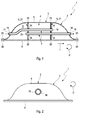
- the muffler 1 ' in one in the FIG. 3 shown, not belonging to the invention variant of the embodiment of FIG. 1 the muffler 1 'as an alternative to the jacket hood 9, a further sandwich panel 10', which is part of the self-supporting support structure, and a first and a second metal wall 11 ', 12' include. These then complete together the first sandwich panel 6 'to the housing shell 3'.
- the FIG. 4 shows the muffler 1 'of FIG. 3 according to the section line IV
- the FIG. 5 shows the muffler 1 'according to the section line V.
- the sandwich panel 6 'and the further sandwich panel 10' as well as the first and second panel wall 11 ', 12' may be arranged in the cross-sectional profile of the muffler 1 ', preferably substantially opposite one another. In principle, however, other arrangement geometries are also conceivable in further variants.
- the first and second sheet metal walls 11 ', 12' simultaneously also form a first and a second end floor 13 ', 14', which complete the housing shell 3 'to the housing 2', ie the sheet metal walls 11 ' , 12 'and the end floors 13', 14 'are integrally connected to each other and form a frame-like structure in the manner of a circumferential U-profile (see. Fig. 4 and 5 ) out.
- the sheet metal walls 11 ', 12' and the end floors 13 ', 14' but also each formed separately and welded together.
- the end floors 13 ', 14' or the metal walls 11 ', 12' can be glued or soldered to the sandwich panels 6 ', 10'.
- the jacket bottom 9 has a first or second through-opening 15, 16, and that the tube structure 7 of the muffler 1 comprises a supply and a discharge pipe 17, 18 with a supply or discharge opening 19, 20, which are performed by the first and second passage opening 15, 16 from the outside into the housing interior 4.
- the supply or discharge opening 19, 20 is arranged in the chamber 8.
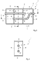
- the first or second passage opening 15 ', 16' in the first and second end floor 13 ', 14' may be provided (see. Fig. 3 ).
- FIGS. 1 . 3 and 5 shown two shelves 21, 21 ', each having a first and a second end portion 22, 23, 22', 23 ', wherein the first end portion 22, 22' on the first sandwich panel 6, 6 'and the second end portion 23, 23rd ', at the on the jacket hood 9 (see. Fig. 1 ) or on the second sandwich panel 10 '(cf. Fig. 4 ) is supported.
- the intermediate floors 21, 21 ' can be glued or soldered to the sandwich panels 6, 6', 10 'and welded to the jacket hood 9, to the sheet metal walls 11', 12 'and to the end floors 13, 14'.
- passage openings 24, 24' are provided in a region arranged between the first and second end sections, through which passages or discharge pipes 17, 18, 17 ', 18' are made. It is clear that in variants also a different number of intermediate floors may be provided in the muffler 1,1 '.
- the intermediate floors 21, 21 ' are formed as thin sheet metal walls.
- they can basically be designed either as a mechanically particularly stable sandwich panel or as a thin sheet-metal wall to be produced particularly inexpensively.
- combinations such that individual shelves 21, 21 'as a thin sheet metal wall and other shelves 21, 21' are formed as sandwich panels are conceivable.
- the at least one sandwich panel 6, 6 'or / and the at least one intermediate floor 21, 21' may be part of the self-supporting support structure 5.
- the jacket hood 9 for particularly stable attachment to the sandwich panel 6 in a longitudinal section profile of the muffler 1 may have two edge portions 25 which project outwardly away from the housing interior 4.
- the edge portions 25 of course also inwardly, the housing interior 4 out, stand out.
- the sandwich panel 6, 6 'in the longitudinal section profile of the muffler 1 have a first and second end portion 26 with respect to a longitudinal direction L of the muffler 1 in which a wall thickness D of the sandwich panel 6 is lower than D 1
- the end portions 26 may also be formed as folded portions which surround the edge portions 25 of the jacket hood 9.
- the jacket hood 9 can then additionally be fastened to the sandwich panel 6 by gluing or soldering.
- the edge portions 25 of the jacket hood 9 are formed as folded portions which engage around the end portions 26 of the sandwich panel 6.
- the sandwich panel 6 for the purpose of a particularly stable attachment to the jacket hood 9 in the region 25 or 26 riveted (see reference numeral 32 in the FIG. 6 ).
- the muffler 1 can be part of an exhaust system 27, in particular for an internal combustion engine of a motor vehicle, which in turn can be equipped with an exhaust gas exhaust pipe 30 for discharging exhaust gas from the exhaust system 27.
- the exhaust gas removal pipe 30 is fluidly connected to the supply pipe 17 of the muffler 1.
- the exhaust system 27 in turn may be part of an internal combustion engine 28 having a combustion chamber 29, wherein the combustion chamber 29 of the internal combustion engine 28 is fluidly connected to the exhaust system 27 by means of a connecting pipe 31.
Landscapes
- Engineering & Computer Science (AREA)
- Chemical & Material Sciences (AREA)
- Combustion & Propulsion (AREA)
- Mechanical Engineering (AREA)
- General Engineering & Computer Science (AREA)
- Exhaust Silencers (AREA)
Description
- Die vorliegende Erfindung betrifft einen Schalldämpfer für eine Abgasanlage einer Brennkraftmaschine, insbesondere eines Kraftfahrzeugs. Die Erfindung betrifft weiterhin eine Abgasanlage mit einem solchen Schalldämpfer sowie eine Brennkraftmaschine mit einer solchen Abgasanlage.
- Schalldämpfer umfassen üblicherweise ein Gehäuse, welches ein Schalldämpfervolumen umschließt, sowie zumindest ein Einlassrohr und wenigstens ein Auslassrohr. Über das Einlassrohr und das Auslassrohr ist der Schalldämpfer dann fluidisch an die übrige Abgasanlage anschließbar. Der Schalldämpfer kann außerdem zumindest ein Halteelement aufweisen, mit dem der Schalldämpfer an einer Haltestruktur, beispielsweise der Brennkraftmaschine eines Kraftfahrzeugs, befestigt werden kann. Bei Fahrzeuganwendungen ist es üblich, die Abgasanlage entlang eines Unterbodens des Kraftfahrzeugs zu verlegen. Da im Unterbodenbereich nur vergleichsweise wenig Einbauraum zur Verfügung steht, können Schalldämpfer vergleichsweise flach konzipiert werden, wobei ihr Gehäuse dann zumindest einen ebenen Wandbereich aufweisen kann, welcher im montierten Zustand beispielsweise dem Unterboden des Kraftfahrzeugs oder auch einer Fahrbahn zugewandt ist.
- Zur Reduzierung des Kraftstoffverbrauchs des den Schalldämpfer verwendenden Kraftfahrzeugs kann es sinnvoll sein, das Fahrzeuggewicht so weit wie möglich zu reduzieren. Folglich gibt es auch für den in einem Kraftfahrzeug verbauten Schalldämpfer einen Bedarf, diesen möglichst leicht und folglich mit reduzierten Wandstärken herzustellen. Hierbei sind Gehäuse problematisch, die wie oben erläutert zumindest einen ebenen Wandbereich besitzen. Denn je geringer die Wandstärke eines solchen ebenen Wandbereichs ist, desto größer ist die Neigung zur Schwingungsanregung, was zu störenden Geräuschen im Betrieb des Schalldämpfers sowie zu Beschädigungen, insbesondere mechanischer Befestigungsstellen, führen kann.
- Vor diesem Hintergrund offenbart die
GB 2 352 480 A - Die
WO 2012/055949 A1 behandelt einen Schalldämpfer, der ein Gehäuse mit einer Sandwichplatte aufweist, die einen Teil eines Gehäusemantels bildet. - Die vorliegende Erfindung beschäftigt sich mit dem Problem, für einen Schalldämpfer der eingangs genannten Art eine verbesserte Ausführungsform bereitzustellen, die sich insbesondere zur Realisierung einer Leichtbauweise eignet. Dieses Problem wird erfindungsgemäß durch den Gegenstand der unabhängigen Ansprüche gelöst. Vorteilhafte Ausführungsformen sind Gegenstand der abhängigen Ansprüche.
- Der erfindungsgemäße Schalldämpfer weist eine Sandwichplatte auf, wobei diese Sandwichplatte einen Teil eines Gehäusemantels des Gehäuses des Schalldämpfers ausbildet. Der Schalldämpfer weist ferner eine selbsttragende Tragstruktur auf, welche wiederum eine Rohranordnung umfasst, die wenigstens teilweise in dem Gehäuse-Innenraum angeordnet ist. Diese Rohranordnung kann beispielsweise eine Abgas-Zuführungsleitung und eine Abgas-Abführungsleitung umfassen, mittels welcher Abgas aus einer Abgasanlage einer Brennkraftmaschine einschließlich des zu bedämpfenden Schalls dem Schalldämpfer zugeführt und aus diesem wieder abgeführt werden kann. Mittels des erfindungsgemäßen Schalldämpfers können sowohl Kräfte als auch mechanische Biegemomente, welche von Abgasanlage der Brennkraftmaschine oder auch der Brennkraftmaschine selbst erzeugt werden, von der Rohranordnung aufgenommen und durch den Schalldämpfer hindurchgeleitet werden.
- Auf diese Weise kann eine unerwünschte Einleitung solcher Kräfte bzw. mechanischer Biegemomente in das eigentliche Gehäuse des Schalldämpfers vermieden werden, so dass dieses wiederum entsprechend dünnwandig ausgelegt werden kann. Mittels der selbsttragenden Tragstruktur kann die Rohranordnung dabei mechanisch stabil in dem Gehäuse des Schalldämpfers abgestützt werden.
- Von einer Zuführungsleitung der Rohranordnung dem Schalldämpfer zugeführte Kräfte bzw. Drehmomente werden also unmittelbar über die selbsttragende Tragstruktur an eine Abführungsleitung der Rohranordnung übertragen und somit wieder aus dem Schalldämpfer abgeführt, ohne dass das Gehäuse des Schalldämpfers selbst diese Kräfte aufnehmen muss. Zur Anbindung des Schalldämpfers an einen Unterboden eines Kraftfahrzeugs kann die erfindungsgemäße Sandwichplatte verwendet werden, welche zur optimalen Befestigung des Schalldämpfers an dem Unterboden flach ausgebildet ist und dennoch eine sehr hohe mechanische Stabilität aufweist. Somit lässt sich der erfindungsgemäße Schalldämpfer auch in dem in einem Kraftfahrzeug üblicherweise räumlich stark begrenzten Bauraum montieren und, falls erforderlich, hierfür entsprechend flach ausbilden. Da sich die Sandwichplatte aus mehreren (beispielweise 4 bis 5) einzelnen Blechwand-Lagen zusammensetzt, wobei jede solche Blechwand-Lage eine Dicke von ca. 0,1 mm aufweisen kann, ist das Gesamtgewicht einer solchen Sandwichplatte gegenüber herkömmlichen Blechwänden mit einer Blechwand-Dicke von ca. 1,5 mm deutlich reduziert und somit zur Aussteifung von großen Flächen besonders geeignet. Durch den Einsatz von Sandwichplatten in Schalldämpfern (anstelle von herkömmlichen Blechwänden) lässt sich also eine erhebliche Gewichtsersparnis erzielen. Der erfindungsgemäße Schalldämpfer kann folglich in Leichtbauweise hergestellt werden, wobei gleichzeitig sichergestellt ist, dass die für die Aufnahme und Übertragung von dem Schalldämpfer zugeführten Kräften bzw. mechanischen Biegemomenten notwendige mechanische Stabilität vorhanden ist.
- Erfindungsgemäß umfasst die selbsttragende Tragstruktur wenigstens einen Zwischenboden. Ein solcher Zwischenboden kann zur Abstützung der Rohranordnung an der selbsttragenden Tragstruktur verwendet werden und somit die mechanische Stabilität des Schalldämpfers weiter verbessern.
- Erfindungsgemäß ist die Sandwichplatte Teil der selbsttragenden Tragstruktur. Dies ermöglicht eine besonders gute Übertragung von dem Schalldämpfer zugeführten Kräften bzw. Drehmomenten über die selbsttragende Tragstruktur, beispielsweise an eine Abführungsleitung der Rohranordnung.
- Erfindungsgemäß umfasst der Schalldämpfer eine Mantelhaube, welche die Sandwichplatte zu dem Gehäusemantel des Gehäuses des erfindungsgemäßen Schalldämpfers komplettiert. Dies bedeutet, dass das gesamte Gehäuse des Schalldämpfers durch die Sandwichplatte und eine solche Mantelhaube gebildet wird. Dies ermöglicht einen mechanisch stabilen und dennoch technisch sehr einfach herzustellenden Schalldämpfer, so dass die Herstellungskosten eines solchen Schalldämpfers relativ gering gehalten werden können.
- In einer weiterbildenden Ausführungsform kann daran gedacht sein, dass der Schalldämpfer einen ersten und einen zweiten Endboden aufweist, welche den Gehäusemantel zu dem Gehäuse komplettieren. Hierzu kann der erste bzw. zweite Endboden jeweils mit dem Gehäusemantel verklebt, verlötet oder verschweißt sein, so dass der Gehäusemantel mit den beiden Endböden ein gasdichtes Gehäuse ausbildet. Da auch den beiden Endböden keine tragende Funktion zukommt, können auch diese vorzugsweise als dünne Blechwände ausgebildet sein. In einer besonders einfach herzustellenden und auch besonders leichtgewichtigen Ausführungsform kann die Mantelhaube integral mit dem ersten oder/und mit dem zweiten Endboden verbunden sein. Dies bedeutet, dass die Mantelhaube sowie der erste und zweite Endboden ein einziges Werkstück ausbilden, welches in der Art einer Haube mit der Sandwichplatte verbunden und insbesondere dieser verschweißt werden kann. Die mit dem ersten und zweiten Endboden integral verbundene Mantelhaube kann dabei in der Art einer Schale ausgebildet sein.
- Um eine mechanisch besonders stabile Befestigung der Mantelhaube an der Sandwichplatte sicherstellen zu können, kann in einer besonders bevorzugten Ausführungsform die Mantelhaube in einem Längsschnittsprofil des Schalldämpfers zwei Randabschnitte zur Anbringung an der wenigstens einen Sandwichplatte aufweisen, welche nach außen, vom Gehäuse-Innenraum des Schalldämpfers weg, oder nach innen, zum Gehäuse-Innenraum hin, abstehen.
- Für die effektive Einleitung des von dem erfindungsgemäßen Schalldämpfer zu bedämpfenden Schalls kann der erste oder/und zweite Endboden des Schalldämpfers jeweils eine erste bzw. zweite Durchgangsöffnung aufweisen. Die Rohanordnung kann dabei wenigstens einen Zuleitungs- und ein Ableitungsrohr mit einer Zuleitungs- bzw. Ableitungsöffnung umfassen, welche durch die erste bzw. zweite Durchgangsöffnung von außen in den Gehäuse-Innenraum durchgeführt sind, derart, dass die Zuleitungs- bzw. Ableitungsöffnung in der wenigstens einen Kammer des Schalldämpfers angeordnet ist.
- Um die mechanische Stabilität des erfindungsgemäßen Schalldämpfers weiter zu erhöhen, so dass dieser besonders hohe in den Schalldämpfer eingeleitete Kräfte bzw. Biegemomente aufnehmen kann, kann der wenigstens eine Zwischenboden einen ersten und einen zweiten Endabschnitt aufweisen, wobei sich der erste Endabschnitt dann an der ersten Sandwichplatte und der zweite Endabschnitt an der weiteren Sandwichplatte oder an der Mantelhaube abstützen kann. In dem Zwischenboden kann in einem zwischen den beiden Endabschnitten angeordneten Bereich wenigstens eine Durchgangsöffnung vorgesehen sein, durch welche das wenigstens eine Zuleitungs- oder Ableitungsrohr durchgeführt sein kann. Auf diese Weise kann das Zuleitungs- bzw. Ableitungsrohr mechanisch besonders stabil in dem Schalldämpfer abgestützt werden.
- In einer besonders bevorzugten Ausführungsform kann der wenigstens eine Zwischenboden eine zusätzliche Sandwichplatte (zusätzlich zu der ersten und zweiten Sandwichplatte) sein. In diesem Fall kann mittels der zusätzlichen Sandwichplatte eine besonders hohe mechanische Stabilität in dem erfindungsgemäßen Schalldämpfer erzielt werden. Alternativ kann der wenigstens ein Zwischenboden auch eine Blechwand sein. Diese Variante ist insbesondere dann vorzuziehen, wenn die mechanische Stabilität nicht mittels des Zwischenbodens wesentlich erhöht werden muss, so dass die Blechwand beispielsweise als reine Trennwand zur Auftrennung der Kammer in dem Gehäuse-Innenraum in eine erste und zweite Unterkammer dienen kann, mittels welcher in den Schalldämpfer eingeleiteter Schall besonders gut gedämpft werden kann.
- In einer besonders einfachen und kostengünstig herzustellenden Ausführungsform kann die Sandwichplatte mit der weiteren Sandwichplatte bzw. der Mantelhaube mittels Verschweißen, Verkleben oder Verlöten verbunden sein.
- Um die Sandwichplatte besonders gut an der Mantelhaube befestigen zu können, kann die wenigstens eine Sandwichplatte in einem Längsschnittprofil des Schalldämpfers einen bezüglich der Längsrichtung ersten und zweiten Endabschnitt aufweisen, in welchem eine Wanddicke der Sandwichplatte einen geringeren Wert aufweist als in einem zwischen den beiden Endabschnitten angeordneten Bereich der Sandwichplatte. Die Sandwichplatte kann dann an den beiden Endabschnitten mit zu diesen beiden Endabschnitten komplementären Randabschnitten der Mantelhaube vernietet sein.
- Die Erfindung betrifft des Weiteren eine Abgasanlage, insbesondere für eine Brennkraftmaschine eines Kraftfahrzeugs, mit einem Abgas-Abführungsrohr zum Abführen von Abgas aus der Abgasanlage sowie mit einem Schalldämpfer mit einem oder mehreren der vorhergehend genannten Merkmale. Die Rohranordnung des Schalldämpfers kann dabei ein fluidisch mit dem Abgas-Abführungsrohr verbundenes Zuführungsrohr aufweisen.
- Die vorliegende Erfindung betrifft des Weiteren eine Brennkraftmaschine mit einem Brennraum sowie einer Abgasanlage mit einem oder mehreren der vorhergehend genannten Merkmale, wobei der Brennraum der Brennkraftmaschine mittels eines Verbindungsrohrs fluidisch mit der Abgasanlage verbunden sein kann.
- Weitere wichtige Merkmale und Vorteile der Erfindung ergeben sich aus den Unteransprüchen, aus den Zeichnungen und aus der zugehörigen Figurenbeschreibung anhand der Zeichnungen.
- Ein bevorzugtes Ausführungsbeispiel der Erfindung ist in den Zeichnungen dargestellt und wird in der nachfolgenden Beschreibung näher erläutert.
- Es zeigen, jeweils schematisch:
- Fig. 1
- ein erstes Ausführungsbeispiel eines erfindungsgemäßen Schalldämpfers in einer Längsschnittansicht,
- Fig. 2
- den Schalldämpfer der
Figur 1 in einer Seitenansicht, - Fig. 3
- eine nicht zur Erfindung gehörige Variante des Ausführungsbeispiels der
Figur 1 , - Fig. 4
- eine Schnittansicht des Schalldämpfers der
Figur 3 gemäß der Linie IV-IV, - Fig. 5
- eine Schnittansicht des Schalldämpfers der
Figur 3 gemäß der Linie V-V, - Fig. 6
- eine Teilansicht der
Figur 1 , - Fig. 7
- eine Variante der
Figur 6 , - Fig. 8
- den erfindungsgemäßen Schalldämpfer als Teil einer Abgasanlage bzw. einer Brennkraftmaschine in einer grobschematischen Darstellung.
- In den
Figuren 1 und 2 ist ein erfindungsgemäßer Schalldämpfer dargestellt und mit 1 bezeichnet. DieFigur 1 zeigt den Schalldämpfer 1 dabei in einer Längsschnittansicht, dieFigur 2 in einer Seitenansicht. - Der Schalldämpfer 1 umfasst ein Gehäuse 2, welches einen sich in eine Umfangsrichtung U des Gehäuses erstreckenden Gehäusemantel 3 aufweist. Der Schalldämpfer 1 umfasst ferner einen wenigstens eine Kammer 8 aufweisenden Gehäuse-Innenraum 4, welcher von dem Gehäuse 2 umschlossen ist, sowie eine selbsttragende Tragstruktur 5 und eine Sandwichplatte 6. Die Sandwichplatte 6 bildet dabei einen Teil des Gehäusemantels 3 aus. Die selbsttragende Tragstruktur 5 umfasst eine Rohranordnung 7, welche teilweise in dem Gehäuse-Innenraum 4 angeordnet ist. Der Schalldämpfer 1 umfasst ferner eine Mantelhaube 9, welche die erste Sandwichplatte 6 zum Gehäusemantel 3 komplettiert (vgl.
Figur 2 ). Die Sandwichplatte 6 kann mit der Mantelhaube 9 mittels Verschweißen, Verkleben oder Verlöten verbunden sein. - Betrachtet man die Darstellung der
Figur 2 , so erkennt man, dass die Mantelhaube 9 aufgrund ihrer schalenartigen Ausbildung die Sandwichplatte 6 nicht nur zu dem Gehäusemantel 3, sondern zu dem gesamten Gehäuse 2 komplettiert. Dies bedeutet insbesondere, dass zur Komplettierung des Gehäusemantels 3 keine zusätzlichen Endböden erforderlich sind, was den Aufbau und damit die Herstellung des erfindungsgemäßen Schalldämpfers 1 stark vereinfacht. In einer alternativen Betrachtungsweise kann man die Mantelhaube 9 auch als integral mit einem ersten und zweiten Endboden verbunden ansehen. - In einer in der
Figur 3 gezeigten, nicht zur Erfindung gehörigen Variante des Ausführungsbeispiels derFigur 1 kann der Schalldämpfer 1' alternativ zu der Mantelhaube 9 eine weitere Sandwichplatte 10', welche Teil der selbsttragenden Tragstruktur ist, sowie eine erste und eine zweite Blechwand 11', 12' umfassen. Diese komplettieren dann zusammen die erste Sandwichplatte 6' zu dem Gehäusemantel 3'. DieFigur 4 zeigt den Schalldämpfer 1' derFigur 3 gemäß der Schnittlinie IV, und dieFigur 5 zeigt den Schalldämpfer 1' gemäß der Schnittlinie V. - Die Sandwichplatte 6' und die weitere Sandwichplatte 10' sowie die erste und zweite Blechwand 11', 12' können in dem Querschnittsprofil des Schalldämpfers 1' vorzugweise im Wesentlichen gegenüberliegend zueinander angeordnet sein. Grundsätzlich sind in weiteren Varianten aber auch andere Anordnungs-Geometrien vorstellbar.
- In der Variante gemäß den
Figuren 3 bis 5 , die nicht die Erfindung wiedergibt, bilden die erste und zweite Blechwand 11', 12' gleichzeitig auch einen ersten und einen zweiten Endboden 13', 14' aus, welche den Gehäusemantel 3' zu dem Gehäuse 2' komplettieren, d.h. die Blechwände 11', 12' und die Endböden 13', 14' sind integral miteinander verbunden und bilden eine rahmenartige Struktur in der Art eines umlaufenden U-Profils (vgl.Fig. 4 und5 ) aus. In einer Variante können die Blechwände 11', 12' und die Endböden 13', 14' aber auch jeweils separat ausgebildet und miteinander verschweißt sein. Die Endböden 13', 14' bzw. die Blechwände 11', 12' können mit den Sandwichplatten 6', 10' verklebt oder verlötet sein. - Betrachtet man nun wieder die Darstellung der
Figuren 1 und 2 , so erkennt man, dass der Mantelboden 9 eine erste bzw. zweite Durchgangsöffnung 15, 16 aufweist, und dass die Rohrstruktur 7 des Schalldämpfers 1 ein Zuleitungs- und ein Ableitungsrohr 17, 18 mit einer Zuleitungs- bzw. Ableitungsöffnung 19, 20 umfasst, welche durch die erste bzw. zweite Durchgangsöffnung 15, 16 von außen in den Gehäuse-Innenraum 4 durchgeführt sind. Die Zuleitungs- bzw. Ableitungsöffnung 19, 20 ist dabei in der Kammer 8 angeordnet. Entsprechendes gilt mutatis mutandis für die Variante des Ausführungsbeispiels gemäß denFiguren 3 bis 5 . In diesem Fall kann die erste bzw. zweite Durchgangsöffnung 15', 16' in dem ersten bzw. zweiten Endboden 13', 14' vorgesehen sein (vgl.Fig. 3 ). - Zur weiteren Verbesserung der mechanischen Stabilität kann der Schalldämpfer 1, 1' wie in den
Figuren 1 ,3 und5 gezeigt zwei Zwischenböden 21, 21' mit jeweils einem ersten und einem zweiten Endabschnitt 22, 23, 22', 23' aufweisen, wobei sich der erste Endabschnitt 22, 22' an der ersten Sandwichplatte 6, 6' und der zweite Endabschnitt 23, 23', an der an der Mantelhaube 9 (vgl.Fig. 1 ) oder an der zweiten Sandwichplatte 10' (vgl.Fig. 4 ) abstützt. Die Zwischenböden 21, 21' können mit den Sandwichplatten 6, 6', 10', verklebt oder verlötet und mit der Mantelhaube 9, mit den Blechwänden 11', 12' und mit den Endböden 13, 14' verschweißt sein. - In den beiden Zwischenböden 21, 21' sind in einem zwischen dem ersten und zweiten Endabschnitt angeordneten Bereich Durchgangsöffnungen 24, 24' vorgesehen, durch welche das Zuleitungs- bzw. Ableitungsrohr 17, 18, 17', 18' durchgeführt sind. Es ist klar, dass in Varianten auch eine andere Anzahl an Zwischenböden in dem Schalldämpfer 1,1' vorgesehen sein kann.
- In der Darstellung der
Figuren 1 ,3 und5 sind die Zwischenböden 21, 21' als dünne Blechwände ausgebildet. Je nachdem, welche zusätzliche mechanische Versteifung mittels der zusätzlichen Zwischenböden 21, 21' erzielt werden soll, können diese grundsätzlich entweder als mechanisch besonders stabile Sandwichplatte oder als besonders kostengünstig herzustellende dünne Blechwand ausgebildet sein. Auch Kombinationen, derart, dass einzelne Zwischenböden 21, 21' als dünne Blechwand und weitere Zwischenböden 21, 21' als Sandwichplatten ausgebildet sind, sind vorstellbar. - In Varianten des Ausführungsbeispiels können die wenigstens eine Sandwichplatte 6, 6' oder/und der wenigstens eine Zwischenboden 21, 21' Teil der selbsttragenden Tragstruktur 5 sein.
- Aus der Darstellung der
Figur 1 lässt sich entnehmen, dass die Mantelhaube 9 zur besonders stabilen Befestigung an der Sandwichplatte 6 in einem Längsschnittprofil des Schalldämpfers 1 zwei Randabschnitte 25 aufweisen kann, welche nach außen, vom Gehäuse-Innenraum 4 weg, abstehen. In einer alternativen Variante können die Randabschnitte 25 selbstverständlich auch nach innen, zum Gehäuse-Innenraum 4 hin, abstehen. - Alternativ oder zusätzlich kann die Sandwichplatte 6, 6' in dem Längsschnittprofil des Schalldämpfers 1 einen bezüglich einer Längsrichtung L des Schalldämpfers 1 ersten und zweiten Endabschnitt 26 aufweisen, in welchem eine Wanddicke D der Sandwichplatte 6 einen geringeren Wert D1 aufweist als in einem zwischen den beiden Endabschnitten 26 angeordneten Bereich der Sandwichplatte 6. Dies ist grobschematisch in der Darstellung der
Figur 6 dargestellt, welche die Sandwichplatte 6 mit einem Endabschnitt 26 zeigt. In einer Variante können die Endabschnitte 26 auch als Falzabschnitte ausgebildet sein, welche die Randabschnitte 25 der Mantelhaube 9 umgreifen. Dies ist grobschematisch in derFigur 7 gezeigt. Im Bereich der Endabschnitte 26 kann dann die Mantelhaube 9 an der Sandwichplatte 6 zusätzlich mittels Verkleben oder Verlöten befestigt sein. Alternativ ist es selbstverständlich auch vorstellbar, dass die Randabschnitte 25 der Mantelhaube 9 als Falzabschnitte ausgebildet sind, welche die Endabschnitte 26 der Sandwichplatte 6 umgreifen. - Wie sich der Darstellung der
Figur 6 entnehmen lässt, kann die Sandwichplatte 6 zum Zwecke einer besonders stabilen Befestigung mit der Mantelhaube 9 im Bereich 25 bzw. 26 vernietet sein (vgl. Bezugszeichen 32 in derFigur 6 ). - In der grobschematischen Darstellung der
Figur 8 ist gezeigt, dass der Schalldämpfer 1 Teil einer Abgasanlage 27, insbesondere für eine Brennkraftmaschine eines Kraftfahrzeugs, sein kann, welche wiederum mit einem Abgas-Abführungsrohr 30 zum Abführen von Abgas aus der Abgasanlage 27 ausgestattet sein kann. Das Abgas-Abführungsrohr 30 ist dabei mit dem Zuleitungsrohr 17 des Schalldämpfers 1 fluidisch verbunden. Die Abgasanlage 27 wiederum kann Teil einer Brennkraftmaschine 28 mit einem Brennraum 29 sein, wobei der Brennraum 29 der Brennkraftmaschine 28 mittels eines Verbindungsrohrs 31 fluidisch mit der Abgasanlage 27 verbunden ist.
Claims (6)
- Schalldämpfer (1) für eine Abgasanlage einer Brennkraftmaschine, insbesondere eines Kraftfahrzeugs,- mit einem Gehäuse (2), welches einen sich in eine Umfangsrichtung (U) des Gehäuses (2) erstreckenden Gehäusemantel (3) aufweist,- mit einer Sandwichplatte (6), welche einen Teil des Gehäusemantels (3) ausbildet,- mit einem wenigstens eine Kammer (8) aufweisenden Gehäuse-Innenraum (4), welcher von dem Gehäuse (2) umschlossen ist,- mit einer selbsttragenden Tragstruktur (5), welche eine wenigstens teilweise in dem Gehäuse-Innenraum (4) angeordnete Rohranordnung (7) umfasst,- wobei die selbsttragende Tragstruktur (5) wenigstens einen Zwischenboden (21) umfasst,- die wenigstens eine Sandwichplatte (6) Teil der selbsttragenden Tragstruktur (5) ist,dadurch gekennzeichnet, dass
der Schalldämpfer (1) eine Mantelhaube (9) umfasst, welche die Sandwichplatte (6) zum Gehäusemantel (3) komplettiert. - Schalldämpfer (1) nach einem der vorhergehenden Ansprüche,
dadurch gekennzeichnet, dass
die Mantelhaube (9) in einem Längsschnittprofil des Schalldämpfers (1) zwei Randabschnitte (25) zur Anbringung an der wenigstens einen Sandwichplatte (6) aufweist, welche nach außen, vom Gehäuse-Innenraum (4) weg, oder nach innen, zum Gehäuse-Innenraum (4) hin, abstehen. - Schalldämpfer (1) nach einem der vorhergehenden Ansprüche,
dadurch gekennzeichnet, dass
der wenigstens eine Zwischenboden (21) eine zusätzliche Sandwichplatte oder eine Blechwand ist. - Schalldämpfer (1) nach einem der vorhergehenden Ansprüche,
dadurch gekennzeichnet, dass- die wenigstens eine Sandwichplatte (6) in einem Längsschnittprofil des Schalldämpfers (1) einen bezüglich der Längsrichtung (L) ersten und zweiten Endabschnitt aufweist (26), in welchem eine Wanddicke (D) der Sandwichplatte (6) einen geringeren Wert (D1) aufweist als in einem zwischen den beiden Endabschnitten (26) angeordneten Bereich der Sandwichplatte (6),- die wenigstens eine Sandwichplatte (6) an den beiden Endabschnitten (26) mit zu diesen beiden Endabschnitten (26) komplementären Randabschnitten (25) der Mantelhaube (9) vernietet ist. - Abgasanlage (27), insbesondere für eine Brennkraftmaschine (28) eines Kraftfahrzeugs,- mit einem Abgas-Abführungsrohr (30) zum Abführen von Abgas aus der Abgasanlage (27),- mit einem Schalldämpfer (1) nach einem der vorhergehenden Ansprüche,- wobei die Rohranordnung (7) ein fluidisch mit dem Abgas-Abführungsrohr (30) verbundenes Zuführungsrohr (17) aufweist.
- Brennkraftmaschine (28),- mit einem Brennraum (29),- mit einer Abgasanlage (27) nach Anspruch 5,- wobei der Brennraum (29) mittels eines Verbindungsrohrs (31) fluidisch mit der Abgasanlage (27) verbunden ist.
Applications Claiming Priority (1)
| Application Number | Priority Date | Filing Date | Title |
|---|---|---|---|
| DE102012209932A DE102012209932A1 (de) | 2012-06-13 | 2012-06-13 | Leichtbau-Schalldämpfer |
Publications (2)
| Publication Number | Publication Date |
|---|---|
| EP2674585A1 EP2674585A1 (de) | 2013-12-18 |
| EP2674585B1 true EP2674585B1 (de) | 2016-09-07 |
Family
ID=48537858
Family Applications (1)
| Application Number | Title | Priority Date | Filing Date |
|---|---|---|---|
| EP13170271.4A Active EP2674585B1 (de) | 2012-06-13 | 2013-06-03 | Leichtbau-Schalldämpfer |
Country Status (5)
| Country | Link |
|---|---|
| US (1) | US9163547B2 (de) |
| EP (1) | EP2674585B1 (de) |
| JP (1) | JP5770220B2 (de) |
| CN (1) | CN103485863B (de) |
| DE (1) | DE102012209932A1 (de) |
Families Citing this family (5)
| Publication number | Priority date | Publication date | Assignee | Title |
|---|---|---|---|---|
| AU2017244041B2 (en) | 2016-03-30 | 2022-12-01 | Marine Canada Acquisition Inc. | Vehicle heater and controls therefor |
| CN106246294A (zh) * | 2016-10-14 | 2016-12-21 | 上海天纳克排气系统有限公司 | 消声器 |
| US20200173320A1 (en) | 2017-09-25 | 2020-06-04 | Faurecia Emissions Control Technologies, Usa, Llc | Acoustic volume in hot-end of exhaust systems |
| US10941693B2 (en) | 2018-01-18 | 2021-03-09 | Faurecia Emissions Control Technologies, Usa, Llc | Vehicle frame with acoustic volume for an exhaust system |
| FR3143665A1 (fr) * | 2022-12-19 | 2024-06-21 | Renault S.A.S | Volume acoustique d’échappement d’un véhicule automobile comportant un écran thermique |
Family Cites Families (24)
| Publication number | Priority date | Publication date | Assignee | Title |
|---|---|---|---|---|
| FR2480350A1 (fr) * | 1980-04-09 | 1981-10-16 | Letang & Remy Ets | Silencieux pour pot d'echappement en acier inoxydable |
| US4909348A (en) * | 1988-01-20 | 1990-03-20 | Ap Parts Manufacturing Company | Stamp formed exhaust muffler with conformal outer shell |
| US4860853A (en) * | 1988-12-20 | 1989-08-29 | Ap Parts Manufacturing Company | Stamp formed muffler with nonplanar array of tubes |
| JPH03160109A (ja) * | 1989-11-15 | 1991-07-10 | Yukio Sugiki | 多層合鋼板を用いた排気機関 |
| US5597986A (en) * | 1995-02-27 | 1997-01-28 | Ap Parts Manufacturing Company | Stamp formed muffler with nested chambers |
| JPH09242526A (ja) | 1996-03-07 | 1997-09-16 | Yamaha Motor Co Ltd | 自動二輪車用マフラー |
| US5859394A (en) * | 1997-06-12 | 1999-01-12 | Ap Parts Manufacturing Company | Muffler with stamped internal plates defining tubes and separating chambers |
| US5739484A (en) * | 1997-03-12 | 1998-04-14 | Jones; Mack L. | Exhaust muffler |
| US6199659B1 (en) * | 1998-03-05 | 2001-03-13 | Arvin Industries, Inc. | Stamp-formed muffler |
| US6164412A (en) * | 1998-04-03 | 2000-12-26 | Arvin Industries, Inc. | Muffler |
| US6659222B1 (en) * | 1999-03-05 | 2003-12-09 | Arvinmeritor, Inc. | Multi-chambered muffler |
| MY125806A (en) * | 1999-07-23 | 2006-08-30 | Perusahaan Otomobil Nasional Berhad | Exhaust noise suppressor |
| DE10060522B4 (de) * | 2000-12-06 | 2004-07-22 | J. Eberspächer GmbH & Co. KG | Abgas-Schalldämpfer für ein brennstoffbetriebenes Heizgerät |
| DE10106559A1 (de) * | 2001-02-13 | 2002-08-29 | Eberspaecher J Gmbh & Co | Abgas-Gehäuseteil eines Kraftfahrzeuges |
| US7273129B2 (en) * | 2003-09-05 | 2007-09-25 | Faurecia Exhaust Systems, Inc. | Muffler with internal heat shield |
| JP2005155366A (ja) | 2003-11-21 | 2005-06-16 | Toyota Motor Corp | マフラ |
| JP2006063849A (ja) | 2004-08-25 | 2006-03-09 | Calsonic Kansei Corp | 車両用消音器における排気管の固定構造及び方法 |
| FR2916477B1 (fr) * | 2007-05-25 | 2010-04-16 | Faurecia Sys Echappement | Volume d'echappement pour une ligne d'echappement de vehicule automobile |
| CN201092874Y (zh) * | 2007-08-15 | 2008-07-30 | 王建亮 | 一种发动机消音器 |
| DE102008006401A1 (de) * | 2008-01-28 | 2009-07-30 | Benteler Automobiltechnik Gmbh | Verfahren zur Herstellung eines Abgasschalldämpfers und Abgasschalldämpfer |
| DE102008056350B4 (de) * | 2008-11-07 | 2016-01-07 | Eberspächer Exhaust Technology GmbH & Co. KG | Schalldämpfer und zugehöriges Herstellungsverfahren |
| US7942240B2 (en) * | 2009-06-08 | 2011-05-17 | Honda Motor Co., Ltd. | Silencer for internal combustion engine |
| AT510788B1 (de) * | 2010-10-28 | 2012-10-15 | Avl List Gmbh | Abgasschalldämpferanordnung |
| DE102011007856A1 (de) * | 2011-04-21 | 2012-10-25 | J. Eberspächer GmbH & Co. KG | Schalldämpfer |
-
2012
- 2012-06-13 DE DE102012209932A patent/DE102012209932A1/de not_active Ceased
-
2013
- 2013-06-03 EP EP13170271.4A patent/EP2674585B1/de active Active
- 2013-06-08 CN CN201310229624.6A patent/CN103485863B/zh active Active
- 2013-06-12 US US13/916,131 patent/US9163547B2/en active Active
- 2013-06-13 JP JP2013124526A patent/JP5770220B2/ja active Active
Also Published As
| Publication number | Publication date |
|---|---|
| US9163547B2 (en) | 2015-10-20 |
| CN103485863A (zh) | 2014-01-01 |
| JP2013256953A (ja) | 2013-12-26 |
| CN103485863B (zh) | 2016-12-28 |
| JP5770220B2 (ja) | 2015-08-26 |
| EP2674585A1 (de) | 2013-12-18 |
| DE102012209932A1 (de) | 2013-12-19 |
| US20130333977A1 (en) | 2013-12-19 |
Similar Documents
| Publication | Publication Date | Title |
|---|---|---|
| EP2674585B1 (de) | Leichtbau-Schalldämpfer | |
| DE602005001519T2 (de) | Lärmminderungsanordnung für Fluggasturbine | |
| DE102011077183B4 (de) | Schalldämpfer und Herstellungsverfahren | |
| DE102008056350B4 (de) | Schalldämpfer und zugehöriges Herstellungsverfahren | |
| EP2196640B1 (de) | Schalldämpfer | |
| EP1843018A1 (de) | Schalldämpfer | |
| EP2514941B1 (de) | Schalldämpfer | |
| EP2639423B1 (de) | Schalldämpfer-einheit | |
| DE3147298A1 (de) | "antriebsaggregat" | |
| DE102006055560A1 (de) | Karosseriebauteil für einen Kraftwagen | |
| DE10247492A1 (de) | Kraftfahrzeugkarosserie | |
| DE102009056815B4 (de) | Schalldämpfer für Abgasanlagen und Verfahren zur Vermeidung oder Verminderung von Störgeräuschen bei Schalldämpfern | |
| DE102014110101A1 (de) | Schalldämpfer | |
| EP0056604A2 (de) | Abgasschalldämpfer für Brennkraftmaschinen und Verfahren zu dessen Herstellung | |
| DE102016209317A1 (de) | Hybridantriebssystem, elektrisches Antriebsmodul und deren Kühlanordnung | |
| AT505344B1 (de) | Lagerung eines vorderachsgetriebes bei einem kraftfahrzeug | |
| DE102009004165B4 (de) | Verfahren zum Aufbau einer Bodengruppe eines Nutzfahrzeug-Fahrerhauses und Boden-Mittenmodul | |
| DE10325381B3 (de) | Getriebestütze zur Lagerung eines Getriebes und Getriebe mit derartiger Getriebestütze | |
| WO2004033274A1 (de) | Stirnwand für ein kraftfahrzeug | |
| DE102005054960B4 (de) | Motorraumabdeckungsbauteil für eine Kraftfahrzeug-Karosserie und Rohbaustruktur einer Kraftfahrzeugkarosserie | |
| EP3823853A1 (de) | Vorrichtung zur motorlagerung | |
| DE102004042110B3 (de) | Schalldämpfer für eine Abgasanlage | |
| EP1691050B1 (de) | Schalldämpfer | |
| DE102019120003A1 (de) | Fahrzeugkomponente, insbesondere Fahrzeugheck | |
| DE102006016782B4 (de) | System umfassend ein erstes Lagerungselement zur Aufnahme einer Kurbelwelle und ein zweites Lagerungselement zur Aufnahme von mindestens zwei Getriebewellen |
Legal Events
| Date | Code | Title | Description |
|---|---|---|---|
| PUAI | Public reference made under article 153(3) epc to a published international application that has entered the european phase |
Free format text: ORIGINAL CODE: 0009012 |
|
| AK | Designated contracting states |
Kind code of ref document: A1 Designated state(s): AL AT BE BG CH CY CZ DE DK EE ES FI FR GB GR HR HU IE IS IT LI LT LU LV MC MK MT NL NO PL PT RO RS SE SI SK SM TR |
|
| AX | Request for extension of the european patent |
Extension state: BA ME |
|
| 17P | Request for examination filed |
Effective date: 20140505 |
|
| RBV | Designated contracting states (corrected) |
Designated state(s): AL AT BE BG CH CY CZ DE DK EE ES FI FR GB GR HR HU IE IS IT LI LT LU LV MC MK MT NL NO PL PT RO RS SE SI SK SM TR |
|
| 17Q | First examination report despatched |
Effective date: 20150813 |
|
| GRAP | Despatch of communication of intention to grant a patent |
Free format text: ORIGINAL CODE: EPIDOSNIGR1 |
|
| INTG | Intention to grant announced |
Effective date: 20160322 |
|
| GRAS | Grant fee paid |
Free format text: ORIGINAL CODE: EPIDOSNIGR3 |
|
| GRAA | (expected) grant |
Free format text: ORIGINAL CODE: 0009210 |
|
| AK | Designated contracting states |
Kind code of ref document: B1 Designated state(s): AL AT BE BG CH CY CZ DE DK EE ES FI FR GB GR HR HU IE IS IT LI LT LU LV MC MK MT NL NO PL PT RO RS SE SI SK SM TR |
|
| REG | Reference to a national code |
Ref country code: GB Ref legal event code: FG4D Free format text: NOT ENGLISH |
|
| REG | Reference to a national code |
Ref country code: CH Ref legal event code: EP |
|
| REG | Reference to a national code |
Ref country code: IE Ref legal event code: FG4D Free format text: LANGUAGE OF EP DOCUMENT: GERMAN |
|
| REG | Reference to a national code |
Ref country code: AT Ref legal event code: REF Ref document number: 827089 Country of ref document: AT Kind code of ref document: T Effective date: 20161015 |
|
| REG | Reference to a national code |
Ref country code: DE Ref legal event code: R096 Ref document number: 502013004329 Country of ref document: DE |
|
| REG | Reference to a national code |
Ref country code: SE Ref legal event code: TRGR |
|
| REG | Reference to a national code |
Ref country code: LT Ref legal event code: MG4D |
|
| REG | Reference to a national code |
Ref country code: NL Ref legal event code: MP Effective date: 20160907 |
|
| PG25 | Lapsed in a contracting state [announced via postgrant information from national office to epo] |
Ref country code: RS Free format text: LAPSE BECAUSE OF FAILURE TO SUBMIT A TRANSLATION OF THE DESCRIPTION OR TO PAY THE FEE WITHIN THE PRESCRIBED TIME-LIMIT Effective date: 20160907 Ref country code: HR Free format text: LAPSE BECAUSE OF FAILURE TO SUBMIT A TRANSLATION OF THE DESCRIPTION OR TO PAY THE FEE WITHIN THE PRESCRIBED TIME-LIMIT Effective date: 20160907 Ref country code: NO Free format text: LAPSE BECAUSE OF FAILURE TO SUBMIT A TRANSLATION OF THE DESCRIPTION OR TO PAY THE FEE WITHIN THE PRESCRIBED TIME-LIMIT Effective date: 20161207 Ref country code: LT Free format text: LAPSE BECAUSE OF FAILURE TO SUBMIT A TRANSLATION OF THE DESCRIPTION OR TO PAY THE FEE WITHIN THE PRESCRIBED TIME-LIMIT Effective date: 20160907 Ref country code: FI Free format text: LAPSE BECAUSE OF FAILURE TO SUBMIT A TRANSLATION OF THE DESCRIPTION OR TO PAY THE FEE WITHIN THE PRESCRIBED TIME-LIMIT Effective date: 20160907 |
|
| PG25 | Lapsed in a contracting state [announced via postgrant information from national office to epo] |
Ref country code: NL Free format text: LAPSE BECAUSE OF FAILURE TO SUBMIT A TRANSLATION OF THE DESCRIPTION OR TO PAY THE FEE WITHIN THE PRESCRIBED TIME-LIMIT Effective date: 20160907 Ref country code: ES Free format text: LAPSE BECAUSE OF FAILURE TO SUBMIT A TRANSLATION OF THE DESCRIPTION OR TO PAY THE FEE WITHIN THE PRESCRIBED TIME-LIMIT Effective date: 20160907 Ref country code: LV Free format text: LAPSE BECAUSE OF FAILURE TO SUBMIT A TRANSLATION OF THE DESCRIPTION OR TO PAY THE FEE WITHIN THE PRESCRIBED TIME-LIMIT Effective date: 20160907 Ref country code: GR Free format text: LAPSE BECAUSE OF FAILURE TO SUBMIT A TRANSLATION OF THE DESCRIPTION OR TO PAY THE FEE WITHIN THE PRESCRIBED TIME-LIMIT Effective date: 20161208 |
|
| PG25 | Lapsed in a contracting state [announced via postgrant information from national office to epo] |
Ref country code: EE Free format text: LAPSE BECAUSE OF FAILURE TO SUBMIT A TRANSLATION OF THE DESCRIPTION OR TO PAY THE FEE WITHIN THE PRESCRIBED TIME-LIMIT Effective date: 20160907 Ref country code: RO Free format text: LAPSE BECAUSE OF FAILURE TO SUBMIT A TRANSLATION OF THE DESCRIPTION OR TO PAY THE FEE WITHIN THE PRESCRIBED TIME-LIMIT Effective date: 20160907 |
|
| PG25 | Lapsed in a contracting state [announced via postgrant information from national office to epo] |
Ref country code: SK Free format text: LAPSE BECAUSE OF FAILURE TO SUBMIT A TRANSLATION OF THE DESCRIPTION OR TO PAY THE FEE WITHIN THE PRESCRIBED TIME-LIMIT Effective date: 20160907 Ref country code: PT Free format text: LAPSE BECAUSE OF FAILURE TO SUBMIT A TRANSLATION OF THE DESCRIPTION OR TO PAY THE FEE WITHIN THE PRESCRIBED TIME-LIMIT Effective date: 20170109 Ref country code: BG Free format text: LAPSE BECAUSE OF FAILURE TO SUBMIT A TRANSLATION OF THE DESCRIPTION OR TO PAY THE FEE WITHIN THE PRESCRIBED TIME-LIMIT Effective date: 20161207 Ref country code: PL Free format text: LAPSE BECAUSE OF FAILURE TO SUBMIT A TRANSLATION OF THE DESCRIPTION OR TO PAY THE FEE WITHIN THE PRESCRIBED TIME-LIMIT Effective date: 20160907 Ref country code: CZ Free format text: LAPSE BECAUSE OF FAILURE TO SUBMIT A TRANSLATION OF THE DESCRIPTION OR TO PAY THE FEE WITHIN THE PRESCRIBED TIME-LIMIT Effective date: 20160907 Ref country code: SM Free format text: LAPSE BECAUSE OF FAILURE TO SUBMIT A TRANSLATION OF THE DESCRIPTION OR TO PAY THE FEE WITHIN THE PRESCRIBED TIME-LIMIT Effective date: 20160907 Ref country code: IS Free format text: LAPSE BECAUSE OF FAILURE TO SUBMIT A TRANSLATION OF THE DESCRIPTION OR TO PAY THE FEE WITHIN THE PRESCRIBED TIME-LIMIT Effective date: 20170107 |
|
| REG | Reference to a national code |
Ref country code: DE Ref legal event code: R097 Ref document number: 502013004329 Country of ref document: DE |
|
| REG | Reference to a national code |
Ref country code: FR Ref legal event code: PLFP Year of fee payment: 5 |
|
| PLBE | No opposition filed within time limit |
Free format text: ORIGINAL CODE: 0009261 |
|
| STAA | Information on the status of an ep patent application or granted ep patent |
Free format text: STATUS: NO OPPOSITION FILED WITHIN TIME LIMIT |
|
| PG25 | Lapsed in a contracting state [announced via postgrant information from national office to epo] |
Ref country code: DK Free format text: LAPSE BECAUSE OF FAILURE TO SUBMIT A TRANSLATION OF THE DESCRIPTION OR TO PAY THE FEE WITHIN THE PRESCRIBED TIME-LIMIT Effective date: 20160907 |
|
| 26N | No opposition filed |
Effective date: 20170608 |
|
| PG25 | Lapsed in a contracting state [announced via postgrant information from national office to epo] |
Ref country code: SI Free format text: LAPSE BECAUSE OF FAILURE TO SUBMIT A TRANSLATION OF THE DESCRIPTION OR TO PAY THE FEE WITHIN THE PRESCRIBED TIME-LIMIT Effective date: 20160907 |
|
| PG25 | Lapsed in a contracting state [announced via postgrant information from national office to epo] |
Ref country code: MC Free format text: LAPSE BECAUSE OF FAILURE TO SUBMIT A TRANSLATION OF THE DESCRIPTION OR TO PAY THE FEE WITHIN THE PRESCRIBED TIME-LIMIT Effective date: 20160907 |
|
| REG | Reference to a national code |
Ref country code: CH Ref legal event code: PL |
|
| REG | Reference to a national code |
Ref country code: IE Ref legal event code: MM4A |
|
| PG25 | Lapsed in a contracting state [announced via postgrant information from national office to epo] |
Ref country code: CH Free format text: LAPSE BECAUSE OF NON-PAYMENT OF DUE FEES Effective date: 20170630 Ref country code: IE Free format text: LAPSE BECAUSE OF NON-PAYMENT OF DUE FEES Effective date: 20170603 Ref country code: LU Free format text: LAPSE BECAUSE OF NON-PAYMENT OF DUE FEES Effective date: 20170603 Ref country code: LI Free format text: LAPSE BECAUSE OF NON-PAYMENT OF DUE FEES Effective date: 20170630 |
|
| REG | Reference to a national code |
Ref country code: BE Ref legal event code: MM Effective date: 20170630 |
|
| REG | Reference to a national code |
Ref country code: FR Ref legal event code: PLFP Year of fee payment: 6 |
|
| PG25 | Lapsed in a contracting state [announced via postgrant information from national office to epo] |
Ref country code: BE Free format text: LAPSE BECAUSE OF NON-PAYMENT OF DUE FEES Effective date: 20170630 |
|
| PG25 | Lapsed in a contracting state [announced via postgrant information from national office to epo] |
Ref country code: MT Free format text: LAPSE BECAUSE OF FAILURE TO SUBMIT A TRANSLATION OF THE DESCRIPTION OR TO PAY THE FEE WITHIN THE PRESCRIBED TIME-LIMIT Effective date: 20160907 |
|
| PG25 | Lapsed in a contracting state [announced via postgrant information from national office to epo] |
Ref country code: AL Free format text: LAPSE BECAUSE OF FAILURE TO SUBMIT A TRANSLATION OF THE DESCRIPTION OR TO PAY THE FEE WITHIN THE PRESCRIBED TIME-LIMIT Effective date: 20160907 |
|
| PGFP | Annual fee paid to national office [announced via postgrant information from national office to epo] |
Ref country code: IT Payment date: 20180622 Year of fee payment: 6 |
|
| PG25 | Lapsed in a contracting state [announced via postgrant information from national office to epo] |
Ref country code: HU Free format text: LAPSE BECAUSE OF FAILURE TO SUBMIT A TRANSLATION OF THE DESCRIPTION OR TO PAY THE FEE WITHIN THE PRESCRIBED TIME-LIMIT; INVALID AB INITIO Effective date: 20130603 |
|
| REG | Reference to a national code |
Ref country code: GB Ref legal event code: S117 Free format text: REQUEST FILED; REQUEST FOR CORRECTION UNDER SECTION 117 FILED ON 12 JULY 2019 Ref country code: GB Ref legal event code: S117 Free format text: CORRECTIONS ALLOWED; REQUEST FOR CORRECTION UNDER SECTION 117 FILED ON 12 JULY 2019 WAS ALLOWED ON 18 JULY 2019 |
|
| REG | Reference to a national code |
Ref country code: AT Ref legal event code: MM01 Ref document number: 827089 Country of ref document: AT Kind code of ref document: T Effective date: 20180603 |
|
| PG25 | Lapsed in a contracting state [announced via postgrant information from national office to epo] |
Ref country code: CY Free format text: LAPSE BECAUSE OF NON-PAYMENT OF DUE FEES Effective date: 20160907 |
|
| PG25 | Lapsed in a contracting state [announced via postgrant information from national office to epo] |
Ref country code: MK Free format text: LAPSE BECAUSE OF FAILURE TO SUBMIT A TRANSLATION OF THE DESCRIPTION OR TO PAY THE FEE WITHIN THE PRESCRIBED TIME-LIMIT Effective date: 20160907 |
|
| PG25 | Lapsed in a contracting state [announced via postgrant information from national office to epo] |
Ref country code: AT Free format text: LAPSE BECAUSE OF NON-PAYMENT OF DUE FEES Effective date: 20180603 |
|
| PG25 | Lapsed in a contracting state [announced via postgrant information from national office to epo] |
Ref country code: TR Free format text: LAPSE BECAUSE OF FAILURE TO SUBMIT A TRANSLATION OF THE DESCRIPTION OR TO PAY THE FEE WITHIN THE PRESCRIBED TIME-LIMIT Effective date: 20160907 |
|
| PG25 | Lapsed in a contracting state [announced via postgrant information from national office to epo] |
Ref country code: IT Free format text: LAPSE BECAUSE OF NON-PAYMENT OF DUE FEES Effective date: 20190603 |
|
| REG | Reference to a national code |
Ref country code: DE Ref legal event code: R081 Ref document number: 502013004329 Country of ref document: DE Owner name: PUREM GMBH, DE Free format text: FORMER OWNER: EBERSPAECHER EXHAUST TECHNOLOGY GMBH & CO. KG, 66539 NEUNKIRCHEN, DE |
|
| PGFP | Annual fee paid to national office [announced via postgrant information from national office to epo] |
Ref country code: SE Payment date: 20220623 Year of fee payment: 10 |
|
| REG | Reference to a national code |
Ref country code: SE Ref legal event code: EUG |
|
| PG25 | Lapsed in a contracting state [announced via postgrant information from national office to epo] |
Ref country code: SE Free format text: LAPSE BECAUSE OF NON-PAYMENT OF DUE FEES Effective date: 20230604 |
|
| PGFP | Annual fee paid to national office [announced via postgrant information from national office to epo] |
Ref country code: GB Payment date: 20240620 Year of fee payment: 12 |
|
| PGFP | Annual fee paid to national office [announced via postgrant information from national office to epo] |
Ref country code: DE Payment date: 20240617 Year of fee payment: 12 |
|
| PGFP | Annual fee paid to national office [announced via postgrant information from national office to epo] |
Ref country code: FR Payment date: 20240621 Year of fee payment: 12 |