EP2674558A2 - Türbetätigeranordnung - Google Patents
Türbetätigeranordnung Download PDFInfo
- Publication number
- EP2674558A2 EP2674558A2 EP13002573.7A EP13002573A EP2674558A2 EP 2674558 A2 EP2674558 A2 EP 2674558A2 EP 13002573 A EP13002573 A EP 13002573A EP 2674558 A2 EP2674558 A2 EP 2674558A2
- Authority
- EP
- European Patent Office
- Prior art keywords
- guide rail
- cap
- door
- mounting surface
- door actuator
- Prior art date
- Legal status (The legal status is an assumption and is not a legal conclusion. Google has not performed a legal analysis and makes no representation as to the accuracy of the status listed.)
- Granted
Links
Images





Classifications
-
- E—FIXED CONSTRUCTIONS
- E05—LOCKS; KEYS; WINDOW OR DOOR FITTINGS; SAFES
- E05F—DEVICES FOR MOVING WINGS INTO OPEN OR CLOSED POSITION; CHECKS FOR WINGS; WING FITTINGS NOT OTHERWISE PROVIDED FOR, CONCERNED WITH THE FUNCTIONING OF THE WING
- E05F3/00—Closers or openers with braking devices, e.g. checks; Construction of pneumatic or liquid braking devices
- E05F3/22—Additional arrangements for closers, e.g. for holding the wing in opened or other position
- E05F3/227—Additional arrangements for closers, e.g. for holding the wing in opened or other position mounted at the top of wings, e.g. details related to closer housings, covers, end caps or rails therefor
-
- E—FIXED CONSTRUCTIONS
- E05—LOCKS; KEYS; WINDOW OR DOOR FITTINGS; SAFES
- E05C—BOLTS OR FASTENING DEVICES FOR WINGS, SPECIALLY FOR DOORS OR WINDOWS
- E05C17/00—Devices for holding wings open; Devices for limiting opening of wings or for holding wings open by a movable member extending between frame and wing; Braking devices, stops or buffers, combined therewith
- E05C17/02—Devices for holding wings open; Devices for limiting opening of wings or for holding wings open by a movable member extending between frame and wing; Braking devices, stops or buffers, combined therewith by mechanical means
- E05C17/04—Devices for holding wings open; Devices for limiting opening of wings or for holding wings open by a movable member extending between frame and wing; Braking devices, stops or buffers, combined therewith by mechanical means with a movable bar or equivalent member extending between frame and wing
- E05C17/12—Devices for holding wings open; Devices for limiting opening of wings or for holding wings open by a movable member extending between frame and wing; Braking devices, stops or buffers, combined therewith by mechanical means with a movable bar or equivalent member extending between frame and wing consisting of a single rod
- E05C17/24—Devices for holding wings open; Devices for limiting opening of wings or for holding wings open by a movable member extending between frame and wing; Braking devices, stops or buffers, combined therewith by mechanical means with a movable bar or equivalent member extending between frame and wing consisting of a single rod pivoted at one end, and with the other end running along a guide member
-
- E—FIXED CONSTRUCTIONS
- E05—LOCKS; KEYS; WINDOW OR DOOR FITTINGS; SAFES
- E05F—DEVICES FOR MOVING WINGS INTO OPEN OR CLOSED POSITION; CHECKS FOR WINGS; WING FITTINGS NOT OTHERWISE PROVIDED FOR, CONCERNED WITH THE FUNCTIONING OF THE WING
- E05F5/00—Braking devices, e.g. checks; Stops; Buffers
- E05F5/02—Braking devices, e.g. checks; Stops; Buffers specially for preventing the slamming of swinging wings during final closing movement, e.g. jamb stops
-
- E—FIXED CONSTRUCTIONS
- E05—LOCKS; KEYS; WINDOW OR DOOR FITTINGS; SAFES
- E05F—DEVICES FOR MOVING WINGS INTO OPEN OR CLOSED POSITION; CHECKS FOR WINGS; WING FITTINGS NOT OTHERWISE PROVIDED FOR, CONCERNED WITH THE FUNCTIONING OF THE WING
- E05F3/00—Closers or openers with braking devices, e.g. checks; Construction of pneumatic or liquid braking devices
- E05F3/22—Additional arrangements for closers, e.g. for holding the wing in opened or other position
- E05F2003/228—Arrangements where the end of the closer arm is sliding in a track
-
- E—FIXED CONSTRUCTIONS
- E05—LOCKS; KEYS; WINDOW OR DOOR FITTINGS; SAFES
- E05F—DEVICES FOR MOVING WINGS INTO OPEN OR CLOSED POSITION; CHECKS FOR WINGS; WING FITTINGS NOT OTHERWISE PROVIDED FOR, CONCERNED WITH THE FUNCTIONING OF THE WING
- E05F15/00—Power-operated mechanisms for wings
- E05F15/60—Power-operated mechanisms for wings using electrical actuators
- E05F15/603—Power-operated mechanisms for wings using electrical actuators using rotary electromotors
- E05F15/611—Power-operated mechanisms for wings using electrical actuators using rotary electromotors for swinging wings
- E05F15/63—Power-operated mechanisms for wings using electrical actuators using rotary electromotors for swinging wings operated by swinging arms
- E05F2015/631—Power-operated mechanisms for wings using electrical actuators using rotary electromotors for swinging wings operated by swinging arms the end of the arm sliding in a track; Slider arms therefor
-
- E—FIXED CONSTRUCTIONS
- E05—LOCKS; KEYS; WINDOW OR DOOR FITTINGS; SAFES
- E05Y—INDEXING SCHEME ASSOCIATED WITH SUBCLASSES E05D AND E05F, RELATING TO CONSTRUCTION ELEMENTS, ELECTRIC CONTROL, POWER SUPPLY, POWER SIGNAL OR TRANSMISSION, USER INTERFACES, MOUNTING OR COUPLING, DETAILS, ACCESSORIES, AUXILIARY OPERATIONS NOT OTHERWISE PROVIDED FOR, APPLICATION THEREOF
- E05Y2600/00—Mounting or coupling arrangements for elements provided for in this subclass
- E05Y2600/10—Adjustable
- E05Y2600/14—Adjustable with position retaining means
-
- E—FIXED CONSTRUCTIONS
- E05—LOCKS; KEYS; WINDOW OR DOOR FITTINGS; SAFES
- E05Y—INDEXING SCHEME ASSOCIATED WITH SUBCLASSES E05D AND E05F, RELATING TO CONSTRUCTION ELEMENTS, ELECTRIC CONTROL, POWER SUPPLY, POWER SIGNAL OR TRANSMISSION, USER INTERFACES, MOUNTING OR COUPLING, DETAILS, ACCESSORIES, AUXILIARY OPERATIONS NOT OTHERWISE PROVIDED FOR, APPLICATION THEREOF
- E05Y2800/00—Details, accessories and auxiliary operations not otherwise provided for
- E05Y2800/20—Combinations of elements
-
- E—FIXED CONSTRUCTIONS
- E05—LOCKS; KEYS; WINDOW OR DOOR FITTINGS; SAFES
- E05Y—INDEXING SCHEME ASSOCIATED WITH SUBCLASSES E05D AND E05F, RELATING TO CONSTRUCTION ELEMENTS, ELECTRIC CONTROL, POWER SUPPLY, POWER SIGNAL OR TRANSMISSION, USER INTERFACES, MOUNTING OR COUPLING, DETAILS, ACCESSORIES, AUXILIARY OPERATIONS NOT OTHERWISE PROVIDED FOR, APPLICATION THEREOF
- E05Y2800/00—Details, accessories and auxiliary operations not otherwise provided for
- E05Y2800/20—Combinations of elements
- E05Y2800/21—Combinations of elements of identical elements, e.g. of identical compression springs
-
- E—FIXED CONSTRUCTIONS
- E05—LOCKS; KEYS; WINDOW OR DOOR FITTINGS; SAFES
- E05Y—INDEXING SCHEME ASSOCIATED WITH SUBCLASSES E05D AND E05F, RELATING TO CONSTRUCTION ELEMENTS, ELECTRIC CONTROL, POWER SUPPLY, POWER SIGNAL OR TRANSMISSION, USER INTERFACES, MOUNTING OR COUPLING, DETAILS, ACCESSORIES, AUXILIARY OPERATIONS NOT OTHERWISE PROVIDED FOR, APPLICATION THEREOF
- E05Y2800/00—Details, accessories and auxiliary operations not otherwise provided for
- E05Y2800/20—Combinations of elements
- E05Y2800/244—Combinations of elements arranged in serial relationship
-
- E—FIXED CONSTRUCTIONS
- E05—LOCKS; KEYS; WINDOW OR DOOR FITTINGS; SAFES
- E05Y—INDEXING SCHEME ASSOCIATED WITH SUBCLASSES E05D AND E05F, RELATING TO CONSTRUCTION ELEMENTS, ELECTRIC CONTROL, POWER SUPPLY, POWER SIGNAL OR TRANSMISSION, USER INTERFACES, MOUNTING OR COUPLING, DETAILS, ACCESSORIES, AUXILIARY OPERATIONS NOT OTHERWISE PROVIDED FOR, APPLICATION THEREOF
- E05Y2800/00—Details, accessories and auxiliary operations not otherwise provided for
- E05Y2800/67—Materials; Strength alteration thereof
- E05Y2800/676—Plastics
- E05Y2800/678—Elastomers
-
- E—FIXED CONSTRUCTIONS
- E05—LOCKS; KEYS; WINDOW OR DOOR FITTINGS; SAFES
- E05Y—INDEXING SCHEME ASSOCIATED WITH SUBCLASSES E05D AND E05F, RELATING TO CONSTRUCTION ELEMENTS, ELECTRIC CONTROL, POWER SUPPLY, POWER SIGNAL OR TRANSMISSION, USER INTERFACES, MOUNTING OR COUPLING, DETAILS, ACCESSORIES, AUXILIARY OPERATIONS NOT OTHERWISE PROVIDED FOR, APPLICATION THEREOF
- E05Y2900/00—Application of doors, windows, wings or fittings thereof
- E05Y2900/10—Application of doors, windows, wings or fittings thereof for buildings or parts thereof
- E05Y2900/13—Type of wing
- E05Y2900/132—Doors
Definitions
- the present invention relates to a Matbetuschigeran extract for moving a door leaf.
- a damping of the door leaf is provided in the end position.
- Door operator assemblies typically include a door actuator configured as a door operator, door closer or power door closer, a guide rail having a moving member (also: slider guided in a slide rail), and a lever connecting the door actuator and the moving member.
- the door operator is either fixed to the wall or frame or attached directly to the door. If the door operator is located on the door leaf by way of example, the force is transmitted from the output shaft of the door operator via the lever to the movement element.
- the moving element is guided linearly movable in the guide rail, which is fixed to the wall or frame.
- a buffer is usually provided on or in the guide rail. The movement element runs on this buffer in the end position.
- the guide rail and / or the door operator should be integrable or retractable into the frame of a door or in the frame of a door leaf.
- a Mosbet decisivigeran extract for moving a door leaf comprising a longitudinally extending guide rail with at least one guide channel.
- two opposite guide channels are provided.
- Guided in the guide rail elements are guided by a positive reception in the guide channel.
- the elements are movable only in the longitudinal direction and can not be removed from the guide rail in any of the other directions.
- a linearly movably guided in the guide channel movement element and a door operator are provided with an output shaft.
- the door operator is in particular a door closer.
- the door operator is let into the frame of a door leaf.
- the guide rail is in the frame of the door.
- the arrangement comprises a lever which is non-rotatably connected to the output shaft and rotatably connected to the movement element, and a guided in the guide channel and fixed relative to the guide rail cap.
- the cap is guided linearly movable in the guide channel and can thus be brought to the desired position during assembly. At this position, the cap is fixed in the guide rail so that it is no longer linearly movable.
- a loose received in the cavity between the cap and the guide rail damping element is used.
- the damping element is simple and is held by the cap at a certain position in the guide rail. Between the damping element and the cap is enough space so that the damping element can expand.
- the damping element consists in particular of cellular Vulkollan.
- a linearly movably guided in the guide channel shock element between the damping element and the moving element is provided.
- the force is transmitted from the moving element to the damping element, so that the movement of the moving element is damped.
- the damping element has a certain size and mass. If you want to build a very narrow guide rail now, to integrate them, for example, in the frame of the door or the door, so you have to form the damping element is relatively long and narrow, so that it fits into the guide rail.
- a simple enlargement, in particular extension, of the damping or buffer elements in the conventional constructions always leads to the attenuation element buckling and buckling when the motion element strikes the damping element.
- the cap is provided according to the invention.
- the cap is preferably made of sturdy sheet metal or plastic and fixes the position of the damping element.
- the push member does not press on the cap but on the damping element and thus deforms the damping element within the cap or in the cavity between the cap and guide rail.
- the impact element engages partially in the cavity between the cap and the guide rail.
- the damping element is thus located completely in the cavity and does not project beyond the cap. This ensures that the damping element is only deformed in the cavity.
- the damping element does not engage in the guide channel.
- the damping element is so not guided in the guide channel movable, but is simple, designed for example as a block and is loose in the cavity.
- the material of the damping element is not hard enough to form fine structures on it, which can be performed in the guide channel.
- a stationary with respect to the guide rail fixed stop is provided.
- the stop is located on the side facing away from the shock element of the damping element.
- the damping element is applied to this stop, so that the position of the damping element is defined within the guide rail by the stop.
- a screw or bolt for attaching the stopper is provided, wherein the screw and / or the bolt pass through the stop and through the guide rail in the underlying door, in the frame or in the wall. The stop is thus not only connected to the guide rail but also directly to the underlying construction. As a result, very heavy door leaves can be damped by the arrangement according to the invention.
- a further screw connection is provided with which the stop can be fixed in the guide rail.
- a grub screw that clamps the stop in the guide rail.
- This further screw connection is particularly useful if the fitter first wants to pre-adjust the desired position of the stop within the guide rail and only in a final step pierces the guide rail to insert the screw or the bolt.
- the cap is connected or screwed directly to the stop.
- the stop is in the cavity between the cap and guide rail.
- the damping element bears directly against the stop and / or the impact element rests directly on the damping element.
- the shock element should also come into direct contact with the damping element, so that the force is introduced directly into the damping element.
- the impact element is divided into at least two sections, wherein the first section faces the movement element and is guided in the guide channel, and wherein the second section does not engage in the guide channel and engages in the cavity between the cap and guide rail.
- the two sections of the push element are in particular made integral with each other, so that the push element is in one piece. Over the first section, the push element is guided in the guide channels and thus linearly movable.
- the second section must be made slightly narrower so that it can engage in the cavity between the cap and guide rail and does not collide with the cap in the guide channel. Therefore, the second portion of the push member is not guided in the guide channel.
- the impact element with respect to the cap or with respect to the damping element is only minimally movable. In a normal movement of the door so only the moving element but not the push element is moved with. In the end position then the movement element runs on the shock element.
- at least one impact element stop is formed on the cap.
- This impact element stopper is in particular as one or more curved or threaded tabs formed. The impact element stop prevents the push element from completely moving out of the cavity between the cap and the guide rail. As a result, the guide rail is linearly movable relative to the cap to a limited extent. On one side, the impact element abuts against the impact element stop. On the other side, the shock element abuts against the damping element.
- the guide rail preferably has a mounting surface.
- the mounting surface is the surface that comes into contact with the door leaf, the frame or the wall.
- mounting holes are provided in the mounting surface. These mounting holes fasten the guide rail.
- a guide rail height is defined perpendicular to the mounting surface.
- the cap can protrude slightly beyond the guide rail in the direction perpendicular to the mounting surface. In order to ensure a narrow structure of the arrangement in the direction perpendicular to the mounting surface, it is defined that the damping element is stretched so far that the cap in the direction perpendicular to the mounting surface by at most 20%, preferably at most 10%, of the guide rail height on the guide rail survives.
- the moving element in the direction perpendicular to the mounting surface is very narrow and it is defined that the movement element in the direction perpendicular to the mounting surface by more than 20%, preferably at most 10%, the guide rail height projects beyond the guide rail.
- an extension between the movement element and the cap is particularly preferably arranged.
- the movement element itself is extended or it becomes the impact element extended.
- the extension can also be used between the impact element and the movement element.
- the extension is so long that in the closed state of the door leaf, the output shaft of the door operator between the moving element and the cap is arranged.
- the cap with the damping element is moved so far outward in the direction of the axis of rotation of the door leaf, so that in the closed state, the lever which connects the output shaft of the door closer with the moving element, parallel to the guide rail space. Without this extension and too large a cap, the lever would abut the cap.
- the extension is positively and / or non-positively releasably connected to the movement element, and / or that the extension is positively and / or non-positively releasably connected to the push element.
- the extension can therefore be mounted on one side with the moving element and dismantled. On the other side, the extension can be assembled and disassembled with the push element.
- the extension is integrally formed with the moving member and / or the push member.
- the length of the extension is adjustable. This can be achieved for example by a multi-part extension, which is adjustable in length via perforated rails, slots or terminal strips. Alternatively, a mechanically shortenable (for example by sawing) part, preferably made of plastic, as an extension is possible.
- the damping element comprises at least one elastomer block.
- the elastomer block is preferably in the form of a foamed elastomer block, in particular of cellular Vulkollan. Particularly preferred is the damping element only formed by these elastomer blocks. There is no need for wrapping or further processing of the elastomer blocks, since the elastomer blocks are securely received in the cavity between the cap and the guide rail.
- FIG. 1 shows the door operator assembly 1 integrated into a door frame 2 and a door leaf frame 3.
- the door frame 2 and the door leaf frame 3 are hidden.
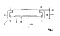
- FIG. 3 shows an end view to FIG. 2 .
- FIG. 4 is a guide rail 8 hidden.
- FIG. 5 Furthermore, a cap 18 is hidden.
- the door actuator assembly 1 comprises a door operator 4, here designed as a door closer.
- the door operator 4 has an output shaft 5.
- One end of a lever 6 is rotatably connected to this output shaft 5.
- the door operator 4 is completely embedded in the door leaf frame 3.
- the guide rail 8 is mounted in this portion of the door frame 2.
- the guide rail 8 is designed here as a slide rail and extends in a longitudinal direction 16.
- FIG. 2 shows in contrast to FIG. 1 the underside of the guide rail 8.
- the guide rail 8 is composed of a mounting surface 9 and two side walls 11. In the mounting surface 9 a plurality of mounting holes 10 are provided. About this mounting holes 10, the guide rail 8 is screwed to the door frame 2.
- the two side walls 11 are perpendicular to the mounting surface 9 and spaced from each other.
- FIG. 3 shows, the two side walls 11 each have a shoulder 12.
- a guide channel 13 is formed between the mounting surface 9, the side wall 11 and the shoulder 12.
- the guide rail 8 has two guide channels 13. In these guide channels 13, elements in the guide rail 8 along the longitudinal direction 16 can be guided linearly movable. At the same time, it is ensured by the guide channels 13 that the guided elements can not be removed from the guide rail 8 in any direction perpendicular to the longitudinal direction 16.
- a moving element 7 is guided linearly movable.
- the moving member 7 is formed as a sliding member or slider.
- a movement direction 15 of the movement element 7 corresponds to the longitudinal direction 16 of the guide rail 8.
- an eye 14 is formed in the movement element 7.
- the lever 6 is rotatable about this eye 14 connected to the moving element 7.
- FIG. 4 shows that on both sides of the moving element 7 Gleitulatel 17 are formed. These sliding wings 17 engage in the guide channels 13.
- a cap 18 is inserted in the guide rail 8.
- the cap 18 also has sliding wings 17 on both sides, which engage in the guide channels 13. Between the cap 18 and the guide rail 8, a cavity is formed.
- the stopper 19 is attached via a first screw 20 and a second screw 21.
- the first screw 20 is designed as a grub screw.
- the second screw 21 is designed as a countersunk screw.
- damping element 22 In the cavity between the cap 18 and guide rail 8, a damping element 22 is inserted.
- This damping element 22 has here two elastomer blocks 23, which consist of foamed elastomer. Between the damping element 22 and the movement element 7, a push element 24 is arranged in the guide rail 8.
- the impact element 24 is formed in one piece, but has a first portion 25 and a second portion 26. In turn, on the first section 25, track wings 17 are formed, which are guided in the guide channels 13.
- the second portion 26 has no sliding vanes 17 and thus can engage in the cavity under the cap 18.
- An area of the front of the second section 26 corresponds approximately to the surface of the end face of the damping element 22. These two end faces come to rest on each other, so that the movement of the movement element 7 is transmitted via the impact element 24 to the damping element 22.
- FIG. 3 shows a guide rail height 28 and a projection 29.
- the two sizes are measured perpendicular to the mounting surface 9.
- the projection 29 is at most 20% of the guide rail height 28.
- the damping element 22 is formed correspondingly long in the longitudinal direction 16, so that the corresponding force can also be damped.
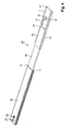
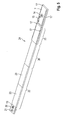
- FIGS. 6 to 9 show a second embodiment of the invention
- Mosbetuschigeran extract 1 Same or functionally identical components are provided in all embodiments with the same reference numerals.
- FIG. 8 For the sake of clarity, the guide rail 8 is hidden.
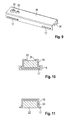
- FIG. 9 only shows the cap 18.
- the damping element 22 and correspondingly also the cap 18 does not extend so far in the longitudinal direction 16.
- the cap 18 and the damping element 22 in the direction perpendicular to the mounting surface 9 are designed to be larger.
- FIG. 7 here shows the guide rail height 28 and the projection 29.
- the projection 29 may be more than 20% of the guide rail height 28.
- an extension 30 is formed between the movement element 7 and the impact element 24, an extension 30 is formed.
- this extension 30 also includes sliding wings for guiding in the guide channels 13.
- the projection of the movement element 7, the extension 30 and a majority of the push member 24 is defined as in the first embodiment and is at most 20% of the guide rail height.
- the impact element 24 has approximately the same end face as the damping element 22. Therefore, wedge-shaped stiffeners 32 are provided on the impact element 24, which stiffen an end wall 31 of the impact element 24.
- the stop 19 has sliding wings 17 for guiding in the guide channels 13.
- FIG. 9 shows the cap 18 a shock stopper 34 formed as a tab.
- This shock element stopper 34 engages behind the wall 31 of the push element 24.
- the push element 24 is blocked in a direction of movement by the damping element 22 and abuts the push element stop 34 in the other direction of movement.
- FIG. 9 two holes 33 in the cap 18.
- the two screw 20, 21 are used, so that simultaneously with the attachment of the stopper 19 and the cap 18 is fixed relative to the stop 19.
- the elastomer blocks 23 are fixed between the wings 17 from the stop 19 and the walls left / right of the wings 17 of the cap 18.
- FIGS. 10 to 14 show various embodiments and details of the Matbetuschigeran teaspoon invention. These embodiments may be provided on both embodiments.
- FIG. 10 shows a recess 35 in the cap 18.
- This recess 35 may be formed as a slot or as a continuous slot. When compressing the damping element 22 so the damping element 22 can extend through the recess 35.
- FIG. 11 shows a closed cap 18.
- a free space 36 between the damping element 22 and the inner wall of the cap 18 is provided so that an expansion of the damping element 22 is possible.
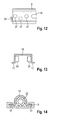
- FIG. 12 shows an embodiment of the recess as further holes 37.
- the damping element 22 can extend through the other holes 37 therethrough.
- the shock element stop 34 designed as a tab, is arranged laterally here.
- FIG. 13 shows the use of two impact element stops 34, each of which laterally engage behind the impact element 24.
- FIG. 14 shows that both the cap 18 and the damping element 22 in cross section can not be rectangular but also round.
- Fig. 15 and 16 show a detail of the formation of the stopper 19 and the cap 18 for all embodiments.
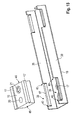
- Fig. 15 shows the stopper 19 and the cap 18 in an exploded view.
- Fig. 16 the composite state is shown.
- the cap 18 has two parallel Kappenwandungen 38.
- a wing 17 is formed by a notch.
- the notch is thus formed by the wing 17, which is in particular perpendicular to the cap wall 38, and two webs 40.
- the width of the webs 40 corresponds to the wall thickness of the cap 18, in particular the cap wall 38th
- the stop 19 has two parallel end faces 41.
- the end faces 41 are perpendicular to the longitudinal direction 16. In the assembled state according to Fig. 16 stand the end faces 41 of the webs 40 opposite.
- the wings 17 of the stopper 19 lie on the wings 17 of the cap 18.
- a positive reception of the stop 19 is provided in the cap 18, in particular to fix the stop 19 in the direction of movement 16 relative to the cap 18.
Landscapes
- Engineering & Computer Science (AREA)
- Mechanical Engineering (AREA)
- Power-Operated Mechanisms For Wings (AREA)
- Closing And Opening Devices For Wings, And Checks For Wings (AREA)
- Lock And Its Accessories (AREA)
Abstract
Description
- Vorliegende Erfindung betrifft eine Türbetätigeranordnung zum Bewegen eines Türflügels. Dabei ist insbesondere eine Dämpfung des Türflügels in der Endlage vorgesehen.
- Türbetätigeranordnungen umfassen in der Regel einen Türbetätiger, ausgebildet als Türantrieb, Türschließer oder Servotürschließer, eine Führungsschiene mit einem darein geführten Bewegungselement (auch: Gleitstück geführt in einer Gleitschiene) und einen Hebel als Verbindung zwischen dem Türbetätiger und dem Bewegungselement. Der Türbetätiger wird entweder ortsfest an der Wand oder Zarge oder direkt am Türflügel befestigt. Befindet sich der Türbetätiger beispielhaft am Türflügel, so wird die Kraft von der Abtriebswelle des Türbetätigers über den Hebel auf das Bewegungselement übertragen. Das Bewegungselement ist dabei in der Führungsschiene, die sich ortsfest an Wand oder Zarge befindet, linear beweglich geführt. Um die Bewegung des Bewegungselementes und somit auch die Bewegung des Türflügels in der Endlage zu dämpfen, ist üblicherweise ein Puffer an oder in der Führungsschiene vorgesehen. Das Bewegungselement läuft auf diesen Puffer in der Endlage auf.
- Es ist Aufgabe vorliegender Erfindung, eine Türbetätigeranordnung bereitzustellen, die bei kostengünstiger Herstellung und Montage sehr kleinbauend ist und ein effektives Dämpfen der Bewegung des Bewegungselementes und somit auch des Türflügels ermöglicht. Insbesondere soll die Führungsschiene und/oder der Türbetätiger in den Rahmen einer Tür oder in den Rahmen eines Türflügels integrierbar bzw. versenkbar sein. Des Weiteren bevorzugt ist gefordert, dass im geschlossenen Zustand des Türflügels weder die Führungsschiene noch der Türbetätiger für den Benutzer sichtbar sind.
- Die Lösung der Aufgabe erfolgt durch die Merkmale des Anspruchs 1. Die Unteransprüche haben bevorzugte Weiterbildungen der Erfindung zum Gegenstand.
- Somit wird die Aufgabe gelöst durch eine Türbetätigeranordnung zum Bewegen eines Türflügels umfassend eine sich in Längsrichtung erstreckende Führungsschiene mit zumindest einem Führungskanal. Insbesondere sind zwei gegenüber liegende Führungskanäle vorgesehen. In der Führungsschiene geführte Elemente werden durch eine formschlüssige Aufnahme im Führungskanal geführt. Dadurch sind die Elemente lediglich in Längsrichtung beweglich und können in keine der anderen Richtungen aus der Führungsschiene entnommen werden. Ferner sind ein im Führungskanal linear beweglich geführtes Bewegungselement und ein Türbetätiger mit einer Abtriebswelle vorgesehen. Der Türbetätiger ist insbesondere ein Türschließer. In bevorzugter Anordnung wird der Türbetätiger in den Rahmen eines Türflügels eingelassen. In entsprechender Weise befindet sich die Führungsschiene im Rahmen der Türe. Weiterhin umfasst die Anordnung einen Hebel, der drehfest mit der Abtriebswelle und drehbar mit dem Bewegungselement verbunden ist, und eine im Führungskanal geführte und bezüglich der Führungsschiene ortsfest fixierte Kappe. Die Kappe ist im Führungskanal linear beweglich geführt und kann somit bei der Montage an die gewünschte Position gebracht werden. An dieser Position wird die Kappe in der Führungsschiene fixiert, sodass sie nicht mehr linear beweglich ist. Als Puffer wird ein lose im Hohlraum zwischen der Kappe und der Führungsschiene aufgenommenes Dämpfungselement verwendet. Das Dämpfungselement ist einfach gestaltet und wird mittels der Kappe an einer bestimmten Position in der Führungsschiene gehalten. Zwischen dem Dämpfungselement und der Kappe ist ausreichend Platz, sodass sich das Dämpfungselement ausdehnen kann. Das Dämpfungselement besteht insbesondere aus zelligem Vulkollan. Ferner ist ein im Führungskanal linear beweglich geführtes Stoßelement zwischen dem Dämpfungselement und dem Bewegungselement vorgesehen. Über dieses Stoßelement wird in der Endlage des Türflügels die Kraft vom Bewegungselement auf das Dämpfungselement übertragen, sodass die Bewegung des Bewegungselementes gedämpft wird. Je nach Gewicht des Türflügels hat das Dämpfungselement eine gewisse Größe und Masse. Will man nun eine sehr schmale Führungsschiene bauen, um sie beispielsweise in den Rahmen des Türflügels oder der Türe zu integrieren, so muss man das Dämpfungselement relativ lang und schmal ausbilden, damit es in der Führungsschiene Platz findet. Eine einfache Vergrößerung, insbesondere Verlängerung, der Dämpfungs-oder Pufferelemente in den herkömmlichen Konstruktionen führt stets dazu, dass beim Auflaufen des Bewegungselementes auf das Dämpfungselement das Dämpfungselement ausbaucht und knickt. Infolgedessen ist erfindungsgemäß die Kappe vorgesehen. Die Kappe besteht bevorzugt aus stabilem Blech oder Kunststoff und fixiert die Lage des Dämpfungselementes. Das Stoßelement drückt nicht auf die Kappe sondern auf das Dämpfungselement und verformt somit das Dämpfungselement innerhalb der Kappe bzw. in dem Hohlraum zwischen Kappe und Führungsschiene.
- Bevorzugt ist vorgesehen, dass das Stoßelement teilweise in dem Hohlraum zwischen Kappe und Führungsschiene eingreift. Das Dämpfungselement befindet sich somit vollständig in dem Hohlraum und steht nicht über die Kappe hervor. Dadurch wir sichergestellt, dass das Dämpfungselement lediglich im Hohlraum verformt wird.
- Des Weiteren ist vorteilhafterweise vorgesehen, dass das Dämpfungselement nicht in den Führungskanal eingreift. Das Dämpfungselement ist also nicht im Führungskanal beweglich geführt, sondern ist einfach, beispielsweise als Block gestaltet und liegt lose in dem Hohlraum. In der Regel ist das Material des Dämpfungselementes nicht hart genug, um daran feine Strukturen auszubilden, die im Führungskanal geführt werden können.
- In weiterer bevorzugter Ausführung ist ein ortsfest bezüglich der Führungsschiene fixierter Anschlag vorgesehen. Der Anschlag befindet sich auf der dem Stoßelement abgewandten Seite des Dämpfungselementes. Das Dämpfungselement liegt an diesem Anschlag an, sodass die Position des Dämpfungselementes innerhalb der Führungsschiene durch den Anschlag definiert ist. In besonders bevorzugter Ausführung ist eine Schraube oder ein Bolzen zum Befestigen des Anschlags vorgesehen, wobei die Schraube und/oder der Bolzen durch den Anschlag und durch die Führungsschiene hindurch in den darunter liegenden Türflügel, in die Zarge oder in die Wand reichen. Der Anschlag ist somit nicht nur mit der Führungsschiene sondern auch direkt mit der darunter liegenden Konstruktion verbunden. Dadurch können sehr schwere Türflügel durch die erfindungsgemäße Anordnung gedämpft werden. Zusätzlich zu der oben genannten Schraube oder dem Bolzen ist eine weitere Verschraubung vorgesehen, mit der der Anschlag in der Führungsschiene fixiert werden kann. Hierzu eignet sich beispielsweise eine Madenschraube, die den Anschlag in der Führungsschiene klemmt. Diese weitere Verschraubung ist insbesondere sinnvoll, wenn der Monteur zunächst die gewünschte Position des Anschlags innerhalb der Führungsschiene vorjustieren will und erst in einem letzten Schritt die Führungsschiene durchbohrt um die Schraube oder den Bolzen einzusetzen.
- In vorteilhafter Ausgestaltung ist die Kappe direkt mit dem Anschlag verbunden bzw. verschraubt. Beispielsweise befindet sich der Anschlag in dem Hohlraum zwischen Kappe und Führungsschiene. Die oben genannten Verschraubungsmöglichkeiten werden dann durch die Kappe und gegebenenfalls durch den Anschlag und durch die Führungsschiene durchgesetzt.
- Ferner ist bevorzugt vorgesehen, dass das Dämpfungselement direkt am Anschlag anliegt und/oder das Stoßelement direkt am Dämpfungselement anliegt. Bevorzugt befindet sich also zwischen dem Dämpfungselement und dem Anschlag kein weiteres Bauteil. Auch das Stoßelement sollte direkt mit dem Dämpfungselement in Berührung kommen, sodass die Kraft direkt in das Dämpfungselement eingeleitet wird.
- In vorteilhafter Ausführung ist vorgesehen, dass das Stoßelement in zumindest zwei Abschnitte unterteilt ist, wobei der erste Abschnitt dem Bewegungselement zugewandt ist und im Führungskanal geführt ist, und wobei der zweite Abschnitt nicht in den Führungskanal eingreift und in den Hohlraum zwischen Kappe und Führungsschiene eingreift. Die beiden Abschnitte des Stoßelementes sind insbesondere integral miteinander gefertigt, sodass das Stoßelement einstückig ist. Über den ersten Abschnitt ist das Stoßelement in den Führungskanälen geführt und somit linear beweglich. Der zweite Abschnitt muss etwas schmaler ausgeführt werden, damit er in den Hohlraum zwischen Kappe und Führungsschiene eingreifen kann und nicht mit der Kappe im Führungskanal kollidiert. Deshalb wird der zweite Abschnitt des Stoßelementes nicht im Führungskanal geführt.
- Bevorzugt ist vorgesehen, dass das Stoßelement bezüglich der Kappe oder bezüglich des Dämpfungselementes nur minimal beweglich ist. Bei einer normalen Bewegung des Türflügels wird also nur das Bewegungselement jedoch nicht das Stoßelement mit bewegt. In der Endlage läuft dann das Bewegungselement auf das Stoßelement auf. Insbesondere ist vorgesehen, dass an der Kappe zumindest ein Stoßelementanschlag ausgebildet ist. Dieser Stoßelementanschlag ist insbesondere als eine oder mehrere gebogene bzw. abgewindelte Laschen ausgebildet. Der Stoßelementanschlag verhindert ein vollständiges Herausbewegen des Stoßelementes aus dem Hohlraum zwischen Kappe und Führungsschiene. Dadurch ist die Führungsschiene bezüglich der Kappe im begrenzten Umfang linear beweglich. An einer Seite stößt das Stoßelement gegen den Stoßelementanschlag. Auf der anderen Seite stößt das Stoßelement gegen das Dämpfungselement.
- Bevorzugt weist die Führungsschiene eine Montagefläche auf. Die Montagefläche ist diejenige Fläche, die am Türflügel, der Zarge oder der Wand zum Anliegen kommt. Insbesondere sind in der Montagefläche Montagelöcher vorgesehen. Über diese Montagelöcher wird die Führungsschiene befestigt. Eine Führungsschienenhöhe ist senkrecht zu der Montagefläche definiert. Die Kappe kann in Richtung senkrecht zur Montagefläche etwas über die Führungsschiene überstehen. Um einen schmalen Aufbau der Anordnung in Richtung senkrecht zur Montagefläche zu gewährleisten, wird definiert, dass das Dämpfungselement soweit in die Länge gezogen wird, sodass die Kappe in Richtung senkrecht zur Montagefläche um höchstens 20%, vorzugsweise höchstens 10%, der Führungsschienenhöhe über die Führungsschiene übersteht.
- In einer alternativen Ausführung ist vorgesehen, dass die Kappe in Richtung senkrecht zur Montagefläche um mehr als 20%, vorzugsweise mehr als 40%, der Führungsschienenhöhe die Führungsschiene überragt. Dabei ist jedoch das Bewegungselement in Richtung senkrecht zur Montagefläche sehr schmal ausgebildet und es wird definiert, dass das Bewegungselement in Richtung senkrecht zur Montagefläche um höchstens 20%, vorzugsweise höchstens 10%, der Führungsschienenhöhe die Führungsschiene überragt. Bei dieser zweiten Alternative ist besonders bevorzugt eine Verlängerung zwischen dem Bewegungselement und der Kappe angeordnet. Insbesondere wird das Bewegungselement selbst verlängert oder es wird das Stoßelement verlängert. Alternative kann auch zwischen dem Stoßelement und dem Bewegungselement die Verlängerung eingesetzt werden. Entscheidend ist, dass die Verlängerung so lange ist, dass im geschlossenen Zustand des Türflügels die Abtriebswelle des Türbetätigers zwischen dem Bewegungselement und der Kappe angeordnet ist. Es wird also die Kappe mit dem Dämpfungselement so weit nach außen in Richtung Drehachse des Türflügels verlegt, sodass im geschlossenen Zustand der Hebel, der die Abtriebswelle des Türschließers mit dem Bewegungselement verbindet, parallel zur Führungsschiene Platz findet. Ohne diese Verlängerung und bei zu großer Ausbildung der Kappe würde der Hebel an der Kappe anstoßen.
- In bevorzugter Ausführung ist vorgesehen, dass die Verlängerung form-und/oder kraftschlüssig mit dem Bewegungselement lösbar verbunden ist, und/oder dass die Verlängerung form- und/oder kraftschlüssig mit dem Stoßelement lösbar verbunden ist. Die Verlängerung kann also auf einer Seite mit dem Bewegungselement montiert und demontiert werden. Auf der anderen Seite kann die Verlängerung mit dem Stoßelement montiert und demontiert werden. Alternativ dazu ist es möglich, dass die Verlängerung mit dem Bewegungselement und/oder dem Stoßelement einstückig ausgebildet ist.
- Vorteilhafterweise ist die Länge der Verlängerung einstellbar. Dies ist beispielsweise durch eine mehrteilige Verlängerung realisierbar, die über Lochschienen, Langlöcher oder Klemmleisten in ihrer Länge einstellbar ist. Alternativ ist auch ein mechanisch kürzbares (z.B. durch Absägen) Teil, vorzugsweise aus Kunststoff, als Verlängerung möglich.
- Das Dämpfungselement umfasst zumindest einen Elastomerblock. Der Elastomerblock ist bevorzugt als geschäumter Elastomerblock, insbesondere aus zelligem Vulkollan, ausgebildet. Besonders bevorzugt ist das Dämpfungselement lediglich durch diese Elastomerblöcke gebildet. Es bedarf keiner Umhüllung oder weiteren Verarbeitung der Elastomerblöcke, da die Elastomerblöcke sicher in dem Hohlraum zwischen Kappe und Führungsschiene aufgenommen sind.
- Nachfolgend werden Ausführungsbeispiele der Erfindung anhand der begleitenden Zeichnungen im Detail erläutert. Dabei zeigen:
- Figur 1
- eine erfindungsgemäße Türbetätigeranordnung gemäß einem ersten Ausführungsbeispiel mit Türrahmen und Türflügelrahmen,
- Figur 2
- die erfindungsgemäße Türbetätigeranordnung gemäß dem ersten Ausführungsbeispiel,
- Figur 3
- eine stirnseitige Ansicht der erfindungsgemäßen Türbetätigeranordnung gemäß dem ersten Ausführungsbeispiel,
- Figur 4
- ein erstes Detail der erfindungsgemäßen Türbetätigeranordnung gemäß dem ersten Ausführungsbeispiel,
- Figur 5
- ein zweites Detail der erfindungsgemäßen Türbetätigeranordnung gemäß dem ersten Ausführungsbeispiel,
- Figur 6
- eine erfindungsgemäße Türbetätigeranordnung gemäß einem zweiten Ausführungsbeispiel,
- Figur 7
- eine Seitenansicht der erfindungsgemäßen Türbetätigeranordnung gemäß dem zweiten Ausführungsbeispiel,
- Figur 8
- ein Detail der erfindungsgemäßen Türbetätigeranordnung gemäß dem zweiten Ausführungsbeispiel,
- Figur 9
- eine Kappe der erfindungsgemäßen Türbetätigeranordnung gemäß dem zweiten Ausführungsbeispiel,
- Figuren 10 bis 14
- verschiedene Varianten für die erfindungsgemäße Türbetätigeranordnung gemäß beiden Ausführungsbeispielen,
- Fig. 15
- eine Kappe und einen Anschlag in Explosionsdarstellung gemäß der erfindungsgemäßen Türbetätigeranordnung für alle Ausführungsbeispiele, und
- Fig. 16
- eine zusammengesetzte Darstellung zu
Fig. 15 . - Im Folgenden wird anhand der
Figuren 1 bis 5 die Türbetätigeranordnung 1 gemäß dem ersten Ausführungsbeispiel beschrieben. -
Figur 1 zeigt die Türbetätigeranordnung 1 integriert in einen Türrahmen 2 und einen Türflügelrahmen 3. InFigur 2 sind der Türrahmen 2 und der Türflügelrahmen 3 ausgeblendet.Figur 3 zeigt eine stirnseitige Ansicht zurFigur 2 . InFigur 4 ist eine Führungsschiene 8 ausgeblendet. InFigur 5 ist des Weiteren eine Kappe 18 ausgeblendet. - Gemäß den
Figuren 1 bis 5 umfasst die Türbetätigeranordnung 1 einen Türbetätiger 4, hier ausgebildet als Türschließer. Der Türbetätiger 4 weist eine Abtriebswelle 5 auf. Ein Ende eines Hebels 6 ist drehfest mit dieser Abtriebswelle 5 verbunden. Der Türbetätiger 4 ist vollständig in den Türflügelrahmen 3 eingelassen. InFigur 1 ist der obere, horizontale Anteil des Türrahmens 2 nicht dargestellt. In diesem Anteil des Türrahmens 2 ist die Führungsschiene 8 montiert. Die Führungsschiene 8 ist hier ausgebildet als Gleitschiene und erstreckt sich in einer Längsrichtung 16. -
Figur 2 zeigt im Gegensatz zuFigur 1 die Unterseite der Führungsschiene 8. Die Führungsschiene 8 setzt sich zusammen aus einer Montagefläche 9 und zwei Seitenwänden 11. In der Montagefläche 9 sind mehrere Montagelöcher 10 vorgesehen. Über diese Montagelöcher 10 wird die Führungsschiene 8 mit dem Türrahmen 2 verschraubt. Die beiden Seitenwände 11 stehen senkrecht zur Montagefläche 9 und beabstandet von einander. Wie insbesondereFigur 3 zeigt, weisen die beiden Seitenwände 11 jeweils einen Absatz 12 auf. Dadurch entsteht zwischen der Montagefläche 9, der Seitenwand 11 und dem Absatz 12 ein Führungskanal 13. Die Führungsschiene 8 weist zwei Führungskanäle 13 auf. In diesen Führungskanälen 13 können Elemente in der Führungsschiene 8 entlang der Längsrichtung 16 linear beweglich geführt werden. Gleichzeitig wird durch die Führungskanäle 13 sichergestellt, dass die geführten Elemente in keiner Richtung senkrecht zur Längsrichtung 16 aus der Führungsschiene 8 entnommen werden können. - In der Führungsschiene 8 ist ein Bewegungselement 7 linear beweglich geführt. Das Bewegungselement 7 ist als Gleitelement oder Gleitstück ausgebildet. Eine Bewegungsrichtung 15 des Bewegungselementes 7 entspricht der Längsrichtung 16 der Führungsschiene 8. In dem Bewegungselement 7 ist ein Auge 14 ausgebildet. Der Hebel 6 ist über dieses Auge 14 drehbeweglich mit dem Bewegungselement 7 verbunden. Insbesondere
Figur 4 zeigt, dass beidseitig am Bewegungselement 7 Gleitflügel 17 ausgebildet sind. Diese Gleitflügel 17 greifen in die Führungskanäle 13 ein. - Des Weiteren ist in der Führungsschiene 8 eine Kappe 18 eingesetzt. Auch die Kappe 18 weist beidseitig Gleitflügel 17 auf, die in die Führungskanäle 13 eingreifen. Zwischen der Kappe 18 und der Führungsschiene 8 ist ein Hohlraum ausgebildet.
- An einem Ende der Kappe 18 befindet sich zwischen der Kappe 18 und der Führungsschiene 8 ein Anschlag 19. Der Anschlag 19 ist über eine erste Schraube 20 und über eine zweite Schraube 21 befestigt. Die erste Schraube 20 ist als Madenschraube ausgeführt. Die zweite Schraube 21 ist als Senkschraube ausgeführt. Mittels der ersten Schraube 20 wird die Position des Anschlags 19 in der Führungsschiene 8 fixiert. Die zweite Schraube 21 geht durch die Führungsschiene 8 hindurch, wie dies beispielsweise
Figur 3 zeigt. Dadurch kann der Anschlag 19 über die zweite Schraube 21 fest mit der unter der Führungsschiene 8 liegenden Konstruktion verbunden werden. - In den Hohlraum zwischen Kappe 18 und Führungsschiene 8 ist ein Dämpfungselement 22 eingesetzt. Dieses Dämpfungselement 22 weist hier zwei Elastomerblöcke 23 auf, die aus geschäumtem Elastomer bestehen. Zwischen dem Dämpfungselement 22 und dem Bewegungselement 7 ist ein Stoßelement 24 in der Führungsschiene 8 angeordnet. Das Stoßelement 24 ist einteilig ausgebildet, weist jedoch einen ersten Abschnitt 25 und einen zweiten Abschnitt 26 auf. Am ersten Abschnitt 25 sind wiederum Gleüflügel 17 ausgebildet, die in den Führungskanälen 13 geführt sind. Der zweite Abschnitt 26 weist keine Gleitflügel 17 auf und kann somit in den Hohlraum unter der Kappe 18 eingreifen. Eine Fläche der Stirnseite des zweiten Abschnitts 26 entspricht in etwa der Fläche der Stirnseite des Dämpfungselementes 22. Diese beiden Stirnseiten kommen auf einander zum Anliegen, sodass die Bewegung des Bewegungselementes 7 über das Stoßelement 24 auf das Dämpfungselement 22 übertragen wird.
-
Figur 3 zeigt eine Führungsschienenhöhe 28 und einen Überstand 29. Die beiden Größen werden senkrecht zur Montagefläche 9 gemessen. Um einen sehr schmalen Aufbau senkrecht zur Montagefläche 9 zu gewährleisten, wird definiert, dass der Überstand 29 höchstens 20% der Führungsschienenhöhe 28 beträgt. Das Dämpfungselement 22 wird in Längsrichtung 16 dementsprechend lang ausgebildet, sodass die entsprechende Kraft auch gedämpft werden kann. - Die
Figuren 6 bis 9 zeigen ein zweites Ausführungsbeispiel der erfindungsgemäßen Türbetätigeranordnung 1. Gleiche bzw. funktional gleiche Bauteile sind in allen Ausführungsbeispielen mit den selben Bezugszeichen versehen. InFigur 8 ist der Übersichtlichkeit halber die Führungsschiene 8 ausgeblendet.Figur 9 zeigt lediglich die Kappe 18. - Im zweiten Ausführungsbeispiel erstreckt sich, im Gegensatz zum ersten Ausführungsbeispiel, das Dämpfungselement 22 und in entsprechender Weise auch die Kappe 18 nicht so weit in Längsrichtung 16. Um jedoch auch hier eine entsprechend große Kraft abzudämpfen, müssen die Kappe 18 und das Dämpfungselement 22 in Richtung senkrecht zur Montagefläche 9 größerbauend ausgebildet werden.
Figur 7 zeigt hier die Führungsschienenhöhe 28 und den Überstand 29. Der Überstand 29 kann mehr als 20% der Führungsschienenhöhe 28 betragen. Zwischen dem Bewegungselement 7 und dem Stoßelement 24 ist eine Verlängerung 30 ausgebildet. Vorzugsweise umfasst auch diese Verlängerung 30 Gleitflügel zur Führung in den Führungskanälen 13. Der Überstand des Bewegungselementes 7, der Verlängerung 30 und eines Großteils des Stoßelementes 24 ist wie im ersten Ausführungsbeispiel definiert und beträgt höchstens 20 % der Führungsschienenhöhe. Durch die Verlängerung 30 wird sichergestellt, dass im geschlossenen Zustand die Abtriebswelle 5 des Türbetätigers 4 zwischen der Kappe 18 und dem Auge 14 Platz findet. Es wird somit vermieden, dass der Hebel 6 an der Kappe 18 anstößt. - Auch im zweiten Ausführungsbeispiel ist vorgesehen, dass das Stoßelement 24 in etwa die gleiche Stirnfläche aufweist wie das Dämpfungselement 22. Deswegen sind am Stoßelement 24 keilförmige Versteifungen 32 vorgesehen, die eine stirnseitige Wand 31 des Stoßelementes 24 versteifen.
- Des Weiteren weist im zweiten Ausführungsbeispiel der Anschlag 19 Gleitflügel 17 zur Führung in den Führungskanälen 13 auf.
- Wie insbesondere
Figur 9 zeigt umfasst die Kappe 18 einen Stoßelementanschlag 34 ausgebildet als Lasche. Dieser Stoßelementanschlag 34 hintergreift die Wand 31 des Stoßelementes 24. Dadurch ist das Stoßelement 24 in einer Bewegungsrichtung durch das Dämpfungselement 22 blockiert und stößt in der anderen Bewegungsrichtung am Stoßelementanschlag 34 an. Darüber hinaus zeigtFigur 9 zwei Löcher 33 in der Kappe 18. Über diese beiden Löcher 33 werden die beiden Verschraubungen 20, 21 eingesetzt, sodass gleichzeitig mit dem Befestigen des Anschlags 19 auch die Kappe 18 gegenüber dem Anschlag 19 fixiert wird. Ferner sind die Elastomerblöcke 23 zwischen den Flügeln 17 vom Anschlag 19 und den Wänden links/rechts der Flügel 17 der Kappe 18 fixiert. - Die
Figuren 10 bis 14 zeigen verschiedene Ausbildungen und Details der erfindungsgemäßen Türbetätigeranordnung. Diese Ausbildungen können an beiden Ausführungsbeispielen vorgesehen werden. -
Figur 10 zeigt eine Ausnehmung 35 in der Kappe 18. Diese Ausnehmung 35 kann als Langloch oder als durchgehender Schlitz ausgebildet werden. Beim Zusammenpressen des Dämpfungselementes 22 kann sich so das Dämpfungselement 22 durch die Ausnehmung 35 ausdehnen. -
Figur 11 zeigt eine geschlossene Kappe 18. Hier ist ein Freiraum 36 zwischen dem Dämpfungselement 22 und der Innenwandung der Kappe 18 vorgesehen, sodass ein Ausdehnen des Dämpfungselementes 22 möglich ist. -
Figur 12 zeigt eine Ausbildung der Ausnehmung als weitere Löcher 37. Hier kann sich das Dämpfungselement 22 durch die weiteren Löcher 37 hindurch ausdehnen. Der Stoßelementanschlag 34, ausgebildet als Lasche, ist hier seitlich angeordnet. -
Figur 13 zeigt die Verwendung von zwei Stoßelementanschlägen 34, die jeweils seitlich das Stoßelement 24 hintergreifen. -
Figur 14 zeigt, dass sowohl die Kappe 18 als auch das Dämpfungselement 22 im Querschnitt nicht rechteckig sondern auch rund ausgebildet werden können. -
Fig. 15 und16 zeigen ein Detail der Ausbildung des Anschlags 19 und der Kappe 18 für alle Ausführungsbeispiele.Fig. 15 zeigt den Anschlag 19 und die Kappe 18 in einer Explosionsdarstellung. InFig. 16 ist der zusammengesetzte Zustand gezeigt. - Die Kappe 18 weist zwei parallele Kappenwandungen 38 auf. In jeder Kappenwandung 38 ist ein Flügel 17 durch eine Ausklinkung gebildet. Die Ausklinkung wird somit gebildet durch den Flügel 17, der insbesondere senkrecht zur Kappenwandung 38 steht, und zwei Stegen 40. Die Breite der Stege 40 entspricht der Wandstärke der Kappe 18, insbesondere der Kappenwandung 38.
- Der Anschlag 19 weist zwei parallele Stirnseiten 41 auf. Die Stirnseiten 41 stehen senkrecht zur Längsrichtung 16. Im zusammengesetzten Zustand gemäß
Fig. 16 stehen die Stirnseiten 41 den Stegen 40 gegenüber. Dadurch ist der Anschlag 19, unabhängig von der ersten und zweiten Schraube 20, 21, in Längsrichtung 16 gegenüber der Kappe 18 fixiert. Die Flügel 17 des Anschlags 19 liegen dabei auf den Flügeln 17 der Kappe 18 auf. - Bevorzugt ist also eine formschlüssige Aufnahme des Anschlags 19 in der Kappe 18 vorgesehen, um insbesondere den Anschlag 19 in Bewegungsrichtung 16 gegenüber der Kappe 18 festzusetzen.
- Der in den
Fig. 15 und16 gezeigte Formschluss zwischen Anschlag 19 und Kappe 18 ist insbesondere für die Montage der Türbetätigeranordnung 1 von Vorteil. Bevor der Anschlag 19 mittels der Schrauben 20, 21 fest mit der Türzarge und/oder der Führungsschiene 8 verbunden wird, wird der Anschlag 19 mittels der Ausklinkung gegenüber der Kappe 18 fixiert.Bezugszeichenliste 1 Türbetätigeranordnung 2 Türrahmen 3 Türflügelrahmen 4 Türbetätiger 5 Abtriebswelle 6 Hebel 7 Bewegungselement 8 Führungsschiene 9 Montagefläche 10 Montagelöcher 11 Seitenwände 12 Absätze 13 Führungskanäle 14 Auge 15 Bewegungsrichtung 16 Längsrichtung 17 Flügel 18 Kappe 19 Anschlag 20 Erste Schraube 21 Zweite Schraube 22 Dämpfungselement 23 Elastomerblock 24 Stoßelement 25 Erster Abschnitt 26 Zweiter Abschnitt 27 --- 28 Führungsschienenhöhe 29 Überstand 30 Verlängerung 31 Wand 32 Keilförmige Versteifung 33 Löcher 34 Stoßelementanschlag, Lasche 35 Langloch oder durchgehender Schlitz 36 Freiraum 37 Weitere Löcher 38 Kappenwandungen 39 Ausklinkungen 40 Stege 41 Stirnseiten
Claims (15)
- Türbetätigeranordnung (1) zum Bewegen eines Türflügels umfassend:- eine sich in Längsrichtung (16) erstreckende Führungsschiene (8) mit zumindest einem Führungskanal (13), wobei in der Führungsschiene (8) geführte Elemente durch eine formschlüssige Aufnahme im Führungskanal (8) lediglich in Längsrichtung (16) beweglich sind,- ein im Führungskanal (13) linear beweglich geführtes Bewegungselement (7),- einen Türbetätiger (4) mit einer Abtriebswelle (5),- einen Hebel (6), der drehfest mit der Abtriebswelle (5) und drehbar mit dem Bewegungselement (7) verbunden ist,- eine im Führungskanal (13) geführte und bezüglich der Führungsschiene (8) ortsfest fixierte Kappe (18),- ein lose im Hohlraum zwischen der Kappe (18) und der Führungsschiene (8) aufgenommenes Dämpfungselement (22),- ein im Führungskanal (13) linear beweglich geführtes Stoßelement (24) zwischen dem Dämpfungselement (22) und dem Bewegungselement (7).
- Türbetätigeranordnung nach Anspruch 1, dadurch gekennzeichnet, dass das Stoßelement (24) teilweise in den Hohlraum zwischen Kappe (18) und Führungsschiene (8) eingreift.
- Türbetätigeranordnung nach einem der vorhergehenden Ansprüche, dadurch gekennzeichnet, dass das Dämpfungselement (22) nicht in den Führungskanal (13) eingreift.
- Türbetätigeranordnung nach einem der vorhergehenden Ansprüche, gekennzeichnet durch einen ortsfest bezüglich der Führungsschiene (8) fixierten Anschlag (19) auf der dem Stoßelement (24) abgewandten Seite des Dämpfungselementes (22).
- Türbetätigeranordnung nach Anspruch (4), gekennzeichnet durch zumindest eine Schraube (21) und/oder einen Bolzen zum Befestigen des Anschlags (19), wobei die Schraube (21) und/oder der Bolzen durch den Anschlag (19) und die Führungsschiene (8) hindurch in den Türflügel, die Zarge oder die Wand reicht.
- Türbetätigeranordnung nach einem der Ansprüche (4) oder (5), dadurch gekennzeichnet, dass die Kappe (18) mit dem Anschlag (19) verbunden, vorzugsweise verschraubt, ist.
- Türbetätigeranordnung nach einem der vorhergehenden Ansprüche, dadurch gekennzeichnet, dass das Dämpfungselement (22) direkt am Anschlag (19) anliegt und/oder das Stoßelement (24) direkt am Dämpfungselement (22) anliegt.
- Türbetätigeranordnung nach einem der vorhergehenden Ansprüche, dadurch gekennzeichnet, dass das Stoßelement (24) in zumindest zwei Abschnitte unterteilt ist, wobei der erste Abschnitt (25) dem Bewegungselement (7) zugewandt ist und im Führungskanal (13) geführt ist, und wobei der zweite Abschnitt (26) nicht in den Führungskanal (13) eingreift und in den Hohlraum zwischen Kappe (18) und Führungsschiene (8) eingreift.
- Türbetätigeranordnung nach einem der vorhergehenden Ansprüche, dadurch gekennzeichnet, dass an der Kappe (18) zumindest ein Stoßelementanschlag (34), vorzugsweise zumindest eine gebogene Lasche, ausgebildet ist, wobei der Stoßelementanschlag (34) ein vollständiges Herausbewegen des Stoßelementes (24) aus dem Hohlraum zwischen Kappe (18) und Führungsschiene (8) verhindert.
- Türbetätigeranordnung nach einem der vorhergehenden Ansprüche, dadurch gekennzeichnet, dass die Führungsschiene (8) eine Montagefläche (9) aufweist, wobei die Montagefläche (9) am Türflügel, der Zarge oder der Wand zum Anliegen kommt, wobei eine Führungsschienenhöhe (28) senkrecht zur Montagefläche (9) definiert ist, und wobei die Kappe (18) in Richtung senkrecht zur Montagefläche (9) um höchstens 20%, vorzugsweise höchstens 10%, der Führungsschienenhöhe (28) die Führungsschiene (8) überragt.
- Türbetätigeranordnung nach einem der Ansprüche 1 bis 9, dadurch gekennzeichnet, dass die Führungsschiene (8) eine Montagefläche (9) aufweist, wobei die Montagefläche (9) am Türflügel, der Zarge oder der Wand zum Anliegen kommt, wobei eine Führungsschienenhöhe (28) senkrecht zur Montagefläche (9) definiert ist, wobei die Kappe (18) in Richtung senkrecht zur Montagefläche (9) um mehr als 20%, vorzugsweise mehr als 40%, der Führungsschienenhöhe (28) die Führungsschiene (8) überragt, und wobei das Bewegungselement (7) in Richtung senkrecht zur Montagefläche (9) um höchstens 20%, vorzugsweise höchsten 10%, der Führungsschienenhöhe (28) die Führungsschiene (8) überragt.
- Türbetätigeranordnung nach einem der vorhergehenden Ansprüche, gekennzeichnet durch eine Verlängerung (30) zwischen dem Bewegungselement (7) und der Kappe (18), wobei die Verlängerung (30) so lang ist, dass im geschlossenen Zustand des Türflügels die Abtriebswelle (5) des Türbetätigers (4) zwischen dem Bewegungselement (7) und der Kappe (18) angeordnet ist.
- Türbetätigeranordnung nach Anspruch (12), dadurch gekennzeichnet, dass die Verlängerung (30) form- und/oder kraftschlüssig mit dem Bewegungselement (7) lösbar verbunden ist, oder dass die Verlängerung (30) form- und/oder kraftschlüssig mit dem Stoßelement (24) lösbar verbunden ist.
- Türbetätigeranordnung nach einem der Ansprüche 12 oder 13, dadurch gekennzeichnet, dass die Länge der Verlängerung (30) einstellbar oder mechanisch kürzbar ist.
- Türbetätigeranordnung nach einem der vorhergehenden Ansprüche, dadurch gekennzeichnet, dass das Dämpfungselement (22) zumindest einen Elastomerblock (23), vorzugsweise zumindest einen geschäumten Elastomerblock, umfasst.
Applications Claiming Priority (1)
| Application Number | Priority Date | Filing Date | Title |
|---|---|---|---|
| DE102012105111A DE102012105111A1 (de) | 2012-06-13 | 2012-06-13 | Türbetätigeranordnung |
Publications (3)
| Publication Number | Publication Date |
|---|---|
| EP2674558A2 true EP2674558A2 (de) | 2013-12-18 |
| EP2674558A3 EP2674558A3 (de) | 2016-08-24 |
| EP2674558B1 EP2674558B1 (de) | 2018-04-11 |
Family
ID=48444037
Family Applications (1)
| Application Number | Title | Priority Date | Filing Date |
|---|---|---|---|
| EP13002573.7A Active EP2674558B1 (de) | 2012-06-13 | 2013-05-16 | Türbetätigeranordnung |
Country Status (2)
| Country | Link |
|---|---|
| EP (1) | EP2674558B1 (de) |
| DE (1) | DE102012105111A1 (de) |
Cited By (1)
| Publication number | Priority date | Publication date | Assignee | Title |
|---|---|---|---|---|
| WO2021009107A1 (de) * | 2019-07-12 | 2021-01-21 | Maco Technologie Gmbh | Führungsschienenbaugruppe für einen öffnungsbegrenzer, öffnungsbegrenzer mit solch einer führungsschienenbaugruppe sowie flügelanordnung mit solch einem öffnungsbegrenzer |
Family Cites Families (3)
| Publication number | Priority date | Publication date | Assignee | Title |
|---|---|---|---|---|
| DE2436299C2 (de) * | 1974-07-27 | 1989-04-06 | Wilh. Frank Gmbh, 7022 Leinfelden-Echterdingen | Vorrichtung zur Begrenzung des Öffnungswinkels eines Flügels eines Fensters, einer Tür o.dgl |
| DE3927817C5 (de) * | 1989-08-23 | 2009-09-10 | Geze Gmbh | Vorrichtung zur Öffnungsbegrenzung für eine Schwenktür |
| DE102008048992B4 (de) * | 2008-09-25 | 2013-05-16 | Geze Gmbh | Feststellvorrichtung für einen Flügel einer Tür |
-
2012
- 2012-06-13 DE DE102012105111A patent/DE102012105111A1/de not_active Withdrawn
-
2013
- 2013-05-16 EP EP13002573.7A patent/EP2674558B1/de active Active
Non-Patent Citations (1)
| Title |
|---|
| None |
Cited By (1)
| Publication number | Priority date | Publication date | Assignee | Title |
|---|---|---|---|---|
| WO2021009107A1 (de) * | 2019-07-12 | 2021-01-21 | Maco Technologie Gmbh | Führungsschienenbaugruppe für einen öffnungsbegrenzer, öffnungsbegrenzer mit solch einer führungsschienenbaugruppe sowie flügelanordnung mit solch einem öffnungsbegrenzer |
Also Published As
| Publication number | Publication date |
|---|---|
| EP2674558A3 (de) | 2016-08-24 |
| EP2674558B1 (de) | 2018-04-11 |
| DE102012105111A1 (de) | 2013-12-19 |
Similar Documents
| Publication | Publication Date | Title |
|---|---|---|
| EP2474698B1 (de) | Dichtungsvorrichtung mit einem Dichtungsprofil und einem Mechanismus zum Verschieben des Dichtungsprofils bei Betätigung des Mechanismus | |
| EP2746503A2 (de) | Kraftfahrzeugschloss | |
| EP2376732B1 (de) | Schiebetürbeschlag für zweiflügelige schiebetür | |
| DE202012001762U1 (de) | Kettenantrieb für einen Stellantrieb zum automatischen Öffnen und Schließen einer Lüftungsvorrichtung | |
| EP2992156B1 (de) | Führungsanordnung einer schiebetür, schiebetür und möbel | |
| EP2754805B1 (de) | Riegelstange für einen Riegelstangenbeschlag | |
| EP1557516B1 (de) | Laufwerk für eine Schiebe- oder Faltschiebetür | |
| EP2405095B1 (de) | Türdichtung mit Befestigungselement | |
| EP2058463B1 (de) | Eckumlenkung für ein Treibstangenbeschlagsystem für einen Fenster- oder Türflügel | |
| EP2792830A2 (de) | Halteelement zur Halterung eines Beschlagteils | |
| EP2674558B1 (de) | Türbetätigeranordnung | |
| AT512327B1 (de) | Hebe/schiebetür | |
| EP3763911B1 (de) | Führungsschienenvorrichtung für ein rolltor oder ein rollgitter | |
| EP3655610B1 (de) | Absenkdichtung | |
| DE102018132206B3 (de) | Scharniersystem, Fahrzeugaufbau, Fahrzeug und Verfahren zur Montage einer Türe | |
| DE202016106504U1 (de) | Montagewerkzeug für die Montage einer Schaltschranktür an einem Schaltschrankgehäuse und eine entsprechende Schaltschrankanordnung | |
| EP2672046A2 (de) | Führungsschienenanordnung | |
| EP3477029A1 (de) | Führungsbeschlag für einen schiebeflügel | |
| EP2759666A2 (de) | Profilelement | |
| EP2538007A2 (de) | System mit einem Profil und einem Beschlagteil | |
| DE102008057397A1 (de) | Linearführung | |
| EP3121356B1 (de) | Anordnung eines scharniers an einem hohlkammerprofil | |
| DE202015106724U1 (de) | Beschlaganordnung für einen Schiebeflügel | |
| AT517263A1 (de) | Schließvorrichtung für eine Schiebetür | |
| DE102013226720B4 (de) | Einstellbare Vertikalaussteifung mit Gleiter für einen abstellbaren Flügel eines Fensters einer Tür oder dergleichen |
Legal Events
| Date | Code | Title | Description |
|---|---|---|---|
| PUAI | Public reference made under article 153(3) epc to a published international application that has entered the european phase |
Free format text: ORIGINAL CODE: 0009012 |
|
| AK | Designated contracting states |
Kind code of ref document: A2 Designated state(s): AL AT BE BG CH CY CZ DE DK EE ES FI FR GB GR HR HU IE IS IT LI LT LU LV MC MK MT NL NO PL PT RO RS SE SI SK SM TR |
|
| AX | Request for extension of the european patent |
Extension state: BA ME |
|
| RAP1 | Party data changed (applicant data changed or rights of an application transferred) |
Owner name: DORMA DEUTSCHLAND GMBH |
|
| PUAL | Search report despatched |
Free format text: ORIGINAL CODE: 0009013 |
|
| AK | Designated contracting states |
Kind code of ref document: A3 Designated state(s): AL AT BE BG CH CY CZ DE DK EE ES FI FR GB GR HR HU IE IS IT LI LT LU LV MC MK MT NL NO PL PT RO RS SE SI SK SM TR |
|
| AX | Request for extension of the european patent |
Extension state: BA ME |
|
| RIC1 | Information provided on ipc code assigned before grant |
Ipc: E05F 3/22 20060101AFI20160720BHEP Ipc: E05F 5/02 20060101ALI20160720BHEP Ipc: E05F 5/00 20060101ALI20160720BHEP Ipc: E05C 17/24 20060101ALI20160720BHEP |
|
| STAA | Information on the status of an ep patent application or granted ep patent |
Free format text: STATUS: REQUEST FOR EXAMINATION WAS MADE |
|
| 17P | Request for examination filed |
Effective date: 20170223 |
|
| RBV | Designated contracting states (corrected) |
Designated state(s): AL AT BE BG CH CY CZ DE DK EE ES FI FR GB GR HR HU IE IS IT LI LT LU LV MC MK MT NL NO PL PT RO RS SE SI SK SM TR |
|
| RAP1 | Party data changed (applicant data changed or rights of an application transferred) |
Owner name: DORMAKABA DEUTSCHLAND GMBH |
|
| GRAP | Despatch of communication of intention to grant a patent |
Free format text: ORIGINAL CODE: EPIDOSNIGR1 |
|
| STAA | Information on the status of an ep patent application or granted ep patent |
Free format text: STATUS: GRANT OF PATENT IS INTENDED |
|
| INTG | Intention to grant announced |
Effective date: 20171031 |
|
| GRAS | Grant fee paid |
Free format text: ORIGINAL CODE: EPIDOSNIGR3 |
|
| GRAA | (expected) grant |
Free format text: ORIGINAL CODE: 0009210 |
|
| STAA | Information on the status of an ep patent application or granted ep patent |
Free format text: STATUS: THE PATENT HAS BEEN GRANTED |
|
| AK | Designated contracting states |
Kind code of ref document: B1 Designated state(s): AL AT BE BG CH CY CZ DE DK EE ES FI FR GB GR HR HU IE IS IT LI LT LU LV MC MK MT NL NO PL PT RO RS SE SI SK SM TR |
|
| REG | Reference to a national code |
Ref country code: GB Ref legal event code: FG4D Free format text: NOT ENGLISH |
|
| REG | Reference to a national code |
Ref country code: CH Ref legal event code: EP |
|
| REG | Reference to a national code |
Ref country code: AT Ref legal event code: REF Ref document number: 988212 Country of ref document: AT Kind code of ref document: T Effective date: 20180415 |
|
| REG | Reference to a national code |
Ref country code: IE Ref legal event code: FG4D Free format text: LANGUAGE OF EP DOCUMENT: GERMAN |
|
| REG | Reference to a national code |
Ref country code: DE Ref legal event code: R096 Ref document number: 502013009868 Country of ref document: DE |
|
| REG | Reference to a national code |
Ref country code: FR Ref legal event code: PLFP Year of fee payment: 6 |
|
| REG | Reference to a national code |
Ref country code: CH Ref legal event code: NV Representative=s name: RENTSCH PARTNER AG, CH |
|
| REG | Reference to a national code |
Ref country code: SE Ref legal event code: TRGR |
|
| REG | Reference to a national code |
Ref country code: NL Ref legal event code: MP Effective date: 20180411 |
|
| REG | Reference to a national code |
Ref country code: LT Ref legal event code: MG4D |
|
| PG25 | Lapsed in a contracting state [announced via postgrant information from national office to epo] |
Ref country code: NL Free format text: LAPSE BECAUSE OF FAILURE TO SUBMIT A TRANSLATION OF THE DESCRIPTION OR TO PAY THE FEE WITHIN THE PRESCRIBED TIME-LIMIT Effective date: 20180411 |
|
| PG25 | Lapsed in a contracting state [announced via postgrant information from national office to epo] |
Ref country code: BG Free format text: LAPSE BECAUSE OF FAILURE TO SUBMIT A TRANSLATION OF THE DESCRIPTION OR TO PAY THE FEE WITHIN THE PRESCRIBED TIME-LIMIT Effective date: 20180711 Ref country code: PL Free format text: LAPSE BECAUSE OF FAILURE TO SUBMIT A TRANSLATION OF THE DESCRIPTION OR TO PAY THE FEE WITHIN THE PRESCRIBED TIME-LIMIT Effective date: 20180411 Ref country code: AL Free format text: LAPSE BECAUSE OF FAILURE TO SUBMIT A TRANSLATION OF THE DESCRIPTION OR TO PAY THE FEE WITHIN THE PRESCRIBED TIME-LIMIT Effective date: 20180411 Ref country code: NO Free format text: LAPSE BECAUSE OF FAILURE TO SUBMIT A TRANSLATION OF THE DESCRIPTION OR TO PAY THE FEE WITHIN THE PRESCRIBED TIME-LIMIT Effective date: 20180711 Ref country code: LT Free format text: LAPSE BECAUSE OF FAILURE TO SUBMIT A TRANSLATION OF THE DESCRIPTION OR TO PAY THE FEE WITHIN THE PRESCRIBED TIME-LIMIT Effective date: 20180411 Ref country code: ES Free format text: LAPSE BECAUSE OF FAILURE TO SUBMIT A TRANSLATION OF THE DESCRIPTION OR TO PAY THE FEE WITHIN THE PRESCRIBED TIME-LIMIT Effective date: 20180411 |
|
| PG25 | Lapsed in a contracting state [announced via postgrant information from national office to epo] |
Ref country code: HR Free format text: LAPSE BECAUSE OF FAILURE TO SUBMIT A TRANSLATION OF THE DESCRIPTION OR TO PAY THE FEE WITHIN THE PRESCRIBED TIME-LIMIT Effective date: 20180411 Ref country code: RS Free format text: LAPSE BECAUSE OF FAILURE TO SUBMIT A TRANSLATION OF THE DESCRIPTION OR TO PAY THE FEE WITHIN THE PRESCRIBED TIME-LIMIT Effective date: 20180411 Ref country code: GR Free format text: LAPSE BECAUSE OF FAILURE TO SUBMIT A TRANSLATION OF THE DESCRIPTION OR TO PAY THE FEE WITHIN THE PRESCRIBED TIME-LIMIT Effective date: 20180712 Ref country code: LV Free format text: LAPSE BECAUSE OF FAILURE TO SUBMIT A TRANSLATION OF THE DESCRIPTION OR TO PAY THE FEE WITHIN THE PRESCRIBED TIME-LIMIT Effective date: 20180411 |
|
| PG25 | Lapsed in a contracting state [announced via postgrant information from national office to epo] |
Ref country code: PT Free format text: LAPSE BECAUSE OF FAILURE TO SUBMIT A TRANSLATION OF THE DESCRIPTION OR TO PAY THE FEE WITHIN THE PRESCRIBED TIME-LIMIT Effective date: 20180813 |
|
| REG | Reference to a national code |
Ref country code: DE Ref legal event code: R097 Ref document number: 502013009868 Country of ref document: DE |
|
| REG | Reference to a national code |
Ref country code: BE Ref legal event code: MM Effective date: 20180531 |
|
| PG25 | Lapsed in a contracting state [announced via postgrant information from national office to epo] |
Ref country code: EE Free format text: LAPSE BECAUSE OF FAILURE TO SUBMIT A TRANSLATION OF THE DESCRIPTION OR TO PAY THE FEE WITHIN THE PRESCRIBED TIME-LIMIT Effective date: 20180411 Ref country code: SK Free format text: LAPSE BECAUSE OF FAILURE TO SUBMIT A TRANSLATION OF THE DESCRIPTION OR TO PAY THE FEE WITHIN THE PRESCRIBED TIME-LIMIT Effective date: 20180411 Ref country code: DK Free format text: LAPSE BECAUSE OF FAILURE TO SUBMIT A TRANSLATION OF THE DESCRIPTION OR TO PAY THE FEE WITHIN THE PRESCRIBED TIME-LIMIT Effective date: 20180411 Ref country code: MC Free format text: LAPSE BECAUSE OF FAILURE TO SUBMIT A TRANSLATION OF THE DESCRIPTION OR TO PAY THE FEE WITHIN THE PRESCRIBED TIME-LIMIT Effective date: 20180411 Ref country code: RO Free format text: LAPSE BECAUSE OF FAILURE TO SUBMIT A TRANSLATION OF THE DESCRIPTION OR TO PAY THE FEE WITHIN THE PRESCRIBED TIME-LIMIT Effective date: 20180411 Ref country code: CZ Free format text: LAPSE BECAUSE OF FAILURE TO SUBMIT A TRANSLATION OF THE DESCRIPTION OR TO PAY THE FEE WITHIN THE PRESCRIBED TIME-LIMIT Effective date: 20180411 |
|
| PLBE | No opposition filed within time limit |
Free format text: ORIGINAL CODE: 0009261 |
|
| STAA | Information on the status of an ep patent application or granted ep patent |
Free format text: STATUS: NO OPPOSITION FILED WITHIN TIME LIMIT |
|
| REG | Reference to a national code |
Ref country code: IE Ref legal event code: MM4A |
|
| PG25 | Lapsed in a contracting state [announced via postgrant information from national office to epo] |
Ref country code: SM Free format text: LAPSE BECAUSE OF FAILURE TO SUBMIT A TRANSLATION OF THE DESCRIPTION OR TO PAY THE FEE WITHIN THE PRESCRIBED TIME-LIMIT Effective date: 20180411 Ref country code: IT Free format text: LAPSE BECAUSE OF FAILURE TO SUBMIT A TRANSLATION OF THE DESCRIPTION OR TO PAY THE FEE WITHIN THE PRESCRIBED TIME-LIMIT Effective date: 20180411 |
|
| 26N | No opposition filed |
Effective date: 20190114 |
|
| PG25 | Lapsed in a contracting state [announced via postgrant information from national office to epo] |
Ref country code: LU Free format text: LAPSE BECAUSE OF NON-PAYMENT OF DUE FEES Effective date: 20180516 |
|
| PG25 | Lapsed in a contracting state [announced via postgrant information from national office to epo] |
Ref country code: IE Free format text: LAPSE BECAUSE OF NON-PAYMENT OF DUE FEES Effective date: 20180516 |
|
| PG25 | Lapsed in a contracting state [announced via postgrant information from national office to epo] |
Ref country code: BE Free format text: LAPSE BECAUSE OF NON-PAYMENT OF DUE FEES Effective date: 20180531 Ref country code: SI Free format text: LAPSE BECAUSE OF FAILURE TO SUBMIT A TRANSLATION OF THE DESCRIPTION OR TO PAY THE FEE WITHIN THE PRESCRIBED TIME-LIMIT Effective date: 20180411 |
|
| PG25 | Lapsed in a contracting state [announced via postgrant information from national office to epo] |
Ref country code: MT Free format text: LAPSE BECAUSE OF FAILURE TO SUBMIT A TRANSLATION OF THE DESCRIPTION OR TO PAY THE FEE WITHIN THE PRESCRIBED TIME-LIMIT Effective date: 20180411 |
|
| PG25 | Lapsed in a contracting state [announced via postgrant information from national office to epo] |
Ref country code: TR Free format text: LAPSE BECAUSE OF FAILURE TO SUBMIT A TRANSLATION OF THE DESCRIPTION OR TO PAY THE FEE WITHIN THE PRESCRIBED TIME-LIMIT Effective date: 20180411 |
|
| PG25 | Lapsed in a contracting state [announced via postgrant information from national office to epo] |
Ref country code: HU Free format text: LAPSE BECAUSE OF FAILURE TO SUBMIT A TRANSLATION OF THE DESCRIPTION OR TO PAY THE FEE WITHIN THE PRESCRIBED TIME-LIMIT; INVALID AB INITIO Effective date: 20130516 |
|
| PG25 | Lapsed in a contracting state [announced via postgrant information from national office to epo] |
Ref country code: MK Free format text: LAPSE BECAUSE OF NON-PAYMENT OF DUE FEES Effective date: 20180411 Ref country code: CY Free format text: LAPSE BECAUSE OF FAILURE TO SUBMIT A TRANSLATION OF THE DESCRIPTION OR TO PAY THE FEE WITHIN THE PRESCRIBED TIME-LIMIT Effective date: 20180411 |
|
| PG25 | Lapsed in a contracting state [announced via postgrant information from national office to epo] |
Ref country code: IS Free format text: LAPSE BECAUSE OF FAILURE TO SUBMIT A TRANSLATION OF THE DESCRIPTION OR TO PAY THE FEE WITHIN THE PRESCRIBED TIME-LIMIT Effective date: 20180811 |
|
| REG | Reference to a national code |
Ref country code: CH Ref legal event code: U11 Free format text: ST27 STATUS EVENT CODE: U-0-0-U10-U11 (AS PROVIDED BY THE NATIONAL OFFICE) Effective date: 20260601 |
|
| PGFP | Annual fee paid to national office [announced via postgrant information from national office to epo] |
Ref country code: GB Payment date: 20260522 Year of fee payment: 14 |
|
| PGFP | Annual fee paid to national office [announced via postgrant information from national office to epo] |
Ref country code: DE Payment date: 20260522 Year of fee payment: 14 |
|
| PGFP | Annual fee paid to national office [announced via postgrant information from national office to epo] |
Ref country code: AT Payment date: 20260521 Year of fee payment: 14 Ref country code: SE Payment date: 20260520 Year of fee payment: 14 Ref country code: FI Payment date: 20260520 Year of fee payment: 14 |
|
| PGFP | Annual fee paid to national office [announced via postgrant information from national office to epo] |
Ref country code: CH Payment date: 20260601 Year of fee payment: 14 |
|
| PGFP | Annual fee paid to national office [announced via postgrant information from national office to epo] |
Ref country code: FR Payment date: 20260526 Year of fee payment: 14 |