EP2672151B1 - Kombinierter kolbenring - Google Patents
Kombinierter kolbenring Download PDFInfo
- Publication number
- EP2672151B1 EP2672151B1 EP12742580.9A EP12742580A EP2672151B1 EP 2672151 B1 EP2672151 B1 EP 2672151B1 EP 12742580 A EP12742580 A EP 12742580A EP 2672151 B1 EP2672151 B1 EP 2672151B1
- Authority
- EP
- European Patent Office
- Prior art keywords
- piston ring
- coating
- ring body
- combined
- combustion chamber
- Prior art date
- Legal status (The legal status is an assumption and is not a legal conclusion. Google has not performed a legal analysis and makes no representation as to the accuracy of the status listed.)
- Not-in-force
Links
- 238000000576 coating method Methods 0.000 claims description 55
- 239000011248 coating agent Substances 0.000 claims description 54
- 238000002485 combustion reaction Methods 0.000 claims description 31
- 230000002093 peripheral effect Effects 0.000 claims description 27
- 229910052751 metal Inorganic materials 0.000 claims description 22
- 239000002184 metal Substances 0.000 claims description 22
- 239000004696 Poly ether ether ketone Substances 0.000 claims description 15
- 239000004693 Polybenzimidazole Substances 0.000 claims description 15
- 229920002480 polybenzimidazole Polymers 0.000 claims description 15
- 229920002530 polyetherether ketone Polymers 0.000 claims description 15
- 229920006015 heat resistant resin Polymers 0.000 claims description 14
- 229920005989 resin Polymers 0.000 claims description 10
- 239000011347 resin Substances 0.000 claims description 10
- 238000007747 plating Methods 0.000 claims description 9
- OKTJSMMVPCPJKN-UHFFFAOYSA-N Carbon Chemical compound [C] OKTJSMMVPCPJKN-UHFFFAOYSA-N 0.000 claims description 7
- 239000004734 Polyphenylene sulfide Substances 0.000 claims description 6
- 229910052581 Si3N4 Inorganic materials 0.000 claims description 6
- 239000002131 composite material Substances 0.000 claims description 6
- 229910052802 copper Inorganic materials 0.000 claims description 6
- 229910052759 nickel Inorganic materials 0.000 claims description 6
- 229920000069 polyphenylene sulfide Polymers 0.000 claims description 6
- 229920000049 Carbon (fiber) Polymers 0.000 claims description 5
- 239000004642 Polyimide Substances 0.000 claims description 5
- 239000004917 carbon fiber Substances 0.000 claims description 5
- 239000000463 material Substances 0.000 claims description 5
- 229920001721 polyimide Polymers 0.000 claims description 5
- 229920001343 polytetrafluoroethylene Polymers 0.000 claims description 5
- 239000004810 polytetrafluoroethylene Substances 0.000 claims description 5
- 229910052799 carbon Inorganic materials 0.000 claims description 4
- 229910003460 diamond Inorganic materials 0.000 claims description 4
- 239000010432 diamond Substances 0.000 claims description 4
- 239000003365 glass fiber Substances 0.000 claims description 4
- 229910052804 chromium Inorganic materials 0.000 claims description 3
- 229910002804 graphite Inorganic materials 0.000 claims description 3
- 239000010439 graphite Substances 0.000 claims description 3
- 229910003465 moissanite Inorganic materials 0.000 claims description 3
- 229910052750 molybdenum Inorganic materials 0.000 claims description 3
- 229920001296 polysiloxane Polymers 0.000 claims description 3
- 229910010271 silicon carbide Inorganic materials 0.000 claims description 3
- 229910052719 titanium Inorganic materials 0.000 claims description 3
- 239000007789 gas Substances 0.000 description 30
- 229910018104 Ni-P Inorganic materials 0.000 description 16
- 229910018536 Ni—P Inorganic materials 0.000 description 16
- 238000007772 electroless plating Methods 0.000 description 13
- 230000000052 comparative effect Effects 0.000 description 9
- 238000007789 sealing Methods 0.000 description 8
- 230000003746 surface roughness Effects 0.000 description 7
- 239000004952 Polyamide Substances 0.000 description 4
- 229920002647 polyamide Polymers 0.000 description 4
- 238000005229 chemical vapour deposition Methods 0.000 description 3
- 230000008018 melting Effects 0.000 description 3
- 238000002844 melting Methods 0.000 description 3
- 238000005240 physical vapour deposition Methods 0.000 description 3
- 239000004033 plastic Substances 0.000 description 3
- 229920003023 plastic Polymers 0.000 description 3
- 229910052580 B4C Inorganic materials 0.000 description 2
- PNEYBMLMFCGWSK-UHFFFAOYSA-N aluminium oxide Inorganic materials [O-2].[O-2].[O-2].[Al+3].[Al+3] PNEYBMLMFCGWSK-UHFFFAOYSA-N 0.000 description 2
- 230000001680 brushing effect Effects 0.000 description 2
- 229910052593 corundum Inorganic materials 0.000 description 2
- 238000007598 dipping method Methods 0.000 description 2
- 239000008188 pellet Substances 0.000 description 2
- -1 polytetrafluoroethylene Polymers 0.000 description 2
- 239000000843 powder Substances 0.000 description 2
- 238000007788 roughening Methods 0.000 description 2
- 238000005507 spraying Methods 0.000 description 2
- 229910001845 yogo sapphire Inorganic materials 0.000 description 2
- UFHFLCQGNIYNRP-UHFFFAOYSA-N Hydrogen Chemical compound [H][H] UFHFLCQGNIYNRP-UHFFFAOYSA-N 0.000 description 1
- 229910000831 Steel Inorganic materials 0.000 description 1
- 239000011230 binding agent Substances 0.000 description 1
- 230000005540 biological transmission Effects 0.000 description 1
- 239000012159 carrier gas Substances 0.000 description 1
- 230000006835 compression Effects 0.000 description 1
- 238000007906 compression Methods 0.000 description 1
- 230000000694 effects Effects 0.000 description 1
- 229910052739 hydrogen Inorganic materials 0.000 description 1
- 239000001257 hydrogen Substances 0.000 description 1
- 238000004519 manufacturing process Methods 0.000 description 1
- 229910001105 martensitic stainless steel Inorganic materials 0.000 description 1
- 238000000034 method Methods 0.000 description 1
- CWQXQMHSOZUFJS-UHFFFAOYSA-N molybdenum disulfide Chemical compound S=[Mo]=S CWQXQMHSOZUFJS-UHFFFAOYSA-N 0.000 description 1
- 229910052982 molybdenum disulfide Inorganic materials 0.000 description 1
- 238000005268 plasma chemical vapour deposition Methods 0.000 description 1
- 238000007639 printing Methods 0.000 description 1
- 238000004439 roughness measurement Methods 0.000 description 1
- 239000007858 starting material Substances 0.000 description 1
- 239000010959 steel Substances 0.000 description 1
- 229920003002 synthetic resin Polymers 0.000 description 1
- 239000000057 synthetic resin Substances 0.000 description 1
Images
Classifications
-
- F—MECHANICAL ENGINEERING; LIGHTING; HEATING; WEAPONS; BLASTING
- F16—ENGINEERING ELEMENTS AND UNITS; GENERAL MEASURES FOR PRODUCING AND MAINTAINING EFFECTIVE FUNCTIONING OF MACHINES OR INSTALLATIONS; THERMAL INSULATION IN GENERAL
- F16J—PISTONS; CYLINDERS; SEALINGS
- F16J9/00—Piston-rings, e.g. non-metallic piston-rings, seats therefor; Ring sealings of similar construction
- F16J9/12—Details
- F16J9/14—Joint-closures
-
- F—MECHANICAL ENGINEERING; LIGHTING; HEATING; WEAPONS; BLASTING
- F16—ENGINEERING ELEMENTS AND UNITS; GENERAL MEASURES FOR PRODUCING AND MAINTAINING EFFECTIVE FUNCTIONING OF MACHINES OR INSTALLATIONS; THERMAL INSULATION IN GENERAL
- F16J—PISTONS; CYLINDERS; SEALINGS
- F16J9/00—Piston-rings, e.g. non-metallic piston-rings, seats therefor; Ring sealings of similar construction
-
- F—MECHANICAL ENGINEERING; LIGHTING; HEATING; WEAPONS; BLASTING
- F16—ENGINEERING ELEMENTS AND UNITS; GENERAL MEASURES FOR PRODUCING AND MAINTAINING EFFECTIVE FUNCTIONING OF MACHINES OR INSTALLATIONS; THERMAL INSULATION IN GENERAL
- F16J—PISTONS; CYLINDERS; SEALINGS
- F16J9/00—Piston-rings, e.g. non-metallic piston-rings, seats therefor; Ring sealings of similar construction
- F16J9/06—Piston-rings, e.g. non-metallic piston-rings, seats therefor; Ring sealings of similar construction using separate springs or elastic elements expanding the rings; Springs therefor ; Expansion by wedging
- F16J9/061—Piston-rings, e.g. non-metallic piston-rings, seats therefor; Ring sealings of similar construction using separate springs or elastic elements expanding the rings; Springs therefor ; Expansion by wedging using metallic coiled or blade springs
-
- F—MECHANICAL ENGINEERING; LIGHTING; HEATING; WEAPONS; BLASTING
- F16—ENGINEERING ELEMENTS AND UNITS; GENERAL MEASURES FOR PRODUCING AND MAINTAINING EFFECTIVE FUNCTIONING OF MACHINES OR INSTALLATIONS; THERMAL INSULATION IN GENERAL
- F16J—PISTONS; CYLINDERS; SEALINGS
- F16J9/00—Piston-rings, e.g. non-metallic piston-rings, seats therefor; Ring sealings of similar construction
- F16J9/26—Piston-rings, e.g. non-metallic piston-rings, seats therefor; Ring sealings of similar construction characterised by the use of particular materials
-
- F—MECHANICAL ENGINEERING; LIGHTING; HEATING; WEAPONS; BLASTING
- F16—ENGINEERING ELEMENTS AND UNITS; GENERAL MEASURES FOR PRODUCING AND MAINTAINING EFFECTIVE FUNCTIONING OF MACHINES OR INSTALLATIONS; THERMAL INSULATION IN GENERAL
- F16J—PISTONS; CYLINDERS; SEALINGS
- F16J9/00—Piston-rings, e.g. non-metallic piston-rings, seats therefor; Ring sealings of similar construction
- F16J9/28—Piston-rings, e.g. non-metallic piston-rings, seats therefor; Ring sealings of similar construction of non-metals
Definitions
- the present invention relates to a piston ring for internal engines, particularly to a combined piston ring having excellent gas sealability.
- Substantially circular metal piston rings are generally disposed in outer peripheral ring grooves of pistons used in internal engines such as automobile engines, etc., to have gas and oil sealability and ensure thermal conductivity to cylinder bores while the pistons slidingly move back and forth in the cylinder bores.
- Three piston rings are usually disposed in the ring grooves, and each piston ring is provided with a cut portion (hereinafter referred to as "gap") partially in a circumferential direction to generate an outward tension and ensure expandability when assembled in the piston.
- the gaps should be wide to a certain extent, so that a burned gas inevitably leaks from the gaps.
- the leakage of a burned gas reduces the compression ratios of engines, resulting in insufficient work on the pistons.
- a metal piston ring is provided with a special gap usually called “double angle abutment” (Japanese Utility Model Laid-Open No. 59-126158 ), to reduce an area through which a gas leaks from the gap.
- double angle abutment Japanese Utility Model Laid-Open No. 59-126158
- the double angle abutment has too complicated a structure to form, resulting in increased working cost, the breakage of gap portions, etc.
- Japanese Utility Model Laid-Open No. 4-41153 discloses a synthetic-resin-made piston ring having a step-shaped gap. This gap is formed by pushing a thin-blade cutter with relative easiness. Also, oil-sealing rings used in transmissions, etc., are injection-molded seal rings having triple-step gaps ( JP 2003-1584 A ). Thus, resins are formed into piston rings with gaps having complicated shapes with relative easiness. However, because resin-made piston rings are lower in heat resistance than metal piston rings, they are likely to suffer local deformation and melting particularly on their side surfaces on the combustion chamber side, under influence of a burned gas from a combustion chamber. Therefore, they have not been put into practical use so far.
- US 4,747,606 A discloses a sealing ring assembly comprising a synthetic resin sealing ring body having an inner circumferential surface and two opposing stepped cut surface portions each of which includes a planar portion in sliding contact with each other, a synthetic ring gas sealing ring in contact with the inner circumferential surface of the sealing ring body, and a metal ring in contact with the inner circumferential surface of the gas sealing ring.
- An object of the present invention is to provide a piston ring made of a resin capable of industrially forming a special gap effective for reducing blowby, whose side surface on the combustion chamber side is not subject to local deformation and melting by a burned gas from a combustion chamber, particularly a combined piston ring having excellent gas sealability.
- the combined piston ring of the present invention comprises a piston ring body made of a high-strength, heat-resistant resin and comprises a step-shaped gap, and a spring disposed on the inner peripheral side of said piston ring body for pushing said piston ring body radially outward, a coating covers at least the side surface of said piston ring body on the combustion chamber side, and said high-strength, heat-resistant resin is at least one resin selected from the group consisting of polyetheretherketone, polyphenylene sulfide and polybenzimidazole, and said step-shaped gap has a triple step shape having three steps on upper and lower side surfaces and an outer peripheral surface.
- the piston ring body is basically formed by a high-strength, heat-resistant resin, and that the coating formed on a side surface of the piston ring body on the combustion chamber side should have higher heat resistance than that of the piston ring body, such that it can sufficiently withstand a burned gas.
- a coating having high thermal conductivity is suitable.
- a coating having low thermal conductivity is suitable.
- the high-strength, heat-resistant resin forming the piston ring body may be a so-called superengineering plastic having excellent heat resistance, and it is at least one resin selected from the group consisting of polyetheretherketone (PEEK), polyphenylene sulfide (PPS) and polybenzimidazole (PBI). These high-strength, heat-resistant resins are more preferably reinforced by carbon fibers or glass fibers.
- PEEK polyetheretherketone
- PPS polyphenylene sulfide
- PBI polybenzimidazole
- the coating formed on the side surface of the piston ring body on the combustion chamber side may be a general metal coating from the aspect of causing the thermal energy of the burned gas to escape not to the piston ring body but to a cylinder, conveniently an electroless-plated metal, which can be formed on a non-conductive resin.
- a metal plating of Cu or Ni is particularly preferable, and a wear-resistant composite plating comprising Cu or Ni and at least one selected from the group consisting of P, Co, Cr, Mo, Ti, SiC, Si 3 N 4 , Al 2 O 3 , B 4 C, diamond, PTFE (polytetrafluoroethylene), BN and graphite is more preferable.
- a coating comprising diamond-like carbon called "DLC" is preferable for thermal conductivity.
- the coating covering the side surface on the combustion chamber side is preferably in direct contact with the cylinder wall.
- the outer peripheral surface of the piston ring body is preferably covered with a coating of the same material integrally with the coating on the side surface on the combustion chamber side.
- an entire surface of the piston ring is preferably covered with the coating.
- a heat-resistant coating of superengineering plastics having low thermal conductivity can be used, and particularly a resin coating comprising polybenzimidazole (PBI) and/or polyimide (PI), or a coating comprising organopolysiloxane (P-Si) is preferable.
- PBI polybenzimidazole
- PI polyimide
- P-Si organopolysiloxane
- a metal piston ring having a smaller width than that of the piston ring body is preferably disposed on the coated side surface of the piston ring body on the combustion chamber side.
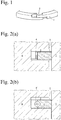
- the combined piston ring of the present invention comprises a piston ring body 1 having a step-shaped gap 2 exposed on upper and lower side surfaces and an outer peripheral surface.
- This gap shape is a so-called triple step shape having three steps on upper and lower side surfaces and an outer peripheral surface as shown in Fig. 1 , which can provide geometrically complete sealing. Accordingly, it can extremely reduce the amount of a blowby gas, thereby providing a piston ring with excellent gas sealability. Because it is extremely difficult to form a gap with such a complicated shape in a metal piston ring, a high-strength, heat-resistant resin is used in place of a metal in the present invention.
- the high-strength, heat-resistant resins preferably include superengineering plastics such as polyetheretherketone (PEEK) and polyphenylene sulfide (PPS), and further polybenzimidazole (PBI) having high heat resistance.
- PEEK polyetheretherketone
- PPS polyphenylene sulfide
- PBI polybenzimidazole
- These high-strength, heat-resistant resins can be injection-molded, easily forming a gap having a complicated shape.
- resin powder can be compression-molded to a ring shape, in which a gap can be formed by a thin-blade cutter.
- the above high-strength, heat-resistant resins may contain carbon fibers or glass fibers to increase heat resistance and strength, thereby providing fiber-reinforced, high-strength, heat-resistant resins.
- the proportions of such carbon fibers or glass fibers added are preferably 10-40% by weight.
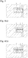
- Figs. 2(a) and 2(b) show the combined piston ring of the present invention received in a ring groove 5 of a piston 6, which is placed in a bore of a cylinder 7.
- the combined piston ring of the present invention comprises a piston ring body 1, and a spring 4 (4') for pushing the piston ring body 1 radially outward, a side surface of the piston ring body on the combustion chamber side being provided with a coating 3.
- the spring 4 (4') is a leaf spring 4 in Fig. 2(a)
- a coil spring 4' in Fig. 2(b) it is not restricted thereto as long as it has a function of pushing the piston ring body 1 radially outward.
- An outer peripheral surface 1 of the piston ring body which comes into sliding contact with a wall of the cylinder 7, may have various shapes such as a straight shape, a barrel-faced shape, a tapered shape, etc., depending on applications.
- the barrel face is preferable
- the tapered face is preferable.
- the coating 3 formed on the side surface of the piston ring body 1 on the combustion chamber side should have higher heat resistance than that of the piston ring body 1, such that it can fully withstand a burned gas, as described above. From the aspect of causing the thermal energy of the burned gas to escape not to the piston ring body 1 but to the cylinder bore, a high-thermal-conductivity coating is suitable. Oppositely, from the aspect of preventing the conduction of the thermal energy of the burned gas to the piston ring body 1, a low-thermal-conductivity coating is suitable. In any case, the coating 3 can be formed by brushing, spraying, dipping, plating, physical vapor deposition, chemical vapor deposition, etc.
- electroless plating is particularly convenient on a resin-made piston ring body.
- a metal plating of Cu or Ni or a composite plating comprising Cu or Ni and at least one selected from the group consisting of P, Co, Cr, Mo, Ti, SiC, Si 3 N 4 , Al 2 O 3 , B 4 C, diamond, PTFE (polytetrafluoroethylene), BN and graphite, as described above.
- the thickness of the electroless plating is preferably 1-50 ⁇ m, more preferably 5-30 ⁇ m.
- DLC can be formed by physical or chemical vapor deposition, and a layer having a structure close to diamond with a small hydrogen content can be formed by physical vapor deposition. From the aspect of productivity, the chemical vapor deposition is preferable.
- the thickness of the DLC coating is preferably 0.1-10 ⁇ m, more preferably 2-7 ⁇ m.
- Fig. 3 shows an embodiment in which an outer peripheral surface of the piston ring body 1 has a coating 3' of the same material as that of the coating 3 on a side surface on the combustion chamber side, such that the thermal energy of the burned gas escapes not to a piston ring body 1 but to a cylinder wall 7.
- a coating having low thermal conductivity a coating of polybenzimidazole (PBI), polyimide (PI) or organopolysiloxane (P-Si) is formed by brushing, spraying, dipping, etc.
- the thickness of the coating 3 is preferably 0.5-50 ⁇ m, more preferably 1-30 ⁇ m.
- this coating 3 is formed on at least a side surface on the combustion chamber side, it may of course be formed on other surfaces than the outer peripheral surface, taking into consideration productivity, etc.
- the outer peripheral surface which is subject to severe sliding, may be properly provided with a wear-resistant coating, whose material need not be the same as that of the coating 3 on the side surface on the combustion chamber side.
- Figs. 4(a) and 4(b) show the combined piston ring of the present invention, which further comprises a metal piston ring 8 thinner in width than the piston ring body on a side surface on the combustion chamber side.
- the thin metal piston ring 8 extremely reduces a thermal load to the piston ring body 1. Accordingly, this combined piston ring can be suitably used in a particularly severe condition, for example, for a top ring.
- the thin metal piston ring 8 usable is a piston ring with substantially no tension, which is known as a side rail of a combined oil ring. Fig.
- FIG. 4(a) shows an example using a leaf spring as the spring, which has such width as to push not only the piston ring body but also the thin metal piston ring 8 radially outward, resulting in a double sealing structure on the piston ring periphery capable of extremely reducing the blowby gas.
- Fig. 4(b) shows an example having only a function of simply heat-shielding the side surface of the piston ring body on the combustion chamber side without pushing the thin metal piston ring 8 radially outward. From the aspect of causing the thermal energy of the burned gas to escape to the cylinder bore, the thin metal piston ring 8 is preferably pushed radially outward, so that it comes into contact with the cylinder wall.
- Polyetheretherketone (PEEK) powder was blended with carbon fibers in an extruder to form a predetermined amount of pellets, which were then injection-molded to a piston ring having a straight outer periphery and a triple-step-shaped gap under predetermined conditions.
- a side surface of the piston ring had an arithmetic average surface roughness (Ra) of 0.4 ⁇ m.
- Ra arithmetic average surface roughness
- 50 piston rings in total suspended from a predetermined jig were subject to Ni-P electroless plating.
- the thickness of the resultant Ni-P coating was about 20 ⁇ m.
- a piston ring having a triple-step-shaped gap which was made of carbon-fiber-reinforced PEEK with one side surface having a Ni-P coating.
- the piston ring of Example 1 with a leaf spring set on the inner peripheral side for a tension of about 5 N was assembled in a top ring groove of each piston in a water-cooled, 4-cycle, naturally-aspirated gasoline engine, such that the Ni-P coating was disposed on the combustion chamber side, to measure the amount of blowby.
- a second ring and an oil ring were those assembled in this engine. The operation was conducted at 4,000 rpm under a wide open throttle (WOT) condition. Assuming that the amount of blowby in Comparative Example 1 below was 100, it was confirmed that the amount of blowby in Example 1 was about 12, reduction to about 1/8.
- WOT wide open throttle
- Piston rings of carbon-fiber-reinforced PEEK each having a triple-step-shaped gap were produced in the same manner as in Example 1, except for using electroless plating of Cu and Si 3 N 4 -dispersed composite electroless plating of Ni-P in place of the Ni-P electroless plating.
- the types and thicknesses of the coatings of Examples 2-3, their amounts of blowby by the engine test (1) at 4,000 rpm, and their surface roughness Rz and appearances on the side surfaces on the combustion chamber side before and after the engine test (2) are shown in Table 1, together with those of Example 1 and Comparative Example 2. It should be noted that the amount of blowby in each Example was expressed by a relative value to the amount of blowby in Comparative Example 1, which was 100.
- a piston ring of carbon-fiber-reinforced PEEK having a triple-step-shaped gap was produced in the same manner as in Example 1, except for forming a diamond-like carbon (DLC) coating by plasma CVD using a CH 4 gas as a starting material and an H 2 gas as a carrier gas in place of the Ni-P electroless plating.
- DLC diamond-like carbon
- a jig similar to the electroless plating jig in Example 1 was used.
- the outer peripheral surface of each piston ring was sealed by a heat-resistant tape.
- the results of the engine tests (1) and (2) are shown in Table 1.
- Each piston ring of carbon-fiber-reinforced PEEK having a triple-step-shaped gap was produced in the same manner as in Example 1, except for forming, in place of the Ni-P electroless plating, a resin coating comprising polybenzimidazole (PBI) or polyamide (PA) as a binder, in which 10% by mass of molybdenum disulfide was dispersed, by a printing method using a stencil mask.
- PBI polybenzimidazole
- PA polyamide
- the amount of blowby at 4,000 rpm was 13 or less in any of Examples 1-8 (E1-E8), assuming that it was 100 in Comparative Example 1, indicating drastically reduced blowby as compared with the straight-gap steel ring in Comparative Example 1 (C1).
- the piston rings each having a Ni-P electroless plating, a Cu electroless plating, an Si 3 N 4 -dispersed Ni-P electroless plating, a DLC coating, or a resin coating of PBI or PA on the side surface on the combustion chamber side passed the engine tests under relatively severe conditions, without damages and extreme roughening on the surface.
- the coating was formed not only on the side surface but also on the outer peripheral surface, the piston ring had further reduced blowby.
- a piston ring having the same size and shape as in Examples 1-8 (E1-E8) with the same Si 3 N 4 -dispersed Ni-P coating as in Example 3 formed on the side surface was produced in the same manner as in Example 1, except that it had a triple-step-shaped gap, a barrel-shaped outer peripheral wall and a groove for receiving a coil spring on the inner peripheral wall.
- the coating was as thick as 15 ⁇ m
- a coil spring for a tension of about 5 N set on the inner periphery of the piston ring each piston ring was assembled in the engine to conduct the engine tests (1) and (2) as in Examples 1-8. As a result, it exhibited blowby of 15 relative to the blowby (100) of Comparative Example 1, and surface roughness (Rz) of 2.4 ⁇ m and 2.5 ⁇ m before and after the test.
- Example 1 The carbon fiber-PEEK composite material pellets used in Example 1 were injection-molded to form a piston ring having a triple-step-shaped gap and a barrel-shaped outer peripheral wall, which was 4/5 as wide as the piston ring of Example 1. The same Si 3 N 4 /Ni-P composite plating as in Example 3 was formed on one side surface of this piston ring. Further, a small-width piston ring made of martensitic stainless steel, which was similar to a side rail in a combined oil control ring and 1/4 as wide as the piston ring body positioned below, was combined with the leaf spring used in Examples 1-8, and assembled in the same engine as in Examples 1-9.
- the combined piston ring of the present invention has a triple-step-shaped gap on upper and lower side surfaces and an outer peripheral surface, it has an extremely small gas-leaking area in the gap.
- its piston ring body is formed by an injection-molded, high-strength, heat-resistant resin, it is free from high production cost, breakage in a gap portion, etc.
- the piston ring body is subject to a reduced thermal load by a burned gas, so that it is free from local deformation and melting on the side surface on the combustion chamber side.
- the combined piston ring has excellent gas sealability.
Landscapes
- Engineering & Computer Science (AREA)
- General Engineering & Computer Science (AREA)
- Mechanical Engineering (AREA)
- Pistons, Piston Rings, And Cylinders (AREA)
Claims (7)
- Kombinierter Kolbenring, umfassend einen Kolbenring-Körper (1), der aus einem hochfesten, hitzebeständigen Harz hergestellt ist, und einen stufenförmigen Ausschnitt (2) und eine Feder (4,4') umfaßt, die an der inneren Umfangsseite des Kolbenring-Körpers (1) angeordnet ist, um den Kolbenring-Körper (1) radial nach außen zu drücken, dadurch gekennzeichnet, daß eine Beschichtung (3) wenigstens die Seitenfläche des Kolbenring-Körpers (1) auf der Seite der Verbrennungskammer überzieht, und das hochfeste, hitzebeständige Harz wenigstens ein Harz ist, das ausgewählt ist aus der Gruppe, die besteht aus Polyetheretherketon, Polyphenylensulfid und Polybenzimidazol, und der stufenförmige Ausschnitt (2) eine Tripelstufenform aufweist, die drei Stufen an oberen und unteren Seitenflächen und einer äußeren Umfangsfläche aufweist.
- Kombinierter Kolbenring nach Anspruch 1, worin das hochfeste, hitzebeständige Harz, das den Kolbenring-Körper (1) bildet, durch Carbonfasern oder Glasfasern verstärkt ist.
- Kombinierter Kolbenring nach Anspruch 1 oder Anspruch 2, worin die Beschichtung (3) eine Metall-Plattierung aus Cu oder Ni ist oder eine Verbund-Plattierung, die Cu oder Ni und wenigstens eine Komponente umfaßt, die ausgewählt ist aus der Gruppe, die besteht aus P, Co, Cr, Mo, Ti, SiC, Si3N4, Al2O3, B4C, Diamant, PTFE, BN und Graphit.
- Kombinierter Kolbenring nach irgendeinem der Ansprüche 1 bis 3, worin die Beschichtung (3) diamantartigen Kohlenstoff umfaßt.
- Kombinierter Kolbenring nach irgendeinem der Ansprüche 1 bis 4, worin die äußere Umfangsfläche des Kolbenring-Körpers (1) mit einer Beschichtung (3') desselben Materials überzogen ist wie dasjenige der Beschichtung (3).
- Kombinierter Kolbenring nach irgendeinem der Ansprüche 1 bis 5, worin die Beschichtung (3) wenigstens eine Komponente umfaßt, die ausgewählt ist aus der Gruppe, die besteht aus Polybenzimidazol, Polyimid und Organopolysiloxan.
- Kombinierter Kolbenring nach irgendeinem der Ansprüche 1 bis 6, worin ein Metall-Kolbenring (8), der eine kleinere Breite als diejenige des Kolbenring-Körpers aufweist, an der Seitenfläche des Kolbenring-Körpers auf der Seite der Verbrennungskammer angeordnet ist.
Applications Claiming Priority (2)
| Application Number | Priority Date | Filing Date | Title |
|---|---|---|---|
| JP2011021674A JP5658585B2 (ja) | 2011-02-03 | 2011-02-03 | 組合せピストンリング |
| PCT/JP2012/052098 WO2012105538A1 (ja) | 2011-02-03 | 2012-01-31 | 組合せピストンリング |
Publications (3)
| Publication Number | Publication Date |
|---|---|
| EP2672151A1 EP2672151A1 (de) | 2013-12-11 |
| EP2672151A4 EP2672151A4 (de) | 2015-02-18 |
| EP2672151B1 true EP2672151B1 (de) | 2017-05-10 |
Family
ID=46602750
Family Applications (1)
| Application Number | Title | Priority Date | Filing Date |
|---|---|---|---|
| EP12742580.9A Not-in-force EP2672151B1 (de) | 2011-02-03 | 2012-01-31 | Kombinierter kolbenring |
Country Status (7)
| Country | Link |
|---|---|
| US (1) | US20130305918A1 (de) |
| EP (1) | EP2672151B1 (de) |
| JP (1) | JP5658585B2 (de) |
| CN (1) | CN103339422B (de) |
| BR (1) | BR112013019833A2 (de) |
| MX (1) | MX2013009015A (de) |
| WO (1) | WO2012105538A1 (de) |
Families Citing this family (17)
| Publication number | Priority date | Publication date | Assignee | Title |
|---|---|---|---|---|
| US10041593B2 (en) | 2016-06-13 | 2018-08-07 | Hamilton Sundstrand Corporation | Piston ring assembly |
| JP6404976B2 (ja) | 2017-03-23 | 2018-10-17 | 株式会社リケン | ピストンリング |
| US10436322B2 (en) | 2017-08-09 | 2019-10-08 | Etagen, Inc. | Piston sealing ring assemblies |
| CA3072557A1 (en) | 2017-08-09 | 2019-02-14 | Mainspring Energy, Inc. | Sealing ring assemblies configured for pressure locking |
| CA3072568A1 (en) | 2017-08-09 | 2019-02-14 | Mainspring Energy, Inc. | Piston sealing ring assembly having a gap cover element |
| CN107503857B (zh) * | 2017-10-16 | 2023-12-05 | 湖南城市学院 | 内燃机活塞环组件 |
| JP7219537B2 (ja) * | 2017-11-29 | 2023-02-08 | 株式会社リケン | ピストンリングセット |
| JPWO2019124389A1 (ja) * | 2017-12-19 | 2020-07-16 | 株式会社リケン | 内燃機関用ピストンリング |
| CN107893849B (zh) * | 2017-12-20 | 2023-09-12 | 山东天瑞重工有限公司 | 水压凿岩机活塞及其制作方法 |
| JP7002401B2 (ja) * | 2018-04-27 | 2022-02-10 | 株式会社神戸製鋼所 | 圧縮機 |
| USD920408S1 (en) * | 2018-09-25 | 2021-05-25 | Kabushiki Kaisha Riken | Piston ring for internal combustion engine |
| US11060608B2 (en) * | 2019-02-07 | 2021-07-13 | Tenneco Inc. | Piston ring with inlaid DLC coating and method of manufacturing |
| JP7512017B2 (ja) * | 2019-04-26 | 2024-07-08 | 株式会社神戸製鋼所 | ピストンリング、往復動圧縮機及びピストンリングの選定方法 |
| CN112178107B (zh) * | 2019-07-05 | 2022-04-08 | 中国航发商用航空发动机有限责任公司 | 弹性组合式活塞环及其挤压油膜阻尼器 |
| US11326694B2 (en) * | 2019-12-17 | 2022-05-10 | Acd, Llc | Cryogenic piston ring improvement |
| JP7610968B2 (ja) * | 2020-12-17 | 2025-01-09 | マツダ株式会社 | 遮熱フィルム作製用の付加硬化型シリコーン樹脂、それを用いてエンジンの燃焼室の内面に遮熱フィルムを形成する方法、遮熱フィルム、およびそれを用いてエンジンの燃焼室から外部への放熱を防ぐ遮蔽方法 |
| CN114294418B (zh) * | 2021-12-08 | 2023-06-23 | 山东恒力源精密机械制造有限公司 | 一种活塞环及活塞环的制备方法 |
Family Cites Families (25)
| Publication number | Priority date | Publication date | Assignee | Title |
|---|---|---|---|---|
| FR1540312A (fr) * | 1967-02-17 | 1968-09-27 | Ensemble piston et segments pour moteur à combustion interne | |
| US3467397A (en) * | 1968-03-13 | 1969-09-16 | Nippon Piston Ring Co Ltd | Oil scraping ring combined with coiled expander |
| JPS51132311A (en) * | 1975-05-13 | 1976-11-17 | Nippon Piston Ring Co Ltd | Relative combination with cylinder and sealring of internal combustion engine |
| US4085490A (en) * | 1976-04-01 | 1978-04-25 | Ramsey Corporation | Method of making a rolled metal piston ring |
| JPS5412022A (en) * | 1977-06-25 | 1979-01-29 | Goetzewerke | Machine portion material exposed to wear that has coating layer on sliding surface in shape that riser portion is mounted to one side or both sides |
| JPS59126158U (ja) | 1983-02-12 | 1984-08-24 | 株式会社リケン | 往復動内燃機関用ピストン |
| JPS631964U (de) * | 1986-06-21 | 1988-01-08 | ||
| JP2554418Y2 (ja) * | 1990-08-06 | 1997-11-17 | 株式会社リケン | ピストンリング |
| JP3086383B2 (ja) * | 1994-09-09 | 2000-09-11 | 三菱電線工業株式会社 | ピストンリング及びその製造方法 |
| US5934680A (en) * | 1995-05-31 | 1999-08-10 | Ntn Corporation | Split resin seal ring with chamfered end connection structures |
| US5713324A (en) * | 1996-04-19 | 1998-02-03 | Dana Corporation | Piston ring coating |
| JP3255033B2 (ja) * | 1996-08-28 | 2002-02-12 | トヨタ自動車株式会社 | ピストンリング |
| JP4114849B2 (ja) | 2001-06-22 | 2008-07-09 | 株式会社リケン | シールリングの合口加工方法とそのための加工刃 |
| EP1564309B1 (de) * | 2002-10-15 | 2015-01-28 | Kabushiki Kaisha Riken | Kolbenring und thermische sprühbeschichtung dafür sowie zugehöriges herstellverfahren |
| JP2004353577A (ja) * | 2003-05-29 | 2004-12-16 | Toyoda Gosei Co Ltd | ピストンリングおよびそれを用いたピストン |
| US8033550B2 (en) * | 2005-05-26 | 2011-10-11 | Sulzer Metaplas Gmbh | Piston ring having hard multi-layer coating |
| JP2007192242A (ja) * | 2006-01-17 | 2007-08-02 | Mitsui Chemicals Inc | 溶融成形可能な熱可塑性ポリイミド樹脂からなるピストンリング |
| WO2007099968A1 (ja) * | 2006-02-28 | 2007-09-07 | Nippon Piston Ring Co., Ltd. | ピストンリング |
| US7943242B2 (en) * | 2006-03-30 | 2011-05-17 | Becton, Dickinson And Company | Sealing members, articles using the same and methods of reducing sticktion |
| US20100140880A1 (en) * | 2006-11-24 | 2010-06-10 | Toshikatsu Hayashi | Piston ring |
| WO2008072738A1 (ja) * | 2006-12-14 | 2008-06-19 | Nok Corporation | 密封装置及び密封装置の製造方法 |
| JP2008155125A (ja) * | 2006-12-22 | 2008-07-10 | Riken Corp | ピストンリング側面の塗装装置及び塗装法 |
| DE102008038636B4 (de) * | 2007-08-24 | 2012-10-25 | Nippon Piston Ring Co., Ltd. | Kolbenring |
| JP5021396B2 (ja) * | 2007-08-24 | 2012-09-05 | 日本ピストンリング株式会社 | ピストンリング |
| CN201193698Y (zh) * | 2008-03-25 | 2009-02-11 | 陈郁传 | 一种横竖拦截活塞环 |
-
2011
- 2011-02-03 JP JP2011021674A patent/JP5658585B2/ja not_active Expired - Fee Related
-
2012
- 2012-01-31 CN CN201280007530.8A patent/CN103339422B/zh not_active Expired - Fee Related
- 2012-01-31 US US13/983,529 patent/US20130305918A1/en not_active Abandoned
- 2012-01-31 EP EP12742580.9A patent/EP2672151B1/de not_active Not-in-force
- 2012-01-31 BR BR112013019833-8A patent/BR112013019833A2/pt not_active Application Discontinuation
- 2012-01-31 WO PCT/JP2012/052098 patent/WO2012105538A1/ja not_active Ceased
- 2012-01-31 MX MX2013009015A patent/MX2013009015A/es unknown
Also Published As
| Publication number | Publication date |
|---|---|
| CN103339422B (zh) | 2016-03-09 |
| US20130305918A1 (en) | 2013-11-21 |
| WO2012105538A1 (ja) | 2012-08-09 |
| EP2672151A1 (de) | 2013-12-11 |
| EP2672151A4 (de) | 2015-02-18 |
| JP5658585B2 (ja) | 2015-01-28 |
| BR112013019833A2 (pt) | 2020-11-17 |
| MX2013009015A (es) | 2013-08-29 |
| CN103339422A (zh) | 2013-10-02 |
| JP2012163118A (ja) | 2012-08-30 |
Similar Documents
| Publication | Publication Date | Title |
|---|---|---|
| EP2672151B1 (de) | Kombinierter kolbenring | |
| US8123227B2 (en) | Sliding member | |
| US7287459B2 (en) | Piston for internal combustion engine | |
| US8652620B2 (en) | Sliding element in an internal combustion engine, in particular a piston ring | |
| US10131988B2 (en) | Sliding element, in particular piston ring, and combination of a sliding element with a mating running element | |
| US9464717B2 (en) | Piston ring | |
| US11346332B2 (en) | Piston ring and compressor | |
| US10982767B2 (en) | Piston ring | |
| CN104854384B (zh) | 用于压力调节阀的密封圈 | |
| BRPI0509345B1 (pt) | processo para produção de um revestimento sobre um anel de pistão, bem como anel de pistão | |
| US10927953B2 (en) | Piston seal with solid lubricant applicator | |
| US20150240945A1 (en) | Three-piece oil ring for internal combustion engines, expanding element, and annular element | |
| US11739840B2 (en) | Piston ring | |
| JP5376668B2 (ja) | ピストンリング | |
| BR102016017735A2 (pt) | Elemento deslizante para motores de combustão interna | |
| JP7219537B2 (ja) | ピストンリングセット | |
| US20050067790A1 (en) | Piston ring having chromium coating | |
| CA2707438C (en) | Layered metallic gasket | |
| JP7659098B1 (ja) | 水素燃料を使用する内燃機関用のピストンリングセット並びにピストンリング、及び水素燃料を使用する内燃機関における堆積物の生成抑制方法 | |
| JPWO2019124389A1 (ja) | 内燃機関用ピストンリング | |
| DAY | Piston ring and liner wear |
Legal Events
| Date | Code | Title | Description |
|---|---|---|---|
| PUAI | Public reference made under article 153(3) epc to a published international application that has entered the european phase |
Free format text: ORIGINAL CODE: 0009012 |
|
| 17P | Request for examination filed |
Effective date: 20130806 |
|
| AK | Designated contracting states |
Kind code of ref document: A1 Designated state(s): AL AT BE BG CH CY CZ DE DK EE ES FI FR GB GR HR HU IE IS IT LI LT LU LV MC MK MT NL NO PL PT RO RS SE SI SK SM TR |
|
| DAX | Request for extension of the european patent (deleted) | ||
| A4 | Supplementary search report drawn up and despatched |
Effective date: 20150116 |
|
| RIC1 | Information provided on ipc code assigned before grant |
Ipc: F16J 9/26 20060101AFI20150112BHEP Ipc: F16J 9/14 20060101ALI20150112BHEP Ipc: F16J 9/06 20060101ALI20150112BHEP Ipc: F02F 5/00 20060101ALI20150112BHEP Ipc: F16J 9/28 20060101ALI20150112BHEP |
|
| GRAP | Despatch of communication of intention to grant a patent |
Free format text: ORIGINAL CODE: EPIDOSNIGR1 |
|
| RIC1 | Information provided on ipc code assigned before grant |
Ipc: F16J 9/06 20060101ALI20161121BHEP Ipc: F16J 9/28 20060101ALI20161121BHEP Ipc: F16J 9/26 20060101AFI20161121BHEP Ipc: F16J 9/14 20060101ALI20161121BHEP Ipc: F02F 5/00 20060101ALI20161121BHEP |
|
| INTG | Intention to grant announced |
Effective date: 20161223 |
|
| GRAS | Grant fee paid |
Free format text: ORIGINAL CODE: EPIDOSNIGR3 |
|
| GRAA | (expected) grant |
Free format text: ORIGINAL CODE: 0009210 |
|
| AK | Designated contracting states |
Kind code of ref document: B1 Designated state(s): AL AT BE BG CH CY CZ DE DK EE ES FI FR GB GR HR HU IE IS IT LI LT LU LV MC MK MT NL NO PL PT RO RS SE SI SK SM TR |
|
| REG | Reference to a national code |
Ref country code: GB Ref legal event code: FG4D |
|
| REG | Reference to a national code |
Ref country code: AT Ref legal event code: REF Ref document number: 892690 Country of ref document: AT Kind code of ref document: T Effective date: 20170515 Ref country code: CH Ref legal event code: EP |
|
| REG | Reference to a national code |
Ref country code: IE Ref legal event code: FG4D |
|
| REG | Reference to a national code |
Ref country code: DE Ref legal event code: R096 Ref document number: 602012032254 Country of ref document: DE |
|
| REG | Reference to a national code |
Ref country code: NL Ref legal event code: MP Effective date: 20170510 |
|
| REG | Reference to a national code |
Ref country code: LT Ref legal event code: MG4D |
|
| REG | Reference to a national code |
Ref country code: AT Ref legal event code: MK05 Ref document number: 892690 Country of ref document: AT Kind code of ref document: T Effective date: 20170510 |
|
| PG25 | Lapsed in a contracting state [announced via postgrant information from national office to epo] |
Ref country code: HR Free format text: LAPSE BECAUSE OF FAILURE TO SUBMIT A TRANSLATION OF THE DESCRIPTION OR TO PAY THE FEE WITHIN THE PRESCRIBED TIME-LIMIT Effective date: 20170510 Ref country code: LT Free format text: LAPSE BECAUSE OF FAILURE TO SUBMIT A TRANSLATION OF THE DESCRIPTION OR TO PAY THE FEE WITHIN THE PRESCRIBED TIME-LIMIT Effective date: 20170510 Ref country code: AT Free format text: LAPSE BECAUSE OF FAILURE TO SUBMIT A TRANSLATION OF THE DESCRIPTION OR TO PAY THE FEE WITHIN THE PRESCRIBED TIME-LIMIT Effective date: 20170510 Ref country code: GR Free format text: LAPSE BECAUSE OF FAILURE TO SUBMIT A TRANSLATION OF THE DESCRIPTION OR TO PAY THE FEE WITHIN THE PRESCRIBED TIME-LIMIT Effective date: 20170811 Ref country code: NO Free format text: LAPSE BECAUSE OF FAILURE TO SUBMIT A TRANSLATION OF THE DESCRIPTION OR TO PAY THE FEE WITHIN THE PRESCRIBED TIME-LIMIT Effective date: 20170810 Ref country code: FI Free format text: LAPSE BECAUSE OF FAILURE TO SUBMIT A TRANSLATION OF THE DESCRIPTION OR TO PAY THE FEE WITHIN THE PRESCRIBED TIME-LIMIT Effective date: 20170510 Ref country code: ES Free format text: LAPSE BECAUSE OF FAILURE TO SUBMIT A TRANSLATION OF THE DESCRIPTION OR TO PAY THE FEE WITHIN THE PRESCRIBED TIME-LIMIT Effective date: 20170510 |
|
| PG25 | Lapsed in a contracting state [announced via postgrant information from national office to epo] |
Ref country code: BG Free format text: LAPSE BECAUSE OF FAILURE TO SUBMIT A TRANSLATION OF THE DESCRIPTION OR TO PAY THE FEE WITHIN THE PRESCRIBED TIME-LIMIT Effective date: 20170810 Ref country code: IS Free format text: LAPSE BECAUSE OF FAILURE TO SUBMIT A TRANSLATION OF THE DESCRIPTION OR TO PAY THE FEE WITHIN THE PRESCRIBED TIME-LIMIT Effective date: 20170910 Ref country code: SE Free format text: LAPSE BECAUSE OF FAILURE TO SUBMIT A TRANSLATION OF THE DESCRIPTION OR TO PAY THE FEE WITHIN THE PRESCRIBED TIME-LIMIT Effective date: 20170510 Ref country code: NL Free format text: LAPSE BECAUSE OF FAILURE TO SUBMIT A TRANSLATION OF THE DESCRIPTION OR TO PAY THE FEE WITHIN THE PRESCRIBED TIME-LIMIT Effective date: 20170510 Ref country code: RS Free format text: LAPSE BECAUSE OF FAILURE TO SUBMIT A TRANSLATION OF THE DESCRIPTION OR TO PAY THE FEE WITHIN THE PRESCRIBED TIME-LIMIT Effective date: 20170510 Ref country code: LV Free format text: LAPSE BECAUSE OF FAILURE TO SUBMIT A TRANSLATION OF THE DESCRIPTION OR TO PAY THE FEE WITHIN THE PRESCRIBED TIME-LIMIT Effective date: 20170510 Ref country code: PL Free format text: LAPSE BECAUSE OF FAILURE TO SUBMIT A TRANSLATION OF THE DESCRIPTION OR TO PAY THE FEE WITHIN THE PRESCRIBED TIME-LIMIT Effective date: 20170510 |
|
| PG25 | Lapsed in a contracting state [announced via postgrant information from national office to epo] |
Ref country code: DK Free format text: LAPSE BECAUSE OF FAILURE TO SUBMIT A TRANSLATION OF THE DESCRIPTION OR TO PAY THE FEE WITHIN THE PRESCRIBED TIME-LIMIT Effective date: 20170510 Ref country code: CZ Free format text: LAPSE BECAUSE OF FAILURE TO SUBMIT A TRANSLATION OF THE DESCRIPTION OR TO PAY THE FEE WITHIN THE PRESCRIBED TIME-LIMIT Effective date: 20170510 Ref country code: SK Free format text: LAPSE BECAUSE OF FAILURE TO SUBMIT A TRANSLATION OF THE DESCRIPTION OR TO PAY THE FEE WITHIN THE PRESCRIBED TIME-LIMIT Effective date: 20170510 Ref country code: RO Free format text: LAPSE BECAUSE OF FAILURE TO SUBMIT A TRANSLATION OF THE DESCRIPTION OR TO PAY THE FEE WITHIN THE PRESCRIBED TIME-LIMIT Effective date: 20170510 Ref country code: EE Free format text: LAPSE BECAUSE OF FAILURE TO SUBMIT A TRANSLATION OF THE DESCRIPTION OR TO PAY THE FEE WITHIN THE PRESCRIBED TIME-LIMIT Effective date: 20170510 |
|
| REG | Reference to a national code |
Ref country code: DE Ref legal event code: R097 Ref document number: 602012032254 Country of ref document: DE |
|
| PG25 | Lapsed in a contracting state [announced via postgrant information from national office to epo] |
Ref country code: IT Free format text: LAPSE BECAUSE OF FAILURE TO SUBMIT A TRANSLATION OF THE DESCRIPTION OR TO PAY THE FEE WITHIN THE PRESCRIBED TIME-LIMIT Effective date: 20170510 Ref country code: SM Free format text: LAPSE BECAUSE OF FAILURE TO SUBMIT A TRANSLATION OF THE DESCRIPTION OR TO PAY THE FEE WITHIN THE PRESCRIBED TIME-LIMIT Effective date: 20170510 |
|
| PLBE | No opposition filed within time limit |
Free format text: ORIGINAL CODE: 0009261 |
|
| STAA | Information on the status of an ep patent application or granted ep patent |
Free format text: STATUS: NO OPPOSITION FILED WITHIN TIME LIMIT |
|
| 26N | No opposition filed |
Effective date: 20180213 |
|
| PG25 | Lapsed in a contracting state [announced via postgrant information from national office to epo] |
Ref country code: SI Free format text: LAPSE BECAUSE OF FAILURE TO SUBMIT A TRANSLATION OF THE DESCRIPTION OR TO PAY THE FEE WITHIN THE PRESCRIBED TIME-LIMIT Effective date: 20170510 |
|
| REG | Reference to a national code |
Ref country code: CH Ref legal event code: PL |
|
| GBPC | Gb: european patent ceased through non-payment of renewal fee |
Effective date: 20180131 |
|
| PG25 | Lapsed in a contracting state [announced via postgrant information from national office to epo] |
Ref country code: FR Free format text: LAPSE BECAUSE OF NON-PAYMENT OF DUE FEES Effective date: 20180131 Ref country code: LU Free format text: LAPSE BECAUSE OF NON-PAYMENT OF DUE FEES Effective date: 20180131 |
|
| REG | Reference to a national code |
Ref country code: IE Ref legal event code: MM4A |
|
| REG | Reference to a national code |
Ref country code: FR Ref legal event code: ST Effective date: 20180928 |
|
| REG | Reference to a national code |
Ref country code: BE Ref legal event code: MM Effective date: 20180131 |
|
| PG25 | Lapsed in a contracting state [announced via postgrant information from national office to epo] |
Ref country code: BE Free format text: LAPSE BECAUSE OF NON-PAYMENT OF DUE FEES Effective date: 20180131 Ref country code: LI Free format text: LAPSE BECAUSE OF NON-PAYMENT OF DUE FEES Effective date: 20180131 Ref country code: GB Free format text: LAPSE BECAUSE OF NON-PAYMENT OF DUE FEES Effective date: 20180131 Ref country code: CH Free format text: LAPSE BECAUSE OF NON-PAYMENT OF DUE FEES Effective date: 20180131 |
|
| PG25 | Lapsed in a contracting state [announced via postgrant information from national office to epo] |
Ref country code: IE Free format text: LAPSE BECAUSE OF NON-PAYMENT OF DUE FEES Effective date: 20180131 |
|
| PG25 | Lapsed in a contracting state [announced via postgrant information from national office to epo] |
Ref country code: MC Free format text: LAPSE BECAUSE OF FAILURE TO SUBMIT A TRANSLATION OF THE DESCRIPTION OR TO PAY THE FEE WITHIN THE PRESCRIBED TIME-LIMIT Effective date: 20170510 |
|
| PG25 | Lapsed in a contracting state [announced via postgrant information from national office to epo] |
Ref country code: MT Free format text: LAPSE BECAUSE OF NON-PAYMENT OF DUE FEES Effective date: 20180131 |
|
| PG25 | Lapsed in a contracting state [announced via postgrant information from national office to epo] |
Ref country code: TR Free format text: LAPSE BECAUSE OF FAILURE TO SUBMIT A TRANSLATION OF THE DESCRIPTION OR TO PAY THE FEE WITHIN THE PRESCRIBED TIME-LIMIT Effective date: 20170510 |
|
| PG25 | Lapsed in a contracting state [announced via postgrant information from national office to epo] |
Ref country code: PT Free format text: LAPSE BECAUSE OF FAILURE TO SUBMIT A TRANSLATION OF THE DESCRIPTION OR TO PAY THE FEE WITHIN THE PRESCRIBED TIME-LIMIT Effective date: 20170510 Ref country code: HU Free format text: LAPSE BECAUSE OF FAILURE TO SUBMIT A TRANSLATION OF THE DESCRIPTION OR TO PAY THE FEE WITHIN THE PRESCRIBED TIME-LIMIT; INVALID AB INITIO Effective date: 20120131 |
|
| PG25 | Lapsed in a contracting state [announced via postgrant information from national office to epo] |
Ref country code: MK Free format text: LAPSE BECAUSE OF NON-PAYMENT OF DUE FEES Effective date: 20170510 Ref country code: CY Free format text: LAPSE BECAUSE OF FAILURE TO SUBMIT A TRANSLATION OF THE DESCRIPTION OR TO PAY THE FEE WITHIN THE PRESCRIBED TIME-LIMIT Effective date: 20170510 |
|
| PG25 | Lapsed in a contracting state [announced via postgrant information from national office to epo] |
Ref country code: AL Free format text: LAPSE BECAUSE OF FAILURE TO SUBMIT A TRANSLATION OF THE DESCRIPTION OR TO PAY THE FEE WITHIN THE PRESCRIBED TIME-LIMIT Effective date: 20170510 |
|
| PGFP | Annual fee paid to national office [announced via postgrant information from national office to epo] |
Ref country code: DE Payment date: 20210119 Year of fee payment: 10 |
|
| REG | Reference to a national code |
Ref country code: DE Ref legal event code: R119 Ref document number: 602012032254 Country of ref document: DE |
|
| PG25 | Lapsed in a contracting state [announced via postgrant information from national office to epo] |
Ref country code: DE Free format text: LAPSE BECAUSE OF NON-PAYMENT OF DUE FEES Effective date: 20220802 |