EP2672046A2 - Guide rail assembly - Google Patents
Guide rail assembly Download PDFInfo
- Publication number
- EP2672046A2 EP2672046A2 EP13002216.3A EP13002216A EP2672046A2 EP 2672046 A2 EP2672046 A2 EP 2672046A2 EP 13002216 A EP13002216 A EP 13002216A EP 2672046 A2 EP2672046 A2 EP 2672046A2
- Authority
- EP
- European Patent Office
- Prior art keywords
- guide rail
- latching
- door
- axis
- mounting surface
- Prior art date
- Legal status (The legal status is an assumption and is not a legal conclusion. Google has not performed a legal analysis and makes no representation as to the accuracy of the status listed.)
- Withdrawn
Links
Images


Classifications
-
- E—FIXED CONSTRUCTIONS
- E05—LOCKS; KEYS; WINDOW OR DOOR FITTINGS; SAFES
- E05F—DEVICES FOR MOVING WINGS INTO OPEN OR CLOSED POSITION; CHECKS FOR WINGS; WING FITTINGS NOT OTHERWISE PROVIDED FOR, CONCERNED WITH THE FUNCTIONING OF THE WING
- E05F3/00—Closers or openers with braking devices, e.g. checks; Construction of pneumatic or liquid braking devices
- E05F3/22—Additional arrangements for closers, e.g. for holding the wing in opened or other position
- E05F3/221—Mechanical power-locks, e.g. for holding the wing open or for free-moving zones
-
- E—FIXED CONSTRUCTIONS
- E05—LOCKS; KEYS; WINDOW OR DOOR FITTINGS; SAFES
- E05C—BOLTS OR FASTENING DEVICES FOR WINGS, SPECIALLY FOR DOORS OR WINDOWS
- E05C17/00—Devices for holding wings open; Devices for limiting opening of wings or for holding wings open by a movable member extending between frame and wing; Braking devices, stops or buffers, combined therewith
- E05C17/02—Devices for holding wings open; Devices for limiting opening of wings or for holding wings open by a movable member extending between frame and wing; Braking devices, stops or buffers, combined therewith by mechanical means
- E05C17/04—Devices for holding wings open; Devices for limiting opening of wings or for holding wings open by a movable member extending between frame and wing; Braking devices, stops or buffers, combined therewith by mechanical means with a movable bar or equivalent member extending between frame and wing
- E05C17/12—Devices for holding wings open; Devices for limiting opening of wings or for holding wings open by a movable member extending between frame and wing; Braking devices, stops or buffers, combined therewith by mechanical means with a movable bar or equivalent member extending between frame and wing consisting of a single rod
- E05C17/24—Devices for holding wings open; Devices for limiting opening of wings or for holding wings open by a movable member extending between frame and wing; Braking devices, stops or buffers, combined therewith by mechanical means with a movable bar or equivalent member extending between frame and wing consisting of a single rod pivoted at one end, and with the other end running along a guide member
- E05C17/28—Devices for holding wings open; Devices for limiting opening of wings or for holding wings open by a movable member extending between frame and wing; Braking devices, stops or buffers, combined therewith by mechanical means with a movable bar or equivalent member extending between frame and wing consisting of a single rod pivoted at one end, and with the other end running along a guide member with braking, clamping or securing means at the connection to the guide member
-
- E—FIXED CONSTRUCTIONS
- E05—LOCKS; KEYS; WINDOW OR DOOR FITTINGS; SAFES
- E05D—HINGES OR SUSPENSION DEVICES FOR DOORS, WINDOWS OR WINGS
- E05D13/00—Accessories for sliding or lifting wings, e.g. pulleys, safety catches
- E05D13/04—Fasteners specially adapted for holding sliding wings open
-
- E—FIXED CONSTRUCTIONS
- E05—LOCKS; KEYS; WINDOW OR DOOR FITTINGS; SAFES
- E05F—DEVICES FOR MOVING WINGS INTO OPEN OR CLOSED POSITION; CHECKS FOR WINGS; WING FITTINGS NOT OTHERWISE PROVIDED FOR, CONCERNED WITH THE FUNCTIONING OF THE WING
- E05F3/00—Closers or openers with braking devices, e.g. checks; Construction of pneumatic or liquid braking devices
- E05F3/22—Additional arrangements for closers, e.g. for holding the wing in opened or other position
- E05F2003/228—Arrangements where the end of the closer arm is sliding in a track
-
- E—FIXED CONSTRUCTIONS
- E05—LOCKS; KEYS; WINDOW OR DOOR FITTINGS; SAFES
- E05Y—INDEXING SCHEME RELATING TO HINGES OR OTHER SUSPENSION DEVICES FOR DOORS, WINDOWS OR WINGS AND DEVICES FOR MOVING WINGS INTO OPEN OR CLOSED POSITION, CHECKS FOR WINGS AND WING FITTINGS NOT OTHERWISE PROVIDED FOR, CONCERNED WITH THE FUNCTIONING OF THE WING
- E05Y2201/00—Constructional elements; Accessories therefore
- E05Y2201/20—Brakes; Disengaging means, e.g. clutches; Holders, e.g. locks; Stops; Accessories therefore
- E05Y2201/218—Holders
-
- E—FIXED CONSTRUCTIONS
- E05—LOCKS; KEYS; WINDOW OR DOOR FITTINGS; SAFES
- E05Y—INDEXING SCHEME RELATING TO HINGES OR OTHER SUSPENSION DEVICES FOR DOORS, WINDOWS OR WINGS AND DEVICES FOR MOVING WINGS INTO OPEN OR CLOSED POSITION, CHECKS FOR WINGS AND WING FITTINGS NOT OTHERWISE PROVIDED FOR, CONCERNED WITH THE FUNCTIONING OF THE WING
- E05Y2201/00—Constructional elements; Accessories therefore
- E05Y2201/60—Suspension or transmission members; Accessories therefore
- E05Y2201/622—Suspension or transmission members elements
- E05Y2201/684—Rails
-
- E—FIXED CONSTRUCTIONS
- E05—LOCKS; KEYS; WINDOW OR DOOR FITTINGS; SAFES
- E05Y—INDEXING SCHEME RELATING TO HINGES OR OTHER SUSPENSION DEVICES FOR DOORS, WINDOWS OR WINGS AND DEVICES FOR MOVING WINGS INTO OPEN OR CLOSED POSITION, CHECKS FOR WINGS AND WING FITTINGS NOT OTHERWISE PROVIDED FOR, CONCERNED WITH THE FUNCTIONING OF THE WING
- E05Y2900/00—Application of doors, windows, wings or fittings thereof
- E05Y2900/10—Application of doors, windows, wings or fittings thereof for buildings or parts thereof
- E05Y2900/13—Application of doors, windows, wings or fittings thereof for buildings or parts thereof characterised by the type of wing
- E05Y2900/132—Doors
Definitions
- the present invention relates to a guide rail assembly for a door.
- the guide rail arrangement serves to fix a door leaf in a specific position.
- the invention covers a door operator assembly with a guide rail assembly.
- Swing doors are usually operated with a door closer or a door drive (generally: door operator).
- the door operator is either stationary on the wall or frame or directly on the door leaf. If the door operator is located on the door leaf by way of example, the force is transmitted from the output shaft of the door operator via a lever to a movement element (also: sliding piece). This movement element is linearly guided in the guide rail (also slide), which is fixed to the wall or frame. In order to fix the door leaf in its position, the moving element is fixed by means of a locking device in the guide rail.
- the door closer or door drive can also be fixed to the wall or frame.
- the guide rail is attached to the door leaf.
- sliding doors which are guided linearly movable in guide rails.
- a moving element is guided in the guide rail.
- the moving element is fixed in the guide rail.
- the guide rail assembly should be able to be integrated into the frame of a door.
- a guide rail arrangement for a door comprising a guide rail with a mounting surface for mounting on a door leaf, a frame or a wall. Furthermore, a linearly movably guided movement element is provided in the guide rail. The moving element is movable along a direction of movement. With the moving element a latch is firmly connected. Furthermore, a latching detent is fixed in the guide rail. This detent locking serves to lock the movement element relative to the guide rail.
- the latching detent comprises a second latching nose rotatably mounted about an axis of rotation. This second latching lug is designed to be complementary to the first latching lug and can thus engage and disengage at the first latching lug.
- a spring in particular a helical compression spring, is provided in the latching detent.
- the spring loads the second latching lug, so that the second latching lug is rotated against the force of the spring about the axis of rotation during engagement and disengagement.
- the guide rail assembly according to the invention should be very narrow in both the horizontal and in the vertical direction, so that it can be integrated into the frame of a door leaf or into the frame of a door.
- the mounting surface described above is preferably defined as a horizontal plane. Both parallel to this plane and perpendicular The structure should be as small as possible to this level. For this purpose, it is defined that the axis of rotation of the second latching lug is arranged parallel to the mounting surface.
- the second latching nose pivots perpendicular to the mounting surface. That is, when engaging and disengaging the second locking lug moves perpendicular to the mounting surface, so that changes the distance between the mounting surface and the second locking lug when engaging and disengaging.
- This has a very narrow structure, especially in the direction parallel to the mounting surface result.
- the axis of rotation of the second latching lug is arranged perpendicular to a direction of movement of the moving element.
- the direction of movement of the movement element extends parallel to the mounting surface.
- an eye is formed in the movement element.
- the entire guide rail arrangement for a door operator such as a door closer or door drive, can be used.
- the eye in the moving element is designed to connect a first end of a lever, wherein the other end of the lever is connected to a door operator.
- the axis of the eye in particular the rotational symmetry axis of the eye, is perpendicular to the mounting surface and perpendicular to the axis of rotation of the second latching lug.
- first latching nose is rigidly connected to the moving element.
- This "rigid connection” means that no pivot or rotation axis is provided between the first latching lug and the moving element.
- the detent locking comprises an L-shaped rocker arm with two ends. At one end, the second detent is formed and at the other end of the rocker arm, the axis of rotation is arranged. Between the two ends, in particular at the bend of the L, the spring attacks.
- the second latching lug is particularly preferably designed as a rotating roller. The axis of rotation of this rotating roller is arranged parallel to the axis of rotation of the second latching lug.
- a plunger is provided. This plunger is firmly connected to the spring and presses on the rocker arm.
- the latching detent comprises a block for supporting the rocker arm and for supporting the spring.
- the plunger is mounted in the block.
- the position of the detent locking within the guide rail specifies at which angle the door can be detected. Therefore, it is preferably provided that the detent locking can be set at different, in particular arbitrary, positions within the guide rail. In particular, two variants are provided for this determination.
- the block can be fixed directly to the guide rail by means of a screw connection.
- a carriage in particular a carriage made of sheet metal, is provided. The block is mounted on the carriage and the carriage is in turn fixed within the guide rail.
- the carriage for example by means of guide jaws, is guided linearly movable in the slide rail.
- the guide rail is formed as follows:
- the guide rail has the above-described mounting surface.
- the mounting surface Perpendicular to the mounting surface are two opposite side walls. Between these two side walls, the moving element is guided. Furthermore, the mounting surface has at least one mounting hole. About this mounting hole can, for example by means of a screw, the guide rail to a wall, a frame or a door are attached. The mounting surface rests on the surface to which the guide rail is attached.
- the invention further includes a door operator assembly for moving and securing a door leaf.
- This door operator assembly comprises one of the guide rail assemblies just described, a door operator having an output shaft, and a lever.
- the door operator is in particular a door closer or door drive.
- the lever is rotatably connected at one end to the output shaft.
- the other end of the lever is rotatably connected to the moving member.
- the lever is here rotatably connected via the eye of the movement element.
- the rotatable connection between the lever and the moving element is rotatable about an axis perpendicular to the mounting surface. This axis is also perpendicular to the direction of movement of the moving element and perpendicular to the axis of rotation of the second latching lug.
- the door operator is preferably integrated into the frame of the door leaf.
- the guide rail arrangement is preferably integrated in the frame of the door frame.
- the axis of rotation of the second latching lug in the latching detent is arranged perpendicular to the direction of movement of the moving element and parallel to the mounting surface. This has the consequence that the second latching nose moves during engagement and disengagement in the direction perpendicular to the mounting surface.
- the arrangement of the axis of rotation thus has a very narrow structure in the direction parallel to the mounting surface result. Note, however, the space in the direction perpendicular to the mounting surface, since the second latch pivots in this direction.
- an extension is arranged between the movement element and the first latching lug.
- This extension is firmly connected to the movement element and fixed to the locking lug. Because of this extension, the latching detent can be arranged as close as possible to the pivot axis of the door leaf. As a result, in the closed state of the door leaf, the lever has sufficient space between the latching position and the moving element. The length of the extension is thus chosen so long that in the closed state of the door leaf, the output shaft of the door operator between the moving element and the locking detent is arranged.
- the extension is so long that, in the closed state of the door leaf, the output shaft of the door operator finds place between the movement element and the block of the latching detent. Since the two locking lugs are not engaged in the closed state, the second locking lug, in particular the rocker arm is lowered. Therefore, in this state, the lever connecting the output shaft to the moving member may slightly overlap with the rocker arm. However, the block, in particular the two protruding ridges of the block of the locking detent are too large in the direction perpendicular to the mounting surface building that the extension must ensure a distance to the lever here.
- the extension is detachably mounted with the first latching lug and / or the moving element. This makes it easy to set the desired angle at which the door should be locked.
- a positive or non-positive connection between the movement element and extension and / or between the first latching lug and extension is provided.
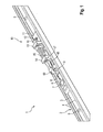
- the guide rail arrangement 1 comprises a guide rail 2, designed as a slide rail.
- the guide rail 2 has a mounting surface 3 with a plurality of mounting holes 5. About this mounting holes 5, the guide rail 2 can be screwed to a frame, a door or wall. Perpendicular to the mounting surface 3 are two spaced side walls. 4
- a moving element 6 is guided in the direction of movement 8 linearly movable in the guide rail 2.
- an eye 7 is formed in the moving element 6.
- the movement element 6 is fixedly connected to a first latching lug 9.
- a detent 10 located in the guide rail 2, a detent 10.
- This detent 10 is guided linearly movable within the guide rail 2.
- the latching detent 10 is fixed in the guide rail 2.
- the latching detent 10 comprises a block 11, which is fixed in the guide rail 2 via a screw 12.
- the block 11 comprises a first web 13 and a second web 14.
- the two webs 13, 14 extend in a direction perpendicular to the mounting surface 3.
- a through hole is provided in each of the two webs 13, 14, a through hole is provided. The through holes extend parallel to the direction of movement 8.
- a coil spring 15 is arranged between the two webs 13, 14 .
- the coil spring 15 is mounted at one end via a spring force adjustment 16 in the first block 13.
- the other end of the spring 15 is stuck on a plunger 17.
- the plunger 17 is mounted linearly movable in the second web 14.
- the latching detent 10 has a rocker arm 18. At this rocker arm 18, a second latching lug 19 is formed.
- the second latching lug 19 is formed as a roller.
- the second latching lug 19 can engage and disengage with the first latching lug 9. In this case, only the second locking lug 19 pivots.
- FIG. 2 shows a detail FIG. 1 , In FIG. 2 the guide rail 2 and the block 11 are hidden. This makes it easy to see that the rocker arm 19 is L-shaped. At one end of the L, the second locking lug 19 is arranged. The other end of the L-shaped rocker arm 18 has an axis of rotation 20. The axis of rotation 20 extends parallel to the mounting surface 3 and perpendicular to the direction of movement 8. The plunger 17 presses against the rocker arm 18 so that upon engagement and disengagement of the two locking lugs 9, 19 of the rocker arm 18 and thus also the second latching lug 19 against the spring force the spring 15 is moved.
- FIG. 2 an axis 21 of the eye 7. This axis 21 is perpendicular to the direction of movement 8 and perpendicular to the mounting surface. 3
- FIG. 3 shows a second embodiment of the guide rail assembly 1.
- the guide rail 2 is hidden here.
- Identical or functionally identical components are provided with the same reference numerals in all embodiments.
- the block 11 is fixed directly on the screw 12 in the guide rail 2.
- a plate carriage 22 is provided. This plate carriage 22 is fixed via the screw 12 in the guide rail 2.
- two upwardly bent screw fastening tongues 24 are provided on the plate carriage 22.
- the block 11 is seated between these two screw connection lugs 24.
- the block 11 is firmly connected to the plate carriage 22 via a slide screw connection 24 which passes through the two screw connection lugs 24.
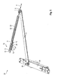
- FIGS. 4 and 5 show a Matbetuschigeran Aunt 26.
- the door actuator assembly 26 includes a door operator 29, designed as a door closer, a lever 31 and a guide rail assembly 1, as just described.
- FIG. 4 shows the door operator 29 is embedded or integrated into the frame of a door leaf 28.
- the guide rail assembly 1 is inserted or integrated into the frame of a door frame 27.
- FIG. 5 the door frame 27 and the door leaf 28 are hidden.
- the door operator 29 includes an output shaft 30.
- This output shaft 30 is rotatably connected to the lever 31.
- the other end of the lever 31 is rotatably connected via the eye 7 with the moving member 6. In the closed state of the door leaf 28, the entire Matrix Aunt 26 is not visible.
- FIG. 5 shows that the guide rail assembly 1 comprises an extension 32.
- This extension 32 is connected at one end to the moving element 6 and at the other end to the first latching lug 9.
- a sliding attachment 33 is pushed onto the extension 32, so that the extension 32 is supported via the sliding attachment 33 in the guide rail 2.
- the moving element 6 moves to the right and the lever 31 is arranged parallel to the guide rail 2 at.
- the extension 32 is provided so that the latching detent 10 can be offset as far as possible to the left.
- the length of the extension 32 must in particular be chosen so that in the closed state, the output shaft 33 between the latching detent 10 and the moving element 6 finds room.
Abstract
Description
Vorliegende Erfindung betrifft eine Führungsschienenanordnung für eine Tür. Insbesondere dient die Führungsschienenanordnung dazu, einen Türflügel in einer bestimmten Position zu fixieren. Des Weiteren erfasst die Erfindung eine Türbetätigeranordnung mit einer Führungsschienenanordnung.The present invention relates to a guide rail assembly for a door. In particular, the guide rail arrangement serves to fix a door leaf in a specific position. Furthermore, the invention covers a door operator assembly with a guide rail assembly.
Führungsschienenanordnungen kommen im Stand der Technik in Verbindung mit Türschließern oder Türantrieben zum Einsatz. Darüber hinaus gibt es Führungsschienenanordnungen in Verbindung mit Schiebetüren. Drehflügeltüren werden in der Regel mit einem Türschließer oder einem Türantrieb (allgemein: Türbetätiger) betätigt. Dabei befindet sich der Türbetätiger entweder ortsfest an der Wand oder Zarge oder direkt am Türflügel. Befindet sich der Türbetätiger beispielhaft am Türflügel, so wird die Kraft von der Abtriebswelle des Türbetätiger über einen Hebel auf ein Bewegungselement (auch: Gleitstück) übertragen. Dieses Bewegungselement ist in der Führungsschiene (auch Gleitschiene), die sich ortsfest an Wand oder Zarge befindet, linear beweglich geführt. Um das Türblatt in seiner Lage zu fixieren, wird das Bewegungselement mittels einer Feststellvorrichtung in der Führungsschiene festgesetzt. Andererseits kann sich der Türschließer oder Türantrieb auch ortsfest an Wand oder Zarge befinden. In diesem Fall wird die Führungsschiene am Türflügel befestigt. Darüber hinaus gibt es Schiebetüren, die in Führungsschienen linear beweglich geführt sind. Dabei ist in der Führungsschiene ein Bewegungselement geführt. An diesem Bewegungselement wird der Türflügel (auch Türblatt) befestigt. Um die Lage der Schiebetüre zu fixieren, wird das Bewegungselement in der Führungsschiene festgesetzt.Guide rail arrangements are used in the prior art in connection with door closers or door drives. In addition, there are guide rail assemblies in conjunction with sliding doors. Swing doors are usually operated with a door closer or a door drive (generally: door operator). The door operator is either stationary on the wall or frame or directly on the door leaf. If the door operator is located on the door leaf by way of example, the force is transmitted from the output shaft of the door operator via a lever to a movement element (also: sliding piece). This movement element is linearly guided in the guide rail (also slide), which is fixed to the wall or frame. In order to fix the door leaf in its position, the moving element is fixed by means of a locking device in the guide rail. On the other hand, the door closer or door drive can also be fixed to the wall or frame. In this case, the guide rail is attached to the door leaf. In addition, there are sliding doors, which are guided linearly movable in guide rails. In this case, a moving element is guided in the guide rail. At this movement element of the door (also door leaf) is attached. In order to fix the position of the sliding door, the moving element is fixed in the guide rail.
Es ist Aufgabe vorliegender Erfindung, eine Führungsschienenanordnung sowie eine Türbetätigeranordnung anzugeben, die bei kostengünstiger Herstellung und Montage sehr klein bauend sind. Insbesondere soll die Führungsschienenanordnung in den Rahmen einer Tür integriert werden können.It is an object of the present invention to provide a guide rail assembly and a Türbetätigeranordnung that are very small in cost-effective production and assembly. In particular, the guide rail assembly should be able to be integrated into the frame of a door.
Die Lösung dieser Aufgabe erfolgt durch die Merkmale der unabhängigen Ansprüche. Die abhängigen Ansprüche haben bevorzugte Weiterbildungen der Erfindung zum Inhalt.The solution of this object is achieved by the features of the independent claims. The dependent claims have preferred developments of the invention to the content.
Die Aufgabe wird gelöst durch eine Führungsschienenanordnung für eine Tür, umfassend eine Führungsschiene mit einer Montagefläche zur Montage an einem Türblatt, einer Zarge oder einer Wand. Des Weiteren ist ein in der Führungsschiene linear beweglich geführtes Bewegungselement vorgesehen. Das Bewegungselement ist entlang einer Bewegungsrichtung beweglich. Mit dem Bewegungselement ist eine Rastnase fest verbunden. Ferner ist in der Führungsschiene eine Rastfeststellung fixiert. Diese Rastfeststellung dient zum Feststellen des Bewegungselementes gegenüber der Führungsschiene. Hierzu umfasst die Rastfeststellung eine um eine Drehachse drehbar gelagerte zweite Rastnase. Diese zweite Rastnase ist komplementär zur ersten Rastnase ausgebildet und kann somit an der ersten Rastnase ein- und ausrasten. Des Weiteren ist in der Rastfeststellung eine Feder, insbesondere Spiraldruckfeder, vorgesehen. Die Feder belastet die zweite Rastnase, so dass beim Ein- und Ausrasten die zweite Rastnase entgegen der Kraft der Feder um die Drehachse verdreht wird. Die erfindungsgemäße Führungsschienenanordnung soll sowohl in horizontaler als auch in vertikaler Richtung sehr schmal bauend sein, so dass sie in den Rahmen eines Türflügels oder in die Zarge einer Tür integrierbar ist. Die oben beschriebene Montagefläche ist bevorzugt als eine horizontale Ebene definiert. Sowohl parallel zu dieser Ebene als auch senkrecht zu dieser Ebene soll der Aufbau möglichst klein sein. Hierzu wird definiert, dass die Drehachse der zweiten Rastnase parallel zur Montagefläche angeordnet ist. Dadurch ist festgelegt, dass die zweite Rastnase senkrecht zur Montagefläche verschwenkt. Das heißt, beim Ein- und Ausrasten bewegt sich die zweite Rastnase senkrecht zur Montagefläche, so dass sich beim Ein- und Ausrasten der Abstand zwischen Montagefläche und zweiter Rastnase verändert. Dies hat einen sehr schmalen Aufbau, insbesondere in Richtung parallel zur Montagefläche zur Folge.The object is achieved by a guide rail arrangement for a door, comprising a guide rail with a mounting surface for mounting on a door leaf, a frame or a wall. Furthermore, a linearly movably guided movement element is provided in the guide rail. The moving element is movable along a direction of movement. With the moving element a latch is firmly connected. Furthermore, a latching detent is fixed in the guide rail. This detent locking serves to lock the movement element relative to the guide rail. For this purpose, the latching detent comprises a second latching nose rotatably mounted about an axis of rotation. This second latching lug is designed to be complementary to the first latching lug and can thus engage and disengage at the first latching lug. Furthermore, a spring, in particular a helical compression spring, is provided in the latching detent. The spring loads the second latching lug, so that the second latching lug is rotated against the force of the spring about the axis of rotation during engagement and disengagement. The guide rail assembly according to the invention should be very narrow in both the horizontal and in the vertical direction, so that it can be integrated into the frame of a door leaf or into the frame of a door. The mounting surface described above is preferably defined as a horizontal plane. Both parallel to this plane and perpendicular The structure should be as small as possible to this level. For this purpose, it is defined that the axis of rotation of the second latching lug is arranged parallel to the mounting surface. As a result, it is determined that the second latching nose pivots perpendicular to the mounting surface. That is, when engaging and disengaging the second locking lug moves perpendicular to the mounting surface, so that changes the distance between the mounting surface and the second locking lug when engaging and disengaging. This has a very narrow structure, especially in the direction parallel to the mounting surface result.
In bevorzugter Ausführung ist vorgesehen, dass die Drehachse der zweiten Rastnase senkrecht zu einer Bewegungsrichtung des Bewegungselementes angeordnet ist. Die Bewegungsrichtung des Bewegungselementes erstreckt sich parallel zur Montagefläche.In a preferred embodiment, it is provided that the axis of rotation of the second latching lug is arranged perpendicular to a direction of movement of the moving element. The direction of movement of the movement element extends parallel to the mounting surface.
Des Weiteren ist bevorzugt vorgesehen, dass im Bewegungselement ein Auge ausgebildet ist. Mittels dieses Auges kann die gesamte Führungsschienenanordnung für einen Türbetätiger, beispielsweise einen Türschließer oder Türantrieb, genutzt werden. Das Auge im Bewegungselement ist zur Anbindung eines ersten Endes eines Hebels ausgebildet, wobei das andere Ende des Hebels mit einem Türbetätiger verbunden wird. Die Achse des Auges, insbesondere die Rotationssymmetrieachse des Auges, steht senkrecht zur Montagefläche und senkrecht zur Drehachse der zweiten Rastnase.Furthermore, it is preferably provided that an eye is formed in the movement element. By means of this eye, the entire guide rail arrangement for a door operator, such as a door closer or door drive, can be used. The eye in the moving element is designed to connect a first end of a lever, wherein the other end of the lever is connected to a door operator. The axis of the eye, in particular the rotational symmetry axis of the eye, is perpendicular to the mounting surface and perpendicular to the axis of rotation of the second latching lug.
Darüber hinaus ist bevorzugt vorgesehen, dass die erste Rastnase steif mit dem Bewegungselement verbunden ist. Diese "steife Verbindung" bedeutet, dass zwischen der ersten Rastnase und dem Bewegungselement keine Schwenk- oder Drehachse vorgesehen ist. Beim Ein- und Ausrasten der beiden Rastnasen bewegt sich also nur die zweite Rastnase. Dies hat einen sehr schmalen Aufbau der Baugruppe bestehend aus Bewegungselement und erster Rastnase zur Folge.In addition, it is preferably provided that the first latching nose is rigidly connected to the moving element. This "rigid connection" means that no pivot or rotation axis is provided between the first latching lug and the moving element. When engaging and disengaging the two locking lugs so only moves the second locking lug. this has a very narrow structure of the assembly consisting of moving element and first latching result.
Darüber hinaus ist bevorzugt vorgesehen, dass die Rastfeststellung einen L-förmigen Kipphebel mit zwei Enden umfasst. An einem Ende ist die zweite Rastnase ausgebildet und an dem anderen Ende des Kipphebels ist die Drehachse angeordnet. Zwischen den beiden Enden, insbesondere am Knick des L, greift die Feder an. Die zweite Rastnase ist besonders bevorzugt als sich drehende Rolle ausgebildet. Die Drehachse dieser sich drehenden Rolle ist parallel zur Drehachse der zweiten Rastnase angeordnet. In besonders bevorzugter Ausführung ist ein Stößel vorgesehen. Dieser Stößel ist fest mit der Feder verbunden und drückt auf den Kipphebel.In addition, it is preferably provided that the detent locking comprises an L-shaped rocker arm with two ends. At one end, the second detent is formed and at the other end of the rocker arm, the axis of rotation is arranged. Between the two ends, in particular at the bend of the L, the spring attacks. The second latching lug is particularly preferably designed as a rotating roller. The axis of rotation of this rotating roller is arranged parallel to the axis of rotation of the second latching lug. In a particularly preferred embodiment, a plunger is provided. This plunger is firmly connected to the spring and presses on the rocker arm.
Des Weiteren ist bevorzugt vorgesehen, dass die Rastfeststellung einen Block zur Lagerung des Kipphebels und zur Lagerung der Feder umfasst. Besonders bevorzugt ist auch der Stößel in dem Block gelagert.Furthermore, it is preferably provided that the latching detent comprises a block for supporting the rocker arm and for supporting the spring. Particularly preferably, the plunger is mounted in the block.
Die Position der Rastfeststellung innerhalb der Führungsschiene gibt vor, bei welchem Winkel der Türflügel festgestellt werden kann. Deshalb ist bevorzugt vorgesehen, dass die Rastfeststellung an verschiedenen, insbesondere beliebigen, Positionen innerhalb der Führungsschiene festgesetzt werden kann. Für diese Festsetzung sind insbesondere zwei Varianten vorgesehen. Zum einen kann der Block mittels einer Verschraubung direkt an der Führungsschiene fixiert werden. Alternativ dazu ist ein Schlitten, insbesondere ein Schlitten aus Blech, vorgesehen. Der Block wird auf dem Schlitten montiert und der Schlitten wiederum wird innerhalb der Führungsschiene fixiert. Zur Ausbildung einer einfachen Verstellung der Position der Rastfeststellung ist vorgesehen, dass der Schlitten, beispielsweise mittels Führungsbacken, in der Gleitschiene linear beweglich geführt ist. Bevorzugt ist die Führungsschiene wie folgt ausgebildet: Die Führungsschiene weist die oben beschriebene Montagefläche auf. Senkrecht zur Montagefläche stehen zwei gegenüberliegende Seitenwänden. Zwischen diesen beiden Seitenwänden ist das Bewegungselement geführt. Des Weiteren weist die Montagefläche zumindest ein Montageloch auf. Über dieses Montageloch kann, beispielsweise mittels einer Schraube, die Führungsschiene an einer Wand, einer Zarge oder einer Tür befestigt werden. Die Montagefläche liegt dabei an der Fläche auf, an der die Führungsschiene befestigt wird.The position of the detent locking within the guide rail specifies at which angle the door can be detected. Therefore, it is preferably provided that the detent locking can be set at different, in particular arbitrary, positions within the guide rail. In particular, two variants are provided for this determination. On the one hand, the block can be fixed directly to the guide rail by means of a screw connection. Alternatively, a carriage, in particular a carriage made of sheet metal, is provided. The block is mounted on the carriage and the carriage is in turn fixed within the guide rail. To form a simple adjustment of the position of the detent locking is provided that the carriage, for example by means of guide jaws, is guided linearly movable in the slide rail. Preferably, the guide rail is formed as follows: The guide rail has the above-described mounting surface. Perpendicular to the mounting surface are two opposite side walls. Between these two side walls, the moving element is guided. Furthermore, the mounting surface has at least one mounting hole. About this mounting hole can, for example by means of a screw, the guide rail to a wall, a frame or a door are attached. The mounting surface rests on the surface to which the guide rail is attached.
Die Erfindung umfasst des Weiteren eine Türbetätigeranordnung zum Bewegen und Festsetzen eines Türflügels. Diese Türbetätigeranordnung umfasst eine der soeben beschriebenen Führungsschienenanordnungen, einen Türbetätiger mit einer Abtriebswelle, und einen Hebel. Der Türbetätiger ist insbesondere ein Türschließer oder Türantrieb. Der Hebel ist mit einem Ende drehfest mit der Abtriebswelle verbunden. Das andere Ende des Hebels ist drehbar mit dem Bewegungselement verbunden. Insbesondere ist der Hebel hier drehbar über das Auge des Bewegungselementes angebunden. Die drehbare Verbindung zwischen dem Hebel und dem Bewegungselement ist um eine senkrecht zur Montagefläche stehende Achse drehbar. Diese Achse steht auch senkrecht zur Bewegungsrichtung des Bewegungselementes und senkrecht zur Drehachse der zweiten Rastnase.The invention further includes a door operator assembly for moving and securing a door leaf. This door operator assembly comprises one of the guide rail assemblies just described, a door operator having an output shaft, and a lever. The door operator is in particular a door closer or door drive. The lever is rotatably connected at one end to the output shaft. The other end of the lever is rotatably connected to the moving member. In particular, the lever is here rotatably connected via the eye of the movement element. The rotatable connection between the lever and the moving element is rotatable about an axis perpendicular to the mounting surface. This axis is also perpendicular to the direction of movement of the moving element and perpendicular to the axis of rotation of the second latching lug.
Der Türbetätiger, insbesondere in seiner Ausbildung als Türschließer, wird bevorzugt in den Rahmen des Türflügels integriert. Die Führungsschienenanordnung befindet sich bevorzugt integriert in der Zarge des Türrahmens.The door operator, especially in his training as a door closer, is preferably integrated into the frame of the door leaf. The guide rail arrangement is preferably integrated in the frame of the door frame.
Die in Verbindung mit der erfindungsgemäßen Führungsschienenanordnung beschriebenen vorteilhaften Ausgestaltungen und Unteransprüche finden in entsprechender Weise vorteilhafte Anwendung in der erfindungsgemäßen Türbetätigeranordnung.The advantageous embodiments described in connection with the guide rail arrangement according to the invention and dependent claims find correspondingly advantageous application in the Türbetätigeranordnung invention.
Die Drehachse der zweiten Rastnase in der Rastfeststellung ist senkrecht zur Bewegungsrichtung des Bewegungselementes und parallel zur Montagefläche angeordnet. Dies hat zur Folge, dass die zweite Rastnase sich beim Ein- und Ausrasten in Richtung senkrecht zur Montagefläche bewegt. Die Anordnung der Drehachse hat also einen sehr schmalen Aufbau in Richtung parallel zur Montagefläche zur Folge. Zu beachten ist allerdings der Bauraum in Richtung senkrecht zur Montagefläche, da die zweite Rastnase in dieser Richtung verschwenkt. Bei einer Integration der erfindungsgemäßen Führungsschienenanordnung in eine Türbetätigeranordnung, wobei insbesondere der Führungsschienenanordnung und der Türbetätiger in den Rahmen integriert ist, kann es beim Schließen des Türflügels dazu kommen, dass der Hebel, welcher die Abtriebswelle mit dem Bewegungselement verbindet, an der Rastfeststellung anstößt und somit eine funktionsuntüchtige Tür entsteht.The axis of rotation of the second latching lug in the latching detent is arranged perpendicular to the direction of movement of the moving element and parallel to the mounting surface. This has the consequence that the second latching nose moves during engagement and disengagement in the direction perpendicular to the mounting surface. The arrangement of the axis of rotation thus has a very narrow structure in the direction parallel to the mounting surface result. Note, however, the space in the direction perpendicular to the mounting surface, since the second latch pivots in this direction. In an integration of the guide rail assembly according to the invention in a Türbetätigeranordnung, in particular the guide rail assembly and the Türbetätiger is integrated into the frame, it may happen when closing the door that the lever which connects the output shaft with the moving element, abuts the detent lock and thus a malfunctioning door is created.
Um diese Problematik zu vermeiden, ist bevorzugt vorgesehen, dass zwischen dem Bewegungselement und der ersten Rastnase eine Verlängerung angeordnet ist. Diese Verlängerung ist fest mit dem Bewegungselement und fest mit der Rastnase verbunden. Aufgrund dieser Verlängerung kann die Rastfeststellung möglichst nahe an der Schwenkachse des Türflügels angeordnet werden. Dadurch findet im geschlossenen Zustand des Türflügels der Hebel ausreichend Platz zwischen der Rastfeststellung und dem Bewegungselement. Die Länge der Verlängerung wird also so lange gewählt, dass im geschlossenen Zustand des Türflügels die Abtriebswelle des Türbetätigers zwischen dem Bewegungselement und der Rastfeststellung angeordnet ist. Besonders bevorzugt ist vorgesehen, dass die Verlängerung so lang ist, dass im geschlossenen Zustand des Türflügels die Abtriebswelle des Türbetätigers zwischen dem Bewegungselement und dem Block der Rastfeststellung Platz findet. Da im geschlossenen Zustand die beiden Rastnasen nicht eingerastet sind, ist die zweite Rastnase, insbesondere der Kipphebel, abgesenkt. Deshalb kann in diesem Zustand der Hebel, der die Abtriebswelle mit dem Bewegungselement verbindet, etwas mit dem Kipphebel überlappen. Der Block, insbesondere die zwei hervorstehenden Stege vom Block der Rastfeststellung sind jedoch in Richtung senkrecht zur Montagefläche zu groß bauend, dass die Verlängerung hier einen Abstand zum Hebel gewährleisten muss.In order to avoid this problem, it is preferably provided that an extension is arranged between the movement element and the first latching lug. This extension is firmly connected to the movement element and fixed to the locking lug. Because of this extension, the latching detent can be arranged as close as possible to the pivot axis of the door leaf. As a result, in the closed state of the door leaf, the lever has sufficient space between the latching position and the moving element. The length of the extension is thus chosen so long that in the closed state of the door leaf, the output shaft of the door operator between the moving element and the locking detent is arranged. Particularly preferably, it is provided that the extension is so long that, in the closed state of the door leaf, the output shaft of the door operator finds place between the movement element and the block of the latching detent. Since the two locking lugs are not engaged in the closed state, the second locking lug, in particular the rocker arm is lowered. Therefore, in this state, the lever connecting the output shaft to the moving member may slightly overlap with the rocker arm. However, the block, in particular the two protruding ridges of the block of the locking detent are too large in the direction perpendicular to the mounting surface building that the extension must ensure a distance to the lever here.
Des Weiteren ist in bevorzugter Ausführung vorgesehen, dass die Verlängerung lösbar mit der ersten Rastnase und/oder dem Bewegungselement montiert wird. Dadurch kann problemlos der gewünschte Winkel, bei dem der Türflügel verrastet werden soll, eingestellt werden. Hierzu ist insbesondere eine form- oder kraftschlüssige Verbindung zwischen Bewegungselement und Verlängerung und/oder zwischen erster Rastnase und Verlängerung vorgesehen.Furthermore, it is provided in a preferred embodiment that the extension is detachably mounted with the first latching lug and / or the moving element. This makes it easy to set the desired angle at which the door should be locked. For this purpose, in particular a positive or non-positive connection between the movement element and extension and / or between the first latching lug and extension is provided.
Im Folgenden werden Ausführungsbeispiele der Erfindung anhand der begleitenden Zeichnungen im Detail erläutert. Dabei zeigen:
- Figur 1
- eine erfindungsgemäße Führungsschienenanordnung gemäß einem ersten Ausführungsbeispiel,
Figur 2- ein Detail aus
Figur 1 , - Figur 3
- einen Ausschnitt der erfindungsgemäßen Führungsschienenanordnung gemäß einem zweiten Ausführungsbeispiel,
Figur 4- eine erfindungsgemäße Türbetätigeranordnung, und
Figur 5- ein
Detail aus Figur 4 .
- FIG. 1
- a guide rail arrangement according to the invention according to a first embodiment,
- FIG. 2
- a detail from
FIG. 1 . - FIG. 3
- a detail of the guide rail assembly according to the invention according to a second embodiment,
- FIG. 4
- a Türbetätigeranordnung invention, and
- FIG. 5
- a detail from
FIG. 4 ,
Anhand der
Die Führungsschienenanordnung 1 umfasst eine Führungsschiene 2, ausgebildet als Gleitschiene. Die Führungsschiene 2 weist eine Montagefläche 3 mit mehreren Montagelöchern 5 auf. Über diese Montagelöcher 5 kann die Führungsschiene 2 an einer Zarge, einer Tür oder Wand angeschraubt werden. Senkrecht zur Montagefläche 3 stehen zwei beabstandete Seitenwände 4.The guide rail arrangement 1 comprises a
Auf der Montagefläche 3 und zwischen den beiden Seitenwänden 4 ist ein Bewegungselement 6 in Bewegungsrichtung 8 linear beweglich in der Führungsschiene 2 geführt. In dem Bewegungselement 6 ist ein Auge 7 ausgebildet. Das Bewegungselement 6 ist fest verbunden mit einer ersten Rastnase 9.On the mounting surface 3 and between the two
Des Weiteren befindet sich in der Führungsschiene 2 eine Rastfeststellung 10. Diese Rastfeststellung 10 ist innerhalb der Führungsschiene 2 linear beweglich geführt. Allerdings wird nach einer erstmaligen Einstellung der Position die Rastfeststellung 10 in der Führungsschiene 2 fixiert. Hierzu umfasst die Rastfeststellung 10 einen Block 11, der über eine Verschraubung 12 in der Führungsschiene 2 fixiert wird. Der Block 11 umfasst einen ersten Steg 13 und einen zweiten Steg 14. Die beiden Stege 13, 14 erstrecken sich in einer Richtung senkrecht zur Montagefläche 3. In jedem der beiden Stege 13, 14 ist ein Durchgangsloch vorgesehen. Die Durchgangslöcher erstrecken sich parallel zur Bewegungsrichtung 8.Furthermore, located in the
Zwischen den beiden Stegen 13, 14 ist eine Spiralfeder 15 angeordnet. Die Spiralfeder 15 ist an einem Ende über eine Federkraftverstellung 16 im ersten Block 13 gelagert. Das andere Ende der Feder 15 steckt auf einem Stößel 17. Der Stößel 17 ist in dem zweiten Steg 14 linear beweglich gelagert.Between the two
Des Weiteren weist die Rastfeststellung 10 einen Kipphebel 18 auf. An diesem Kipphebel 18 ist eine zweite Rastnase 19 ausgebildet. Die zweite Rastnase 19 ist als eine Rolle ausgebildet. Die zweite Rastnase 19 kann mit der ersten Rastnase 9 ein- und ausrasten. Dabei verschwenkt lediglich die zweite Rastnase 19.Furthermore, the
Des Weiteren zeigt
Im ersten Ausführungsbeispiel ist der Block 11 direkt über die Verschraubung 12 in der Führungsschiene 2 fixiert. Im Gegensatz dazu ist im zweiten Ausführungsbeispiel ein Blechschlitten 22 vorgesehen. Dieser Blechschlitten 22 wird über die Verschraubung 12 in der Führungsschiene 2 fixiert. Zum Einstellen der Position des Blechschlittens 22 weist der Blechschlitten 22 Führungsbacken 23 auf, über die der Blechschlitten 22 in der Führungsschiene 2 linear beweglich angeordnet ist. Des Weiteren sind am Blechschlitten 22 zwei nach oben gebogene Verschraubungslaschen 24 vorgesehen. Zwischen diesen beiden Verschraubungslaschen 24 sitzt der Block 11. Über eine Schlittenverschraubung 24, welche durch die beiden Verschraubungslaschen 24 hindurchgeht, ist der Block 11 mit dem Blechschlitten 22 fest verbunden.In the first embodiment, the
Die
Wie
Der Türbetätiger 29 umfasst eine Abtriebswelle 30. Diese Abtriebswelle 30 ist drehfest mit dem Hebel 31 verbunden. Das andere Ende des Hebels 31 ist drehbar über das Auge 7 mit dem Bewegungselement 6 verbunden. Im geschlossenen Zustand des Türflügels 28 ist die gesamte Türbetätigeranordnung 26 nicht zu sehen.The
Beim Verschließen des Türflügels 28 bewegt sich das Bewegungselement 6 nach rechts und der Hebel 31 ordnet sich parallel zur Führungsschiene 2 an. Bei dem hier gezeigten, sehr kompakten Aufbau hätte dies, ohne der Verlängerung 32, zur Folge, dass der Hebel 31 mit der Rastfeststellung 10 kollidiert. Deshalb ist die Verlängerung 32 vorgesehen, so dass die Rastfeststellung 10 möglichst weit nach links versetzt werden kann. Die Länge der Verlängerung 32 muss insbesondere so gewählt werden, dass im geschlossenen Zustand die Abtriebswelle 33 zwischen der Rastfeststellung 10 und dem Bewegungselement 6 Platz findet.
Claims (12)
Applications Claiming Priority (1)
| Application Number | Priority Date | Filing Date | Title |
|---|---|---|---|
| DE102012104852A DE102012104852A1 (en) | 2012-06-05 | 2012-06-05 | Track assembly |
Publications (2)
| Publication Number | Publication Date |
|---|---|
| EP2672046A2 true EP2672046A2 (en) | 2013-12-11 |
| EP2672046A3 EP2672046A3 (en) | 2017-05-10 |
Family
ID=48190062
Family Applications (1)
| Application Number | Title | Priority Date | Filing Date |
|---|---|---|---|
| EP13002216.3A Withdrawn EP2672046A3 (en) | 2012-06-05 | 2013-04-26 | Guide rail assembly |
Country Status (2)
| Country | Link |
|---|---|
| EP (1) | EP2672046A3 (en) |
| DE (1) | DE102012104852A1 (en) |
Cited By (2)
| Publication number | Priority date | Publication date | Assignee | Title |
|---|---|---|---|---|
| EP2899350A1 (en) * | 2014-01-23 | 2015-07-29 | Koblenz S.P.A. | Stopping and damping device for carriage units of sliding doors of buildings or furniture and the like |
| EP3489445A1 (en) | 2017-11-22 | 2019-05-29 | dormakaba Deutschland GmbH | Locking device, particularly hold-open device, for a door actuator assembly |
Families Citing this family (1)
| Publication number | Priority date | Publication date | Assignee | Title |
|---|---|---|---|---|
| EP3739156A1 (en) * | 2019-05-14 | 2020-11-18 | dormakaba Deutschland GmbH | Hold open device and door assembly |
Family Cites Families (3)
| Publication number | Priority date | Publication date | Assignee | Title |
|---|---|---|---|---|
| DE102005014061B3 (en) * | 2005-03-23 | 2006-11-16 | Dorma Gmbh + Co. Kg | Locking device for door leaves with a door closer |
| DE102008048994B4 (en) * | 2008-09-25 | 2010-05-27 | Geze Gmbh | Locking device for a wing of a door |
| DE102008048992B4 (en) * | 2008-09-25 | 2013-05-16 | Geze Gmbh | Locking device for a wing of a door |
-
2012
- 2012-06-05 DE DE102012104852A patent/DE102012104852A1/en not_active Withdrawn
-
2013
- 2013-04-26 EP EP13002216.3A patent/EP2672046A3/en not_active Withdrawn
Non-Patent Citations (1)
| Title |
|---|
| None |
Cited By (3)
| Publication number | Priority date | Publication date | Assignee | Title |
|---|---|---|---|---|
| EP2899350A1 (en) * | 2014-01-23 | 2015-07-29 | Koblenz S.P.A. | Stopping and damping device for carriage units of sliding doors of buildings or furniture and the like |
| RU2667137C2 (en) * | 2014-01-23 | 2018-09-14 | Кобленц С.п.А. | Stopping and damping device for carriage units of sliding doors of buildings or furniture and the like |
| EP3489445A1 (en) | 2017-11-22 | 2019-05-29 | dormakaba Deutschland GmbH | Locking device, particularly hold-open device, for a door actuator assembly |
Also Published As
| Publication number | Publication date |
|---|---|
| DE102012104852A1 (en) | 2013-12-05 |
| EP2672046A3 (en) | 2017-05-10 |
Similar Documents
| Publication | Publication Date | Title |
|---|---|---|
| EP1568833B1 (en) | Striker plate for a window or a door | |
| EP2828460A1 (en) | Fitting for a wing of windows or doors which can be set parallel and can be displaced horizontally in the said parallel set position | |
| EP2594713A2 (en) | Door opener | |
| EP2672046A2 (en) | Guide rail assembly | |
| EP2840214A1 (en) | Door closing assembly | |
| EP3973126B1 (en) | Furniture fitting | |
| EP2672041A2 (en) | Guide rail assembly | |
| DE102012104851A1 (en) | Track assembly | |
| AT414115B (en) | BOTTOM LOCK | |
| EP2885475B1 (en) | Push bar with clamping means | |
| EP3763911B1 (en) | Guide rail device for a rolling gate or rolling grille | |
| EP2818618B1 (en) | Device for regulating the closing sequence of a two-leaf revolving door assembly | |
| DE202015106724U1 (en) | Fitting arrangement for a sliding leaf | |
| EP2072730A2 (en) | Fitting device for lifting/sliding elements and lifting/sliding element | |
| DE102008013494A1 (en) | Door closer, has drive element rotatably held with supporting element, and storage space arranged around axis of rotation such that drive element is subjected to closing moment based on intermediate position in direction of closing position | |
| EP2672048B1 (en) | Door actuator assembly | |
| DE102014216722A1 (en) | Control for a fitting arrangement | |
| EP2674558B1 (en) | Door actuator assembly | |
| DE102013212650B3 (en) | Device for controlling the closing sequence of a two-leaf revolving door system | |
| EP3985219B1 (en) | Arrangement with a floor seal for a door, in which an intermediate space is provided between a door leaf and a frame accommodating the sole axis of rotation of the door leaf | |
| EP2636833A1 (en) | Sliding rail assembly | |
| EP3647529B1 (en) | Actuator for a door seal with a liftable and retractable seal strip | |
| DE102014100439A9 (en) | Closing sequence control | |
| EP2090730B1 (en) | Locking device | |
| EP2845978A1 (en) | Door actuator |
Legal Events
| Date | Code | Title | Description |
|---|---|---|---|
| PUAI | Public reference made under article 153(3) epc to a published international application that has entered the european phase |
Free format text: ORIGINAL CODE: 0009012 |
|
| AK | Designated contracting states |
Kind code of ref document: A2 Designated state(s): AL AT BE BG CH CY CZ DE DK EE ES FI FR GB GR HR HU IE IS IT LI LT LU LV MC MK MT NL NO PL PT RO RS SE SI SK SM TR |
|
| AX | Request for extension of the european patent |
Extension state: BA ME |
|
| RAP1 | Party data changed (applicant data changed or rights of an application transferred) |
Owner name: DORMA DEUTSCHLAND GMBH |
|
| PUAL | Search report despatched |
Free format text: ORIGINAL CODE: 0009013 |
|
| RAP1 | Party data changed (applicant data changed or rights of an application transferred) |
Owner name: DORMAKABA DEUTSCHLAND GMBH |
|
| AK | Designated contracting states |
Kind code of ref document: A3 Designated state(s): AL AT BE BG CH CY CZ DE DK EE ES FI FR GB GR HR HU IE IS IT LI LT LU LV MC MK MT NL NO PL PT RO RS SE SI SK SM TR |
|
| AX | Request for extension of the european patent |
Extension state: BA ME |
|
| RIC1 | Information provided on ipc code assigned before grant |
Ipc: E05F 3/22 20060101AFI20170405BHEP |
|
| STAA | Information on the status of an ep patent application or granted ep patent |
Free format text: STATUS: THE APPLICATION HAS BEEN PUBLISHED |
|
| STAA | Information on the status of an ep patent application or granted ep patent |
Free format text: STATUS: REQUEST FOR EXAMINATION WAS MADE |
|
| STAA | Information on the status of an ep patent application or granted ep patent |
Free format text: STATUS: THE APPLICATION IS DEEMED TO BE WITHDRAWN |
|
| 17P | Request for examination filed |
Effective date: 20171116 |
|
| RBV | Designated contracting states (corrected) |
Designated state(s): AL AT BE BG CH CY CZ DE DK EE ES FI FR GB GR HR HU IE IS IT LI LT LU LV MC MK MT NL NO PL PT RO RS SE SI SK SM TR |
|
| 18D | Application deemed to be withdrawn |
Effective date: 20171111 |