EP1568833B1 - Striker plate for a window or a door - Google Patents
Striker plate for a window or a door Download PDFInfo
- Publication number
- EP1568833B1 EP1568833B1 EP05100376A EP05100376A EP1568833B1 EP 1568833 B1 EP1568833 B1 EP 1568833B1 EP 05100376 A EP05100376 A EP 05100376A EP 05100376 A EP05100376 A EP 05100376A EP 1568833 B1 EP1568833 B1 EP 1568833B1
- Authority
- EP
- European Patent Office
- Prior art keywords
- locking plate
- window
- guide
- base member
- door according
- Prior art date
- Legal status (The legal status is an assumption and is not a legal conclusion. Google has not performed a legal analysis and makes no representation as to the accuracy of the status listed.)
- Not-in-force
Links
Images

Classifications
-
- E—FIXED CONSTRUCTIONS
- E05—LOCKS; KEYS; WINDOW OR DOOR FITTINGS; SAFES
- E05C—BOLTS OR FASTENING DEVICES FOR WINGS, SPECIALLY FOR DOORS OR WINDOWS
- E05C9/00—Arrangements of simultaneously actuated bolts or other securing devices at well-separated positions on the same wing
- E05C9/18—Details of fastening means or of fixed retaining means for the ends of bars
- E05C9/1808—Keepers
-
- E—FIXED CONSTRUCTIONS
- E05—LOCKS; KEYS; WINDOW OR DOOR FITTINGS; SAFES
- E05B—LOCKS; ACCESSORIES THEREFOR; HANDCUFFS
- E05B15/00—Other details of locks; Parts for engagement by bolts of fastening devices
- E05B15/02—Striking-plates; Keepers; Bolt staples; Escutcheons
- E05B15/0205—Striking-plates, keepers, staples
- E05B15/024—Striking-plates, keepers, staples adjustable
- E05B15/0245—Movable elements held by friction, cooperating teeth, or the like
-
- E—FIXED CONSTRUCTIONS
- E05—LOCKS; KEYS; WINDOW OR DOOR FITTINGS; SAFES
- E05B—LOCKS; ACCESSORIES THEREFOR; HANDCUFFS
- E05B9/00—Lock casings or latch-mechanism casings ; Fastening locks or fasteners or parts thereof to the wing
- E05B9/08—Fastening locks or fasteners or parts thereof, e.g. the casings of latch-bolt locks or cylinder locks to the wing
- E05B9/082—Fastening locks or fasteners or parts thereof, e.g. the casings of latch-bolt locks or cylinder locks to the wing with concealed screws
Definitions
- the invention relates to a striking plate for a window or a door, having a first functional region, which has a slotted guide and a first entry region for a locking pin of an espagnolette fitting, wherein the sliding guide extends substantially in the longitudinal direction of the striking plate, with a second functional region having an adjustment channel with a second entry region for an alignment pin, wherein the alignment channel extends substantially perpendicular to the longitudinal direction of the strike plate, with a third functional area, which has a base element for connecting the strike plate with a window or door frame, and with a fourth functional area, the Adjusting means which allow an adjustment movement of the first and second functional region relative to the base member, wherein the adjusting movement can take place in the longitudinal direction of the striking plate.
- a strike plate is described that is designed for a parallel shut-off window, while a sash of the window against a window frame of the window is parallel offset by a dimension of about 6 mm to ensure a gap ventilation function.
- the striking plate has a slotted guide for guiding the locking bolt into which a plane offset for the parallel-positioned window position is integrated.
- the window has four window positions, namely closed, turn-open, tilt-open and parked in parallel. Thus, it has a window position more than a normal turn-tilt window, where it is only closed, rotationally opened or tilt-open. The stroke of the espagnolette fitting is unchanged in the window with four window positions over that with three window positions.
- a disadvantage of such a strike plate is that both the manufacture and the assembly is relatively expensive due to the design of the guide pin and the slots.
- a strike plate that also has an adjusting device.
- this serves a different purpose, namely the adjustment of the wing suit to the frame, and thus acts as a twisted by 90 ° alignment.
- the invention has the object of developing a strike plate of the type mentioned in such a way that the manufacturability and assembly is simplified without this adversely affects the adjustment possibility in the longitudinal direction.
- the adjusting means are formed by two guide lugs, which are integrally connected to the first and second functional regions and correspondingly configured, with the base member integrally connected guide webs, wherein in each case a guide tab is enclosed by two guide webs.
- the assembly process of the individual components of the striking plate is simplified to a striking plate unit in the production of the striking plate, since the individual components are assembled by simple linear movements and no riveting, as was required in the bolt, is more necessary.
- Another advantage is that the surfaces in contact are enlarged by the wide guide tabs and thus the forces can be better distributed.
- the leadership of the elongated guide webs improved and stabilized.
- the guide lugs in the longitudinal direction of the closing plate aligned slots for the passage of fixing means. These slots ensure a mobility of the first and second functional area relative to the base plate, and it is possible to put the screwing points for connecting the striking plate with the frame in a favorable force-receiving area, without limiting the Justierbewegige.
- the strike plate is covered by an integrally designed cover member having a bevel on at least one end face.
- the ramp has the function to raise a possibly sagged casement to the height required for pivoting in the frame level.
- firmly defined Verschraubungsus and also -directions are formed by the cover, which simplify the subsequent assembly of the striker plate on the frame.
- the base member is integrally formed.
- the base element consists of two basic element subregions, which are connected approximately centrally of the striker plate and the front side have at least one ramp. This results in the possibility of functional integration between the base member and the cover.
- the strike plate and the cover is covered by an integrally running cap, wherein the contour of the cap is substantially corresponding to the contour of the cover.
- the contour of the ramp can be optimized.
- the slide guide has a plane offset relative to the respective end positions of the locking bolt, which is designed in the manner of a crank, wherein the sliding guide has four functional areas, each a closed, rotationally open, tilt-open or parallel parked window position are assignable.
- the contour of the slotted guide thus allows only the four different window positions, which in addition to the above-mentioned three ordinary window positions a fourth parallel parked window position is guaranteed.
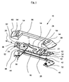
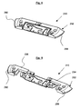
- Fig. 1 and 5 show a strike plate 10 which can be installed in a window or a door. It is connected to a fixed frame, not shown, here. It is used with a likewise not shown sash and an attached espagnolette with associated locking pin for closing the window or the door.
- the striking plate 10 has a first functional area 12 with a slotted guide 14 and a first entry area 16 into which the in Fig. 7 illustrated Locking pin 18 is retractable.
- the slide guide 14 extends substantially in the longitudinal direction 20 of the strike plate 10.
- the strike plate 10 further has a second functional region 22, which is provided with an adjustment channel 24.
- the adjusting channel 24 has a second inlet region 26, in which a in Fig. 7 illustrated Justierzapfen 28 is retractable.
- the striking plate 10 has a third functional area 30, which is connectable to the window frame of the window or the door and has a base element 32.
- a fourth functional region 34 is provided with adjusting means which allow an adjusting movement in the longitudinal direction of the striking plate 10 of the first and second functional regions 12, 22 with respect to the base element 32.
- the adjusting means consist of each frontally to the strike plate 10 arranged guide tabs 36, 38 and present on the base member 32 guide webs 40, 42, 44, 46. By this combination of guide webs mounted between each two guide tabs is aligned in the longitudinal direction 20 of the striker plate 10 adjustment movement the strike plate possible.
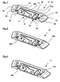
- Fig. 2, 3 and 4 show a strike plate 10 after Fig. 1 , wherein the adjustment movement is present in different deflected states.
- Fig. 2 shows the neutral, central state, recognizable by the equally large Justierspalte 48a, 50a.
- Fig. 3 is shown fully flattened JustierPark, recognizable by the practically reduced to the distance 0 adjustment 48b and twice as large as previously pronounced adjustment gap 50b.
- Fig. 4 is one of the Fig. 3 opposite deflection visible, recognizable also by the Justierspalte 48c, 50c.
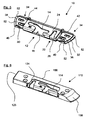
- the guide tabs 36, 38 also have slots 52, can be passed through the screws, not shown, and can be connected to the frame. The screws are thereby pushed by the user through the screw holes 54 and screwed through them in their predetermined direction in the frame and thus fixed in position. The elongated holes 52 now allow a mobility of the guide tabs 36, 38 relative to the screws.
- the striking plate 10 is covered by a cover 56 that is made in one piece and at both end faces in each case a ramp 30, 60 has. These ramps 58, 60 serve to lift the sash in the event that it is sagged against its original position and would otherwise hit against a side edge of the striker plate 10.
- Fig. 6 shows an alternative embodiment of the striker 110.
- the basic functionality is consistent with that in the Fig. 1 to 5 Lock plate 10 shown match, only the orientation of the Justierkanals 124 against the slide guide 114 is reversed reversed.
- the cover member 156 has only a ramp 158, the opposite end face has a cuboid shape whose side surface 125 can serve as a stop surface on a frame leg.
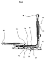
- Fig. 7 shows a strike plate 10 according to the embodiment of Fig. 1 to 5 This is shown spatially with respect to a portion of the espagnolette fitting, in this case a corner drive 62. It is clearly visible as the locking pin 18 in the slide guide 14 is retracted. In addition, it can be seen that the adjusting pin 28 is immersed in the adjusting channel 24. The espagnolette fitting or the corner deflection thereby has a fixed forend area 64 and a longitudinally movable drive rod 66. The locking pin 18 is therefore connected to the drive rod 66 and thus movable along the longitudinal axis 20 of the striking plate in the closed window position. The adjusting pin 28, however, is connected to the forend area 64 and thus fixed relative to this. The adjusting pin therefore serves to adjust the first and second functional region 12, 22 with respect to the espagnolette fitting, independently of the deflection of the drive rod 66.
- FIG. 8 and 9 show an alternative embodiment of the strike plate 210.
- the basic functionality is also in line with the in the Fig. 1 to 5 and 7 Lock plate 10 shown match.
- the difference consists in the design of the base member 232. This is made in two parts with a first base member portion 234 and a second base member portion 236. At this base member 232, the ramps 258, 260 formed directly, and it already has approximately the contour of the Fig. 1 to 5 This function integration further reduces the number of components to be handled for mounting the individual striking plate components.
- Fig. 10 shows an exploded view accordingly Fig. 1 , wherein in addition to the components already described, a cap 68 is placed. This cap ensures a uniform surface design and can also improve the casserole properties.
Landscapes
- Engineering & Computer Science (AREA)
- Mechanical Engineering (AREA)
- Lock And Its Accessories (AREA)
- Specific Sealing Or Ventilating Devices For Doors And Windows (AREA)
- Securing Of Glass Panes Or The Like (AREA)
- Window Of Vehicle (AREA)
Abstract
Description
Die Erfindung betrifft ein Schließblech für ein Fenster oder eine Tür, mit einem ersten Funktionsbereich, der eine Kulissenführung sowie einen ersten Eintrittsbereich für einen Schließbolzen eines Treibstangenbeschlages aufweist, wobei die Kulissenführung im wesentlichen in Längsrichtung des Schließblechs verläuft, mit einem zweiten Funktionsbereich, der einen Justierkanal mit einem zweiten Eintrittsbereich für einen Justierzapfen aufweist, wobei der Justierkanal im wesentlichen senkrecht zu Längsrichtung des Schließblechs verläuft, mit einem dritten Funktionsbereich, der zur Verbindung des Schließblechs mit einem Blendrahmen des Fensters oder der Tür ein Basiselement aufweist, und mit einem vierten Funktionsbereich, der Justiermittel aufweist, die eine Justierbewegung des ersten und zweiten Funktionsbereichs gegenüber dem Basiselement ermöglichen, wobei die Justierbewegung in Längsrichtung des Schließblechs erfolgen kann.The invention relates to a striking plate for a window or a door, having a first functional region, which has a slotted guide and a first entry region for a locking pin of an espagnolette fitting, wherein the sliding guide extends substantially in the longitudinal direction of the striking plate, with a second functional region having an adjustment channel with a second entry region for an alignment pin, wherein the alignment channel extends substantially perpendicular to the longitudinal direction of the strike plate, with a third functional area, which has a base element for connecting the strike plate with a window or door frame, and with a fourth functional area, the Adjusting means which allow an adjustment movement of the first and second functional region relative to the base member, wherein the adjusting movement can take place in the longitudinal direction of the striking plate.
In der
Nachteilig an einem solchen Schließblech ist, dass durch die Ausgestaltung der Führungsbolzen und der Langlöcher sowohl die Herstellung als auch die Montage vergleichsweise aufwendig ist.A disadvantage of such a strike plate is that both the manufacture and the assembly is relatively expensive due to the design of the guide pin and the slots.
Aus der
Der Erfindung liegt die Aufgabe zugrunde, ein Schließblech der eingangs genannten Art derart weiterzubilden, dass die Herstellbarkeit und die Montage vereinfacht wird, ohne dass sich dieses nachteilig auf die Justiermöglichkeit in Längsrichtung auswirkt.The invention has the object of developing a strike plate of the type mentioned in such a way that the manufacturability and assembly is simplified without this adversely affects the adjustment possibility in the longitudinal direction.
Zur Lösung dieser Aufgabe ist vorgesehen, dass die Justiermittel durch zwei jeweils stirnseitig mit dem ersten und zweiten Funktionsbereich einstückig verbundene Führungslappen sowie damit korrespondierend ausgeführten, mit dem Basiselement einstückig verbundenen Führungsstegen gebildet sind, wobei jeweils ein Führungslappen von zwei Führungsstegen umschlossen ist. Damit ist eine fertigungstechnische Vereinfachung erzielt, denn die Fertigung der geometrisch einfach gestalteten Führungslappen und der ebenfalls geometrisch einfach ausgeführten Führungsstege ist deutlich kostengünstiger und vereinfacht gegenüber einer Bolzen-Langloch-Lösung. Zudem wird der Montagevorgang der Einzelkomponenten des Schließblechs zu einer Schließblech-Einheit im Rahmen der Herstellung des Schließblechs vereinfacht, da die einzelnen Komponenten durch einfache lineare Bewegungen zusammensetzbar sind und keine Vernietung, wie dies beim Bolzen erforderlich war, mehr nötig ist. Ein weiterer Vorteil ist, dass die in Kontakt stehenden Flächen durch die breiten Führungslappen vergrößert sind und damit die Kräfte besser verteilt werden können. Zudem wird die Führung durch die langgestreckten Führungsstege verbessert und stabilisiert.To achieve this object, it is provided that the adjusting means are formed by two guide lugs, which are integrally connected to the first and second functional regions and correspondingly configured, with the base member integrally connected guide webs, wherein in each case a guide tab is enclosed by two guide webs. For a manufacturing simplification is achieved, because the production of geometrically simple designed guide tabs and also geometrically simple running guide bars is much cheaper and easier compared to a bolt slot solution. In addition, the assembly process of the individual components of the striking plate is simplified to a striking plate unit in the production of the striking plate, since the individual components are assembled by simple linear movements and no riveting, as was required in the bolt, is more necessary. Another advantage is that the surfaces in contact are enlarged by the wide guide tabs and thus the forces can be better distributed. In addition, the leadership of the elongated guide webs improved and stabilized.
In Weiterbildung der Erfindung ist gemäß Anspruch 2 vorgesehen, dass die Führungslappen in Längsrichtung des Schließblechs ausgerichtete Langlöcher zum Durchtritt von Fixierungsmitteln aufweisen. Diese Langlöcher gewährleisten eine Beweglichkeit des ersten und zweiten Funktionsbereichs gegenüber der Grundplatte, und es ist möglich, die Verschraubungspunkte zur Verbindung des Schließblechs mit dem Blendrahmen in einen bezüglich der Kraftaufnahme günstigen Bereich zu legen, ohne damit die Justierbeweglichkeit einzuschränken.In a further development of the invention is provided according to claim 2, that the guide lugs in the longitudinal direction of the closing plate aligned slots for the passage of fixing means. These slots ensure a mobility of the first and second functional area relative to the base plate, and it is possible to put the screwing points for connecting the striking plate with the frame in a favorable force-receiving area, without limiting the Justierbeweglichkeit.
In weiterer Ausgestaltung der Erfindung ist gemäß Anspruch 3 vorgesehen, dass das Schließblech durch ein einstückig ausgeführtes Abdeckelement überdeckt ist, das an wenigstens einer Stirnseite eine Auflaufschräge aufweist. Die Auflaufschräge hat dabei die Funktion, einen möglicherweise abgesackten Flügelrahmen auf die zum Einschwenken in die Blendrahmenebene erforderliche Höhe anzuheben. Zudem werden durch das Abdeckelement fest definierte Verschraubungspunkte und auch -Richtungen gebildet, die die spätere Montage des Schließblechs am Blendrahmen vereinfachen.In a further embodiment of the invention, it is provided according to claim 3, that the strike plate is covered by an integrally designed cover member having a bevel on at least one end face. The ramp has the function to raise a possibly sagged casement to the height required for pivoting in the frame level. In addition, firmly defined Verschraubungspunkte and also -directions are formed by the cover, which simplify the subsequent assembly of the striker plate on the frame.
In Weiterbildung der Erfindung ist gemäß Anspruch 4 vorgesehen, dass das Basiselement einstückig ausgebildet ist. Dadurch wird der Zusammenhalt der einzelnen Komponenten des Schließblechs verbessert.In a further development of the invention is provided according to claim 4, that the base member is integrally formed. As a result, the cohesion of the individual components of the striking plate is improved.
In weiterer Ausgestaltung der Erfindung ist gemäß Anspruch 5 alternativ zu Anspruch 4 vorgesehen, dass das Basiselement aus zwei Basiselement-Teilbereichen besteht, die etwa mittig des Schließblechs verbindbar sind und die stirnseitig wenigstens eine Auflaufschräge aufweisen. Dadurch ergibt sich die Möglichkeit einer Funktionsintegration zwischen dem Basiselement und dem Abdeckelement.In a further embodiment of the invention is provided according to claim 5 as an alternative to claim 4 that the base element consists of two basic element subregions, which are connected approximately centrally of the striker plate and the front side have at least one ramp. This results in the possibility of functional integration between the base member and the cover.
In Weiterbildung der Erfindung ist gemäß Anspruch 6 vorgesehen, dass das Schließblech und das Abdeckelement durch eine einstückig ausgeführte Abdeckkappe bedeckbar ist, wobei die Kontur der Abdeckkappe im wesentlichen korrespondierend mit der Kontur des Abdeckelements ist. Dadurch kommt es einerseits zu einer einheitlichen Oberflächengestaltung des Schließblechs, anderseits kann die Kontur der Auflaufschräge optimiert werden.In a further development of the invention is provided according to claim 6, that the strike plate and the cover is covered by an integrally running cap, wherein the contour of the cap is substantially corresponding to the contour of the cover. On the one hand, this results in a uniform surface design of the striking plate, on the other hand, the contour of the ramp can be optimized.
In weiterer Ausgestaltung der Erfindung ist gemäß Anspruch 7 und 8 vorgesehen, dass die Kulissenführung einen Ebenenversatz bezogen auf die jeweiligen Endpositionen der Schließbolzen aufweist, der nach Art einer Kröpfung ausgeführt ist, wobei die Kulissenführung vier Funktionsbereiche aufweist, die jeweils einer geschlossenen, drehgeöffneten, kippgeöffneten oder parallel abgestellten Fensterposition zuordbar sind. Die Kontur der Kulissenführung ermöglicht damit erst die vier verschiedenen Fensterpositionen, wodurch zusätzlich zu den genannten drei gewöhnlichen Fensterpositionen eine vierte parallel abgestellte Fensterposition gewährleistet ist.In a further embodiment of the invention is provided according to claim 7 and 8, that the slide guide has a plane offset relative to the respective end positions of the locking bolt, which is designed in the manner of a crank, wherein the sliding guide has four functional areas, each a closed, rotationally open, tilt-open or parallel parked window position are assignable. The contour of the slotted guide thus allows only the four different window positions, which in addition to the above-mentioned three ordinary window positions a fourth parallel parked window position is guaranteed.
Anhand der folgenden Ausführungsbeispiele wird die Erfindung näher erläutert. Dabei zeigt:
- Fig. 1
- Eine Explosionsdarstellung eines erfindungsgemäßen Schließblechs;
- Fig. 2
- eine räumliche Darstellung des Schließblechs nach
Fig. 1 mit einer mittigen Justierstellung; - Fig. 3
- ein Schließblech nach
Fig. 2 in einer nach links ausgelenkten Justierstellung; - Fig. 4
- ein Schließblech nach
Fig. 2 in einer nach rechts ausgelenkten Justierstellung; - Fig. 5
- ein teilweise geöffnetes Schließblech nach
Fig. 2 ; - Fig. 6
- ein Schließblech gem.
Fig. 2 mit einer alternativen Außengehäuseform; - Fig. 7
- eine räumliche Darstellung eines Teilbereiches eines Treibstangenbeschlages sowie des erfindungsgemäßen Schließblechs;
- Fig. 8
- eine räumliche Darstellung eines Schließblechs mit einer zweigeteilten Gehäusestruktur;
- Fig. 9
- eine Explosionsdarstellung des Schließblechs nach
Fig. 8 ; - Fig. 10
- eine Explosionsdarstellung nach
Fig. 1 mit einer zusätzlichen Abdeckkappe.
- Fig. 1
- An exploded view of a striking plate according to the invention;
- Fig. 2
- a spatial representation of the strike plate after
Fig. 1 with a central adjustment position; - Fig. 3
- a strike plate after
Fig. 2 in an adjusted to the left adjustment position; - Fig. 4
- a strike plate after
Fig. 2 in a rightwardly deflected adjustment position; - Fig. 5
- a partially opened strike plate after
Fig. 2 ; - Fig. 6
- a strike plate acc.
Fig. 2 with an alternative outer housing shape; - Fig. 7
- a spatial representation of a portion of an espagnolette fitting and the striking plate according to the invention;
- Fig. 8
- a spatial representation of a striking plate with a two-part housing structure;
- Fig. 9
- an exploded view of the striker after
Fig. 8 ; - Fig. 10
- an exploded view after
Fig. 1 with an additional cover.
Das Schließblech 10 besitzt einen ersten Funktionsbereich 12 mit einer Kulissenführung 14 sowie einem ersten Eintrittsbereich 16, in den der in
Das Schließblech 10 verfügt über einen dritten Funktionsbereich 30, der mit dem Blendrahmen des Fensters oder der Tür verbindbar ist und ein Basiselement 32 aufweist. Ein vierter Funktionsbereich 34 ist mit Justiermitteln versehen, die eine Justierbewegung in Längsrichtung des Schließblechs 10 der ersten und zweiten Funktionsbereiche 12, 22 gegenüber dem Basiselement 32 erlauben. Die Justiermittel bestehen dabei aus jeweils stirnseitig zum Schließblech 10 angeordneten Führungslappen 36, 38 sowie aus am Basiselement 32 vorliegenden Führungsstegen 40, 42, 44, 46. Durch diese Kombination aus zwischen jeweils zwei Führungsstegen gelagerten Führungslappen ist eine in Längsrichtung 20 des Schließblechs 10 ausgerichtete Justierbewegung des Schließblechs möglich.The
Die Führungslappen 36, 38 weisen darüber hinaus Langlöcher 52 auf, durch die nicht dargestellte Schrauben hindurch geführt sein können und mit dem Blendrahmen verbunden werden können. Die Schrauben werden dabei vom Anwender durch die Schrauböffnungen 54 geschoben und durch diese in ihrer vorgegebenen Richtung in den Blendrahmen geschraubt und damit lagefest fixiert. Die Langlöcher 52 erlauben nun eine Beweglichkeit der Führungslappen 36, 38 gegenüber den Schrauben.The
Das Schließblech 10 ist durch ein Abdeckelement 56 bedeckt, dass einstückig ausgeführt ist und an beiden Stirnseiten jeweils eine Auflaufschräge 58, 60 aufweist. Diese Auflaufschrägen 58, 60 dienen zum Anheben des Flügelrahmens für den Fall, dass er gegenüber seiner ursprünglichen Position abgesackt ist und ansonsten gegen eine Seitenkante des Schließblechs 10 schlagen würde.The
Claims (8)
- Locking plate for a window or a door, comprising a first functional region (12) which comprises a sliding guide (14) and a first entry region (16) for a locking pin (18) of an espagnolette (62), the connecting guide link (14) extending substantially in the longitudinal direction (20) of the locking plate (10, 110, 210), comprising a second functional region (22) which comprises an adjustment groove (24) comprising a second entry region (26) for an adjustment pin (28), the adjustment groove (24) extending substantially perpendicular to the longitudinal direction (20) of the locking plate (10, 110, 210), comprising a third functional region (30) which comprises a base member (32) for connecting the locking plate (10, 110, 210) to a window or door frame, and comprising a fourth functional region (34) which comprises adjusting means which make possible an adjusting movement of the first and second functional regions (12, 22) relative to the base member (32), it being possible for the adjusting movement to occur in the longitudinal direction (20) of the locking plate (10, 110, 210), characterised in that the adjusting means are formed by two guide tabs (36, 38), integrally connected at the ends to the first and second functional regions (12, 22) respectively, and guide webs (40, 42, 44, 46) integrally connected to the base member (32) and configured so as to correspond to said guide tabs, each guide tab (36, 38) being enclosed by two guide webs (40, 42, 44, 46).
- Locking plate for a window or a door according to claim 1, characterised in that the guide tabs (36, 38) comprise slots (52) aligned in the longitudinal direction of the locking plate (10, 110, 210) for the passage of fixing means.
- Locking plate for a window or a door according to either claim 1 or claim 2, characterised in that the locking plate (10, 110, 210) is covered by a covering member (56) which is formed in one piece and comprises a bevelled ramp (58, 60) on at least one end face.
- Locking plate for a window or a door according to any one of the preceding claims, characterised in that the base member (32) is formed in one piece.
- Locking plate for a window or a door according to any one of claims 1 to 3, characterised in that the base member consists of two base member subregions (234, 236) which can be connected approximately at the centre of the locking plate (210) and comprise at least one bevelled ramp (258, 260) on the end faces thereof.
- Locking plate for a window or a door according to any one of the preceding claims, characterised in that the locking plate (10, 110, 210) and the covering member (56) can be covered by a covering cap (68) formed in one piece, the contour of the covering cap (68) substantially corresponding to the contour of the covering member (56).
- Locking plate for a window or a door according to any one of the preceding claims, characterised in that the connecting guide link (14) has a planar offset relative to the end positions of the respective locking pins (18) and is configured in the manner of a crank.
- Locking plate for a window or a door according to any one of the preceding claims, characterised in that the connecting guide link (14) comprises four functional regions which can respectively be associated with a closed, rotated open, tilted open or parallel window position.
Priority Applications (1)
| Application Number | Priority Date | Filing Date | Title |
|---|---|---|---|
| PL05100376T PL1568833T3 (en) | 2004-02-25 | 2005-01-21 | Striker plate for a window or a door |
Applications Claiming Priority (2)
| Application Number | Priority Date | Filing Date | Title |
|---|---|---|---|
| DE102004009164A DE102004009164A1 (en) | 2004-02-25 | 2004-02-25 | Strike plate for a window or door |
| DE102004009164 | 2004-02-25 |
Publications (3)
| Publication Number | Publication Date |
|---|---|
| EP1568833A2 EP1568833A2 (en) | 2005-08-31 |
| EP1568833A3 EP1568833A3 (en) | 2009-10-14 |
| EP1568833B1 true EP1568833B1 (en) | 2011-03-09 |
Family
ID=34745271
Family Applications (1)
| Application Number | Title | Priority Date | Filing Date |
|---|---|---|---|
| EP05100376A Not-in-force EP1568833B1 (en) | 2004-02-25 | 2005-01-21 | Striker plate for a window or a door |
Country Status (4)
| Country | Link |
|---|---|
| EP (1) | EP1568833B1 (en) |
| AT (1) | ATE501324T1 (en) |
| DE (2) | DE102004009164A1 (en) |
| PL (1) | PL1568833T3 (en) |
Cited By (1)
| Publication number | Priority date | Publication date | Assignee | Title |
|---|---|---|---|---|
| KR102205390B1 (en) | 2013-03-13 | 2021-01-19 | 로토 프란크 아게 | Multi-part locking component, and sliding door |
Families Citing this family (9)
| Publication number | Priority date | Publication date | Assignee | Title |
|---|---|---|---|---|
| GB2436852A (en) * | 2006-04-05 | 2007-10-10 | Heywood Williams Components Lt | Espagnolette striker with locking means |
| GB2448340A (en) * | 2007-04-12 | 2008-10-15 | Avocet Hardware Ltd | A resilient keep arrangement |
| DE102008054713A1 (en) * | 2008-12-16 | 2010-06-17 | Aug. Winkhaus Gmbh & Co. Kg | Striker plate for an espagnolette fitting |
| DE202013101352U1 (en) | 2013-03-27 | 2013-04-29 | Drinkuth Ag | hardware system |
| EP2924210B1 (en) * | 2014-03-26 | 2019-05-08 | Alban Giacomo S.p.A. | Door or window with shutter-like opening, tilt-and turn opening or the like comprising perimeter hardware and a coupling element |
| DE202015006474U1 (en) | 2015-09-18 | 2015-10-08 | Siegenia-Aubi Kg | Espagnolette |
| DE102017213995A1 (en) * | 2017-08-10 | 2019-02-14 | Aug. Winkhaus Gmbh & Co. Kg | Striker plate for an espagnolette fitting |
| DE102019117862A1 (en) * | 2019-07-02 | 2021-01-07 | Maco Technologie Gmbh | Fitting part |
| DE202019106095U1 (en) * | 2019-11-04 | 2019-11-15 | Siegenia-Aubi Kg | Component system for a bolt engagement |
Family Cites Families (6)
| Publication number | Priority date | Publication date | Assignee | Title |
|---|---|---|---|---|
| DE7041474U (en) * | 1971-02-18 | Fa W Weidtmann | Striking plate, for installation in frames made of wood, metal or plastic profiles of a window, door or the like | |
| DE1185948B (en) * | 1958-09-23 | 1965-01-21 | Curt Weinert | Locking device for windows, doors or the like. |
| FR2486577A1 (en) * | 1980-07-11 | 1982-01-15 | Ferco Int Usine Ferrures | LOCKING FERRULE OF A WINDOW SLIDING DOOR, DOOR OR THE LIKE |
| AT371202B (en) * | 1982-01-26 | 1983-06-10 | Mayer & Co Riegel Beschlag | LOCK FOR A WINDOW OR DOOR |
| GB2233025A (en) * | 1989-04-26 | 1991-01-02 | Smith Wallis & Company Limited | Adjustable keeper |
| DE10254537A1 (en) * | 2002-11-21 | 2004-06-03 | Aug. Winkhaus Gmbh & Co. Kg | Window or door |
-
2004
- 2004-02-25 DE DE102004009164A patent/DE102004009164A1/en not_active Withdrawn
-
2005
- 2005-01-21 DE DE502005011063T patent/DE502005011063D1/en active Active
- 2005-01-21 EP EP05100376A patent/EP1568833B1/en not_active Not-in-force
- 2005-01-21 AT AT05100376T patent/ATE501324T1/en active
- 2005-01-21 PL PL05100376T patent/PL1568833T3/en unknown
Cited By (1)
| Publication number | Priority date | Publication date | Assignee | Title |
|---|---|---|---|---|
| KR102205390B1 (en) | 2013-03-13 | 2021-01-19 | 로토 프란크 아게 | Multi-part locking component, and sliding door |
Also Published As
| Publication number | Publication date |
|---|---|
| PL1568833T3 (en) | 2011-08-31 |
| DE502005011063D1 (en) | 2011-04-21 |
| ATE501324T1 (en) | 2011-03-15 |
| DE102004009164A1 (en) | 2005-09-15 |
| EP1568833A2 (en) | 2005-08-31 |
| EP1568833A3 (en) | 2009-10-14 |
Similar Documents
| Publication | Publication Date | Title |
|---|---|---|
| EP1568833B1 (en) | Striker plate for a window or a door | |
| EP1582673B1 (en) | Striker plate for window or French windows | |
| DE102015219472A1 (en) | Longitudinal adjustment device for a vehicle seat | |
| WO2006136241A1 (en) | Electric door opener for glass doors | |
| DE102011011113B4 (en) | Frame system of a particle protection grid | |
| DE3135401A1 (en) | GATE WITH A LOCKING DEVICE | |
| DE3600211C1 (en) | Window and door fittings | |
| EP2078812A2 (en) | Covering element for a glide rail | |
| EP2871312B1 (en) | Ventilation gap assembly for a sliding door or window and sliding door or window | |
| DE2806491C2 (en) | Locking arrangement for locking a vehicle door | |
| DE2507910B2 (en) | Protection against incorrect operation for the operating linkage of a turn-tilt window | |
| EP2454431B1 (en) | Strap for pivotally connecting a leaf to a frame | |
| DE202008015517U1 (en) | Locking strip for a locking system with multiple locking | |
| DE102014226794A1 (en) | Fitting for installation between a wing and a fixed frame of a window, a door or the like and window, door or the like with such a fitting | |
| EP1449988B1 (en) | Catch module for window- and door-fittings | |
| EP3901082B1 (en) | Car door arrangement for an elevator with a mechanical car door lock | |
| DE3215452A1 (en) | Corner deflection for espagnolette fittings of windows, doors or the like | |
| EP3783178B1 (en) | Door | |
| EP4041974B1 (en) | Opening device for a turn-tilt sash of a window or door | |
| DE2457169A1 (en) | Door or window edge lock - has path of motion of connecting rod or locking pin bounded by half path motion directions | |
| EP2025843A2 (en) | Window or door and component set of a locking part for a window or a door | |
| DE9411037U1 (en) | Security door | |
| DE60012064T2 (en) | Espagnolette closures | |
| DE69500536T2 (en) | Locking device for the semi-fixed sash of a window with two sashes | |
| DE2020240B2 (en) | LOCK FOR A TILTING-TILT SASH OF A WINDOW, A DOOR OR DGL. |
Legal Events
| Date | Code | Title | Description |
|---|---|---|---|
| PUAI | Public reference made under article 153(3) epc to a published international application that has entered the european phase |
Free format text: ORIGINAL CODE: 0009012 |
|
| AK | Designated contracting states |
Kind code of ref document: A2 Designated state(s): AT BE BG CH CY CZ DE DK EE ES FI FR GB GR HU IE IS IT LI LT LU MC NL PL PT RO SE SI SK TR |
|
| AX | Request for extension of the european patent |
Extension state: AL BA HR LV MK YU |
|
| PUAL | Search report despatched |
Free format text: ORIGINAL CODE: 0009013 |
|
| AK | Designated contracting states |
Kind code of ref document: A3 Designated state(s): AT BE BG CH CY CZ DE DK EE ES FI FR GB GR HU IE IS IT LI LT LU MC NL PL PT RO SE SI SK TR |
|
| AX | Request for extension of the european patent |
Extension state: AL BA HR LV MK YU |
|
| RIC1 | Information provided on ipc code assigned before grant |
Ipc: E05C 9/18 20060101ALI20090907BHEP Ipc: E05B 15/02 20060101AFI20050625BHEP |
|
| 17P | Request for examination filed |
Effective date: 20091217 |
|
| AKX | Designation fees paid |
Designated state(s): AT BE BG CH CY CZ DE DK EE ES FI FR GB GR HU IE IS IT LI LT LU MC NL PL PT RO SE SI SK TR |
|
| RIC1 | Information provided on ipc code assigned before grant |
Ipc: E05C 9/18 20060101ALI20100712BHEP Ipc: E05B 15/02 20060101AFI20100712BHEP |
|
| GRAP | Despatch of communication of intention to grant a patent |
Free format text: ORIGINAL CODE: EPIDOSNIGR1 |
|
| GRAS | Grant fee paid |
Free format text: ORIGINAL CODE: EPIDOSNIGR3 |
|
| GRAA | (expected) grant |
Free format text: ORIGINAL CODE: 0009210 |
|
| AK | Designated contracting states |
Kind code of ref document: B1 Designated state(s): AT BE BG CH CY CZ DE DK EE ES FI FR GB GR HU IE IS IT LI LT LU MC NL PL PT RO SE SI SK TR |
|
| REG | Reference to a national code |
Ref country code: GB Ref legal event code: FG4D Free format text: NOT ENGLISH |
|
| REG | Reference to a national code |
Ref country code: CH Ref legal event code: EP |
|
| REG | Reference to a national code |
Ref country code: IE Ref legal event code: FG4D Free format text: LANGUAGE OF EP DOCUMENT: GERMAN |
|
| REF | Corresponds to: |
Ref document number: 502005011063 Country of ref document: DE Date of ref document: 20110421 Kind code of ref document: P |
|
| REG | Reference to a national code |
Ref country code: DE Ref legal event code: R096 Ref document number: 502005011063 Country of ref document: DE Effective date: 20110421 |
|
| REG | Reference to a national code |
Ref country code: NL Ref legal event code: VDEP Effective date: 20110309 |
|
| PG25 | Lapsed in a contracting state [announced via postgrant information from national office to epo] |
Ref country code: GR Free format text: LAPSE BECAUSE OF FAILURE TO SUBMIT A TRANSLATION OF THE DESCRIPTION OR TO PAY THE FEE WITHIN THE PRESCRIBED TIME-LIMIT Effective date: 20110610 Ref country code: SE Free format text: LAPSE BECAUSE OF FAILURE TO SUBMIT A TRANSLATION OF THE DESCRIPTION OR TO PAY THE FEE WITHIN THE PRESCRIBED TIME-LIMIT Effective date: 20110309 Ref country code: ES Free format text: LAPSE BECAUSE OF FAILURE TO SUBMIT A TRANSLATION OF THE DESCRIPTION OR TO PAY THE FEE WITHIN THE PRESCRIBED TIME-LIMIT Effective date: 20110620 Ref country code: LT Free format text: LAPSE BECAUSE OF FAILURE TO SUBMIT A TRANSLATION OF THE DESCRIPTION OR TO PAY THE FEE WITHIN THE PRESCRIBED TIME-LIMIT Effective date: 20110309 |
|
| LTIE | Lt: invalidation of european patent or patent extension |
Effective date: 20110309 |
|
| PG25 | Lapsed in a contracting state [announced via postgrant information from national office to epo] |
Ref country code: SI Free format text: LAPSE BECAUSE OF FAILURE TO SUBMIT A TRANSLATION OF THE DESCRIPTION OR TO PAY THE FEE WITHIN THE PRESCRIBED TIME-LIMIT Effective date: 20110309 Ref country code: NL Free format text: LAPSE BECAUSE OF FAILURE TO SUBMIT A TRANSLATION OF THE DESCRIPTION OR TO PAY THE FEE WITHIN THE PRESCRIBED TIME-LIMIT Effective date: 20110309 Ref country code: FI Free format text: LAPSE BECAUSE OF FAILURE TO SUBMIT A TRANSLATION OF THE DESCRIPTION OR TO PAY THE FEE WITHIN THE PRESCRIBED TIME-LIMIT Effective date: 20110309 Ref country code: CY Free format text: LAPSE BECAUSE OF FAILURE TO SUBMIT A TRANSLATION OF THE DESCRIPTION OR TO PAY THE FEE WITHIN THE PRESCRIBED TIME-LIMIT Effective date: 20110309 Ref country code: BG Free format text: LAPSE BECAUSE OF FAILURE TO SUBMIT A TRANSLATION OF THE DESCRIPTION OR TO PAY THE FEE WITHIN THE PRESCRIBED TIME-LIMIT Effective date: 20110609 |
|
| REG | Reference to a national code |
Ref country code: PL Ref legal event code: T3 |
|
| REG | Reference to a national code |
Ref country code: IE Ref legal event code: FD4D |
|
| PG25 | Lapsed in a contracting state [announced via postgrant information from national office to epo] |
Ref country code: PT Free format text: LAPSE BECAUSE OF FAILURE TO SUBMIT A TRANSLATION OF THE DESCRIPTION OR TO PAY THE FEE WITHIN THE PRESCRIBED TIME-LIMIT Effective date: 20110711 Ref country code: EE Free format text: LAPSE BECAUSE OF FAILURE TO SUBMIT A TRANSLATION OF THE DESCRIPTION OR TO PAY THE FEE WITHIN THE PRESCRIBED TIME-LIMIT Effective date: 20110309 Ref country code: IE Free format text: LAPSE BECAUSE OF FAILURE TO SUBMIT A TRANSLATION OF THE DESCRIPTION OR TO PAY THE FEE WITHIN THE PRESCRIBED TIME-LIMIT Effective date: 20110309 |
|
| PG25 | Lapsed in a contracting state [announced via postgrant information from national office to epo] |
Ref country code: IS Free format text: LAPSE BECAUSE OF FAILURE TO SUBMIT A TRANSLATION OF THE DESCRIPTION OR TO PAY THE FEE WITHIN THE PRESCRIBED TIME-LIMIT Effective date: 20110709 Ref country code: CZ Free format text: LAPSE BECAUSE OF FAILURE TO SUBMIT A TRANSLATION OF THE DESCRIPTION OR TO PAY THE FEE WITHIN THE PRESCRIBED TIME-LIMIT Effective date: 20110309 Ref country code: RO Free format text: LAPSE BECAUSE OF FAILURE TO SUBMIT A TRANSLATION OF THE DESCRIPTION OR TO PAY THE FEE WITHIN THE PRESCRIBED TIME-LIMIT Effective date: 20110309 Ref country code: SK Free format text: LAPSE BECAUSE OF FAILURE TO SUBMIT A TRANSLATION OF THE DESCRIPTION OR TO PAY THE FEE WITHIN THE PRESCRIBED TIME-LIMIT Effective date: 20110309 |
|
| PLBE | No opposition filed within time limit |
Free format text: ORIGINAL CODE: 0009261 |
|
| STAA | Information on the status of an ep patent application or granted ep patent |
Free format text: STATUS: NO OPPOSITION FILED WITHIN TIME LIMIT |
|
| 26N | No opposition filed |
Effective date: 20111212 |
|
| PG25 | Lapsed in a contracting state [announced via postgrant information from national office to epo] |
Ref country code: DK Free format text: LAPSE BECAUSE OF FAILURE TO SUBMIT A TRANSLATION OF THE DESCRIPTION OR TO PAY THE FEE WITHIN THE PRESCRIBED TIME-LIMIT Effective date: 20110309 |
|
| REG | Reference to a national code |
Ref country code: DE Ref legal event code: R097 Ref document number: 502005011063 Country of ref document: DE Effective date: 20111212 |
|
| PG25 | Lapsed in a contracting state [announced via postgrant information from national office to epo] |
Ref country code: IT Free format text: LAPSE BECAUSE OF FAILURE TO SUBMIT A TRANSLATION OF THE DESCRIPTION OR TO PAY THE FEE WITHIN THE PRESCRIBED TIME-LIMIT Effective date: 20110309 |
|
| PGFP | Annual fee paid to national office [announced via postgrant information from national office to epo] |
Ref country code: TR Payment date: 20120123 Year of fee payment: 8 |
|
| BERE | Be: lapsed |
Owner name: AUG. WINKHAUS G.M.B.H. & CO. KG Effective date: 20120131 |
|
| PG25 | Lapsed in a contracting state [announced via postgrant information from national office to epo] |
Ref country code: MC Free format text: LAPSE BECAUSE OF NON-PAYMENT OF DUE FEES Effective date: 20120131 |
|
| REG | Reference to a national code |
Ref country code: CH Ref legal event code: PL |
|
| GBPC | Gb: european patent ceased through non-payment of renewal fee |
Effective date: 20120121 |
|
| PG25 | Lapsed in a contracting state [announced via postgrant information from national office to epo] |
Ref country code: LI Free format text: LAPSE BECAUSE OF NON-PAYMENT OF DUE FEES Effective date: 20120131 Ref country code: GB Free format text: LAPSE BECAUSE OF NON-PAYMENT OF DUE FEES Effective date: 20120121 Ref country code: CH Free format text: LAPSE BECAUSE OF NON-PAYMENT OF DUE FEES Effective date: 20120131 |
|
| PG25 | Lapsed in a contracting state [announced via postgrant information from national office to epo] |
Ref country code: BE Free format text: LAPSE BECAUSE OF NON-PAYMENT OF DUE FEES Effective date: 20120131 |
|
| PGFP | Annual fee paid to national office [announced via postgrant information from national office to epo] |
Ref country code: FR Payment date: 20130219 Year of fee payment: 9 |
|
| PGFP | Annual fee paid to national office [announced via postgrant information from national office to epo] |
Ref country code: PL Payment date: 20130103 Year of fee payment: 9 |
|
| PGFP | Annual fee paid to national office [announced via postgrant information from national office to epo] |
Ref country code: AT Payment date: 20130125 Year of fee payment: 9 |
|
| PGFP | Annual fee paid to national office [announced via postgrant information from national office to epo] |
Ref country code: DE Payment date: 20130328 Year of fee payment: 9 |
|
| PG25 | Lapsed in a contracting state [announced via postgrant information from national office to epo] |
Ref country code: LU Free format text: LAPSE BECAUSE OF NON-PAYMENT OF DUE FEES Effective date: 20120121 |
|
| PG25 | Lapsed in a contracting state [announced via postgrant information from national office to epo] |
Ref country code: HU Free format text: LAPSE BECAUSE OF FAILURE TO SUBMIT A TRANSLATION OF THE DESCRIPTION OR TO PAY THE FEE WITHIN THE PRESCRIBED TIME-LIMIT Effective date: 20050121 |
|
| REG | Reference to a national code |
Ref country code: DE Ref legal event code: R119 Ref document number: 502005011063 Country of ref document: DE |
|
| REG | Reference to a national code |
Ref country code: AT Ref legal event code: MM01 Ref document number: 501324 Country of ref document: AT Kind code of ref document: T Effective date: 20140121 |
|
| REG | Reference to a national code |
Ref country code: DE Ref legal event code: R119 Ref document number: 502005011063 Country of ref document: DE Effective date: 20140801 |
|
| PG25 | Lapsed in a contracting state [announced via postgrant information from national office to epo] |
Ref country code: DE Free format text: LAPSE BECAUSE OF NON-PAYMENT OF DUE FEES Effective date: 20140801 |
|
| REG | Reference to a national code |
Ref country code: FR Ref legal event code: ST Effective date: 20140930 |
|
| PG25 | Lapsed in a contracting state [announced via postgrant information from national office to epo] |
Ref country code: AT Free format text: LAPSE BECAUSE OF NON-PAYMENT OF DUE FEES Effective date: 20140121 Ref country code: FR Free format text: LAPSE BECAUSE OF NON-PAYMENT OF DUE FEES Effective date: 20140131 |
|
| REG | Reference to a national code |
Ref country code: PL Ref legal event code: LAPE |
|
| PG25 | Lapsed in a contracting state [announced via postgrant information from national office to epo] |
Ref country code: PL Free format text: LAPSE BECAUSE OF NON-PAYMENT OF DUE FEES Effective date: 20140121 |
|
| PG25 | Lapsed in a contracting state [announced via postgrant information from national office to epo] |
Ref country code: TR Free format text: LAPSE BECAUSE OF NON-PAYMENT OF DUE FEES Effective date: 20140121 |