EP2672048B1 - Door actuator assembly - Google Patents
Door actuator assembly Download PDFInfo
- Publication number
- EP2672048B1 EP2672048B1 EP13002226.2A EP13002226A EP2672048B1 EP 2672048 B1 EP2672048 B1 EP 2672048B1 EP 13002226 A EP13002226 A EP 13002226A EP 2672048 B1 EP2672048 B1 EP 2672048B1
- Authority
- EP
- European Patent Office
- Prior art keywords
- door actuator
- actuator assembly
- arresting
- door
- prolongation
- Prior art date
- Legal status (The legal status is an assumption and is not a legal conclusion. Google has not performed a legal analysis and makes no representation as to the accuracy of the status listed.)
- Active
Links
Images


Classifications
-
- E—FIXED CONSTRUCTIONS
- E05—LOCKS; KEYS; WINDOW OR DOOR FITTINGS; SAFES
- E05F—DEVICES FOR MOVING WINGS INTO OPEN OR CLOSED POSITION; CHECKS FOR WINGS; WING FITTINGS NOT OTHERWISE PROVIDED FOR, CONCERNED WITH THE FUNCTIONING OF THE WING
- E05F3/00—Closers or openers with braking devices, e.g. checks; Construction of pneumatic or liquid braking devices
- E05F3/22—Additional arrangements for closers, e.g. for holding the wing in opened or other position
- E05F3/221—Mechanical power-locks, e.g. for holding the wing open or for free-moving zones
-
- E—FIXED CONSTRUCTIONS
- E05—LOCKS; KEYS; WINDOW OR DOOR FITTINGS; SAFES
- E05F—DEVICES FOR MOVING WINGS INTO OPEN OR CLOSED POSITION; CHECKS FOR WINGS; WING FITTINGS NOT OTHERWISE PROVIDED FOR, CONCERNED WITH THE FUNCTIONING OF THE WING
- E05F15/00—Power-operated mechanisms for wings
- E05F15/60—Power-operated mechanisms for wings using electrical actuators
- E05F15/603—Power-operated mechanisms for wings using electrical actuators using rotary electromotors
- E05F15/611—Power-operated mechanisms for wings using electrical actuators using rotary electromotors for swinging wings
- E05F15/63—Power-operated mechanisms for wings using electrical actuators using rotary electromotors for swinging wings operated by swinging arms
-
- E—FIXED CONSTRUCTIONS
- E05—LOCKS; KEYS; WINDOW OR DOOR FITTINGS; SAFES
- E05F—DEVICES FOR MOVING WINGS INTO OPEN OR CLOSED POSITION; CHECKS FOR WINGS; WING FITTINGS NOT OTHERWISE PROVIDED FOR, CONCERNED WITH THE FUNCTIONING OF THE WING
- E05F3/00—Closers or openers with braking devices, e.g. checks; Construction of pneumatic or liquid braking devices
- E05F3/22—Additional arrangements for closers, e.g. for holding the wing in opened or other position
- E05F2003/228—Arrangements where the end of the closer arm is sliding in a track
-
- E—FIXED CONSTRUCTIONS
- E05—LOCKS; KEYS; WINDOW OR DOOR FITTINGS; SAFES
- E05F—DEVICES FOR MOVING WINGS INTO OPEN OR CLOSED POSITION; CHECKS FOR WINGS; WING FITTINGS NOT OTHERWISE PROVIDED FOR, CONCERNED WITH THE FUNCTIONING OF THE WING
- E05F15/00—Power-operated mechanisms for wings
- E05F15/60—Power-operated mechanisms for wings using electrical actuators
- E05F15/603—Power-operated mechanisms for wings using electrical actuators using rotary electromotors
- E05F15/611—Power-operated mechanisms for wings using electrical actuators using rotary electromotors for swinging wings
- E05F15/63—Power-operated mechanisms for wings using electrical actuators using rotary electromotors for swinging wings operated by swinging arms
- E05F2015/631—Power-operated mechanisms for wings using electrical actuators using rotary electromotors for swinging wings operated by swinging arms the end of the arm sliding in a track; Slider arms therefor
-
- E—FIXED CONSTRUCTIONS
- E05—LOCKS; KEYS; WINDOW OR DOOR FITTINGS; SAFES
- E05Y—INDEXING SCHEME RELATING TO HINGES OR OTHER SUSPENSION DEVICES FOR DOORS, WINDOWS OR WINGS AND DEVICES FOR MOVING WINGS INTO OPEN OR CLOSED POSITION, CHECKS FOR WINGS AND WING FITTINGS NOT OTHERWISE PROVIDED FOR, CONCERNED WITH THE FUNCTIONING OF THE WING
- E05Y2201/00—Constructional elements; Accessories therefore
- E05Y2201/20—Brakes; Disengaging means, e.g. clutches; Holders, e.g. locks; Stops; Accessories therefore
- E05Y2201/218—Holders
-
- E—FIXED CONSTRUCTIONS
- E05—LOCKS; KEYS; WINDOW OR DOOR FITTINGS; SAFES
- E05Y—INDEXING SCHEME RELATING TO HINGES OR OTHER SUSPENSION DEVICES FOR DOORS, WINDOWS OR WINGS AND DEVICES FOR MOVING WINGS INTO OPEN OR CLOSED POSITION, CHECKS FOR WINGS AND WING FITTINGS NOT OTHERWISE PROVIDED FOR, CONCERNED WITH THE FUNCTIONING OF THE WING
- E05Y2201/00—Constructional elements; Accessories therefore
- E05Y2201/60—Suspension or transmission members; Accessories therefore
- E05Y2201/622—Suspension or transmission members elements
- E05Y2201/686—Rods, links
-
- E—FIXED CONSTRUCTIONS
- E05—LOCKS; KEYS; WINDOW OR DOOR FITTINGS; SAFES
- E05Y—INDEXING SCHEME RELATING TO HINGES OR OTHER SUSPENSION DEVICES FOR DOORS, WINDOWS OR WINGS AND DEVICES FOR MOVING WINGS INTO OPEN OR CLOSED POSITION, CHECKS FOR WINGS AND WING FITTINGS NOT OTHERWISE PROVIDED FOR, CONCERNED WITH THE FUNCTIONING OF THE WING
- E05Y2201/00—Constructional elements; Accessories therefore
- E05Y2201/60—Suspension or transmission members; Accessories therefore
- E05Y2201/622—Suspension or transmission members elements
- E05Y2201/708—Sliders
-
- E—FIXED CONSTRUCTIONS
- E05—LOCKS; KEYS; WINDOW OR DOOR FITTINGS; SAFES
- E05Y—INDEXING SCHEME RELATING TO HINGES OR OTHER SUSPENSION DEVICES FOR DOORS, WINDOWS OR WINGS AND DEVICES FOR MOVING WINGS INTO OPEN OR CLOSED POSITION, CHECKS FOR WINGS AND WING FITTINGS NOT OTHERWISE PROVIDED FOR, CONCERNED WITH THE FUNCTIONING OF THE WING
- E05Y2600/00—Mounting or coupling arrangements for elements provided for in this subclass
- E05Y2600/10—Adjustable or movable
- E05Y2600/14—Adjustable or movable with position retaining means
-
- E—FIXED CONSTRUCTIONS
- E05—LOCKS; KEYS; WINDOW OR DOOR FITTINGS; SAFES
- E05Y—INDEXING SCHEME RELATING TO HINGES OR OTHER SUSPENSION DEVICES FOR DOORS, WINDOWS OR WINGS AND DEVICES FOR MOVING WINGS INTO OPEN OR CLOSED POSITION, CHECKS FOR WINGS AND WING FITTINGS NOT OTHERWISE PROVIDED FOR, CONCERNED WITH THE FUNCTIONING OF THE WING
- E05Y2900/00—Application of doors, windows, wings or fittings thereof
- E05Y2900/10—Application of doors, windows, wings or fittings thereof for buildings or parts thereof
- E05Y2900/13—Application of doors, windows, wings or fittings thereof for buildings or parts thereof characterised by the type of wing
- E05Y2900/132—Doors
Definitions
- the present invention relates to a door actuator arrangement for moving and fixing a door leaf.
- Door actuator arrangements generally comprise a door actuator, designed as a door drive, door closer or servo door closer, a guide rail with a movement element (also a slide) guided therein and a lever as a connection between the door actuator and the movement element.
- the door actuator is either fixed to the wall or frame or directly to the door leaf. If the door actuator is located on the door leaf as an example, the force from the output shaft of the door actuator is transmitted to the movement element via the lever.
- the movement element is guided in a linearly movable manner in the guide rail, which is stationary on the wall or frame. In order to fix the door leaf in its position, the movement element is fixed in the guide rail by means of a locking device.
- the door closer or door operator can also be fixed to the wall or frame. In this case the guide rail is attached to the door leaf.
- US 3,711,823 discloses an example of a door operator assembly.
- the guide rail including the locking device and the door actuator should be able to be integrated or retracted into the frame of the door or into the frame of the door leaf. In the closed state of the door leaf should neither the guide rail nor the door operator are visible to the user.
- a door actuator arrangement for moving and fixing a door leaf comprising: a guide rail, a linearly movably guided movement element in the guide rail and a locking element firmly connected to the movement element.
- a locking device is also provided.
- the locking device serves to lock and release the locking element with respect to the guide rail.
- the locking element is preferably designed as a first locking lug.
- the locking device comprises a second locking lug, the two locking lugs being able to be latched in and out of one another.
- the door actuator arrangement comprises a door actuator with an output shaft and a lever which is rotatably connected to the output shaft and rotatably connected to the moving element.
- An extension between the movement element and the locking element is also provided. The extension is chosen so long that in the closed state of the door leaf the output shaft of the door operator is arranged between the moving element and the locking device.
- the extension according to the invention, when the door leaf is closed, it can happen that the lever, which connects the output shaft to the movement element, abuts the locking device and thus a door that is not functional is created.
- the invention provides that between the movement element and an extension of the locking element is arranged.
- This extension is fixed to the moving element and fixed to the locking element, so that the moving element, the extension and the locking element always carry out the same linear movement. Due to the extension, the locking device can be arranged as close as possible to the pivot axis of the door leaf. As a result, in the closed state of the door leaf, the lever finds sufficient space between the locking device and the movement element. The length of the extension is thus chosen so long that in the closed state of the door leaf the output shaft of the door operator is arranged between the moving element and the locking device.
- the extension is releasably and / or non-positively connected to the movement element. Furthermore, the extension can be releasably connected to the locking element in a positive and / or non-positive manner.
- the "detachable connection” means that this connection can be released and closed again by the installer or maintenance personnel without destruction.
- the length of the extension is adjustable. This allows the extension to be adjusted to the desired opening angle at which the door leaf is to lock.
- the adjustability of the extension is realized in particular by a row of holes or an elongated hole or a clamping rail on the extension.
- the extension can be adjusted to various predefined lengths using the row of holes. Using the elongated hole or the clamping rail, the extension can be continuously adjusted.
- all screw connections necessary for changing the length of the extension are accessible in the assembled state of the door actuator arrangement.
- all parts of the extension, the locking element and also the movement element are guided in a linearly movable manner in the guide rail in such a way that they cannot fall out or can be removed perpendicular to the direction of movement.
- the locking device is also arranged in the guide rail and can be moved in a linearly movable manner in the guide rail.
- the locking device is fixed at a certain position in the guide rail during assembly.
- the locking element is guided in a linearly movable manner in the guide rail by means of a slide shoe or slide piece that is independent of the movement element. This ensures reliable guidance of the locking element regardless of the movement element.
- the extension is supported in the guide rail and guided in a linearly movable manner.
- the extension either also has its own sliding shoe or is accommodated in the guide rail by means of sliding wings.
- the locking device has a locking lug rotatably mounted about an axis of rotation and a locking lug loading the locking lug Spring includes.
- the locking element comprises a further locking lug or is itself designed as a locking lug. The two latches can be snapped into and out of each other.
- the guide rail preferably has a mounting surface, the guide rail being attachable to a door leaf, a frame or a wall by means of the mounting surface.
- the rotatable connection between lever and moving element can be rotated about an axis perpendicular to the mounting surface.
- Two spaced side walls of the guide rail are perpendicular to the mounting surface. The entire elements are guided in a linearly movable manner between these two side walls.
- the extension is particularly preferably constructed in three parts.
- a first part is connected to the movement element or is formed integrally with the movement element.
- a second part is connected to the locking element or is formed integrally with the locking element.
- the two parts are connected by a connector.
- the row of holes, the elongated hole or the clamping rail are formed in particular in the connector, so that the distance between the two parts can be adjusted via the connector.
- the connector is in particular received in the guide rail such that it can only be moved linearly, but cannot be removed perpendicularly to the mounting surface.
- the two other parts, which are connected to the movement element or to the locking element are arranged between the connector and the mounting surface, so that these two parts cannot fall out of the guide rail perpendicular to the mounting surface.
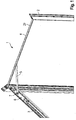
- the door actuator arrangement 1 is integrated into a door frame 2 and a door leaf frame 3.
- the upper horizontal strut of the door frame 2 is shown in FIG Fig. 1 hidden.
- a guide rail 4 is also hidden.
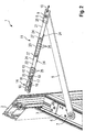
- Fig. 3 shows the underside of the guide rail 4, here the door frame 2 is hidden.
- the door actuator arrangement 1 comprises the door actuator 6, designed as a door closer, which is embedded or integrated in the door leaf frame 3.
- the door actuator 6 has an output shaft 7.
- a lever 5 is also provided. One end of the lever 5 is rotatably connected to the output shaft 7.
- the guide rail 4 is embedded or integrated in the door frame 2.
- the guide rail 4 comprises a mounting surface 29 with mounting holes 30.
- the guide rail 4 is screwed into the door frame 2 via these mounting holes 30.
- the guide rail 4 is open at the bottom.
- the underside of the guide rail 4 shows the Fig. 3 .
- a movement element 8 designed as a slider, is guided so as to be linearly movable along a direction of movement 10.
- An eye 9 is formed in the movement element 8.
- the lever 5 is rotatably connected to the movement element 8 via the eye 9.
- the axis of rotation of the rotatable connection between lever 5 and movement element 8 is perpendicular to the mounting surface 29 and perpendicular to the direction of movement 10.
- a locking element 12 is guided linearly movably in the direction of movement 10 in the guide rail 4.
- the locking element 12 is fixedly connected to the movement element 8 via an extension 11, so that the movement element 8, the extension 11 and the locking element 12 always perform the same linear movement.
- the locking element 12 is seated in its own sliding shoe 13.
- the locking element 12 is guided in the guide rail 4 via this sliding shoe 13.
- a first positive connection 28 is provided for the connection between the fixing element 12 and the sliding shoe 13.
- the extension 11 is composed of a first part 21, a second part 22 and a connector 23 which connects the first part 21 to the second part 22.
- the first part 21 is connected to the movement element 8 via a second positive connection 25.
- the second part 22 is manufactured integrally with the locking element 12.
- the connector 23 is received in the guide rail 4 via sliding vanes 24.
- a row of holes 26 is formed on the connector 23.
- the first part 21 and the second part 22 are each connected to a hole in the row of holes 26 via screw connections 27. As an alternative to the screw connection 27, only bolts can also be used here.
- a locking device 14 is arranged in the guide rail 4.
- the locking device 14 comprises a block 15. This block 15 is fixed in the guide rail 4.
- a rocker arm 17 is rotatably received via an axis of rotation 18.
- the axis of rotation 18 is perpendicular to the mounting surface 29.
- a spiral spring 16 acts on the rocker arm 17.
- a first locking lug 19, designed as a roller, is arranged on the rocker arm 17.
- the two locking lugs 19, 20 can be snapped into and out of each other.
- Fig. 3 shows the maximum lever length 31 for the lever 5.
- the lever 5 In the closed state of the door leaf, the lever 5 must find space between the locking device 14 and the eye 9 on the movement element 8. The length of the extension 11 is set accordingly.
- Fig. 4 shows in detail the slide shoe 13 of the locking element 12.
- two knobs are formed on the slide shoe 13. These two knobs sit positively in two holes on the fixing element 12, so that the first positive connection 28 is formed.
- the slide shoe 13 has a bevel 32, so that the second locking lug 20 can be arranged on the locking element 12 in a space-saving manner.
- FIG. 5 shows the second part 22 of the extension 11. In this exemplary embodiment, the second part 22 is not manufactured integrally with the locking element 12. Furthermore, FIG Fig. 5 the locking element 12 and a simpler slide shoe 13. In Fig. 6 the locking element 12 is hidden to clarify the structure.
- the locking element 12 is connected to the second part 22 of the extension 11 via a further screw connection 35.
- a groove is formed on the second part 22 and on the locking element 12.
- the sliding shoe 13 arranged on one side engages in these grooves to form a third positive connection 33 the sliding block 13 and the second part 22 and a fourth positive connection 34 between the sliding block 13 and the locking element 12.
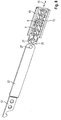
- Fig. 7 shows a detail of the door actuator arrangement 1 according to the third embodiment.
- the guide rail 4 is hidden here for the sake of clarity.
- the fixing element 12 comprises a further sliding piece 36.
- This further sliding piece 36 is constructed in the same way as the moving element 8.
- the moving element 8 and the further sliding piece 36 are shown in FIG Fig. 7 shown transparently.
- the second locking lug 20 is fixedly mounted on the further slide piece 36.
- the second part 22 of the extension 11 is connected to the further slider 36 via the second positive connection 25.
- the same positive connection 25 is thus formed between the first part 21 and the movement element 8 as between the second part 22 and the further slide 36.
- Fig. 8 shows a detail of the door actuator arrangement 1 according to the fourth embodiment. Identical or functionally identical components are provided with the same reference symbols in all exemplary embodiments. Fig. 8 only shows the second part 22 with the locking element 12, the first part 21 and the movement element 8. The remaining components are designed in accordance with the other exemplary embodiments and are not shown for the sake of clarity.
- Fig. 8 is the first part 21 of the extension 11 integrally made with the base body of the moving element 8.
- this common part which represents the first part 21 and the moving element 8 Sliding shoes 13 pushed on both sides, so that this component is slidable in the guide rail 4 according to the direction of movement 10.
- the first part 21 of the extension 11 in contrast to the other exemplary embodiments, can be made much shorter.
- the second part 22 is made longer.
- the screw connection 27 between the first part 21 and the in Fig. 8 Connector 23, not shown, remains fixed at any length of the extension 11.
- the arrangement is adjusted according to Fig. 8 only the screw connection 27 between the second part 22 and the connector 23. This arrangement facilitates assembly and length adjustment, since only one screw has to be opened.
- the shortening of the first part 21 and the extension of the second part 22 is independent of the integral configuration of the movement element 8 and the first part 21.
- the first part 21 can preferably be shortened, so that only the length is adjusted one of the screw connections 27 must be opened.
Description
Vorliegende Erfindung betrifft eine Türbetätigeranordnung zum Bewegen und Festsetzen eines Türflügels.The present invention relates to a door actuator arrangement for moving and fixing a door leaf.
Türbetätigeranordnungen umfassen in der Regel einen Türbetätiger, ausgebildet als Türantrieb, Türschließer oder Servotürschließer, eine Führungsschiene mit einem darin geführten Bewegungselement (auch Gleitstück) und einen Hebel als Verbindung zwischen dem Türbetätiger und dem Bewegungselement. Der Türbetätiger wird entweder ortsfest an der Wand oder Zarge oder direkt am Türflügel befestigt. Befindet sich der Türbetätiger beispielhaft am Türflügel, so wird die Kraft von der Abtriebswelle des Türbetätigers über den Hebel auf das Bewegungselement übertragen. Das Bewegungselement ist dabei in der Führungsschiene, die sich ortsfest an Wand oder Zarge befindet, linear beweglich geführt. Um das Türblatt in seiner Lage zu fixieren, wird das Bewegungselement mittels einer Feststellvorrichtung in der Führungsschiene festgesetzt. Andererseits kann sich der Türschließer oder Türantrieb auch ortsfest an Wand oder Zarge befinden. In diesem Fall wird
die Führungsschiene am Türflügel befestigt.
the guide rail is attached to the door leaf.
Es ist Aufgabe vorliegender Erfindung, eine Türbetätigeranordnung zum Bewegen und Festsetzen eines Türflügels bereitzustellen, die bei kostengünstiger Herstellung und Montage sehr kleinbauend ist. Insbesondere soll die Führungsschiene inklusive Feststellvorrichtung sowie der Türbetätiger in den Rahmen der Tür bzw. in den Rahmen des Türflügels integrierbar bzw. versenkbar sein. Im geschlossenen Zustand des Türflügels soll weder die Führungsschiene noch der Türbetätiger für den Benutzer sichtbar sein.It is an object of the present invention to provide a door actuator arrangement for moving and fixing a door leaf, which is very small in size with inexpensive manufacture and assembly. In particular, the guide rail including the locking device and the door actuator should be able to be integrated or retracted into the frame of the door or into the frame of the door leaf. In the closed state of the door leaf should neither the guide rail nor the door operator are visible to the user.
Die Lösung dieser Aufgabe erfolgt durch die Merkmale des Anspruchs 1. Die Unteransprüche haben bevorzugte Weiterbildungen der Erfindung zum Gegenstand.This object is achieved by the features of claim 1. The subclaims relate to preferred developments of the invention.
Somit wird die Aufgabe gelöst durch eine Türbetätigeranordnung zum Bewegen und Festsetzen eines Türflügels umfassend: eine Führungsschiene, ein in der Führungsschiene linear beweglich geführtes Bewegungselement und ein mit dem Bewegungselement fest verbundenes Feststellelement. Des Weiteren ist eine Feststellvorrichtung vorgesehen. Die Feststellvorrichtung dient zum Feststellen und Freigeben des Feststellelementes gegenüber der Führungsschiene. Bevorzugt ist das Feststellelement als erste Rastnase ausgebildet. In entsprechender Weise umfasst die Feststellvorrichtung eine zweite Rastnase, wobei die beiden Rastnasen aneinander ein- und ausrastbar sind. Darüber hinaus umfasst die Türbetätigeranordnung einen Türbetätiger mit einer Abtriebswelle und einen Hebel, der drehfest mit der Abtriebswelle und drehbar mit dem Bewegungselement verbunden ist. Ferner ist eine Verlängerung zwischen dem Bewegungselement und dem Feststellelement vorgesehen. Die Verlängerung ist so lang gewählt, dass im geschlossenen Zustand des Türflügels die Abtriebswelle des Türbetätigers zwischen dem Bewegungselement und der Feststellvorrichtung angeordnet ist.The object is thus achieved by a door actuator arrangement for moving and fixing a door leaf comprising: a guide rail, a linearly movably guided movement element in the guide rail and a locking element firmly connected to the movement element. A locking device is also provided. The locking device serves to lock and release the locking element with respect to the guide rail. The locking element is preferably designed as a first locking lug. In a corresponding manner, the locking device comprises a second locking lug, the two locking lugs being able to be latched in and out of one another. In addition, the door actuator arrangement comprises a door actuator with an output shaft and a lever which is rotatably connected to the output shaft and rotatably connected to the moving element. An extension between the movement element and the locking element is also provided. The extension is chosen so long that in the closed state of the door leaf the output shaft of the door operator is arranged between the moving element and the locking device.
Ohne der erfindungsgemäßen Verlängerung kann es beim Schließen des Türflügels dazu kommen, dass der Hebel, welcher die Abtriebswelle mit dem Bewegungselement verbindet, an der Feststellvorrichtung anstößt und somit eine funktionsuntüchtige Tür entsteht. Um diese Problematik zu vermeiden, ist erfindungsgemäß vorgesehen, dass zwischen dem Bewegungselement und dem Feststellelement eine Verlängerung angeordnet ist.Without the extension according to the invention, when the door leaf is closed, it can happen that the lever, which connects the output shaft to the movement element, abuts the locking device and thus a door that is not functional is created. In order to avoid this problem, the invention provides that between the movement element and an extension of the locking element is arranged.
Diese Verlängerung ist fest mit dem Bewegungselement und fest mit dem Feststellelement verbunden, so dass das Bewegungselement, die Verlängerung und das Feststellelement stets die gleiche lineare Bewegung ausführen. Aufgrund der Verlängerung kann die Feststellvorrichtung möglichst nahe an der Schwenkachse des Türflügels angeordnet werden. Dadurch findet im geschlossenen Zustand des Türflügels der Hebel ausreichend Platz zwischen der Feststellvorrichtung und dem Bewegungselement. Die Länge der Verlängerung wird also so lang gewählt, dass im geschlossenen Zustand des Türflügels die Abtriebswelle des Türbetätigers zwischen dem Bewegungselement und der Feststellvorrichtung angeordnet ist.This extension is fixed to the moving element and fixed to the locking element, so that the moving element, the extension and the locking element always carry out the same linear movement. Due to the extension, the locking device can be arranged as close as possible to the pivot axis of the door leaf. As a result, in the closed state of the door leaf, the lever finds sufficient space between the locking device and the movement element. The length of the extension is thus chosen so long that in the closed state of the door leaf the output shaft of the door operator is arranged between the moving element and the locking device.
Bevorzugt ist vorgesehen, dass die Verlängerung form- und/oder kraftschlüssig mit dem Bewegungselement lösbar verbunden ist. Des Weiteren kann die Verlängerung form- und/oder kraftschlüssig mit dem Feststellelement lösbar verbunden sein. Die "lösbare Verbindung" bedeutet, dass diese Verbindung durch den Monteur oder ein Wartungspersonal zerstörungsfrei gelöst und wieder geschlossen werden kann.It is preferably provided that the extension is releasably and / or non-positively connected to the movement element. Furthermore, the extension can be releasably connected to the locking element in a positive and / or non-positive manner. The "detachable connection" means that this connection can be released and closed again by the installer or maintenance personnel without destruction.
Erfindungsgemäß ist die Länge der Verlängerung einstellbar ist. Dadurch kann die Verlängerung an den gewünschten Öffnungswinkel, bei dem der Türflügel verrasten soll, angepasst werden.According to the invention, the length of the extension is adjustable. This allows the extension to be adjusted to the desired opening angle at which the door leaf is to lock.
Die Einstellbarkeit der Verlängerung wird insbesondere durch eine Lochreihe oder ein Langloch oder eine Klemmschiene an der Verlängerung realisiert. Mittels der Lochreihe kann die Verlängerung auf verschiedene vordefinierte Längen justiert werden. Mittels dem Langloch oder der Klemmschiene ist eine stufenlose Verstellung der Verlängerung möglich.The adjustability of the extension is realized in particular by a row of holes or an elongated hole or a clamping rail on the extension. The extension can be adjusted to various predefined lengths using the row of holes. Using the elongated hole or the clamping rail, the extension can be continuously adjusted.
Insbesondere ist vorgesehen, dass alle zum Ändern der Länge der Verlängerung notwendigen Verschraubungen im montierten Zustand der Türbetätigeranordnung zugänglich sind. Insbesondere sind alle Teile der Verlängerung, das Feststellelement und auch das Bewegungselement so in der Führungsschiene linear beweglich geführt, dass sie nicht senkrecht zur Bewegungsrichtung herausfallen können oder herausgenommen werden können. Durch Lösen der Verschraubung an der Verlängerung sind somit die Einzelteile der Verlängerung separat verschiebbar, verbleiben jedoch innerhalb der Führungsschiene. Der Monteur kann somit die Länge der Verlängerung justieren und die Verlängerung in der gewünschten Länge wieder fixieren.In particular, it is provided that all screw connections necessary for changing the length of the extension are accessible in the assembled state of the door actuator arrangement. In particular, all parts of the extension, the locking element and also the movement element are guided in a linearly movable manner in the guide rail in such a way that they cannot fall out or can be removed perpendicular to the direction of movement. By loosening the screw connection on the extension, the individual parts of the extension can be moved separately, but remain within the guide rail. The fitter can thus adjust the length of the extension and fix the extension in the desired length again.
In bevorzugter Ausführung ist auch die Feststellvorrichtung in der Führungsschiene angeordnet und in der Führungsschiene linear beweglich verschiebbar. Die Feststellvorrichtung wird bei der Montage an einer bestimmten Position in der Führungsschiene fixiert.In a preferred embodiment, the locking device is also arranged in the guide rail and can be moved in a linearly movable manner in the guide rail. The locking device is fixed at a certain position in the guide rail during assembly.
Des Weiteren ist vorgesehen, dass das Feststellelement mittels eines vom Bewegungselement unabhängigen Gleitschuhs oder Gleitstücks in der Führungsschiene linear beweglich geführt ist. Dadurch wird eine sichere Führung des Feststellelementes unabhängig vom Bewegungselement sichergestellt.Furthermore, it is provided that the locking element is guided in a linearly movable manner in the guide rail by means of a slide shoe or slide piece that is independent of the movement element. This ensures reliable guidance of the locking element regardless of the movement element.
Darüber hinaus ist auch bevorzugt vorgesehen, dass die Verlängerung in der Führungsschiene abgestützt und linear beweglich geführt ist. Hierzu weist die Verlängerung entweder ebenfalls einen eigenen Gleitschuh auf oder ist mittels Gleitflügeln in der Führungsschiene aufgenommen.In addition, it is preferably also provided that the extension is supported in the guide rail and guided in a linearly movable manner. For this purpose, the extension either also has its own sliding shoe or is accommodated in the guide rail by means of sliding wings.
Ferner ist bevorzugt vorgesehen, dass die Feststellvorrichtung eine um eine Drehachse drehbar gelagerte Rastnase und eine die Rastnase belastende Feder umfasst. Das Feststellelement umfasst eine weitere Rastnase oder ist selbst als Rastnase ausgebildet. Die beiden Rastnasen sind aneinander ein- und ausrastbar.Furthermore, it is preferably provided that the locking device has a locking lug rotatably mounted about an axis of rotation and a locking lug loading the locking lug Spring includes. The locking element comprises a further locking lug or is itself designed as a locking lug. The two latches can be snapped into and out of each other.
Die Führungsschiene weist bevorzugt eine Montagefläche auf, wobei die Führungsschiene mittels der Montagefläche an einem Türflügel, einer Zarge oder einer Wand befestigbar ist. Die drehbare Verbindung zwischen Hebel und Bewegungselement ist um eine senkrecht zur Montagefläche stehende Achse drehbar. Senkrecht zur Montagefläche stehen zwei beabstandete Seitenwände der Führungsschiene. Zwischen diesen beiden Seitenwänden sind die gesamten Elemente linear beweglich geführt.The guide rail preferably has a mounting surface, the guide rail being attachable to a door leaf, a frame or a wall by means of the mounting surface. The rotatable connection between lever and moving element can be rotated about an axis perpendicular to the mounting surface. Two spaced side walls of the guide rail are perpendicular to the mounting surface. The entire elements are guided in a linearly movable manner between these two side walls.
Des Weiteren ist bevorzugt vorgesehen, dass zumindest ein Bauteil der Verlängerung derart in der Führungsschiene geführt ist, so dass dieses Bauteil lediglich in Bewegungsrichtung des Bewegungselementes linear beweglich ist und nicht senkrecht zur Montagefläche entnehmbar ist. Besonders bevorzugt ist die Verlängerung dreiteilig aufgebaut. Ein erstes Teil ist mit dem Bewegungselement verbunden oder integral mit dem Bewegungselement ausgebildet. Ein zweites Teil ist mit dem Feststellelement verbunden oder integral mit dem Feststellelement ausgebildet. Die beiden Teile sind über einen Verbinder miteinander verbunden. Insbesondere in dem Verbinder sind die Lochreihe, das Langloch oder die Klemmschiene ausgebildet, so dass der Abstand zwischen den beiden Teilen über den Verbinder einstellbar ist. Der Verbinder ist insbesondere derart in der Führungsschiene aufgenommen, so dass er lediglich linear beweglich ist, aber nicht senkrecht zur Montagefläche entnommen werden kann. Die beiden weiteren Teile, die mit dem Bewegungselement bzw. mit dem Feststellelement verbunden sind, sind zwischen dem Verbinder und der Montagefläche angeordnet, so dass auch diese beiden Teile nicht senkrecht zur Montagefläche aus der Führungsschiene herausfallen können.Furthermore, it is preferably provided that at least one component of the extension is guided in the guide rail such that this component can only be moved linearly in the direction of movement of the movement element and cannot be removed perpendicularly to the mounting surface. The extension is particularly preferably constructed in three parts. A first part is connected to the movement element or is formed integrally with the movement element. A second part is connected to the locking element or is formed integrally with the locking element. The two parts are connected by a connector. The row of holes, the elongated hole or the clamping rail are formed in particular in the connector, so that the distance between the two parts can be adjusted via the connector. The connector is in particular received in the guide rail such that it can only be moved linearly, but cannot be removed perpendicularly to the mounting surface. The two other parts, which are connected to the movement element or to the locking element, are arranged between the connector and the mounting surface, so that these two parts cannot fall out of the guide rail perpendicular to the mounting surface.
Im Folgenden wird die Erfindung anhand von Ausführungsbeispielen genauer erläutert. Dabei zeigen:
- Fig. 1
- eine erfindungsgemäße Türbetätigeranordnung gemäß einem ersten Ausführungsbeispiel,
- Fig. 2
- ein erstes Detail der erfindungsgemäßen Türbetätigeranordnung gemäß dem ersten Ausführungsbeispiel,
- Fig. 3
- ein zweites Detail der erfindungsgemäßen Türbetätigeranordnung gemäß dem ersten Ausführungsbeispiel,
- Fig. 4
- einen Gleitschuh der erfindungsgemäßen Türbetätigeranordnung gemäß dem ersten Ausführungsbeispiel,
- Fig. 5
- ein Detail der erfindungsgemäßen Türbetätigeranordnung gemäß einem zweiten Ausführungsbeispiel,
- Fig. 6
- ein weiteres Detail der erfindungsgemäßen Türbetätigeranordnung gemäß dem zweiten Ausführungsbeispiel,
- Fig. 7
- ein Detail der erfindungsgemäßen Türbetätigeranordnung gemäß einem dritten Ausführungsbeispiel, und
- Fig. 8
- ein Detail der erfindungsgemäßen Türbetätigeranordnung gemäß einem vierten Ausführungsbeispiel.
- Fig. 1
- an inventive door actuator arrangement according to a first embodiment,
- Fig. 2
- a first detail of the door actuator arrangement according to the invention according to the first embodiment,
- Fig. 3
- 2 shows a second detail of the door actuator arrangement according to the invention in accordance with the first exemplary embodiment,
- Fig. 4
- a sliding block of the door actuator arrangement according to the invention according to the first embodiment,
- Fig. 5
- 2 shows a detail of the door actuator arrangement according to the invention in accordance with a second exemplary embodiment,
- Fig. 6
- another detail of the door actuator arrangement according to the invention according to the second embodiment,
- Fig. 7
- a detail of the door actuator arrangement according to the invention according to a third embodiment, and
- Fig. 8
- a detail of the door actuator arrangement according to the invention according to a fourth embodiment.
Anhand der
Die Türbetätigeranordnung 1 wird integriert in einen Türrahmen 2 und einen Türflügelrahmen 3. Die obere horizontale Strebe des Türrahmens 2 ist der Übersichtlichkeit halber in
Die Türbetätigeranordnung 1 umfasst den Türbetätiger 6, ausgebildet als Türschließer, der in den Türflügelrahmen 3 eingelassen bzw. integriert ist. Der Türbetätiger 6 weist eine Abtriebswelle 7 auf. Des Weiteren ist ein Hebel 5 vorgesehen. Ein Ende des Hebels 5 ist drehfest mit der Abtriebswelle 7 verbunden.The door actuator arrangement 1 comprises the door actuator 6, designed as a door closer, which is embedded or integrated in the
In den Türrahmen 2 ist die Führungsschiene 4 eingelassen bzw. integriert. Die Führungsschiene 4 umfasst eine Montagefläche 29 mit Montagelöchern 30. Über diese Montagelöcher 30 wird die Führungsschiene 4 in dem Türrahmen 2 verschraubt. Die Führungsschiene 4 ist nach unten hin offen. Die Unterseite der Führungsschiene 4 zeigt die
In der Führungsschiene 4 ist ein Bewegungselement 8, ausgebildet als Gleitstück, entlang einer Bewegungsrichtung 10 linear beweglich geführt. In dem Bewegungselement 8 ist ein Auge 9 ausgebildet. Der Hebel 5 ist drehbar über das Auge 9 mit dem Bewegungselement 8 verbunden. Die Drehachse der drehbaren Verbindung zwischen Hebel 5 und Bewegungselement 8 steht senkrecht auf der Montagefläche 29 und senkrecht auf der Bewegungsrichtung 10.In the guide rail 4, a
Des Weiteren ist in der Führungsschiene 4 ein Feststellelement 12 in Bewegungsrichtung 10 linear beweglich geführt. Das Feststellelement 12 ist über eine Verlängerung 11 fest mit dem Bewegungselement 8 verbunden, so dass das Bewegungselement 8, die Verlängerung 11 und das Feststellelement 12 stets die gleiche lineare Bewegung ausführen. Das Feststellelement 12 sitzt in einem eigenen Gleitschuh 13. Über diesen Gleitschuh 13 ist das Feststellelement 12 in der Führungsschiene 4 geführt. Zur Verbindung zwischen Feststellelement 12 und Gleitschuh 13 ist eine erste formschlüssige Verbindung 28 vorgesehen.Furthermore, a locking
Die Verlängerung 11 setzt sich zusammen aus einem ersten Teil 21, einem zweiten Teil 22 und einem Verbinder 23, der das erste Teil 21 mit dem zweiten Teil 22 verbindet. Das erste Teil 21 ist über eine zweite formschlüssige Verbindung 25 mit dem Bewegungselement 8 verbunden. Das zweite Teil 22 ist integral gefertigt mit dem Feststellelement 12. Der Verbinder 23 ist über Gleitflügel 24 in der Führungsschiene 4 aufgenommen. Des Weiteren ist am Verbinder 23 eine Lochreihe 26 ausgebildet. Über Schraubverbindungen 27 sind das erste Teil 21 und das zweite Teil 22 jeweils mit einem Loch der Lochreihe 26 verbunden. Alternativ zur Verschraubung 27 können hier auch nur Bolzen verwendet werden.The
In der Führungsschiene 4 ist eine Feststellvorrichtung 14 angeordnet. Die Feststellvorrichtung 14 umfasst einen Block 15. Dieser Block 15 ist in der Führungsschiene 4 fixiert. In dem Block 15 ist ein Kipphebel 17 über eine Drehachse 18 drehbeweglich aufgenommen. Die Drehachse 18 steht senkrecht auf der Montagefläche 29. Dadurch verschwenkt der Kipphebel 17 in einer Ebene parallel zur Montagefläche 29. Auf den Kipphebel 17 wirkt eine Spiralfeder 16. Am Kipphebel 17 ist eine erste Rastnase 19, ausgebildet als Rolle, angeordnet. Zur ersten Rastnase 19 gibt es eine komplementäre zweite Rastnase 20 am Feststellelement 12. Die beiden Rastnase 19, 20 sind aneinander ein- und ausrastbar. Beim Ein- und Ausrasten verschwenkt der Kipphebel 17 entgegen der Kraft der Feder 16.A locking
Anhand der
Im zweiten Ausführungsbeispiel ist das Feststellelement 12 über eine weitere Verschraubung 35 mit dem zweiten Teil 22 der Verlängerung 11 verbunden. Am zweiten Teil 22 und am Feststellelement 12 ist jeweils eine Nut ausgebildet. In diese Nuten greift der einseitig angeordnete Gleitschuh 13 zur Ausbildung einer dritten formschlüssigen Verbindung 33 zwischen dem Gleitschuh 13 und dem zweiten Teil 22 und einer vierten formschlüssigen Verbindung 34 zwischen dem Gleitschuh 13 und dem Feststellelement 12.In the second exemplary embodiment, the locking
Im dritten Ausführungsbeispiel umfasst das Feststellelement 12 ein weiteres Gleitstück 36. Dieses weitere Gleitstück 36 ist baugleich ausgebildet mit dem Bewegungselement 8. Zur Verdeutlichung des Aufbaus sind das Bewegungselement 8 und das weitere Gleitstück 36 in
Gemäß
Des Weiteren zeigt
- 11
- TürbetätigeranordnungDoor actuator arrangement
- 22nd
- TürrahmenDoor frame
- 33rd
- TürflügelrahmenLeaf frame
- 44th
- FührungsschieneGuide rail
- 55
- Hebellever
- 66
- TürbetätigerDoor operator
- 77
- AbtriebswelleOutput shaft
- 88th
- BewegungselementMovement element
- 99
- Augeeye
- 1010th
- BewegungsrichtungDirection of movement
- 1111
- Verlängerungrenewal
- 1212th
- FeststellelementLocking element
- 1313
- GleitschuhSliding shoe
- 1414
- FeststellvorrichtungLocking device
- 1515
- Blockblock
- 1616
- Federfeather
- 1717th
- Kipphebelrocker arm
- 1818th
- DrehachseAxis of rotation
- 1919th
- erste Rastnasefirst latch
- 2020th
- zweite Rastnasesecond latch
- 2121st
- erstes Teilfirst part
- 2222
- zweites Teilsecond part
- 2323
- VerbinderInterconnects
- 2424th
- GleitflügelSliding wing
- 2525th
- zweite formschlüssige Verbindungsecond positive connection
- 2626
- LochreiheRow of holes
- 2727th
- VerschraubungScrew connection
- 2929
- MontageflächeMounting surface
- 3030th
- MontagelöcherMounting holes
- 3131
- maximale Hebellängemaximum lever length
- 3232
- Abschrägungbevel
- 33, 3433, 34
- formschlüssige Verbindungenpositive connections
- 3535
- weitere Verschraubungfurther screw connection
- 3636
- weiteres Gleitstückanother slider
Claims (10)
- A door actuator assembly (1) for moving and for arresting a door leaf, comprising:- a guiding rail (4),- a element of motion (8) linearly mobile guided in the guiding rail (4),- an arresting element (12) firmly connected to the element of motion (8),- an arresting device (14) for arresting and releasing the arresting element (12) with regard to the guiding rail (4),- a door actuator (6) having an output shaft (7),- a lever (7), which is connected torque-proof to the output shaft (5) and rotatably to the element of motion (8),characterized in that a prolongation (11) is disposed between the element of motion (8) and the arresting element (12), which prolongation is firmly connected to the element of motion (8) and firmly to the arresting element (12), wherein the prolongation (11) is so long that, in the closed condition of the door leaf (2), the output shaft (7) of the door actuator (6) is disposed between the element of motion (8) and the arresting device (14),
wherein the length of the prolongation (11) is adjustable. - The door actuator assembly according to claim 1, characterized in that the prolongation (11) is positively and/or non-positively releasably connected to the element of motion (8), and/or in that the prolongation (11) is positively and/or non-positively connected releasably to the arresting element (12).
- The door actuator assembly according to claim 1, characterized in that the prolongation (11) includes a row of holes (26) or an oblong hole or a clamping rail for adjusting the length.
- The door actuator assembly according to any of the claims 1 or 3, characterized in that all screw connections (27) necessary for modifying the length of the prolongation (11) are accessible in the mounted condition of the door actuator assembly (1).
- The door actuator assembly according to any of the preceding claims, characterized in that the arresting device (14) is disposed in the guiding rail (4).
- The door actuator assembly according to any of the preceding claims, characterized in that the arresting element (12) is linearly mobile guided in the guiding rail (4) by means of a sliding shoe (13) or a sliding member (36), which is independent of the element of motion (8).
- The door actuator assembly according to any of the preceding claims, characterized in that the prolongation (11) is supported and linearly mobile guided in the guiding rail (4).
- The door actuator assembly according to any of the preceding claims, characterized in that the arresting device (14) comprises a first latching nose (19), which is rotatably supported about an axis of rotation (18), and a spring (16) charging the first latching nose (19), and in that the arresting element (12) comprises a second latching nose (20), wherein the first and the second latching noses (19, 20) are latchable and unlatchable to each other.
- The door actuator assembly according to any of the preceding claims, characterized in that the guiding rail (4) includes a mounting surface (29), wherein the guiding rail (4) is attachable to a door leaf, to a casing or to a wall by means of the mounting surface (29), and wherein the rotatable connection between lever (5) and element of motion (8) is rotatable about an axis, which is vertical to the mounting surface (29).
- The door actuator assembly according to claim 9, characterized in that at least one component (23) of the prolongation (11) is guided such in the guiding rail (4) that said component (23) is just linearly mobile in the direction of movement (10) of the element of motion (8) and cannot be removed vertically to the mounting surface (29).
Applications Claiming Priority (1)
| Application Number | Priority Date | Filing Date | Title |
|---|---|---|---|
| DE102012104864A DE102012104864A1 (en) | 2012-06-05 | 2012-06-05 | Türbetätigeranordnung |
Publications (3)
| Publication Number | Publication Date |
|---|---|
| EP2672048A2 EP2672048A2 (en) | 2013-12-11 |
| EP2672048A3 EP2672048A3 (en) | 2017-11-01 |
| EP2672048B1 true EP2672048B1 (en) | 2020-06-03 |
Family
ID=48190067
Family Applications (1)
| Application Number | Title | Priority Date | Filing Date |
|---|---|---|---|
| EP13002226.2A Active EP2672048B1 (en) | 2012-06-05 | 2013-04-26 | Door actuator assembly |
Country Status (2)
| Country | Link |
|---|---|
| EP (1) | EP2672048B1 (en) |
| DE (1) | DE102012104864A1 (en) |
Families Citing this family (1)
| Publication number | Priority date | Publication date | Assignee | Title |
|---|---|---|---|---|
| CN104695817B (en) * | 2015-02-16 | 2016-06-01 | 广西南宁市繁星科技有限公司 | A kind of automatic multiple leaf door with unidirectional ratchet Xian Qi mechanism |
Family Cites Families (2)
| Publication number | Priority date | Publication date | Assignee | Title |
|---|---|---|---|---|
| US3771823A (en) * | 1972-02-24 | 1973-11-13 | Schlage Lock Co | Electrically controlled hold-open device |
| DE9303973U1 (en) * | 1993-03-18 | 1994-07-14 | Gretsch Unitas Gmbh | Door closer |
-
2012
- 2012-06-05 DE DE102012104864A patent/DE102012104864A1/en not_active Withdrawn
-
2013
- 2013-04-26 EP EP13002226.2A patent/EP2672048B1/en active Active
Non-Patent Citations (1)
| Title |
|---|
| None * |
Also Published As
| Publication number | Publication date |
|---|---|
| EP2672048A3 (en) | 2017-11-01 |
| EP2672048A2 (en) | 2013-12-11 |
| DE102012104864A1 (en) | 2013-12-05 |
Similar Documents
| Publication | Publication Date | Title |
|---|---|---|
| EP3039212B1 (en) | Actuator for movable furniture parts | |
| EP3556976A1 (en) | Device for moving a piece of furniture on a body of a piece of furniture | |
| EP2397634B1 (en) | Method for installing a device for spring assisted pivoting of a flap or door in a vehicle | |
| EP3088646A1 (en) | Guide device for a sliding door | |
| EP3251554A1 (en) | Joining device for joining a table leg to a tabletop | |
| EP2430273B1 (en) | Furniture flap drive that can be swiveled open | |
| DE202012002502U1 (en) | Device for assisting and facilitating the tilting opening and closing of a window or a door | |
| AT511587B1 (en) | MOVABLE MOUNTING PLATE FOR FURNITURE HINGES | |
| EP3625415B1 (en) | Flap bearing with an adjustment aid | |
| EP3175068A1 (en) | Fitting arrangement | |
| EP2672048B1 (en) | Door actuator assembly | |
| EP2672041A2 (en) | Guide rail assembly | |
| EP2078812A2 (en) | Covering element for a glide rail | |
| DE102012104851A1 (en) | Track assembly | |
| EP3498941A1 (en) | Actuating handle with blocking device | |
| EP3967840B1 (en) | Actuator | |
| DE102012104852A1 (en) | Track assembly | |
| EP3183408B1 (en) | Control element for a fitting arrangement | |
| DE102013212651B3 (en) | Device for controlling the closing sequence of a two-leaf revolving door system | |
| EP2341206A2 (en) | Corner bearing of the wing of a window pivotable against a frame and window with such a corner bearing | |
| EP2942463A1 (en) | Adjustable fitting - in particular hinge for a door leaf | |
| EP3327228B1 (en) | Locking device for locking and transport of at least two mounted plate-shaped elements which can be moved along a first direction and an opposing second direction and wall assembly with at least two panel-shaped elements | |
| EP2949848A1 (en) | Device for moving a folding flap that moves on a furniture body and piece of furniture with such a device | |
| DE202012010979U1 (en) | Pushrod closure | |
| EP2740872A2 (en) | Corner bearing for concealed assembly |
Legal Events
| Date | Code | Title | Description |
|---|---|---|---|
| PUAI | Public reference made under article 153(3) epc to a published international application that has entered the european phase |
Free format text: ORIGINAL CODE: 0009012 |
|
| AK | Designated contracting states |
Kind code of ref document: A2 Designated state(s): AL AT BE BG CH CY CZ DE DK EE ES FI FR GB GR HR HU IE IS IT LI LT LU LV MC MK MT NL NO PL PT RO RS SE SI SK SM TR |
|
| AX | Request for extension of the european patent |
Extension state: BA ME |
|
| RAP1 | Party data changed (applicant data changed or rights of an application transferred) |
Owner name: DORMA DEUTSCHLAND GMBH |
|
| RAP1 | Party data changed (applicant data changed or rights of an application transferred) |
Owner name: DORMAKABA DEUTSCHLAND GMBH |
|
| PUAL | Search report despatched |
Free format text: ORIGINAL CODE: 0009013 |
|
| AK | Designated contracting states |
Kind code of ref document: A3 Designated state(s): AL AT BE BG CH CY CZ DE DK EE ES FI FR GB GR HR HU IE IS IT LI LT LU LV MC MK MT NL NO PL PT RO RS SE SI SK SM TR |
|
| AX | Request for extension of the european patent |
Extension state: BA ME |
|
| RIC1 | Information provided on ipc code assigned before grant |
Ipc: E05F 15/12 00000000AFI20170925BHEP Ipc: E05F 3/22 20060101ALI20170925BHEP |
|
| STAA | Information on the status of an ep patent application or granted ep patent |
Free format text: STATUS: REQUEST FOR EXAMINATION WAS MADE |
|
| 17P | Request for examination filed |
Effective date: 20180315 |
|
| RBV | Designated contracting states (corrected) |
Designated state(s): AL AT BE BG CH CY CZ DE DK EE ES FI FR GB GR HR HU IE IS IT LI LT LU LV MC MK MT NL NO PL PT RO RS SE SI SK SM TR |
|
| STAA | Information on the status of an ep patent application or granted ep patent |
Free format text: STATUS: EXAMINATION IS IN PROGRESS |
|
| 17Q | First examination report despatched |
Effective date: 20180706 |
|
| REG | Reference to a national code |
Ref country code: DE Ref legal event code: R079 Ref document number: 502013014749 Country of ref document: DE Free format text: PREVIOUS MAIN CLASS: E05F0015120000 Ipc: E05F0015630000 |
|
| GRAP | Despatch of communication of intention to grant a patent |
Free format text: ORIGINAL CODE: EPIDOSNIGR1 |
|
| RIC1 | Information provided on ipc code assigned before grant |
Ipc: E05F 15/63 20150101AFI20190903BHEP |
|
| STAA | Information on the status of an ep patent application or granted ep patent |
Free format text: STATUS: GRANT OF PATENT IS INTENDED |
|
| INTG | Intention to grant announced |
Effective date: 20191010 |
|
| GRAJ | Information related to disapproval of communication of intention to grant by the applicant or resumption of examination proceedings by the epo deleted |
Free format text: ORIGINAL CODE: EPIDOSDIGR1 |
|
| STAA | Information on the status of an ep patent application or granted ep patent |
Free format text: STATUS: EXAMINATION IS IN PROGRESS |
|
| GRAP | Despatch of communication of intention to grant a patent |
Free format text: ORIGINAL CODE: EPIDOSNIGR1 |
|
| STAA | Information on the status of an ep patent application or granted ep patent |
Free format text: STATUS: GRANT OF PATENT IS INTENDED |
|
| INTC | Intention to grant announced (deleted) | ||
| INTG | Intention to grant announced |
Effective date: 20200124 |
|
| GRAS | Grant fee paid |
Free format text: ORIGINAL CODE: EPIDOSNIGR3 |
|
| GRAA | (expected) grant |
Free format text: ORIGINAL CODE: 0009210 |
|
| STAA | Information on the status of an ep patent application or granted ep patent |
Free format text: STATUS: THE PATENT HAS BEEN GRANTED |
|
| AK | Designated contracting states |
Kind code of ref document: B1 Designated state(s): AL AT BE BG CH CY CZ DE DK EE ES FI FR GB GR HR HU IE IS IT LI LT LU LV MC MK MT NL NO PL PT RO RS SE SI SK SM TR |
|
| REG | Reference to a national code |
Ref country code: GB Ref legal event code: FG4D Free format text: NOT ENGLISH |
|
| REG | Reference to a national code |
Ref country code: CH Ref legal event code: EP Ref country code: AT Ref legal event code: REF Ref document number: 1277185 Country of ref document: AT Kind code of ref document: T Effective date: 20200615 |
|
| REG | Reference to a national code |
Ref country code: DE Ref legal event code: R096 Ref document number: 502013014749 Country of ref document: DE |
|
| REG | Reference to a national code |
Ref country code: NL Ref legal event code: FP |
|
| REG | Reference to a national code |
Ref country code: LT Ref legal event code: MG4D |
|
| PG25 | Lapsed in a contracting state [announced via postgrant information from national office to epo] |
Ref country code: LT Free format text: LAPSE BECAUSE OF FAILURE TO SUBMIT A TRANSLATION OF THE DESCRIPTION OR TO PAY THE FEE WITHIN THE PRESCRIBED TIME-LIMIT Effective date: 20200603 Ref country code: GR Free format text: LAPSE BECAUSE OF FAILURE TO SUBMIT A TRANSLATION OF THE DESCRIPTION OR TO PAY THE FEE WITHIN THE PRESCRIBED TIME-LIMIT Effective date: 20200904 Ref country code: FI Free format text: LAPSE BECAUSE OF FAILURE TO SUBMIT A TRANSLATION OF THE DESCRIPTION OR TO PAY THE FEE WITHIN THE PRESCRIBED TIME-LIMIT Effective date: 20200603 Ref country code: NO Free format text: LAPSE BECAUSE OF FAILURE TO SUBMIT A TRANSLATION OF THE DESCRIPTION OR TO PAY THE FEE WITHIN THE PRESCRIBED TIME-LIMIT Effective date: 20200903 Ref country code: SE Free format text: LAPSE BECAUSE OF FAILURE TO SUBMIT A TRANSLATION OF THE DESCRIPTION OR TO PAY THE FEE WITHIN THE PRESCRIBED TIME-LIMIT Effective date: 20200603 |
|
| PG25 | Lapsed in a contracting state [announced via postgrant information from national office to epo] |
Ref country code: LV Free format text: LAPSE BECAUSE OF FAILURE TO SUBMIT A TRANSLATION OF THE DESCRIPTION OR TO PAY THE FEE WITHIN THE PRESCRIBED TIME-LIMIT Effective date: 20200603 Ref country code: RS Free format text: LAPSE BECAUSE OF FAILURE TO SUBMIT A TRANSLATION OF THE DESCRIPTION OR TO PAY THE FEE WITHIN THE PRESCRIBED TIME-LIMIT Effective date: 20200603 Ref country code: HR Free format text: LAPSE BECAUSE OF FAILURE TO SUBMIT A TRANSLATION OF THE DESCRIPTION OR TO PAY THE FEE WITHIN THE PRESCRIBED TIME-LIMIT Effective date: 20200603 Ref country code: BG Free format text: LAPSE BECAUSE OF FAILURE TO SUBMIT A TRANSLATION OF THE DESCRIPTION OR TO PAY THE FEE WITHIN THE PRESCRIBED TIME-LIMIT Effective date: 20200903 |
|
| PG25 | Lapsed in a contracting state [announced via postgrant information from national office to epo] |
Ref country code: AL Free format text: LAPSE BECAUSE OF FAILURE TO SUBMIT A TRANSLATION OF THE DESCRIPTION OR TO PAY THE FEE WITHIN THE PRESCRIBED TIME-LIMIT Effective date: 20200603 |
|
| PG25 | Lapsed in a contracting state [announced via postgrant information from national office to epo] |
Ref country code: CZ Free format text: LAPSE BECAUSE OF FAILURE TO SUBMIT A TRANSLATION OF THE DESCRIPTION OR TO PAY THE FEE WITHIN THE PRESCRIBED TIME-LIMIT Effective date: 20200603 Ref country code: RO Free format text: LAPSE BECAUSE OF FAILURE TO SUBMIT A TRANSLATION OF THE DESCRIPTION OR TO PAY THE FEE WITHIN THE PRESCRIBED TIME-LIMIT Effective date: 20200603 Ref country code: ES Free format text: LAPSE BECAUSE OF FAILURE TO SUBMIT A TRANSLATION OF THE DESCRIPTION OR TO PAY THE FEE WITHIN THE PRESCRIBED TIME-LIMIT Effective date: 20200603 Ref country code: EE Free format text: LAPSE BECAUSE OF FAILURE TO SUBMIT A TRANSLATION OF THE DESCRIPTION OR TO PAY THE FEE WITHIN THE PRESCRIBED TIME-LIMIT Effective date: 20200603 Ref country code: SM Free format text: LAPSE BECAUSE OF FAILURE TO SUBMIT A TRANSLATION OF THE DESCRIPTION OR TO PAY THE FEE WITHIN THE PRESCRIBED TIME-LIMIT Effective date: 20200603 Ref country code: IT Free format text: LAPSE BECAUSE OF FAILURE TO SUBMIT A TRANSLATION OF THE DESCRIPTION OR TO PAY THE FEE WITHIN THE PRESCRIBED TIME-LIMIT Effective date: 20200603 Ref country code: PT Free format text: LAPSE BECAUSE OF FAILURE TO SUBMIT A TRANSLATION OF THE DESCRIPTION OR TO PAY THE FEE WITHIN THE PRESCRIBED TIME-LIMIT Effective date: 20201006 |
|
| PG25 | Lapsed in a contracting state [announced via postgrant information from national office to epo] |
Ref country code: SK Free format text: LAPSE BECAUSE OF FAILURE TO SUBMIT A TRANSLATION OF THE DESCRIPTION OR TO PAY THE FEE WITHIN THE PRESCRIBED TIME-LIMIT Effective date: 20200603 Ref country code: PL Free format text: LAPSE BECAUSE OF FAILURE TO SUBMIT A TRANSLATION OF THE DESCRIPTION OR TO PAY THE FEE WITHIN THE PRESCRIBED TIME-LIMIT Effective date: 20200603 Ref country code: IS Free format text: LAPSE BECAUSE OF FAILURE TO SUBMIT A TRANSLATION OF THE DESCRIPTION OR TO PAY THE FEE WITHIN THE PRESCRIBED TIME-LIMIT Effective date: 20201003 |
|
| REG | Reference to a national code |
Ref country code: DE Ref legal event code: R097 Ref document number: 502013014749 Country of ref document: DE |
|
| PLBE | No opposition filed within time limit |
Free format text: ORIGINAL CODE: 0009261 |
|
| STAA | Information on the status of an ep patent application or granted ep patent |
Free format text: STATUS: NO OPPOSITION FILED WITHIN TIME LIMIT |
|
| PG25 | Lapsed in a contracting state [announced via postgrant information from national office to epo] |
Ref country code: DK Free format text: LAPSE BECAUSE OF FAILURE TO SUBMIT A TRANSLATION OF THE DESCRIPTION OR TO PAY THE FEE WITHIN THE PRESCRIBED TIME-LIMIT Effective date: 20200603 |
|
| 26N | No opposition filed |
Effective date: 20210304 |
|
| PG25 | Lapsed in a contracting state [announced via postgrant information from national office to epo] |
Ref country code: SI Free format text: LAPSE BECAUSE OF FAILURE TO SUBMIT A TRANSLATION OF THE DESCRIPTION OR TO PAY THE FEE WITHIN THE PRESCRIBED TIME-LIMIT Effective date: 20200603 |
|
| PG25 | Lapsed in a contracting state [announced via postgrant information from national office to epo] |
Ref country code: MC Free format text: LAPSE BECAUSE OF FAILURE TO SUBMIT A TRANSLATION OF THE DESCRIPTION OR TO PAY THE FEE WITHIN THE PRESCRIBED TIME-LIMIT Effective date: 20200603 |
|
| PG25 | Lapsed in a contracting state [announced via postgrant information from national office to epo] |
Ref country code: LU Free format text: LAPSE BECAUSE OF NON-PAYMENT OF DUE FEES Effective date: 20210426 |
|
| REG | Reference to a national code |
Ref country code: BE Ref legal event code: MM Effective date: 20210430 |
|
| PG25 | Lapsed in a contracting state [announced via postgrant information from national office to epo] |
Ref country code: CH Free format text: LAPSE BECAUSE OF NON-PAYMENT OF DUE FEES Effective date: 20210430 Ref country code: LI Free format text: LAPSE BECAUSE OF NON-PAYMENT OF DUE FEES Effective date: 20210430 |
|
| PG25 | Lapsed in a contracting state [announced via postgrant information from national office to epo] |
Ref country code: IE Free format text: LAPSE BECAUSE OF NON-PAYMENT OF DUE FEES Effective date: 20210426 |
|
| PG25 | Lapsed in a contracting state [announced via postgrant information from national office to epo] |
Ref country code: IS Free format text: LAPSE BECAUSE OF FAILURE TO SUBMIT A TRANSLATION OF THE DESCRIPTION OR TO PAY THE FEE WITHIN THE PRESCRIBED TIME-LIMIT Effective date: 20201003 |
|
| REG | Reference to a national code |
Ref country code: AT Ref legal event code: MM01 Ref document number: 1277185 Country of ref document: AT Kind code of ref document: T Effective date: 20210426 |
|
| PG25 | Lapsed in a contracting state [announced via postgrant information from national office to epo] |
Ref country code: BE Free format text: LAPSE BECAUSE OF NON-PAYMENT OF DUE FEES Effective date: 20210430 |
|
| PG25 | Lapsed in a contracting state [announced via postgrant information from national office to epo] |
Ref country code: AT Free format text: LAPSE BECAUSE OF NON-PAYMENT OF DUE FEES Effective date: 20210426 |
|
| PG25 | Lapsed in a contracting state [announced via postgrant information from national office to epo] |
Ref country code: HU Free format text: LAPSE BECAUSE OF FAILURE TO SUBMIT A TRANSLATION OF THE DESCRIPTION OR TO PAY THE FEE WITHIN THE PRESCRIBED TIME-LIMIT; INVALID AB INITIO Effective date: 20130426 |
|
| PG25 | Lapsed in a contracting state [announced via postgrant information from national office to epo] |
Ref country code: CY Free format text: LAPSE BECAUSE OF FAILURE TO SUBMIT A TRANSLATION OF THE DESCRIPTION OR TO PAY THE FEE WITHIN THE PRESCRIBED TIME-LIMIT Effective date: 20200603 |
|
| PGFP | Annual fee paid to national office [announced via postgrant information from national office to epo] |
Ref country code: NL Payment date: 20230419 Year of fee payment: 11 |
|
| PGFP | Annual fee paid to national office [announced via postgrant information from national office to epo] |
Ref country code: FR Payment date: 20230420 Year of fee payment: 11 Ref country code: DE Payment date: 20220620 Year of fee payment: 11 |
|
| PGFP | Annual fee paid to national office [announced via postgrant information from national office to epo] |
Ref country code: GB Payment date: 20230419 Year of fee payment: 11 |