EP2670607B1 - Device for holding together a stack of sheets - Google Patents
Device for holding together a stack of sheets Download PDFInfo
- Publication number
- EP2670607B1 EP2670607B1 EP12702268.9A EP12702268A EP2670607B1 EP 2670607 B1 EP2670607 B1 EP 2670607B1 EP 12702268 A EP12702268 A EP 12702268A EP 2670607 B1 EP2670607 B1 EP 2670607B1
- Authority
- EP
- European Patent Office
- Prior art keywords
- sheets
- stack
- wall
- paperclip
- paper
- Prior art date
- Legal status (The legal status is an assumption and is not a legal conclusion. Google has not performed a legal analysis and makes no representation as to the accuracy of the status listed.)
- Not-in-force
Links
- 239000000123 paper Substances 0.000 claims description 137
- 239000012790 adhesive layer Substances 0.000 claims description 38
- 239000000463 material Substances 0.000 claims description 25
- 238000003780 insertion Methods 0.000 claims description 19
- 230000037431 insertion Effects 0.000 claims description 19
- 230000000694 effects Effects 0.000 claims description 14
- 239000002184 metal Substances 0.000 claims description 5
- 239000004033 plastic Substances 0.000 claims description 5
- 239000012620 biological material Substances 0.000 claims description 2
- 238000010276 construction Methods 0.000 description 102
- 239000011230 binding agent Substances 0.000 description 22
- 238000004519 manufacturing process Methods 0.000 description 18
- 230000009471 action Effects 0.000 description 17
- 239000007795 chemical reaction product Substances 0.000 description 14
- 230000008901 benefit Effects 0.000 description 12
- 238000005304 joining Methods 0.000 description 12
- 230000006378 damage Effects 0.000 description 10
- 230000001737 promoting effect Effects 0.000 description 10
- 230000014509 gene expression Effects 0.000 description 9
- 239000000047 product Substances 0.000 description 8
- 239000013067 intermediate product Substances 0.000 description 7
- 238000000034 method Methods 0.000 description 7
- 238000004064 recycling Methods 0.000 description 6
- 239000003292 glue Substances 0.000 description 4
- 239000010410 layer Substances 0.000 description 4
- 239000013501 sustainable material Substances 0.000 description 4
- 239000000853 adhesive Substances 0.000 description 3
- 230000001070 adhesive effect Effects 0.000 description 3
- 238000005452 bending Methods 0.000 description 3
- 230000007613 environmental effect Effects 0.000 description 3
- 208000027418 Wounds and injury Diseases 0.000 description 2
- 238000004891 communication Methods 0.000 description 2
- 230000012447 hatching Effects 0.000 description 2
- 208000014674 injury Diseases 0.000 description 2
- 238000003825 pressing Methods 0.000 description 2
- 238000007639 printing Methods 0.000 description 2
- 230000008569 process Effects 0.000 description 2
- 230000000717 retained effect Effects 0.000 description 2
- 230000000007 visual effect Effects 0.000 description 2
- 230000036642 wellbeing Effects 0.000 description 2
- 238000007792 addition Methods 0.000 description 1
- 238000004026 adhesive bonding Methods 0.000 description 1
- 239000003086 colorant Substances 0.000 description 1
- 230000000875 corresponding effect Effects 0.000 description 1
- 238000005520 cutting process Methods 0.000 description 1
- 230000001419 dependent effect Effects 0.000 description 1
- 238000005265 energy consumption Methods 0.000 description 1
- 230000014759 maintenance of location Effects 0.000 description 1
- 230000007246 mechanism Effects 0.000 description 1
- 239000000203 mixture Substances 0.000 description 1
- 238000004080 punching Methods 0.000 description 1
- 239000002994 raw material Substances 0.000 description 1
Images


Classifications
-
- B—PERFORMING OPERATIONS; TRANSPORTING
- B42—BOOKBINDING; ALBUMS; FILES; SPECIAL PRINTED MATTER
- B42F—SHEETS TEMPORARILY ATTACHED TOGETHER; FILING APPLIANCES; FILE CARDS; INDEXING
- B42F1/00—Sheets temporarily attached together without perforating; Means therefor
- B42F1/02—Paper-clips or like fasteners
- B42F1/04—Paper-clips or like fasteners metallic
-
- B—PERFORMING OPERATIONS; TRANSPORTING
- B42—BOOKBINDING; ALBUMS; FILES; SPECIAL PRINTED MATTER
- B42F—SHEETS TEMPORARILY ATTACHED TOGETHER; FILING APPLIANCES; FILE CARDS; INDEXING
- B42F1/00—Sheets temporarily attached together without perforating; Means therefor
- B42F1/02—Paper-clips or like fasteners
- B42F1/10—Paper-clips or like fasteners non-metallic
-
- B—PERFORMING OPERATIONS; TRANSPORTING
- B42—BOOKBINDING; ALBUMS; FILES; SPECIAL PRINTED MATTER
- B42F—SHEETS TEMPORARILY ATTACHED TOGETHER; FILING APPLIANCES; FILE CARDS; INDEXING
- B42F1/00—Sheets temporarily attached together without perforating; Means therefor
- B42F1/12—Means for attaching together sheet corners exclusively
-
- Y—GENERAL TAGGING OF NEW TECHNOLOGICAL DEVELOPMENTS; GENERAL TAGGING OF CROSS-SECTIONAL TECHNOLOGIES SPANNING OVER SEVERAL SECTIONS OF THE IPC; TECHNICAL SUBJECTS COVERED BY FORMER USPC CROSS-REFERENCE ART COLLECTIONS [XRACs] AND DIGESTS
- Y10—TECHNICAL SUBJECTS COVERED BY FORMER USPC
- Y10T—TECHNICAL SUBJECTS COVERED BY FORMER US CLASSIFICATION
- Y10T24/00—Buckles, buttons, clasps, etc.
- Y10T24/20—Paper fastener
- Y10T24/208—Corner fastened
Definitions
- the invention relates to a device for holding together an end of a stack of sheets.
- the invention further relates to an intermediate product for the manufacturing of such a device.
- the invention also relates to a method for holding together an end of a stack of sheets.
- the first paperclip was patented in 1867 by Samuel B. Fay. Following this in quite a few new paperclips were patented, wherein the Gem paper clip (the wire clip with three curved parts) is the best known. Where this patent refers to the "traditional paperclip", this means the wire paperclip including all variants which are based on the same function principle. Almost all paperclips acquire their binding power by exerting with the paperclip a clamping force on the stack of sheets, whereby they are joined together. This clamping force is achieved by a combination of the stiffness of the material (metal or plastic) and the shape of the paperclip. Benefits of traditional paperclips are the low costs and intuitive function of the clips.
- the final disadvantage of the traditional paperclips is that, when paperclips are applied to a larger quantity of paper sheets, the paperclip can spring off, whereby the clip itself may cause injury to the user (for example to the eye). Also a paperclip based on clamping force may damage the nails of the user when the clip is attached.
- a second category of paperclips promotional paperclips to which a promotional or illustrative expression can be applied, works on the same binding principle as traditional paperclips, namely by exerting clamping force on the stack of sheets (examples of this category of paperclips are GB930491 , GB1561417 , GB1582799 , GB1602118 ).
- the advantage of this second category of paperclips is the possibility of combining the connecting function with the possibility of applying a promotional or illustrative expression to the paperclips by means of printing.
- the other disadvantages of the traditional paperclips persist with these paperclips.
- a third category of paper binders uses connection by making a perforation through the stack of sheets and joining the sheets together by inserting a form/binder through the perforation (for example rivets, connecting clamps).
- the advantages of these paper binders is that they have a good binding quality and no sheets can fall out from the stack of joined papers.
- the disadvantages of this category of paper binders are that the material used (usually metal) is not sustainable, the paper is damaged by the perforation and the paper binders usually fulfil a single function. Also the removal of paper binders of this category is typically more complicated.
- the paperclip is attached by performing six actions (rotating clip, inserting paper, folding paper, folding part of clip, folding other part of clip, insertion of front of clip in recess to fasten the clip). Of these six actions, three are not intuitive. To remove the paperclip from the stack of sheets, all actions must be carried out in reverse order.
- FIG. 1 Another paperclip is disclosed in NL1011086 .
- This document discloses a compact corner device for holding together a stack of sheets.
- the holding method of the corner device is characterised by a foldable lever arm with a recess therein, a rigid support which is created on the first folding action of the corner device, an open ridge between a rear surface in which a foldable clamping hook is integrated and a foldable front surface in which the closing corner is integrated.
- the corner device can be attached to and removed from the stack of sheets in a number of actions.
- the paperclip in NL1011086 is described as flat sheet.
- the attachment of the paperclip like the paperclip in patent no. NL1011526 , consists of six actions. First the paperclip must be rotated as the paper must be attached to the back side of the clip. Then a retaining arm must be attached behind a front surface by means of folding movement, by pushing this retaining arm into a small recess. Then the stack of sheets must be pushed between this retaining arm and the rear surface. The next step consists of folding the stack of sheets over the retaining arm. This takes place including a clamping corner which is integrated with the rear surface.
- the penultimate step is folding the front surface over 180° to the front.
- To attach the paperclip as a final step the closure must be pushed into a recess in the retaining arm.
- the paperclip is now attached and binds a stack of sheets.
- the disadvantage is that the paperclip needs six actions to attach it, that the fixing is not intuitive because the clip must be attached on the back side, and the fixing of the retaining arm takes place by partly deforming the retaining arm before this can be pushed into the recess in the rear surface.
- the first object of the invention is to create a device for holding together an end of a stack of sheets, which is user-friendly.
- the invention in a first aspect, in accordance with the object of the invention, relates to a device according to claim 1.
- the effect of the properties of the invention is as follows.
- the first wall and the second wall jointly define the space in which the end of the stack of sheets must be placed.
- the first wall and second wall are joined such that in operational use these need merely be pushed over an end of the stack of sheets, which is a first great advantage for the user who does not need to perform any complex non-intuitive actions.
- the pivotable auxiliary piece cooperates with the first folding edge which is formed by the first wall in the second opening.
- the auxiliary piece and the first folding edge are configured and positioned so as to be suitable, in operational use, via a lever arm action on the end of the stack of sheets, for folding over the end of the stack of sheets about the first folding edge in the direction of the first wall.
- the auxiliary piece is configured such that, in operational use, in unfolded state of the stack of sheets, this protrudes at least at one location further than the end of the stack of sheets so that in folded state of the stack of sheets it can make physical contact with the first wall. Furthermore, the stack of sheets is folded over the entire predetermined distance (with a corner device, this is up to the corner and against the closed edges).
- the auxiliary piece protrudes beyond the edge of the sheets has two very great advantages. Firstly this amplifies the lever arm effect (only very little force need be exerted) during bending of the end of the sheets. Secondly the protruding part makes the action for use very intuitive. In fact the user need perform only two steps in fitting the device to the end of the stack of sheets.
- the first step concerns a step described above of introducing the end in the space so that this protrudes from the second opening.
- the second step concerns bending the end of the stack of sheets by means of the protruding auxiliary piece.
- NL1011086 describes one of the folding arms as a lever arm. According to the definition of a lever arm, this is not a lever arm. This should rather be described as a retaining arm. In the device according to the invention, however, there is a lever arm effect because the auxiliary piece protrudes beyond the stack of sheets.
- the auxiliary piece (B) is pivotably attached to the second wall (W2) close to the second opening (O2) via a pivot axis (D1).
- the pivot axis facilitates the user-friendliness and intuitiveness of the device, because the user can push the auxiliary piece in only one direction. This maximises the lever arm effect on the end of the stack of sheets.
- the auxiliary piece (B) protrudes further than the predetermined distance (DST1) by a factor in the range of 1 to 3.
- the range in this embodiment has been found to be most practical in relation to manufacturing and user-friendliness of the device.
- the invention is not limited to this range.
- the auxiliary piece (B) is configured such that it protrudes, in operational use, in unfolded state of the stack of sheets (P), at least at one location so far that in folded state of the stack of sheets (P), it is able to make physical contact with a respective outermost sheet of the stack of sheets at one location beyond the first wall (W1).
- This embodiment has the advantage that the auxiliary piece can be fastened better, for example by connecting this with the outermost sheet via an adhesive layer (or other adhesion principle).
- At least one of the auxiliary piece (B) and a receiving side of the first wall (W1) is provided with an adhesive layer so that the auxiliary piece (B), in operation use, in folded state of the stack of sheets (P), adheres to the first wall (W1).
- the first wall (W1) is provided with a cut (E1A), which is positioned and configured such that the auxiliary piece (B), in operational use, in folded state of the stack of sheets (P), can be pushed at least partly into the cut (E1A), securing the auxiliary piece (B).
- E1A a cut
- An additional advantage of this embodiment if that the auxiliary piece can be released more easily, whereby the user-friendliness, but also the sustainability of the product increases.
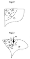
- the cut (E1A) is formed such that it defines a protruding part (E1A) of the first wall (W1), which hinges about a fictitious axis from the plane of the first wall (W1) on exertion of a force (FRC) on part of the first wall (W1) which, viewed from the first folding edge (E1), is positioned beyond the cut (E1A), wherein the force (FRC) has a component perpendicular to the plane of the first wall (W1).
- This embodiment improves the user-friendliness even further, because the insertion of the auxiliary piece in the cut becomes even simpler. Aspects of this embodiment are illustrated in Figures 22 and 23 .
- a guiding construction (E3) which guiding construction (E3) extends over at least part of the cut (E1A), (E1 B) in order to prevent, in operational use, on insertion of the stack of sheets (P) into the cavity, one or more sheets of the stack of sheets (P) being pushed from the inside through the cut (E1A, E1B).
- This embodiment improves the user-friendliness still further, because it prevents, on insertion of the stack of sheets, these sheets being pushed into the cut. This prevents frustration in the user.
- At least one of the first wall (W1) and auxiliary piece (B) on one side is provided with an adhesive layer.
- This embodiment is very advantageous because in this way a stackable device is obtained, which firstly can be packed very easily in large numbers, but which, secondly, can very easily be retrieved from a stack for use. Aspects of this embodiment are illustrated in Figures 15 and 16 .
- the first wall (W1) and the second wall (W2) are formed such that they form a corner device for receiving a corner of the stack of sheets (P).
- This embodiment is highly advantageous for many reasons.
- the corner construction is rigid (even when using flexible materials such as paper), small, covers as little as possible the page and facilitates leafing through the stack.
- the corner construction is only one embodiment. In alternative embodiments the construction is such that this can be pushed over the entire width or entire length of the stack of sheets.
- the same principle can be used, namely that an auxiliary piece is provided which, via a lever arm principle, folds the end of the stack of sheets about the folding edge and in embodiments these are then fixed to the construction or sheets (removably).
- the corner device has closed edges (CE1, CE2) which together, viewed in projection on a plane of the first wall (W1), form an angle in the range of 60° to 120°.
- the range given in this embodiment forms the most practical, wherein an angle of 90° is most advantageous in view of the most common paper formats wherein all corners are 90°.
- the first folding edge (E1) forms an angle in the range of 30° to 60° with at least one of the closed edges (C1, C2) of the corner device.
- the range given in this embodiment forms the most practical, whereby an angle of 45° is most advantageous in view of the most common paper formats wherein all corners are 90°.
- An angle of 45° results in the easiest folding of the sheets.
- a size of the second opening (O2) is configured such that it establishes the predetermined distance (DST1). This applies in particular to the corner device.
- the length of the second opening (O2) lies in the range of 10 to 60 mm.
- the range given in this embodiment forms the most practical in view of the formats of the most common paper, which are A3, A4 or A5.
- the material for each of the first wall (W1), second wall (W2) and auxiliary piece (B) is selected from the group comprising: paper, plastic, wood, metal, biological materials, mixtures of these materials, and other similar materials.
- the materials listed here can all well be used for the device according to the invention. However the use of paper is very advantageous as the material can be shredded without problems in a shredder.
- the first wall (W1), second wall (W2) and auxiliary piece (B) are made of one piece. This embodiment is very advantageous because it is very cheap and quick to manufacture. This embodiment is extremely advantageous when the device is made of paper.
- first wall (W1), second wall (W2) and auxiliary piece (B) are attached to the device as separate components. This can for example be achieved by means of gluing, riveting, and other comparable techniques.
- auxiliary piece (B) can be attached to the device as a separate component.
- auxiliary piece (B) is attached to be pivotable about at least one pivot point (or pivot axis) and whereby the pivot point, in relation to the folding edge (E1), is positioned, and wherein the auxiliary piece is configured such that this at least at one point protrudes beyond the stack of sheets when, in operational use, these are inserted in the device to the maximum pre-specified distance.
- An embodiment of the intermediate product corresponds with regards to shape to one of Figures 7 , 8 and 9 , 20 , 24 and 28 .
- a further improved embodiment of the intermediate product is made of one piece, which is advantageous for the manufacturing of the intermediate product. This can be produced by means of cutting out from the flat sheet and punching the folding lines.
- the described method actually comprises two steps.
- the first step concerns the insertion of the stack of sheets to beyond a folding edge over the entire predetermined distance (for a corner device, this is up to the corner and against the closed edges).
- the second step concerns folding of the end of the stack of sheets using an auxiliary piece which has a lever arm effect on the end of the stack of sheets.
- auxiliary piece which has a lever arm effect on the end of the stack of sheets.
- the invention in a second aspect relates to a stack of devices according to claim 15.
- An advantageous embodiment of the stack is obtained with great value if at least the respective devices in the stack (at least one but preferably all) are provided with an adhesive layer and described in the description variant thereof with double function.
- Such a stack is illustrated in Figures 15 and 16 .
- Embodiments of the invention concern a paper paperclip wherein a good solution is offered for all aspects/properties which are relevant for a paper binder, namely the invention guarantees a good binding quality, the invention is cheap to produce, when fitting the invention the stack of sheets to be joined are not damaged, by the material used, manufacturing process and use of specific embodiments of the invention this is environmentally-friendly and sustainable.
- the invention offers good functionality and is user-friendly when attacjomg and removing the invention. Also specific embodiments of the invention are totally safe for the user to use.
- the invention creates a device for holding together an end of a stack of sheets which is attached with one folding movement (of the auxiliary piece), which is removed with one folding movement, which joins the stack of sheets with one folding movement, and which releases the stack of sheets with one folding movement.
- the connecting principle of the invention works by pushing the stack of sheets to be joined into a closed corner device (space defined by two walls as given in the claims) and folding the corners of the stack of sheets, via an auxiliary construction (auxiliary piece) which uses a lever arm action, about a folding line of the closed corner device. Then there are at least two ways for attaching the auxiliary device with which the stack of sheets are joined, namely:
- a paper binder (device for holding together a stack of sheets or a paperclip) has a number of important functional requirements and properties which a paper binder must fulfil in order to be able to achieve its function, namely to perform the joining of paper well, safely and sustainably.
- the following functional aspects and properties are deemed relevant or may be relevant for a paper binder:
- the object of the embodiments of the invention is to offer a solution for as many important functional requirements and properties as possible which apply or could apply to the connecting of paper as stated in the problem description.
- the invention is intended to create a solution which is more user-friendly than the existing (paper) paperclip solutions.
- rotation axis/pivot axis is defined as an axis or point in relation to which a part (such as the auxiliary piece) can rotate or pivot. It does not necessarily mean an additional component such as a shaft, but this is possible.
- a rotation axis can for example also be formed by a fold seam in a wall, in relation to which part of the wall can pivot. Or it may be that an auxiliary piece is attached rotatably to a wall in another manner.
- the term "stack" is defined as at least two sheets. These sheets can also be made of any type of material. However the invention can also be used on just one sheet. The device is then attached to a corner of the sheet. In this case for example the promotional function can be emphasised by means of a logo on one of the walls of the device.
- folding edge is defined as an edge about which the end of the stack of sheets is folded when fitting the device.
- lever arm is a mechanism with which a small force in combination with a large movement is converted into a small movement which shifts a great load, for which a large force is required. Therefore, in the invention there is a lever arm effect when the stack of sheets is moved over the entire predetermined distance into the cavity between the walls (for a corner device, this means into the corner and against the closed edges).
- the auxiliary piece protrudes at least at one location in the position of the stack of sheets. In addition the further it protrudes, the greater the lever arm effect.
- the lever arm effect is the greatest (and this is therefore the most advantageous embodiment) if the auxiliary piece in unfolded state stands perpendicular to the folding edge.
- the "closed corner device” is defined in this description as the part of the paperclip which comprises the joined front surface with rear surface of the paperclip and the insertion space which is formed between the two surfaces, into which the paper can be inserted. In the claims such a construction is described further.
- first wall W1 and the second wall W2 are illustrated, which have closed edges CE1, CE2 for defining the space for receiving the stack of sheets. Also shown is a first opening 01 on a first end UE1 of the space for receiving the end of the stack of sheets.
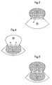
- Figure 1 shows the front view of the end product of the paper paperclip.
- area A is the visible front surface of the paperclip. This part will also remain visible after the paperclip is attached to the stack of sheets and follows the rectangular form of the stack of sheets.
- Area B shows the front of the auxiliary construction (auxiliary construction HB) which is pushed to the rear on folding of the stack of sheets, whereby due to the lever arm effect (the stack of sheets follows the triangular form of area A and does not reach any further, whereby the auxiliary construction is larger than the corners of the stack of sheets which must be folded) the stack of sheets which must be joined is folded without great effort.
- Area C shows the support which serves to facilitate the insertion of the stack of sheets in the closed corner device.
- the part of the paperclip which consists of the joined front surface (area A) with rear surface (area C from the front view and area E from the rear view) of the paperclip and the insertion space between the two surfaces in which the paper can be inserted, is designated in this patent as the "closed corner device".
- Area C is the front of area E from Figure 2 .
- Line A1 is the underside of the front of the visual surface A of the paperclip.
- Figure 2 depicts the first wall W1 and the second wall W2 which have closed edges CE1, CE2 to define the space for receiving the stack of sheets. Also shown is the first opening O1 at a first end UE1 of the space for receiving the end of the stack of sheets and a second opening 02 at the second opposite end UE2 of the space. Furthermore Figure 2 illustrates what is meant by the predetermined distance DST1 over which the stack of sheets protrudes in operational use. It appears from Figure 2 that this distance is determined amongst others by the size of the second opening 02.
- line E1 gives the folding line (folding edge) around which the corner of the stack of sheets to be joined is folded.
- Line D1 gives the folding line over which the auxiliary construction is folded. Folding line D1 resides a small distance above folding line E1 over which the stack of sheets is folded. The reason for this is that the folded paper obtains a certain thickness. If the space between D1 and E1 were not present, the auxiliary construction would be partly bent with the stack of sheets to be joined, whereby the height of area D (and B in the fixed state in Figure 6 ) would be too small to be able to be attached securely. This would reduce the binding quality.
- Figure 6 further shows an area G. This is part of the back side of the visible front surface A.
- the invention can be produced from one piece of paper. It is also possible to produce the invention in parts, wherein the end product can have the same external features and the same functionalities as described in this application.
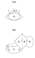
- Figures 7 to 9 show variants of the flat sheet model of the invention where this is made from one piece of paper.
- the dotted lines A1, EA3, E3B, D1 and J1 in Figures 7 , 8 and 9 are perforated or ribbed folding lines.
- the surface H is folded to the back against the visible front surface A.
- the back side of surface H can be glued to the back side of surface A.
- surface H acts as a guide surface on insertion of the stack of sheets to be joined.
- surface I in Figure 7 or surface J in Figure 8 is folded backward over folding line E3A.
- a layer of glue is attached on surfaces I or J.
- Surface C is folded backward over folding line E3B, whereby surface I or J is glued against surface H. This gives the end product of this one embodiment of the invention, the paper paperclip.
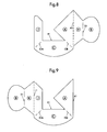
- Figure 9 shows an alternative flat sheet model of the paper paperclip wherein first the surface K is folded forward over folding line J1 and wherein the front surface of surface K is glued against the front surface of surface K. Then surface J is folded backward about folding line E3A. On the back side of surface K is applied a glue layer which, after folding surface C to the back over folding line E3B, is glued to the back side of the visible front surface A.
- the advantage in this variant is that the visible front surface A is not connected in a straight line but can have other forms.
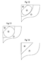
- Figure 10 shows how the stack of sheets P in the closed corner device of the paperclip appear in open state in relation to the visible front surface A, wherein the front of the auxiliary construction B is still visible.
- Figure 11 shows the back side of the paperclip in open state, clearly revealing how the stack of sheets P resides in the closed corner device and how the adhesive layer is attached to the auxiliary construction at surface D according to Figure 2 .
- Figure 12 shows the paperclip in closed state, clearly revealing how the paper P resides in the clip in closed state.
- Area G is the back side of the visible front surface A and area B is the front side of the auxiliary construction in closed state.
- Figure 13 shows the paperclip in accordance with another embodiment of the invention.
- FIG. 14 shows the front view of the paperclip in closed state where it is visible how the stack of sheets P resides in the paperclip and wherein area A is the visible front surface.
- Figure 15 shows the back sides of the paper paperclip in the stacked position.
- Area D is here the back view of the auxiliary construction and area E is the back side of the closed corner device.
- the paperclips remain stacked at their position by the adhesive layer which is shown hatched on area E.
- Figure 16 shows a front view of the stacked paperclips.
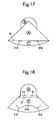
- Figure 17 shows the front view of the paper paperclip.
- Area A is the visible front side of the paperclip. This part will also remain visible after the paperclip is attached to the stack of sheets and follows the form of the stack of sheets.
- Area B shows the front of the auxiliary construction, area C shows the support which facilitates the insertion of the stack of sheets for joining.
- This is the front of area E from Figure 18 .
- Figures 20 and 21 show a guiding construction (E3) which when folded comes to reside on surface E and protrudes beyond the highest point of the fixing cut E1A. As a result the paper can no longer catch.
- Line A1 in Figure 17 is the underside of the front of the visible surface A of the paperclip.
- E1 B which is visible twice below line A1 shows the lowest part of the fixing cut which in Figure 18 is marked as E1A and E1B.
- the fixing cut is a fully perforated line.
- point E1A lifts whereby the auxiliary construction (area D in unattached state and area B in Figure 19 in attached state) can easily enter the fixing cut, securing the auxiliary construction behind the fixing cut as shown in Figure 19 .
- line E2 gives the folding line about which the stack of sheets to be joined is folded.
- Line D1 shows the folding line over which the auxiliary construction is folded.
- Figure 19 further shows area G. This is part of the back side of the visible front surface A.
- FIGs 22 and 23 show the back side of the paperclip wherein auxiliary construction B is visible and remains attached in the fixing cut, because the auxiliary construction resides partly below E1A.
- Figure 23 again explicitly shows how the pivoting construction of the fixing cut works.
- the fixing cut comprising the punched line (E1A, E1 B) pivots over pivot line A1 when a force FRC is exerted downward on the part below the fixing cut in area E.
- FRC force exerted downward on the part below the fixing cut in area E.
- E1A lifts whereby the auxiliary construction can easily be pushed under the fixing cut.
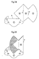
- Figures 24 to 27 show the steps of the manufacturing process of the paperclip with adhesive layer as a binding principle, wherein the steps comprise three folding movements and one or two adhesive joints.
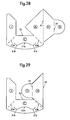
- Figures 28 to 31 show the steps of the manufacturing process of the paperclip with a retaining system as binding principle, wherein the steps comprise three folding movements and one or two adhesive joints.
- the invention relates to a device for holding together a stack of sheets which has a good binding quality, is simple, intuitive and quick to attach, offers multiple functionalities, uses sustainable materials and can be used safely. Because of the simple construction, the invention can be manufactured cheaply and quickly and offers a good solution for the business market wherein speed of attachment, good binding quality and a sustainable appearance together with the combined functionalities (joining paper, promotional expression by means of printed logos on the clip, marking possibilities) offers added value in comparison with existing solutions. For the retail market the invention also offers a good alternative to existing solutions. Certain embodiments of the invention are cheap, sustainable, function well and offer numerous possibilities for application.
- the function of the invention is based on a number of basic principles, the most important of which are: visually clearly distinguished areas renders the use intuitive, by using a lever arm effect minimises the effort required for fixing, by using, in certain embodiments, an adhesive layer or a retaining system the fixing requires particularly few actions, whereby the invention is simple, intuitive and functions appropriately.
- the invention can be used in various application areas. It can be used amongst others in office environments, but also certainly in all households.
Landscapes
- Sheet Holders (AREA)
- Folding Of Thin Sheet-Like Materials, Special Discharging Devices, And Others (AREA)
- Pile Receivers (AREA)
- Cartons (AREA)
- Supports Or Holders For Household Use (AREA)
Priority Applications (1)
| Application Number | Priority Date | Filing Date | Title |
|---|---|---|---|
| EP12702268.9A EP2670607B1 (en) | 2011-02-04 | 2012-02-03 | Device for holding together a stack of sheets |
Applications Claiming Priority (4)
| Application Number | Priority Date | Filing Date | Title |
|---|---|---|---|
| NL1038563A NL1038563C2 (nl) | 2011-02-04 | 2011-02-04 | Papieren paperclip met hechtingsprincipe. |
| EP11154027 | 2011-02-10 | ||
| PCT/EP2012/051854 WO2012104413A1 (en) | 2011-02-04 | 2012-02-03 | Device for holding together a stack of sheets |
| EP12702268.9A EP2670607B1 (en) | 2011-02-04 | 2012-02-03 | Device for holding together a stack of sheets |
Publications (2)
| Publication Number | Publication Date |
|---|---|
| EP2670607A1 EP2670607A1 (en) | 2013-12-11 |
| EP2670607B1 true EP2670607B1 (en) | 2014-12-10 |
Family
ID=45562336
Family Applications (1)
| Application Number | Title | Priority Date | Filing Date |
|---|---|---|---|
| EP12702268.9A Not-in-force EP2670607B1 (en) | 2011-02-04 | 2012-02-03 | Device for holding together a stack of sheets |
Country Status (10)
| Country | Link |
|---|---|
| US (1) | US9283800B2 (enExample) |
| EP (1) | EP2670607B1 (enExample) |
| JP (1) | JP5970479B2 (enExample) |
| CN (1) | CN103561964B (enExample) |
| BR (1) | BR112013019622A2 (enExample) |
| CA (1) | CA2826509A1 (enExample) |
| MX (1) | MX2013008899A (enExample) |
| RU (1) | RU2013140666A (enExample) |
| SG (1) | SG192100A1 (enExample) |
| WO (1) | WO2012104413A1 (enExample) |
Families Citing this family (4)
| Publication number | Priority date | Publication date | Assignee | Title |
|---|---|---|---|---|
| JP6387805B2 (ja) * | 2014-11-19 | 2018-09-12 | マックス株式会社 | 綴じ装置 |
| TWI697415B (zh) * | 2018-11-08 | 2020-07-01 | 鵬展國際有限公司 | 置物用便利角貼及其製作方法 |
| USD892929S1 (en) | 2019-06-06 | 2020-08-11 | James Siggens | Page marker |
| GB2578501B (en) * | 2019-07-04 | 2021-02-24 | Caroline Gardner Publishing Ltd | Greetings card packaging |
Family Cites Families (12)
| Publication number | Priority date | Publication date | Assignee | Title |
|---|---|---|---|---|
| GB138962A (en) * | 1919-01-15 | 1920-02-26 | Alexander John Philip | An improved paper fastener or binder |
| US2326366A (en) * | 1942-10-10 | 1943-08-10 | Orland A Krenke | Paper fastener |
| US2843901A (en) * | 1955-09-09 | 1958-07-22 | Edward Z Bukowski | Corner paper clip |
| USD271213S (en) * | 1981-05-28 | 1983-11-01 | Hisao Sato | Gummed stack of paper clips |
| NL1011526C2 (nl) | 1999-03-11 | 2001-05-02 | Josephus Petrus Theodorus Van | Papieren hoekinrichting voor het vasthouden van vellen papier en werkwijze voor het vormen daarvan. |
| JP2001180166A (ja) * | 1999-12-27 | 2001-07-03 | Kouichi Fukiya | コーナークリップ |
| NL1017399C1 (nl) * | 2001-02-19 | 2002-08-20 | Hubertus Johannes Ber Schoeren | Werkwijze voor het met behulp van een klemelement inklemmen van tenminste een vel papier en klemelement geschikt voor gebruik daarin. |
| JP2003251958A (ja) * | 2002-03-06 | 2003-09-09 | Tadashi Saito | 切断プレス機製造方法 |
| CN100515797C (zh) * | 2004-07-21 | 2009-07-22 | 查尔斯·D·拉姆斯登 | 边角装置和边角装置附着工具 |
| CN2871216Y (zh) * | 2005-08-10 | 2007-02-21 | 上海云静企业发展有限公司 | 柔韧纸夹 |
| JP2007245698A (ja) * | 2005-09-02 | 2007-09-27 | Satoshi Shintani | クリップ |
| JP3127609U (ja) * | 2006-09-27 | 2006-12-07 | 順彦 佐藤 | 用紙角部を綴じるシート片 |
-
2012
- 2012-02-03 JP JP2013552217A patent/JP5970479B2/ja not_active Expired - Fee Related
- 2012-02-03 MX MX2013008899A patent/MX2013008899A/es not_active Application Discontinuation
- 2012-02-03 US US13/981,726 patent/US9283800B2/en not_active Expired - Fee Related
- 2012-02-03 CN CN201280014579.6A patent/CN103561964B/zh not_active Expired - Fee Related
- 2012-02-03 WO PCT/EP2012/051854 patent/WO2012104413A1/en not_active Ceased
- 2012-02-03 EP EP12702268.9A patent/EP2670607B1/en not_active Not-in-force
- 2012-02-03 RU RU2013140666/12A patent/RU2013140666A/ru not_active Application Discontinuation
- 2012-02-03 BR BR112013019622A patent/BR112013019622A2/pt not_active IP Right Cessation
- 2012-02-03 CA CA2826509A patent/CA2826509A1/en not_active Abandoned
- 2012-02-03 SG SG2013056163A patent/SG192100A1/en unknown
Also Published As
| Publication number | Publication date |
|---|---|
| BR112013019622A2 (pt) | 2017-06-13 |
| JP5970479B2 (ja) | 2016-08-17 |
| WO2012104413A1 (en) | 2012-08-09 |
| US9283800B2 (en) | 2016-03-15 |
| CN103561964A (zh) | 2014-02-05 |
| CA2826509A1 (en) | 2012-08-09 |
| MX2013008899A (es) | 2013-12-06 |
| JP2014504568A (ja) | 2014-02-24 |
| SG192100A1 (en) | 2013-08-30 |
| US20130305501A1 (en) | 2013-11-21 |
| CN103561964B (zh) | 2016-02-24 |
| EP2670607A1 (en) | 2013-12-11 |
| RU2013140666A (ru) | 2015-03-10 |
Similar Documents
| Publication | Publication Date | Title |
|---|---|---|
| EP2670607B1 (en) | Device for holding together a stack of sheets | |
| EP2807037B1 (en) | Cover, coupling element and folder | |
| JP2006188031A (ja) | 付箋台紙及びこの付箋台紙を綴じ込んだシステム手帳 | |
| JP3176274U (ja) | 紙製クリアファイル | |
| JP2011131392A (ja) | 製本システム | |
| US8814214B2 (en) | Apparatus and device for providing book protection | |
| US20090283576A1 (en) | Customizable folder | |
| JP7537697B2 (ja) | 挟持具 | |
| KR20130007146U (ko) | 포켓이 형성된 포스트잇 | |
| CN209684188U (zh) | 提拉式快速组立的容置盒 | |
| NL1038563C2 (nl) | Papieren paperclip met hechtingsprincipe. | |
| CN213385631U (zh) | 一种纸板边角保护罩 | |
| JP2012066523A (ja) | 集冊ファイル用別冊、集冊ファイル用別冊の表紙部及び集冊ファイル用別冊の綴じ込み方法 | |
| JP3158574U (ja) | 冊子 | |
| CN209938107U (zh) | 一种指甲位可撕文件夹 | |
| CN210761730U (zh) | 一种简易拼装文件盒 | |
| KR200280201Y1 (ko) | 문서의 제본 구조 | |
| JP3512747B2 (ja) | 簡易ポケット | |
| KR200180542Y1 (ko) | 두께조절기능을 갖는 접착식 북 커버 | |
| JP3141481U (ja) | 組み立て箱 | |
| JP3210061U (ja) | ファイルフォルダ | |
| CN204870171U (zh) | 新型文件夹 | |
| JP3110188U (ja) | 多目的クリップ | |
| KR200183130Y1 (ko) | 두께조절기능을 갖는 일체형 접착식 북 커버 | |
| JP3123317U (ja) | ファイリング・カバー |
Legal Events
| Date | Code | Title | Description |
|---|---|---|---|
| PUAI | Public reference made under article 153(3) epc to a published international application that has entered the european phase |
Free format text: ORIGINAL CODE: 0009012 |
|
| 17P | Request for examination filed |
Effective date: 20130904 |
|
| AK | Designated contracting states |
Kind code of ref document: A1 Designated state(s): AL AT BE BG CH CY CZ DE DK EE ES FI FR GB GR HR HU IE IS IT LI LT LU LV MC MK MT NL NO PL PT RO RS SE SI SK SM TR |
|
| DAX | Request for extension of the european patent (deleted) | ||
| RIN1 | Information on inventor provided before grant (corrected) |
Inventor name: VAN DEN BOGAARD, JOSEPHUS PETRUS THEODORUS Inventor name: VAN DEN BOGAARD, JOHANNES ADRIANUS Inventor name: VAN DEN BOGAARD, THEODORUS FRANCISCUS |
|
| REG | Reference to a national code |
Ref country code: HK Ref legal event code: DE Ref document number: 1189551 Country of ref document: HK |
|
| GRAP | Despatch of communication of intention to grant a patent |
Free format text: ORIGINAL CODE: EPIDOSNIGR1 |
|
| INTG | Intention to grant announced |
Effective date: 20140701 |
|
| GRAS | Grant fee paid |
Free format text: ORIGINAL CODE: EPIDOSNIGR3 |
|
| GRAA | (expected) grant |
Free format text: ORIGINAL CODE: 0009210 |
|
| AK | Designated contracting states |
Kind code of ref document: B1 Designated state(s): AL AT BE BG CH CY CZ DE DK EE ES FI FR GB GR HR HU IE IS IT LI LT LU LV MC MK MT NL NO PL PT RO RS SE SI SK SM TR |
|
| REG | Reference to a national code |
Ref country code: GB Ref legal event code: FG4D |
|
| REG | Reference to a national code |
Ref country code: CH Ref legal event code: EP |
|
| REG | Reference to a national code |
Ref country code: IE Ref legal event code: FG4D |
|
| REG | Reference to a national code |
Ref country code: AT Ref legal event code: REF Ref document number: 700451 Country of ref document: AT Kind code of ref document: T Effective date: 20150115 |
|
| REG | Reference to a national code |
Ref country code: DE Ref legal event code: R096 Ref document number: 602012004236 Country of ref document: DE Effective date: 20150122 |
|
| REG | Reference to a national code |
Ref country code: FR Ref legal event code: PLFP Year of fee payment: 4 |
|
| REG | Reference to a national code |
Ref country code: NL Ref legal event code: T3 |
|
| REG | Reference to a national code |
Ref country code: AT Ref legal event code: MK05 Ref document number: 700451 Country of ref document: AT Kind code of ref document: T Effective date: 20141210 |
|
| PG25 | Lapsed in a contracting state [announced via postgrant information from national office to epo] |
Ref country code: NO Free format text: LAPSE BECAUSE OF FAILURE TO SUBMIT A TRANSLATION OF THE DESCRIPTION OR TO PAY THE FEE WITHIN THE PRESCRIBED TIME-LIMIT Effective date: 20150310 Ref country code: ES Free format text: LAPSE BECAUSE OF FAILURE TO SUBMIT A TRANSLATION OF THE DESCRIPTION OR TO PAY THE FEE WITHIN THE PRESCRIBED TIME-LIMIT Effective date: 20141210 Ref country code: LT Free format text: LAPSE BECAUSE OF FAILURE TO SUBMIT A TRANSLATION OF THE DESCRIPTION OR TO PAY THE FEE WITHIN THE PRESCRIBED TIME-LIMIT Effective date: 20141210 Ref country code: FI Free format text: LAPSE BECAUSE OF FAILURE TO SUBMIT A TRANSLATION OF THE DESCRIPTION OR TO PAY THE FEE WITHIN THE PRESCRIBED TIME-LIMIT Effective date: 20141210 |
|
| REG | Reference to a national code |
Ref country code: LT Ref legal event code: MG4D |
|
| PG25 | Lapsed in a contracting state [announced via postgrant information from national office to epo] |
Ref country code: GR Free format text: LAPSE BECAUSE OF FAILURE TO SUBMIT A TRANSLATION OF THE DESCRIPTION OR TO PAY THE FEE WITHIN THE PRESCRIBED TIME-LIMIT Effective date: 20150311 Ref country code: RS Free format text: LAPSE BECAUSE OF FAILURE TO SUBMIT A TRANSLATION OF THE DESCRIPTION OR TO PAY THE FEE WITHIN THE PRESCRIBED TIME-LIMIT Effective date: 20141210 Ref country code: AT Free format text: LAPSE BECAUSE OF FAILURE TO SUBMIT A TRANSLATION OF THE DESCRIPTION OR TO PAY THE FEE WITHIN THE PRESCRIBED TIME-LIMIT Effective date: 20141210 Ref country code: LV Free format text: LAPSE BECAUSE OF FAILURE TO SUBMIT A TRANSLATION OF THE DESCRIPTION OR TO PAY THE FEE WITHIN THE PRESCRIBED TIME-LIMIT Effective date: 20141210 Ref country code: SE Free format text: LAPSE BECAUSE OF FAILURE TO SUBMIT A TRANSLATION OF THE DESCRIPTION OR TO PAY THE FEE WITHIN THE PRESCRIBED TIME-LIMIT Effective date: 20141210 Ref country code: HR Free format text: LAPSE BECAUSE OF FAILURE TO SUBMIT A TRANSLATION OF THE DESCRIPTION OR TO PAY THE FEE WITHIN THE PRESCRIBED TIME-LIMIT Effective date: 20141210 |
|
| PG25 | Lapsed in a contracting state [announced via postgrant information from national office to epo] |
Ref country code: PT Free format text: LAPSE BECAUSE OF FAILURE TO SUBMIT A TRANSLATION OF THE DESCRIPTION OR TO PAY THE FEE WITHIN THE PRESCRIBED TIME-LIMIT Effective date: 20150410 Ref country code: EE Free format text: LAPSE BECAUSE OF FAILURE TO SUBMIT A TRANSLATION OF THE DESCRIPTION OR TO PAY THE FEE WITHIN THE PRESCRIBED TIME-LIMIT Effective date: 20141210 Ref country code: SK Free format text: LAPSE BECAUSE OF FAILURE TO SUBMIT A TRANSLATION OF THE DESCRIPTION OR TO PAY THE FEE WITHIN THE PRESCRIBED TIME-LIMIT Effective date: 20141210 Ref country code: CZ Free format text: LAPSE BECAUSE OF FAILURE TO SUBMIT A TRANSLATION OF THE DESCRIPTION OR TO PAY THE FEE WITHIN THE PRESCRIBED TIME-LIMIT Effective date: 20141210 Ref country code: RO Free format text: LAPSE BECAUSE OF FAILURE TO SUBMIT A TRANSLATION OF THE DESCRIPTION OR TO PAY THE FEE WITHIN THE PRESCRIBED TIME-LIMIT Effective date: 20141210 |
|
| PG25 | Lapsed in a contracting state [announced via postgrant information from national office to epo] |
Ref country code: IS Free format text: LAPSE BECAUSE OF FAILURE TO SUBMIT A TRANSLATION OF THE DESCRIPTION OR TO PAY THE FEE WITHIN THE PRESCRIBED TIME-LIMIT Effective date: 20150410 Ref country code: PL Free format text: LAPSE BECAUSE OF FAILURE TO SUBMIT A TRANSLATION OF THE DESCRIPTION OR TO PAY THE FEE WITHIN THE PRESCRIBED TIME-LIMIT Effective date: 20141210 |
|
| REG | Reference to a national code |
Ref country code: DE Ref legal event code: R097 Ref document number: 602012004236 Country of ref document: DE |
|
| PG25 | Lapsed in a contracting state [announced via postgrant information from national office to epo] |
Ref country code: LU Free format text: LAPSE BECAUSE OF FAILURE TO SUBMIT A TRANSLATION OF THE DESCRIPTION OR TO PAY THE FEE WITHIN THE PRESCRIBED TIME-LIMIT Effective date: 20150203 |
|
| REG | Reference to a national code |
Ref country code: CH Ref legal event code: PL |
|
| PLBE | No opposition filed within time limit |
Free format text: ORIGINAL CODE: 0009261 |
|
| STAA | Information on the status of an ep patent application or granted ep patent |
Free format text: STATUS: NO OPPOSITION FILED WITHIN TIME LIMIT |
|
| PG25 | Lapsed in a contracting state [announced via postgrant information from national office to epo] |
Ref country code: MC Free format text: LAPSE BECAUSE OF FAILURE TO SUBMIT A TRANSLATION OF THE DESCRIPTION OR TO PAY THE FEE WITHIN THE PRESCRIBED TIME-LIMIT Effective date: 20141210 Ref country code: LI Free format text: LAPSE BECAUSE OF NON-PAYMENT OF DUE FEES Effective date: 20150228 Ref country code: DK Free format text: LAPSE BECAUSE OF FAILURE TO SUBMIT A TRANSLATION OF THE DESCRIPTION OR TO PAY THE FEE WITHIN THE PRESCRIBED TIME-LIMIT Effective date: 20141210 Ref country code: CH Free format text: LAPSE BECAUSE OF NON-PAYMENT OF DUE FEES Effective date: 20150228 |
|
| 26N | No opposition filed |
Effective date: 20150911 |
|
| REG | Reference to a national code |
Ref country code: IE Ref legal event code: MM4A |
|
| PG25 | Lapsed in a contracting state [announced via postgrant information from national office to epo] |
Ref country code: IT Free format text: LAPSE BECAUSE OF FAILURE TO SUBMIT A TRANSLATION OF THE DESCRIPTION OR TO PAY THE FEE WITHIN THE PRESCRIBED TIME-LIMIT Effective date: 20141210 |
|
| PG25 | Lapsed in a contracting state [announced via postgrant information from national office to epo] |
Ref country code: IE Free format text: LAPSE BECAUSE OF NON-PAYMENT OF DUE FEES Effective date: 20150203 |
|
| REG | Reference to a national code |
Ref country code: FR Ref legal event code: PLFP Year of fee payment: 5 |
|
| PG25 | Lapsed in a contracting state [announced via postgrant information from national office to epo] |
Ref country code: SI Free format text: LAPSE BECAUSE OF FAILURE TO SUBMIT A TRANSLATION OF THE DESCRIPTION OR TO PAY THE FEE WITHIN THE PRESCRIBED TIME-LIMIT Effective date: 20141210 |
|
| PG25 | Lapsed in a contracting state [announced via postgrant information from national office to epo] |
Ref country code: BE Free format text: LAPSE BECAUSE OF FAILURE TO SUBMIT A TRANSLATION OF THE DESCRIPTION OR TO PAY THE FEE WITHIN THE PRESCRIBED TIME-LIMIT Effective date: 20141210 |
|
| PG25 | Lapsed in a contracting state [announced via postgrant information from national office to epo] |
Ref country code: MT Free format text: LAPSE BECAUSE OF FAILURE TO SUBMIT A TRANSLATION OF THE DESCRIPTION OR TO PAY THE FEE WITHIN THE PRESCRIBED TIME-LIMIT Effective date: 20141210 |
|
| REG | Reference to a national code |
Ref country code: FR Ref legal event code: PLFP Year of fee payment: 6 |
|
| PG25 | Lapsed in a contracting state [announced via postgrant information from national office to epo] |
Ref country code: SM Free format text: LAPSE BECAUSE OF FAILURE TO SUBMIT A TRANSLATION OF THE DESCRIPTION OR TO PAY THE FEE WITHIN THE PRESCRIBED TIME-LIMIT Effective date: 20141210 Ref country code: BG Free format text: LAPSE BECAUSE OF FAILURE TO SUBMIT A TRANSLATION OF THE DESCRIPTION OR TO PAY THE FEE WITHIN THE PRESCRIBED TIME-LIMIT Effective date: 20141210 Ref country code: HU Free format text: LAPSE BECAUSE OF FAILURE TO SUBMIT A TRANSLATION OF THE DESCRIPTION OR TO PAY THE FEE WITHIN THE PRESCRIBED TIME-LIMIT; INVALID AB INITIO Effective date: 20120203 |
|
| PG25 | Lapsed in a contracting state [announced via postgrant information from national office to epo] |
Ref country code: CY Free format text: LAPSE BECAUSE OF FAILURE TO SUBMIT A TRANSLATION OF THE DESCRIPTION OR TO PAY THE FEE WITHIN THE PRESCRIBED TIME-LIMIT Effective date: 20141210 |
|
| PG25 | Lapsed in a contracting state [announced via postgrant information from national office to epo] |
Ref country code: TR Free format text: LAPSE BECAUSE OF FAILURE TO SUBMIT A TRANSLATION OF THE DESCRIPTION OR TO PAY THE FEE WITHIN THE PRESCRIBED TIME-LIMIT Effective date: 20141210 |
|
| REG | Reference to a national code |
Ref country code: FR Ref legal event code: PLFP Year of fee payment: 7 |
|
| PG25 | Lapsed in a contracting state [announced via postgrant information from national office to epo] |
Ref country code: MK Free format text: LAPSE BECAUSE OF FAILURE TO SUBMIT A TRANSLATION OF THE DESCRIPTION OR TO PAY THE FEE WITHIN THE PRESCRIBED TIME-LIMIT Effective date: 20141210 |
|
| PG25 | Lapsed in a contracting state [announced via postgrant information from national office to epo] |
Ref country code: AL Free format text: LAPSE BECAUSE OF FAILURE TO SUBMIT A TRANSLATION OF THE DESCRIPTION OR TO PAY THE FEE WITHIN THE PRESCRIBED TIME-LIMIT Effective date: 20141210 |
|
| PGFP | Annual fee paid to national office [announced via postgrant information from national office to epo] |
Ref country code: GB Payment date: 20200227 Year of fee payment: 9 |
|
| REG | Reference to a national code |
Ref country code: HK Ref legal event code: WD Ref document number: 1189551 Country of ref document: HK |
|
| REG | Reference to a national code |
Ref country code: NL Ref legal event code: PD Owner name: CLIPFACTORY B.V.; NL Free format text: DETAILS ASSIGNMENT: CHANGE OF OWNER(S), ASSIGNMENT; FORMER OWNER NAME: DELTACLIP INTERNATIONAL B.V. Effective date: 20210118 |
|
| REG | Reference to a national code |
Ref country code: DE Ref legal event code: R081 Ref document number: 602012004236 Country of ref document: DE Owner name: CLIPFACTORY B.V., NL Free format text: FORMER OWNER: DELTACLIP INTERNATIONAL B.V., EINDHOVEN, NL |
|
| GBPC | Gb: european patent ceased through non-payment of renewal fee |
Effective date: 20210203 |
|
| PG25 | Lapsed in a contracting state [announced via postgrant information from national office to epo] |
Ref country code: GB Free format text: LAPSE BECAUSE OF NON-PAYMENT OF DUE FEES Effective date: 20210203 |
|
| PGFP | Annual fee paid to national office [announced via postgrant information from national office to epo] |
Ref country code: DE Payment date: 20220225 Year of fee payment: 11 |
|
| PGFP | Annual fee paid to national office [announced via postgrant information from national office to epo] |
Ref country code: NL Payment date: 20220224 Year of fee payment: 11 Ref country code: FR Payment date: 20220223 Year of fee payment: 11 |
|
| REG | Reference to a national code |
Ref country code: DE Ref legal event code: R119 Ref document number: 602012004236 Country of ref document: DE |
|
| REG | Reference to a national code |
Ref country code: NL Ref legal event code: MM Effective date: 20230301 |
|
| PG25 | Lapsed in a contracting state [announced via postgrant information from national office to epo] |
Ref country code: NL Free format text: LAPSE BECAUSE OF NON-PAYMENT OF DUE FEES Effective date: 20230301 |
|
| PG25 | Lapsed in a contracting state [announced via postgrant information from national office to epo] |
Ref country code: FR Free format text: LAPSE BECAUSE OF NON-PAYMENT OF DUE FEES Effective date: 20230228 Ref country code: DE Free format text: LAPSE BECAUSE OF NON-PAYMENT OF DUE FEES Effective date: 20230901 |