EP2670184B1 - Procédé de gestion de réseau par assistance depuis un terminal utilisant une signalisation de plan de commande et demandes du réseau au terminal - Google Patents
Procédé de gestion de réseau par assistance depuis un terminal utilisant une signalisation de plan de commande et demandes du réseau au terminal Download PDFInfo
- Publication number
- EP2670184B1 EP2670184B1 EP13181914.6A EP13181914A EP2670184B1 EP 2670184 B1 EP2670184 B1 EP 2670184B1 EP 13181914 A EP13181914 A EP 13181914A EP 2670184 B1 EP2670184 B1 EP 2670184B1
- Authority
- EP
- European Patent Office
- Prior art keywords
- network
- event
- reporting
- measurements
- block
- Prior art date
- Legal status (The legal status is an assumption and is not a legal conclusion. Google has not performed a legal analysis and makes no representation as to the accuracy of the status listed.)
- Active
Links
- 238000000034 method Methods 0.000 title claims description 141
- 230000011664 signaling Effects 0.000 title claims description 27
- 238000004891 communication Methods 0.000 claims description 61
- 238000005259 measurement Methods 0.000 claims description 50
- 230000004044 response Effects 0.000 claims description 15
- 230000008859 change Effects 0.000 claims description 7
- 238000004590 computer program Methods 0.000 claims description 3
- 230000005641 tunneling Effects 0.000 claims 2
- 238000010586 diagram Methods 0.000 description 63
- 238000005457 optimization Methods 0.000 description 34
- 238000007726 management method Methods 0.000 description 33
- 230000005540 biological transmission Effects 0.000 description 18
- 238000005516 engineering process Methods 0.000 description 14
- 230000008569 process Effects 0.000 description 13
- 230000006870 function Effects 0.000 description 12
- 238000012545 processing Methods 0.000 description 10
- 230000009471 action Effects 0.000 description 9
- 238000012360 testing method Methods 0.000 description 8
- 230000000670 limiting effect Effects 0.000 description 6
- 230000002776 aggregation Effects 0.000 description 5
- 238000004220 aggregation Methods 0.000 description 5
- 238000013433 optimization analysis Methods 0.000 description 5
- 230000007246 mechanism Effects 0.000 description 4
- 230000008520 organization Effects 0.000 description 4
- 230000001143 conditioned effect Effects 0.000 description 3
- 238000012544 monitoring process Methods 0.000 description 3
- 230000000737 periodic effect Effects 0.000 description 3
- 238000012546 transfer Methods 0.000 description 3
- 238000004458 analytical method Methods 0.000 description 2
- 238000013459 approach Methods 0.000 description 2
- 230000001413 cellular effect Effects 0.000 description 2
- 238000001514 detection method Methods 0.000 description 2
- 239000000835 fiber Substances 0.000 description 2
- 230000000977 initiatory effect Effects 0.000 description 2
- 230000003287 optical effect Effects 0.000 description 2
- 230000002441 reversible effect Effects 0.000 description 2
- 241000204801 Muraenidae Species 0.000 description 1
- 230000004075 alteration Effects 0.000 description 1
- 230000009286 beneficial effect Effects 0.000 description 1
- 230000008901 benefit Effects 0.000 description 1
- 239000003795 chemical substances by application Substances 0.000 description 1
- 230000000295 complement effect Effects 0.000 description 1
- 230000000694 effects Effects 0.000 description 1
- 230000036541 health Effects 0.000 description 1
- 230000003993 interaction Effects 0.000 description 1
- 230000002452 interceptive effect Effects 0.000 description 1
- 230000001788 irregular Effects 0.000 description 1
- 230000007774 longterm Effects 0.000 description 1
- 238000010295 mobile communication Methods 0.000 description 1
- 238000012986 modification Methods 0.000 description 1
- 230000004048 modification Effects 0.000 description 1
- 230000006855 networking Effects 0.000 description 1
- 238000013139 quantization Methods 0.000 description 1
- 230000002829 reductive effect Effects 0.000 description 1
- 230000000717 retained effect Effects 0.000 description 1
- 238000012956 testing procedure Methods 0.000 description 1
- 230000001960 triggered effect Effects 0.000 description 1
Images


Classifications
-
- H—ELECTRICITY
- H04—ELECTRIC COMMUNICATION TECHNIQUE
- H04J—MULTIPLEX COMMUNICATION
- H04J3/00—Time-division multiplex systems
- H04J3/02—Details
- H04J3/14—Monitoring arrangements
-
- H—ELECTRICITY
- H04—ELECTRIC COMMUNICATION TECHNIQUE
- H04W—WIRELESS COMMUNICATION NETWORKS
- H04W24/00—Supervisory, monitoring or testing arrangements
- H04W24/02—Arrangements for optimising operational condition
-
- H—ELECTRICITY
- H04—ELECTRIC COMMUNICATION TECHNIQUE
- H04W—WIRELESS COMMUNICATION NETWORKS
- H04W24/00—Supervisory, monitoring or testing arrangements
- H04W24/10—Scheduling measurement reports ; Arrangements for measurement reports
Definitions
- the present disclosure relates generally to network communications, and more specifically to techniques for network management and optimization.
- Wireless communication systems are widely deployed to provide various communication services; for instance, voice, video, packet data, broadcast, and messaging services can be provided via such wireless communication systems.
- These systems can be multiple-access systems that are capable of supporting communication for multiple terminals by sharing available system resources. Examples of such multiple-access systems include Code Division Multiple Access (CDMA) systems, Time Division Multiple Access (TDMA) systems, Frequency Division Multiple Access (FDMA) systems, and Orthogonal Frequency Division Multiple Access (OFDMA) systems.
- CDMA Code Division Multiple Access
- TDMA Time Division Multiple Access
- FDMA Frequency Division Multiple Access
- OFDMA Orthogonal Frequency Division Multiple Access
- a wireless multiple-access communication system can simultaneously support communication for multiple wireless terminals.
- each terminal can communicate with one or more base stations via transmissions on the forward and reverse links.
- the forward link (or downlink) refers to the communication link from the base stations to the terminals
- the reverse link (or uplink) refers to the communication link from the terminals to the base stations.
- This communication link can be established via a single-in-single-out (SISO), multiple-in-signal-out (MISO), or a multiple-in-multiple-out (MIMO) system.
- SISO single-in-single-out
- MISO multiple-in-signal-out
- MIMO multiple-in-multiple-out
- Communication networks are utilized to provide communication service to an assortment of communication terminals and/or other devices via a wired or wireless networking technology and/or a combination of technologies.
- one or more network entities are responsible for optimizing the performance of the network for the devices that utilize the network.
- Such network entities can, for example, optimize network operations based on measurements and/or other observations received from various devices and/or locations in the network.
- obtaining the necessary measurements for network optimization can require significant operational expense.
- existing communication networks require costly techniques such as manual drive testing, wherein devices are manually moved throughout the network and tested in various locations in the network.
- US 20060128371 A1 discloses using a communication system to optimize system performances by selectively managing which mobile stations (MSs) are to server as test MSs, in which a device management and system optimisation server (DMSOS) can multicast/unicast through a broadcast server system parameter measurement and report polices to mobile stations in certain areas, and the selected mobile stations can report measurements upon a request from the network.
- MSs mobile stations
- DMSOS device management and system optimisation server
- 3GPP paper R3-072118 from Qualcomm Europe presents a framework to standardize and automate the collection of measurements that can be used for RF optimization purposes in LTE networks, which states that SON server is able to configure and collect measurements from user equipment.
- Yet another aspect relates to an apparatus that facilitates implementation of the above described method as in the appended claim 7.
- Still another aspect relates to a computer program product, which can comprise a computer-readable medium that includes code for performing the above described method as in the appended claim 13.
- a component can be, but is not limited to being, a process running on a processor, an integrated circuit, an object, an executable, a thread of execution, a program, and/or a computer.
- an application running on a computing device and the computing device can be a component.
- One or more components can reside within a process and/or thread of execution and a component can be localized on one computer and/or distributed between two or more computers.
- these components can execute from various computer readable media having various data structures stored thereon.
- the components can communicate by way of local and/or remote processes such as in accordance with a signal having one or more data packets (e.g. , data from one component interacting with another component in a local system, distributed system, and/or across a network such as the Internet with other systems by way of the signal).
- a signal having one or more data packets (e.g. , data from one component interacting with another component in a local system, distributed system, and/or across a network such as the Internet with other systems by way of the signal).
- a wireless terminal can refer to a device providing voice and/or data connectivity to a user.
- a wireless terminal can be connected to a computing device such as a laptop computer or desktop computer, or it can be a self contained device such as a personal digital assistant (PDA).
- PDA personal digital assistant
- a wireless terminal can also be called a system, a subscriber unit, a subscriber station, mobile station, mobile, remote station, access point, remote terminal, access terminal, user terminal, user agent, user device, or user equipment.
- a wireless terminal can be a subscriber station, wireless device, cellular telephone, PCS telephone, cordless telephone, a Session Initiation Protocol (SIP) phone, a wireless local loop (WLL) station, a personal digital assistant (PDA), a handheld device having wireless connection capability, or other processing device connected to a wireless modem.
- a base station e . g ., access point
- the base station can act as a router between the wireless terminal and the rest of the access network, which can include an Internet Protocol (IP) network, by converting received air-interface frames to IP packets.
- IP Internet Protocol
- the base station also coordinates management of attributes for the air interface.
- Computer-readable media includes both computer storage media and communication media including any medium that facilitates transfer of a computer program from one place to another.
- a storage media can be any available media that can be accessed by a computer.
- such computer-readable media can comprise RAM, ROM, EEPROM, CD-ROM or other optical disk storage, magnetic disk storage or other magnetic storage devices, or any other medium that can be used to carry or store desired program code in the form of instructions or data structures and that can be accessed by a computer.
- any connection is properly termed a computer-readable medium.
- Disk and disc includes compact disc (CD), laser disc, optical disc, digital versatile disc (DVD), floppy disk and blu-ray disc (BD), where disks usually reproduce data magnetically and discs reproduce data optically with lasers. Combinations of the above should also be included within the scope of computer-readable media.
- CDMA Code Division Multiple Access
- TDMA Time Division Multiple Access
- FDMA Frequency Division Multiple Access
- OFDMA Orthogonal Frequency Division Multiple Access
- SC-FDMA Single Carrier FDMA
- a CDMA system can implement a radio technology such as Universal Terrestrial Radio Access (UTRA), CDMA2000, etc.
- UTRA includes Wideband-CDMA (W-CDMA) and other variants of CDMA.
- CDMA2000 covers the IS-2000, IS-95 and IS-856 standards.
- a TDMA system can implement a radio technology such as Global System for Mobile Communications (GSM).
- GSM Global System for Mobile Communications
- An OFDMA system can implement a radio technology such as Evolved UTRA (E-UTRA), Ultra Mobile Broadband (UMB), IEEE 802.11 (Wi-Fi), IEEE 802.16 (WiMAX), IEEE 802.20, Flash-OFDM®, etc.
- E-UTRA Evolved UTRA
- UMB Ultra Mobile Broadband
- Wi-Fi Wi-Fi
- WiMAX IEEE 802.16
- IEEE 802.20 Flash-OFDM®
- UTRA and E-UTRA are part of Universal Mobile Telecommunication System (UMTS).
- 3GPP Long Term Evolution (LTE) is an upcoming release that uses E-UTRA, which employs OFDMA on the downlink and SC-FDMA on the uplink.
- UTRA, E-UTRA, UMTS, LTE and GSM are described in documents from an organization named "3rd Generation Partnership Project" (3GPP).
- Fig. 1 is an illustration of a wireless multiple-access communication system 100 in accordance with various aspects.
- the wireless multiple-access communication system 100 includes multiple base stations 110 and multiple terminals 120. Further, one or more base stations 110 can communicate with one or more terminals 120.
- a base station 110 can be an access point, a Node B (e.g ., an Evolved Node B or eNB), and/or another appropriate network entity.
- Each base station 110 provides communication coverage for a particular geographic area 102.
- the term "cell" can refer to a base station 110 and/or its coverage area 102 depending on the context in which the term is used.
- the coverage area 102 corresponding to a base station 110 can be partitioned into multiple smaller areas (e.g ., areas 104a, 104b, and 104c). Each of the smaller areas 104a, 104b, and 104c can be served by a respective base transceiver subsystem (BTS, not shown).
- BTS base transceiver subsystem
- the term "sector” can refer to a BTS and/or its coverage area depending on the context in which the term is used.
- the term "cell” can also be used to refer to the coverage area of a BTS depending on the context in which the term is used.
- sectors 104 in a cell 102 can be formed by groups of antennas (not shown) at base station 110, where each group of antennas is responsible for communication with terminals 120 in a portion of the cell 102.
- a base station 110 serving cell 102a can have a first antenna group corresponding to sector 104a, a second antenna group corresponding to sector 104b, and a third antenna group corresponding to sector 104c.
- the various aspects disclosed herein can be used in a system having sectorized and/or unsectorized cells.
- all suitable wireless communication networks having any number of sectorized and/or unsectorized cells are intended to fall within the scope of the hereto appended claims.
- the term "base station” as used herein can refer both to a station that serves a sector as well as a station that serves a cell.
- terminals 120 can be dispersed throughout the system 100. Each terminal 120 can be stationary or mobile.
- a terminal 120 can be an access terminal (AT), a mobile station, user equipment (UE), a subscriber station, and/or another appropriate network entity.
- a terminal 120 can be a wireless device, a cellular phone, a personal digital assistant (PDA), a wireless modem, a handheld device, or another appropriate device.
- a terminal 120 can communicate with any number of base stations 110 or no base stations 110 at any given moment.
- system 100 can utilize a centralized architecture by employing a system controller 130 that can be coupled to one or more base stations 110 and provide coordination and control for the base stations 110.
- system controller 130 can be a single network entity or a collection of network entities.
- the system 100 can utilize a distributed architecture to allow the base stations 110 to communicate with each other as needed.
- system controller 130 can additionally contain one or more connections to multiple networks. These networks can include the Internet, other packet based networks, and/or circuit switched voice networks that can provide information to and/or from terminals 120 in communication with one or more base stations 110 in system 100.
- system controller 130 can include or be coupled with a scheduler (not shown) that can schedule transmissions to and/or from terminals 120. Alternatively, the scheduler can reside in each individual cell 102, each sector 104, or a combination thereof.
- each sector 104 in system 100 can receive "desired" transmissions from terminals 120 in the sector 104 as well as “interfering" transmissions from terminals 120 in other sectors 104.
- the total interference observed at a given sector 104 can include both intra-sector interference from terminals 120 within the same sector 104 and inter-sector interference from terminals 120 in other sectors 104.
- intra-sector interference can be substantially eliminated using OFDMA transmission from the terminals 120, which ensures orthogonality between transmissions of different terminals 120 in the same sector 104.
- Inter-sector interference which is also known in the art as other sector interference (OSI), can result when transmissions in one sector 104 are not orthogonal to transmissions in other sectors 104.
- OSI sector interference
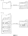
- Fig. 2 illustrates block diagrams 202-204 of a system for managing and optimizing a communication system in accordance with various aspects provided herein.
- the system can include a UE 210 and a network manager 220. While only one UE 210 and network manager 220 are illustrated in Fig. 2 , it should be appreciated that the system illustrated by diagrams 202-204 can include any number of UEs 210 and/or network managers 220.
- network manager 220 can be any appropriate network entity, such as a Mobility Management Entity (MME), a network controller, a network management server, or the like.
- MME Mobility Management Entity
- network manager 220 can utilize information relating to one or more UEs 210 in the network to optimize network performance.
- a network manager would rely on manually obtained and communicated measurements from devices in the network to optimize network performance. These measurements can be obtained through drive testing and/or other manual testing procedures within the network. However, such procedures can be costly and time-consuming, which can render such procedures undesirable and infeasible to implement for a rapidly-changing network.
- network manager 220 as illustrated by Fig. 2 can utilize a Self-Organized Network (SON) policy to standardize and automate the performance and/or reporting of measurements by UEs 210, thereby enabling collection of information and/or optimization based on collected information to be conducted in an automatic and autonomous manner.
- SON Self-Organized Network
- network manager 220 can create and/or otherwise identify a SON policy (e.g ., a SON policy stored by a policy store 222) to be used within a network associated with network manager 220.
- the SON policy can specify standardized events to be reported by a UE 210, techniques for measuring and/or logging such events, techniques for reporting logged events to network manager 220, or the like.
- network manager 220 can facilitate autonomous management of the network.
- network manager 220 can provide a UE 210 in network with a SON policy to be used for detecting, logging, and reporting standardized events as illustrated by diagram 202.
- network manager 220 can initiate paging for UE 210.
- UE 210 can inform network manager 220 of its capability to support a SON policy (using, for example, a SON bearer and/or an associated network management protocol to be utilized with the SON policy) during an Attach procedure and/or another suitable procedure for establishing a connection between UE 210 and a network associated with network manager 220.
- UE 210 when UE 210 is initially attached via GSM EDGE (Enhanced Data rates for GSM Evolution) Radio Access Network (GERAN) and/or UMTS Terrestrial Radio Access Network (UTRAN) then subsequently moves to an Evolved UTRAN (E-UTRAN), UE 210 can provide an inter-system Tracking Area Update (TAU) message that includes SON-related UE capability information.
- GSM EDGE Enhanced Data rates for GSM Evolution
- GERAN Enhanced Data rates for GSM Evolution Radio Access Network
- UTRAN UMTS Terrestrial Radio Access Network
- UE 210 can provide an inter-system Tracking Area Update (TAU) message that includes SON-related UE capability information.
- TAU Tracking Area Update
- a list of UEs 210 with SON capability can be gathered and maintained by network manager 220.
- UE 210 can operate according to the SON policy 212 as illustrated by diagram 204.
- UE 210 can include an event detector 214 to detect the occurrence of one or more standardized events defined in the SON policy 212, an event logger to log detected events and/or perform corresponding measurements in accordance with the SON policy 212, a log reporter 218 to report information relating to detected events to network manager 220 and/or another suitable entity according to a schedule provided in the SON policy 212, and/or other appropriate mechanisms for carrying out the SON policy 212.
- network manager 220 can utilize a network optimizer module 224 and/or any other appropriate means upon receiving reports of logged events from UE 210 to optimize the performance of the network based on the received reports without requiring manual testing or measurements.
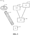
- a diagram 300 is provided that illustrates an example implementation of a Self Organized Network in accordance with various aspects.
- a UE 310 can interact with a network that includes a MME 320, a gateway (GW) 330, an eNB 340, a SON server 350, and/or any other suitable entities.
- MME 320 can track movement of a UE 310 throughout the network, initiate paging for UE 310, and/or perform other suitable actions.
- GW 330 can serve as a connecting point between UE 310 and one or more data networks with which UE 310 can communicate.
- GW 330 can route data between one or more data networks and UE 310.
- eNB 340 can provide basic communication functionality for UE 310 by, for example, scheduling resources to be used for transmission by UE 310, performing power control for UE 310, acting as a liaison between UE 310 and other entities in the network (e.g ., MME 320, GW 330, or the like), and/or performing other appropriate actions.
- SON server 350 can be utilized to implement self-organized network management within the network illustrated by diagram 300.
- SON server 350 can specify all or part of a SON policy to be utilized by UE 310 (e.g ., standardized events, techniques for logging events, techniques for reporting events, etc .).
- SON server 350 can be implemented in conjunction with an operations and management (O&M) system within the network illustrated by diagram 300.
- O&M operations and management
- SON server 350 can maintain a list of UEs 310 in an associated network that have SON capability.
- SON server 350 can relay information relating to a SON policy for UE 310 and/or other information to UE 310 via a SON bearer 352.
- SON bearer 352 can be provided as a direct logical interface between UE 310 and SON server 350.
- SON bearer 352 can also be utilized by UE 310 to relay event reports and/or other suitable information back to SON server 350.
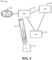
- the network illustrated by diagram 400 can include a UE 410, a MME 420, a GW 430, an eNB 440, and/or a SON server 450, which can perform in a similar manner to the corresponding entities in the network illustrated by diagram 300.
- MME 420 can interface with SON server 450 via any suitable wired and/or wireless communication method to obtain SON policy information from SON server 450, which can subsequently be relayed to UE 410 via a SON bearer 452 between MME 420 and UE 410.
- UE 410 can provide information relating to events logged according to the SON policy and/or other suitable information to MME 420 via the SON bearer 452. Upon receiving such information, the information can be relayed by MME 420 to SON server 450.
- SON bearer 452 can be implemented as a control plane-based bearer using Non-Access Stratum (NAS) signaling between UE 410 and MME 420.
- NAS Non-Access Stratum
- a control plane-based SON bearer 452 can be implemented by modifying a protocol stack utilized by the network illustrated by diagram 400 to include a protocol for network management signaling.
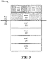
- An example of a protocol stack that can be utilized for this purpose is illustrated by diagram 500 in Fig. 5 .
- a protocol stack utilized by a network can include one or more NAS signaling protocols 502 and/or one or more Access Stratum (AS) signaling protocols 504.
- NAS signaling protocols 502 can include, for example, an EPS (Evolved Packet System) Session Management (ESM) protocol 512 and/or an EPS Mobility Management (EMM) protocol 520.
- EMM Evolved Packet System
- EMM EPS Mobility Management
- AS signaling protocols 504 can include, for example, a Radio Resource Control (RRC) protocol 530, a Radio Link Control (RLC) protocol 540, a Media Access Control (MAC) protocol 550, and/or a Physical Layer (PHY) protocol 560.
- RRC Radio Resource Control
- RLC Radio Link Control
- MAC Media Access Control
- PHY Physical Layer
- a protocol stack can be extended to include an EPS Network Management (ENM) protocol 512, which can be utilized to exchange SON related information between a UE and MME (e.g ., to implement SON bearer 452 between UE 410 and MME 420).
- ENM EPS Network Management
- the ENM protocol 512 can be defined to reside above and utilize existing functions of the EMM protocol 520 in a similar manner to the ESM protocol 514.
- a SON bearer can be implemented as a user plane-based bearer between a UE and a Packet Data Network (PDN) GW.
- PDN Packet Data Network
- This can be implemented by, for example, utilizing an Internet Protocol (IP) bearer between the UE and PDN GW such that interaction between the UE and the SON server is regarded as an IP application function.
- IP Internet Protocol
- a PDN GW in such an implementation can coordinate with one or more other GW nodes to provide SON functionality for a UE that leaves the local area associated with the PDN GW.
- one or more security measures can be implemented between the UE and the SON server to secure communication between the UE and SON server via the PDN GW.
- one or more specifications generally known in the art such as the Open Mobile Alliance (OMA) Device Management (DM) specification and/or any other suitable specification, can be utilized to set up and/or maintain a user plane bearer between a UE and a PDN GW and/or another suitable network entity.
- OMA Open Mobile Alliance
- DM Device Management
- a network device e.g ., a UE 210 to log and report network events in accordance with a SON policy are illustrated. It can be appreciated that a network device can, in accordance with various aspects described herein, utilize one or more of the illustrated systems and/or any other suitable system(s) to facilitate operation according to a SON policy.
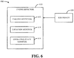
- system 600 can include an event detector 610, which can detect one or more events that occur in an associated network.
- events can be defined by a SON policy 620 and/or another suitable set of definitions.
- event detector 610 can be associated with a device in a network ( e.g ., UE 210), or alternatively event detector 610 can be a stand-alone entity in a communication network.
- event detector 610 can include one or more modules 612-616 for facilitating detection of various types of events.
- event detector 610 can include a failure detector 612 for detecting failures associated with a network and/or devices in a network, such as radio link failures, connection failures, hardware failures, or the like.
- event detector 610 can include a location monitor 614, which can monitor the location of system 600 and/or an associated device within a network and any changes to the monitored location ( e.g ., movement of an associated device between cells and/or networks).
- Event detector 610 can additionally and/or alternatively include an operating state monitor 616, which can monitor transmission resources (e.g ., resources in frequency, code, etc .), transmit power, observed interference, and/or other operation parameters associated with a network device and/or changes to such parameters.
- transmission resources e.g ., resources in frequency, code, etc .
- logging can be triggered for the detected event.
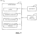
- a system 700 for logging a detected event is illustrated by Fig. 7 .
- system 700 can include an event logger 710, which can measure and/or otherwise obtain information relating to the state of an associated device and/or network upon the occurrence of an event detected by event detector 730.
- events identified by event detector 730 can be based on a list of standardized events provided by SON policy 720 and/or another suitable set of event definitions.
- event detector 710 can include one or more modules 712-718 for performing various measurements and/or observations associated with the operating state of an associated device and/or network at or near (e.g ., preceding and/or following) the time of an event.
- event logger 710 can include a clock 712 for determining the time of an event and generating timestamp information and/or other related information; a resource analyzer 714 for determining transmission resources, power settings, or the like, that are used by an associated device at or near the time of an event; a cell state monitor 716 for determining a serving cell for an associated device at the time of an event, a prior and/or target cell or network in the case of an associated device moving from one cell and/or network to another cell and/or network, or any other suitable information; a channel measurement module 718 for determining signal quality, observed interference, and/or other channel measurements at the time of an event and/or a time preceding or following an event; and/or any other suitable module.
- a clock 712 for determining the time of an event and generating timestamp information and/or other related information
- a resource analyzer 714 for determining transmission resources, power settings, or the like, that are used by an associated device at or near the time of an event
- event logger 710 can utilize information measured and/or otherwise obtained in association with an event to generate a report corresponding to the event.
- event logger 710 can generate a report for a radio link failure (RLF) event that includes a timestamp corresponding to a time of the event, position information for an associated device if available, an identity of a current serving cell for the associated device, identities of one or more target cells to be utilized in the case of connection re-establishment in one or more frequencies or radio access technologies (RATs), channel measurements for a predetermined period of time prior to the RLF event, and/or other suitable information.
- RLF radio link failure
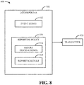
- system 800 can include a log reporter 810, which can facilitate reporting of one or more event logs 812 generated in accordance with a reporting policy 814 to one or more network entities via a transmitter 820 and/or other suitable means.
- reporting policy 814 can be implemented based on a SON policy (e.g ., SON policy 212), which can be provided to log reporter 810 and/or a device associated with log reporter 810.
- reporting policy 814 can specify one or more details regarding the manner in which event log(s) 812 are to be reported to the network.
- reporting policy 814 can include a list of report destinations 816, which can specify network entities to which log reporter 810 is instructed to provide event log(s) 812.
- Report destinations 816 can include, for example, a SON server, a network gateway, an eNB, a MME, and/or any other suitable entity.
- the list of report destinations 816 can specify a single destination, based on which log reporter 810 can provide reports ( e.g ., over a SON bearer 352 and/or 452) to the specified destination. Subsequently, the destination entity can provide reports to other network entities via backhaul communication or the like as necessary within the network.
- reporting policy 814 can include a reporting schedule 818, which can specify one or more instances in time at which reports are to be provided by log reporter 810. For example, reports can be scheduled to occur at regularly scheduled intervals, such as regular time intervals (e.g ., once per day, once per hour, etc .) or time intervals based on normal network loading patterns ( e.g ., during periods of relatively low network loading, such as late night or early morning). Alternatively, reporting schedule 818 can specify that reporting is to occur at irregular intervals.
- reporting schedule 818 can provide for reporting of event log(s) 812 in response to paging requests from the network, following events that trigger the generation of corresponding event logs 812, open explicit requests for reporting by one or more destination network entities, or the like.
- reports can be scheduled to occur when a register and/or other memory at the UE configured for storing measurement logs becomes full or nearly full.
- system 900 can include a UE 910, which can communicate with a base station 920. While only one UE 910 and one base station 920 are illustrated in system 900, it should be appreciated that system 900 can include any suitable number of UEs 910 and/or base stations 920. Further, it should be appreciated that UEs 910 and/or base stations 920 in system 900 can communicate with any other suitable entities in system 900 not illustrated by Fig. 9 .
- system 900 can further include a core network 940 that can include a MME (e.g ., MME 320 or 420), a SON server (e.g ., SON server 350 or 450), an operations and management (O&M) entity, and/or one or more other entities to facilitate self-optimization and/or self-healing of system 900 as generally described herein.
- MME e.g ., MME 320 or 420
- a SON server e.g ., SON server 350 or 450
- O&M operations and management
- UE 910 can include a RLF detector 912, which can be used to detect RLF events such as, for example, dropped calls, handover failures, failures to establish new calls, or the like.
- UE 910 can further include a location estimator 914 that can determine the location of UE 910 at the time of a detected failure and generate corresponding location information.
- Location estimator 914 can employ one or more techniques for determining location of UE 910, which can include, but are not limited to, satellite-based technology (e.g ., global positioning system (GPS)), network-based mechanisms, a hybrid of network-based and satellite-based mechanisms, and/or any other technique(s).
- UE 910 can include a RLF register 916, which can be utilized to retain information relating to one or more failure events and corresponding location information.
- base station 920 (and/or one or more entities in core network 940) can include a RLF detector 922, which can detect radio link failures with at least one mobile device such as UE 910.
- Base station 920 can further include a location estimator 924 that can facilitate determining location information associated with at least one mobile device upon detection of a RLF event.
- an aggregation module 926 at base station 920 can aggregate event and/or location information generated at base station 920 corresponding to a given RLF event with information related to the RLF event received from one or more UEs 910.
- Information generated by RLF detector 922 and/or location estimator 924, and/or information aggregated by aggregation module 926, can subsequently be stored at a RLF register 928.
- base station 920 can further include an optimization analysis module 930 that can determine if network optimization(s) would be beneficial to one or more mobile devices in a serving area of base station 920. For example, optimization analysis module 930 can determine if a neighbor list associated with base station 920 should be optimized, calculate the benefit of adding a new base station (e.g ., due to RLF events caused by lack of network capacity) and/or repeater ( e.g ., due to RLF events caused by poor signal quality), and/or perform other suitable actions.
- base station 920 can include a reporting module 932 that can report aggregated event and location information stored by RLF register 928 and/or optimization analysis results generated by optimization analysis module 930 to core network 940 to facilitate network optimization and planning.
- modules 922-932 can be located at and/or otherwise associated with base station 920.
- said modules 922-932 could additionally or alternatively be implemented by one or more nodes in core network 940 (e.g., a SON server, an O&M entity, and/or any other suitable core network node).
- optimization analysis module 930 can be associated with one or more entities in core network 940 and can operate on information obtained from UEs 910 and/or base stations 920.
- UE 910 and base station 920 can cooperate to detect and report information relating to one or more RLF events. More particularly, UE 910 (via RLF detector 912 and/or location estimator 914) and/or base station 920 ( via RLF detector 922 and/or location estimator 924) can cooperatively record information relating to an RLF event and provide recorded information to core network 940 in varying degrees.
- a UE 910 upon detecting a RLF event, can be configured to record all information relating to the event, such as a timestamp of the RLF event, position of UE 910 if available, the identity of a serving cell, the identity of a target cell in cases involving radio link re-establishment, a target inter-radio access technology (RAT) or inter-frequency cell in cases where UE 910 re-enters the service area in another RAT and/or frequency, channel measurements prior to failure, or the like.
- RAT inter-radio access technology
- the time at which the target cell is accessed at the new RAT and/or frequency can additionally be recorded.
- Such information, and/or any other suitable information can then be submitted to base station 920 ( e.g ., for processing by optimization and analysis module 930) and/or one or more entities in core network 940. Accordingly, in such an example, network self-optimization can be performed based on control plane signaling conducted with UE 910.
- UE 910 and base station 920 upon detecting a RLF event, can cooperatively record and report information associated with the RLF.
- UE 910 can record the time of the RLF event and the position of UE 910 at the time of the event, and base station 920 can record serving cell, target cell, and/or channel information in a similar manner to the measurements conducted by UE 910 as described in the first example above.
- base station 920 can record serving cell, target cell, and/or channel information in a similar manner to the measurements conducted by UE 910 as described in the first example above.
- the foregoing is merely one example of a division that can be implemented, and that UE 910 and base station 920 can record any suitable overlapping or non-overlapping sets of information.
- base station 920 Upon recordation, base station 920 (or one or more entities in core network 940) can aggregate its recorded information (e.g ., via aggregation module 928) with information relating to the event reported by a UE 910 involved in the event. Based on the aggregated information, optimizations can be performed via optimization and analysis module 930 and/or a report to core network 940 can be conducted via reporting module 932. In one example, base station 920 can perform measurements, analyze existing system settings related to UE 910, and/or perform any other suitable actions to obtain information for recording. Further, in the above example, it can be appreciated that network self-optimization can be performed based on a combination of user plane and control plane signaling conducted between UE 910, base station 920, and/or core network 940.
- base station 920 (or core network 940) can be configured to record all information relating to a RLF event involving one or more UEs 910.
- RLF detector 922 and/or location estimator 924 can be utilized to perform one or more measurements that are similar to those performed by UE 910 as described in the first example above.
- aggregation module 926 can be configured to obtain one or more timestamp reports and/or other RLF event reports from respective affected UEs 910, which can be utilized by base station 920 to augment and/or confirm its recorded information. Accordingly, in such an example, it can be appreciated that network self-optimization can be performed based on IP signaling between base station 920 and core network 940 and/or user plane signaling for UE 910.
- a reporting module 918 at UE 910 can generate a report of one or more RLF events based on data retained by RLF register 916.
- reporting module 918 can provide event information to base station 920, core network 940, and/or any other suitable entity. Further, such information can be provided upon request by base station 920 or one or more entities in core network 940 (e.g ., an O&M center, a SON server, etc .), on a periodic basis, upon triggering of one or more predefined events (e.g ., RLF register 918 becoming full, the associated radio link becoming operational, etc .), and/or at any other suitable time.
- predefined events e.g ., RLF register 918 becoming full, the associated radio link becoming operational, etc .
- UE 910 and/or base station 920 can be configured to provide periodic reports to each other and/or to core network 940 based on a variable reporting period.
- a period at which UE 910 and/or base station 920 reports to core network 940, or a period at which UE 910 reports to base station 920 can be configured to be relatively short in length to require more reporting in times immediately following a change in network topology (e.g ., an added or removed base station, etc.) as compared to times more distant from changes in network topology.
- UE 910 can be configured to utilize one or more applications and/or other mechanisms by which reporting module 918 can tunnel and/or otherwise provide data directly to one or more entities in core network 940.
- a format that can be utilized by reporting module 918 and/or reporting module 932 for providing RLF reports is illustrated by diagram 1000 in Fig. 10 .
- a report can be provided in the form of a RLF message, which can include RLF event data 1002 followed by a last event bit 1004.
- last event bit 1004 can be utilized to identify whether additional RLF events are to be transmitted, thereby enabling a chain of RLF event reports to be communicated in a single transmission.
- last event bit 1004 can be set to '0' to indicate that no more RLF events follow or to '1' to indicate that additional RLF events are to follow.
- system 900 can, in accordance with one aspect, be utilized to facilitate RLF-based neighbor list optimization in a wireless communication network.
- NL neighbor list
- SON existing network implementations provide for standardized optimizations of network planning based on events such as call drops, handover failure, new call establishment failure, or the like.
- network optimization can be performed periodically with other input parameters such as distance between two base stations, signal strength, planning tool data, and/or other parameters.
- the network will likely not be optimized even after neighbor list optimization as, for example, there may be a need for additional repeaters and/or base stations. Further, this need may not be readily recognizable during RLF-based NL optimization due to the fact that a network may still attempt to create a new NL from existing cells and/or sectors. If a drive test is performed to verify a good radio link, it can be appreciated that there still is a probability of a suboptimal network NL, as the network optimization is based on a drive test conducted on fixed drive routes while the network as a whole extends beyond the drive routes. Accordingly, radio link issues in these areas are generally not discovered, and as a consequence the network is generally not optimized in these areas.
- the optimized NL list may not be optimal, which can in turn lead to a requirement for second, third, etc ., rounds of optimization around the same geography. In some cases, these problems can continue until a new base station or repeater is introduced.
- system 900 can enable a UE 910 to report a RLF event to an associated network (e.g ., via a base station 920 and/or core network 940) along with the reason for the failure and/or the location of the failure.
- Base station 920 and/or core network 940 can then use this information with other network planning and optimizing information to optimize an associated neighbor list, either among existing base stations or with deployment of one or more new base stations and/or repeaters.
- system 900 offers robustness to an associated network as a UE 910 is able to report a RLF to the network with a failure reason and a failure location throughout the entire network without being limited to drive routes, thereby enabling the entire network to be optimized.
- system 900 can operate in various manners depending on the capabilities of UE 910. More particularly, in a first specific example, UE 910 can be equipped with support for reporting location (e.g ., using Assisted GPS (A-GPS), Advanced Forward Link Trilateration (AFLT), etc .) and a register that keeps record of the location of UE 910 and one or more RLF events. In such an example, when the radio link associated with UE 910 fails causing a call drop, a handover failure, or a failure to establish a new call, UE 910 can record the event in a register. Next, UE 910 can trigger a location estimation of itself using a satellite-based, network-based, and/or hybrid technology.
- A-GPS Assisted GPS
- AFLT Advanced Forward Link Trilateration
- UE 910 can keep its location and the RLF event in a register and subsequently transfer such information to base station 920.
- base station 920 can determine whether an immediate change in an associated neighbor list will help UEs in the area of UE 910. The result of this determination can then be provided to core network 940 for further network organization and planning.
- UE 910 can be equipped with support for reporting location (e.g ., using A-GPS, AFLT, etc .), a register that keeps record of the location of UE 910 and one or more RLF events, and a timer that starts at a first RLF event and restarts at consecutive RLF events.
- UE 910 upon experiencing a RLF event, can record the event and estimate location as described above.
- UE 910 can start a timer that continues until another RLF event occurs.
- UE 910 can place the location and cause of the previous failure in a buffer for transmission to base station 920. This process can subsequently be repeated until UE 910 establishes a sufficient communication link with base station 920, at which time UE 910 can report information corresponding to the recorded RLF event(s) to base station 920.
- UE 910 can be equipped with support for reporting location (e.g ., using A-GPS, AFLT, etc .), a register that keeps record of the location of UE 910, and base station 920 can be equipped with a register that keeps record of one or more RLF events and their corresponding causes.
- base station 920 upon encountering a RLF failure, can record the event in a register.
- UE 910 can estimate its location as generally described above. Once a communication link has been established between UE 910 and base station 920, UE 910 can transfer the estimated location information to base station 920, which can subsequently perform neighbor list optimization as generally described above.
- FIGs. 11-15 various procedures that can be implemented in accordance with various aspects described herein are illustrated. It should be appreciated, however, that the procedures illustrated by Figs. 11-13 are provided as non-limiting examples and that any suitable procedures could be utilized in addition to, or in place of, the illustrated procedures. It should be further appreciated that any procedures that could be utilized as described herein are intended to fall within the scope of the hereto appended claims.
- a diagram 1100 that illustrates a procedure for providing a network management policy (e.g ., SON policy 212) to a device (e.g ., UE 210) is provided.
- a network management policy e.g ., SON policy 212
- a device e.g ., UE 210
- the procedure illustrated by diagram 1100 can be utilized for providing a UE with a network management policy during an attach procedure utilized by the UE for establishing communication with an associated network.
- a UE can initiate an attach procedure with a network by communicating an Attach Request message to the EMM layer of a MME associated with the network.
- the Attach Request message provided by the UE at time 1102 can indicate the capability of the UE and/or network (NW) in terms of SON and/or ENM support to the network.
- NW network
- a notification of the capability of the UE and network for SON support can be relayed from the EMM layer at the MME to the ENM layer. This notification can in turn be provided to a SON server with the ID of the UE at time 1106.
- the SON server can relay a SON policy for the UE and network to the ENM layer of the MME.
- the ENM layer at the MME can provide an ENM SON Policy Setup Request for the UE to the EMM layer along with the SON policy configured for the UE by the SON server at time 1112.
- the SON policy can subsequently be relayed to the UE by the EMM layer at the MME at time 1114 using a combined Attach Accept and ENM SON Policy Setup Request message to the UE.
- the UE can provide an Attach Complete and ENM SON Policy Setup Response message at time 1116 to acknowledge completion of the attach procedure and confirm receipt of the SON policy.
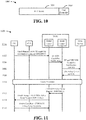
- FIG. 12 a diagram 1200 that illustrates another procedure for providing a network management policy to a network device is illustrated.
- an MME can convey a SON policy to a UE after a signaling connection between the UE and the network associated with the MME establish a signaling connection.
- the procedure illustrated by diagram 1200 can begin at time 1202, wherein a SON server associated with the network provides a SON policy to be utilized by a UE to an associated MME.
- this SON policy can then be provided by the MME to a UE.
- the MME can page the UE to set up a signaling connection for an ENM message exchange.
- the MME can provide a Paging Request message to an eNB serving the UE, which in turn can page the UE at time 1206.
- the UE can respond to the paging signal received at time 1204 by submitting a Service Request message to the MME.
- the MME can provide initial UE context to the eNB.
- the UE context provided at time 1210 can omit user plane context.
- the eNB can utilize this information to engage in a Signaling Radio Bearer (SRB) setup process with the UE at time 1212, after which the eNB can provide an Initial UE Context Response message to the MME at time 1214.
- SRB Signaling Radio Bearer
- a signaling bearer can be established between the UE and MME.
- the MME can provide an ENM SON Policy Setup Request message to the UE at time 1218.
- this message can specify one or more details of the SON policy to be utilized by UE (e.g ., definitions of events to report, measurements to include in reports, schedules for reporting, etc.).
- the UE can acknowledge the SON policy provided by the MME at time 1218 with an ENM SON Policy Setup Response message communicated to the MME.
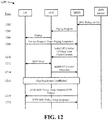
- a diagram 1300 is provided that illustrates an example procedure that can be utilized for providing reports according to a network management policy in accordance with various aspects.
- an MME associated with the network can page the UE to set up a signaling connection for an ENM message exchange.
- paging can occur at times 1302 through 1316 in a similar manner to the procedure illustrated by diagram 1200 at times 1202-1216.
- the procedure illustrated by diagram 1300 can be initiated in any suitable manner, such as by the UE itself based on its SON policy.
- the MME can submit an ENM SON Logged Event Report Request message to the UE at time 1318.
- the UE can communicate an ENM SON Logged Event Report back to the MME at time 1320 that includes one or more requested event logs.
- a report of the logged event can then be provided from the MME to the SON server at time 1322.
- the report request provided to the UE at time 1318 can specify reporting of one or more specific event logs, which can be provided from the UE to the MME at time 1320.
- the report request can more generally request reporting of some or all event logs maintained by the UE in a predetermined time period ( e.g ., since the last report by the UE).
- the report request can additionally specify one or more specific items to be included in the event log(s) that are provided by the UE at time 1320.
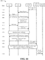
- a diagram 1400 is provided that illustrates an example procedure for providing a RLF report to an O&M entity (e.g ., associated with a core network 940).
- a signaling bearer can be established between a UE and an MME at times 1402-1416 in a similar manner to that illustrated by diagram 1200 at times 1202-1216.
- a logged event report can be provided by the UE to a SON server via the MME at times 1418-1422 in a similar manner to the procedure illustrated by diagram 1300 at times 1318-1322.
- the network can trigger co-relation of multiple RLF events at the UE and the network at the SON server at time 1424. Subsequently, at time 1426, the SON server can report the RLF events in a message to an O&M entity on a periodic basis to evaluate the need for another eNB and/or repeater, perform neighbor list optimization, and/or conduct any other suitable action(s).
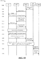
- FIG. 15 another diagram 1500 is provided that illustrates an example procedure for providing an on-demand RLF report to an O&M entity.
- a signaling bearer can be established between a UE and a MME, based on which the UE can submit a logged event report to a SON server via the MME, at times 1502-1522.
- the network can trigger co-relation of multiple RLF events at the UE and the network at the SON server in a similar manner to that illustrated in diagram 1400 at time 1424.
- an O&M entity can utilize request messages to the SON server and response messages from the SON server, respectively, to evaluate the need for another eNB and/or repeater, perform neighbor list optimization, and/or conduct any other suitable action(s).
- an example network can include one or more operating base stations 1602, which can provide coverage for respective service areas.
- a first grouping 1608 represents mobile device locations associated with failure to originate new calls
- a second grouping 1610 represents mobile device locations associated with dropped calls
- a third grouping 1612 represents mobile device locations associated with handover failures, and so on.
- information relating to groupings 1608-1612 can be utilized as the basis for a determination that a new base station 1606 and/or a new repeater 1604 are needed in the network.
- FIG. 17-22 methodologies that can be performed in accordance with various aspects set forth herein are illustrated. While, for purposes of simplicity of explanation, the methodologies are shown and described as a series of acts, it is to be understood and appreciated that the methodologies are not limited by the order of acts, as some acts can, in accordance with one or more aspects, occur in different orders and/or concurrently with other acts from that shown and described herein. For example, those skilled in the art will understand and appreciate that a methodology could alternatively be represented as a series of interrelated states or events, such as in a state diagram. Moreover, not all illustrated acts may be required to implement a methodology in accordance with one or more aspects.
- methodology 1700 for providing an event reporting policy to a device (e.g., UE 210) in a communication system (e.g ., the system illustrated by diagrams 202-204). It is to be appreciated that methodology 1700 can be performed by, for example, a base station, a network controller (e.g ., network manager 220) and/or any other appropriate network entity.
- Methodology 1700 begins at block 1702, wherein a UE with network management reporting capability is identified.
- a UE can be identified at block 1702 based on control signaling provided by the UE and/or past communication with the UE. Additionally and/or alternatively, network management reporting ability of a UE can be inferred from a device ID and/or other characteristics of the UE, and/or by any other appropriate means.
- a reporting policy (e.g. , a SON policy 217) that includes definitions of events to report and a reporting schedule to be utilized by the UE identified at block 1702 is identified.
- events in the list of definitions can include one or more failure events (e.g ., hardware failure, connection failure, RLF, etc .), one or more resource measurements (e.g ., measurements of transmit power and/or other resources used by a UE), network topology information (e.g ., identities of cells to which a UE is connected, home and/or visiting cells for a UE, etc. ), or the like.
- the schedule can specify one or more times for reporting logs associated with defined events, such as predetermined time intervals, time intervals based on network loading, time periods immediately or substantially immediately following logging of respective events, or the like.
- the reporting schedule identified at block 1704 can further include one or more diagnostic measurements to be provided in respective reports.
- a link for communication of the reporting policy can be established between a designated network entity to the UE at block 1706.
- a reporting policy can be provided to a UE at block 1706 using control-plane signaling during the establishment of a connection between the UE and a network in which methodology 1700 is performed, which can be accomplished via an attach procedure, a paging procedure, and/or another suitable technique.
- a reporting policy can be provided to a UE at block 1706 at any other appropriate time.
- a gateway node and/or another suitable network entity can be designated at block 1706 to provide the reporting policy to the UE using a user-plane bearer between the designated network entity and the UE.
- a bearer can be established between a network entity designated at block 1706 and a UE such that the designated network entity and the UE can interact via one or more IP application functions.
- methodology 1700 can conclude.
- methodology 1700 can optionally proceed to block 1708, wherein one or more reports are received from the UE to which a link for providing the reporting policy was established at block 1706 according to said reporting policy.
- Methodology 1700 can then conclude at block 1710, wherein network performance is optimized based at least in part on report(s) received at block 1708. Optimization at block 1710 can include, for example, adjustments to rate, coding, power, and/or other parameters utilized for communication with the UE in order to reduce the occurrence of failures logged by the UE.
- optimization at block 1710 can include control of transmit power and/or resources in frequency, time, code, or the like in order to mitigate the effects of interference in a network in which methodology 1700 is performed.
- any other suitable optimizations could be performed at block 1710.
- Fig. 18 illustrates a methodology 1800 for managing a network reporting procedure.
- Methodology 1800 can be performed by, for example, an access point, a network management entity, and/or any other appropriate network device.
- Methodology 1800 begins at block 1802, wherein a reporting policy to be provided to a UE is identified.
- a paging procedure e.g ., a paging procedure as illustrated by diagram 1000
- methodology 1800 can proceed to block 1808, wherein the reporting policy identified at block 1802 is provided to the UE.
- paging at block 1806 and communication of a reporting policy at block 1808 can be combined into a single action upon determining at block 1804 that the UE is idle.
- methodology 1800 can proceed to block 1810, wherein a report to be provided by the UE according to the reporting policy is identified.
- a specific report can be identified at block 1810 that is to be provided by the UE according to the reporting policy provided to the UE at block 1808.
- the identification at block 1810 can be more generally directed to one or more reports that are logged and/or stored by the UE at the time of identification.
- Methodology 1800 can then proceed to block 1812, wherein it is determined whether the UE is idle. If the UE is idle, a paging procedure (e.g ., a paging procedure as illustrated by diagram 1100) can be utilized at block 1814 to page the UE.
- a paging procedure e.g ., a paging procedure as illustrated by diagram 1100
- methodology 1800 can proceed to block 1816, wherein the report(s) identified at block 1810 are requested from the UE.
- paging at block 1814 and request(s) made at block 1816 can be combined into a single action upon determining at block 1812 that the UE is idle.
- Methodology 1800 can then conclude at block 1818, wherein report(s) are obtained from the UE in response to the request(s) made at block 1816.
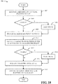
- Fig. 19 is a flow diagram of a methodology 1900 for logging and reporting a network event according to a network management scheme (e.g ., a SON policy 212).
- Methodology 1900 can be performed by, for example, a terminal device (e.g ., UE 210) and/or any other suitable network entity.
- Methodology 1900 begins at block 1902, wherein an event list and a reporting schedule are received from a network (e.g ., from a network manager 220 as a SON policy 212).
- an event list received at block 1902 can include one or more definitions of standardized events that are utilized within the network.
- a reporting schedule received at block 1902 can identify times at which reporting is to be conducted and/or information to be provided in reports.
- Monitoring at block 1904 can include, for example, determining whether failures occur (e.g ., by using a failure detector 612), obtaining location and/or network topology information ( e.g ., via a location monitor 614) and detecting changes thereto, identifying communication resources, transmit power, and/or other operating parameters of the device performing methodology 1900 ( e.g ., using an operating state monitor 616) and observing changes to such parameters, and/or any other suitable operations.
- it is determined whether an event has been detected e.g ., by an event detector 610) based on the monitoring at block 1904. If an event has not been detected, monitoring at block 1904 continues.
- methodology 1900 continues to block 1908, wherein information relating to the detected event is collected.
- information can include, for example, the time of the event (e.g ., as determined by a clock 712), resources in power, frequency, etc., used at the time of the event (e.g ., as measured by a resource analyzer 714), location and/or network topology information observed (e.g ., by a cell state monitor 716) at the time of the event, channel quality and/or other diagnostic information (e.g ., as measured by a channel measurement module 718), and/or any other suitable information.
- methodology 1900 can conclude at block 1910, wherein information collected at block 1908 is reported to the network (e.g ., by a log reporter 810) according to the reporting schedule received at block 1902.
- reports can be provided at block 1910 to one or more predetermined destinations (e.g ., report destinations 816) at one or more times specified by the reporting schedule (e.g ., report schedule 818).
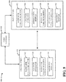
- Methodology 2000 begins at block 2002, wherein an event definition list and a set of associated measurements are received. At block 2004, the set of measurements received at block 2002 are performed. Next, at block 2006, it is determined whether an event defined in the event definition list has occurred. If such an event has not occurred, measurement at block 2004 continues. Alternatively, if it is determined at block 2006 that such an event has occurred, methodology 2000 continues to block 2008, wherein measurements that were made at block 2004 at the time of the event determined to have occurred at block 2006 are logged.
- methodology 2000 can proceed to block 2010, wherein it is determined whether log reporting has been requested by the network (e.g ., as illustrated by diagram 1100). If log reporting has been requested, methodology 2000 can conclude at block 2012, wherein the logged measurements are transmitted to the network in response to the request. In contrast, if log reporting has not been requested, methodology 2000 can instead proceed to block 2014 to determine whether a reporting schedule has been provided to the entity performing methodology 2000. If it is determined that a reporting schedule has been provided, methodology 2000 can conclude at block 2016, wherein the logged measurements are transmitted according to the provided reporting schedule. If, on the other hand, it is determined that a reporting schedule has not been provided, methodology 2000 can instead return to block 2010 to repeat the attempt to identify a request for log reporting.
- Fig. 21 illustrates a methodology 2100 for detecting and reporting a RLF event.
- Methodology 2100 can be performed by, for example, a terminal and/or any other appropriate network device.
- Methodology 2100 begins at block 2102, wherein a RLF is detected ( e.g ., by a RLF detector 912).
- Methodology 2100 can subsequently proceed to block 2104, wherein RLF event information and/or location information is recorded relating to the RLF detected at block 2102 ( e.g ., by a RLF detector or a location estimator 914, respectively).
- Methodology 2100 can then conclude at block 2106, wherein the event information recorded at block 2104 is transmitted ( e.g., via a reporting module 918).
- Methodology 2200 can be performed by, for example, a base station and/or any other suitable network device.
- Methodology 2200 can begin at block 2202, wherein a RLF is detected ( e.g ., by a RLF detector 922).
- Methodology 2200 can subsequently proceed to block 2204, wherein RLF event information and/or location information is recorded relating to the RLF detected at block 2202 ( e.g ., by a RLF detector 922 or a location estimator 924, respectively).
- Methodology 2200 can then proceed to block 2206, wherein information relating to the RLF detected at block 2202 is received from at least one mobile device (e.g ., UE 910).
- the information recorded at block 2204 and the information received at block 2206 are aggregated ( e.g ., by an aggregation module 926).
- Methodology 2200 can then conclude at block 2212, wherein the information aggregated at block 2210 is reported ( e.g ., via a reporting module 932).
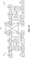
- system 2300 is a multiple-input multiple-output (MIMO) system that includes a transmitter system 2310 and a receiver system 2350.
- MIMO multiple-input multiple-output
- transmitter system 2310 and/or receiver system 2350 could also be applied to a multi-input single-output system wherein, for example, multiple transmit antennas ( e.g ., on a base station), can transmit one or more symbol streams to a single antenna device (e.g ., a mobile station).
- multiple transmit antennas e.g ., on a base station
- a single antenna device e.g ., a mobile station.
- aspects of transmitter system 2310 and/or receiver system 2350 described herein could be utilized in connection with a single output to single input antenna system.
- traffic data for a number of data streams are provided at transmitter system 2310 from a data source 2312 to a transmit (TX) data processor 2314.
- TX data processor 2314 can format, encode, and interleave traffic data for each data stream based on a particular coding scheme selected for each respective data stream in order to provide coded data.
- the coded data for each data stream can then be multiplexed with pilot data using OFDM techniques.
- the pilot data can be, for example, a known data pattern that is processed in a known manner. Further, the pilot data can be used at receiver system 2350 to estimate channel response.
- the multiplexed pilot and coded data for each data stream can be modulated (i.e ., symbol mapped) based on a particular modulation scheme (e.g ., BPSK, QSPK, M-PSK, or M-QAM) selected for each respective data stream in order to provide modulation symbols.
- a particular modulation scheme e.g ., BPSK, QSPK, M-PSK, or M-QAM
- data rate, coding, and modulation for each data stream can be determined by instructions performed on and/or provided by processor 2330.
- modulation symbols for all data streams can be provided to a TX processor 2320, which can further process the modulation symbols (e.g ., for OFDM).
- TX MIMO processor 2320 can then provides N T modulation symbol streams to N T transceivers 2322a through 2322t.
- each transceiver 2322 can receive and process a respective symbol stream to provide one or more analog signals.
- Each transceiver 2322 can then further condition (e.g ., amplify, filter, and upconvert) the analog signals to provide a modulated signal suitable for transmission over a MIMO channel.
- N T modulated signals from transceivers 2322a through 2322t can then be transmitted from N T antennas 2324a through 2324t, respectively.
- the transmitted modulated signals can be received at receiver system 2350 by N R antennas 2352a through 2352r.
- the received signal from each antenna 2352 can then be provided to respective transceivers 2354.
- each transceiver 2354 can condition (e.g ., filter, amplify, and downconvert) a respective received signal, digitize the conditioned signal to provide samples, and then processes the samples to provide a corresponding "received" symbol stream.
- An RX MIMO/data processor 2360 can then receive and process the N R received symbol streams from N R transceivers 2354 based on a particular receiver processing technique to provide N T "detected" symbol streams.
- each detected symbol stream can include symbols that are estimates of the modulation symbols transmitted for the corresponding data stream.
- RX processor 2360 can then process each symbol stream at least in part by demodulating, deinterleaving, and decoding each detected symbol stream to recover traffic data for a corresponding data stream.
- the processing by RX processor 2360 can be complementary to that performed by TX MIMO processor 2320 and TX data processor 2314 at transmitter system 2310.
- RX processor 2360 can additionally provide processed symbol streams to a data sink 2364.
- the channel response estimate generated by RX processor 2360 can be used to perform space/time processing at the receiver, adjust power levels, change modulation rates or schemes, and/or other appropriate actions. Additionally, RX processor 2360 can further estimate channel characteristics such as, for example, signal-to-noise-and-interference ratios (SNRs) of the detected symbol streams. RX processor 2360 can then provide estimated channel characteristics to a processor 2370. In one example, RX processor 2360 and/or processor 2370 can further derive an estimate of the "operating" SNR for the system. Processor 2370 can then provide channel state information (CSI), which can comprise information regarding the communication link and/or the received data stream. This information can include, for example, the operating SNR.
- CSI channel state information
- the CSI can then be processed by a TX data processor 2318, modulated by a modulator 2380, conditioned by transceivers 2354a through 2354r, and transmitted back to transmitter system 2310.
- a data source 2316 at receiver system 2350 can provide additional data to be processed by TX data processor 2318.
- the modulated signals from receiver system 2350 can then be received by antennas 2324, conditioned by transceivers 2322, demodulated by a demodulator 2340, and processed by a RX data processor 2342 to recover the CSI reported by receiver system 2350.
- the reported CSI can then be provided to processor 2330 and used to determine data rates as well as coding and modulation schemes to be used for one or more data streams. The determined coding and modulation schemes can then be provided to transceivers 2322 for quantization and/or use in later transmissions to receiver system 2350.
- the reported CSI can be used by processor 2330 to generate various controls for TX data processor 2314 and TX MIMO processor 2320.
- CSI and/or other information processed by RX data processor 2342 can be provided to a data sink 2344.
- processor 2330 at transmitter system 2310 and processor 2370 at receiver system 2350 direct operation at their respective systems.
- memory 2332 at transmitter system 2310 and memory 2372 at receiver system 2350 can provide storage for program codes and data used by processors 2330 and 2370, respectively.
- various processing techniques can be used to process the N R received signals to detect the N T transmitted symbol streams. These receiver processing techniques can include spatial and space-time receiver processing techniques, which can also be referred to as equalization techniques, and/or "successive nulling/equalization and interference cancellation" receiver processing techniques, which can also be referred to as “successive interference cancellation” or “successive cancellation” receiver processing techniques.
- Fig. 24 is a block diagram of a system 2400 that facilitates network management and optimization in accordance with various aspects described herein.
- system 2400 includes a base station or Node B 2402.
- Node B 2402 can receive signal(s) from one or more UEs 2404 via one or more receive (Rx) antennas 2406 and transmit to the one or more UEs 2404 via one or more transmit (Tx) antennas 2408.
- Rx receive
- Tx transmit
- Node B 2402 can comprise a receiver 2410 that receives information from receive antenna(s) 2406.
- the receiver 2410 can be operatively associated with a demodulator (Demod) 2412 that demodulates received information. Demodulated symbols can then be analyzed by a processor 2414.
- Processor 2414 can be coupled to memory 2416, which can store information related to code clusters, access terminal assignments, lookup tables related thereto, unique scrambling sequences, and/or other suitable types of information.
- Node B 2402 can employ processor 2414 to perform methodologies 1700, 1800, 2200, and/or other similar and appropriate methodologies.
- Node B 2402 can also include a modulator 2418 that can multiplex a signal for transmission by a transmitter 2420 through transmit antenna(s) 2408.
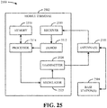
- Fig. 25 is a block diagram of a system 2500 that facilitates network event logging and reporting in accordance with various aspects described herein.
- system 2500 includes a mobile terminal 2502.
- mobile terminal 2502 can receive signal(s) from one or more base stations 2504 and transmit to the one or more base stations 2504 via one or more antennas 2508.
- mobile terminal 2502 can comprise a receiver 2510 that receives information from antenna(s) 2508.
- receiver 2510 can be operatively associated with a demodulator (Demod) 2512 that demodulates received information. Demodulated symbols can then be analyzed by a processor 2514.
- Processor 2514 can be coupled to memory 2516, which can store data and/or program codes related to mobile terminal 2502.
- mobile terminal 2502 can employ processor 2514 to perform methodologies 1900, 2000, 2100, and/or other similar and appropriate methodologies.
- Mobile terminal 2502 can also include a modulator 2518 that can multiplex a signal for transmission by a transmitter 2520 through antenna(s) 2508.
- Fig. 26 illustrates an apparatus 2600 that facilitates network management and optimization. It is to be appreciated that apparatus 2600 is represented as including functional blocks, which can be functional blocks that represent functions implemented by a processor, software, or combination thereof ( e.g ., firmware). Apparatus 2600 can be implemented in an access point (e.g ., eNB 340 and/or 440), a network controller (e.g ., MME 320 and/or 420, SON server 350 and/or 450, etc .) and/or any other appropriate network entity and can include a module 2602 for relaying a reporting policy to a terminal that includes a list of event definitions and measurements associated with the respective events and a module 2604 for performing network optimization based at least in part on reports received according to the reporting policy.
- an access point e.g ., eNB 340 and/or 440
- a network controller e.g ., MME 320 and/or 420, SON server 350 and/or 450, etc
- Fig. 27 illustrates another apparatus 2700 that facilitates network management and optimization in accordance with various aspects described herein. It is to be appreciated that apparatus 2700 is represented as including functional blocks, which can be functional blocks that represent functions implemented by a processor, software, or combination thereof ( e.g ., firmware). Apparatus 2700 can be implemented in a terminal device ( e.g ., UE 310 and/or 410) and/or any other appropriate network entity and can include a module 2702 for receiving a set of event definitions, a set of measurements, and a reporting schedule from a network; a module 2704 for logging measurements corresponding to the set of measurements upon occurrence of respective events; and a module 2706 for communicating the logged measurements to the network according to the reporting schedule.
- a terminal device e.g ., UE 310 and/or 410
- a module 2702 for receiving a set of event definitions, a set of measurements, and a reporting schedule from a network
- a module 2704 for logging measurements
- aspects described herein can be implemented by hardware, software, firmware, middleware, microcode, or any combination thereof.
- systems and/or methods are implemented in software, firmware, middleware or microcode, program code or code segments, they can be stored in a machine-readable medium, such as a storage component.
- a code segment can represent a procedure, a function, a subprogram, a program, a routine, a subroutine, a module, a software package, a class, or any combination of instructions, data structures, or program statements.
- a code segment can be coupled to another code segment or a hardware circuit by passing and/or receiving information, data, arguments, parameters, or memory contents. Information, arguments, parameters, data, etc. can be passed, forwarded, or transmitted using any suitable means including memory sharing, message passing, token passing, network transmission, etc.
- the techniques described herein can be implemented with modules (e.g ., procedures, functions, and so on) that perform the functions described herein.
- the software codes can be stored in memory units and executed by processors.
- the memory unit can be implemented within the processor or external to the processor, in which case it can be communicatively coupled to the processor via various means as is known in the art.
Claims (13)
- Procédé de consignation et de rapportage d'événements réseau par un équipement utilisateur (EU) dans un réseau LTE, comprenant :recevoir (2002) une messagerie basée sur un plan de contrôle d'un réseau qui configure l'EU pour consigner des résultats de mesures, dans lequel la messagerie basée sur un plan de contrôle est basée sur une pile de protocoles qui comprend un ou plusieurs protocoles de signalisation NAS, strate de non accès, et un ou plusieurs protocoles de signalisation AS, strate d'accès ;effectuer (2004) une ou plusieurs mesures ;consigner (2006) au moins l'une de l'une ou des plusieurs mesures sur la base de la configuration ;recevoir (2010) une requête explicite du réseau pour rapporter dans un journal de tous les journaux d'événements tenus à jour par l'EU dans une période de temps prédéterminée ; etrapporter (2012) les journaux d'événements au réseau en réponse à la requête.
- Procédé selon la revendication 1, dans lequel effectuer une ou plusieurs mesures comprend déterminer un ou plusieurs d'entre une heure d'un événement, l'emplacement réseau observé à une heure associée à un événement, ou des informations de canal à une heure associée à un événement.
- Procédé selon la revendication 2, dans lequel l'événement réseau comprend l'une d'entre une défaillance matérielle, une défaillance de connexion, une défaillance de liaison radio (RLF), un changement dans la topologie réseau observée et un changement dans les ressources de communication utilisées.
- Procédé selon la revendication 1, dans lequel le fait de consigner comprend stocker les mesures consignées dans une mémoire.
- Procédé selon la revendication 1, dans lequel le fait de recevoir comprend recevoir un ou plusieurs messages de radiomessagerie du réseau.
- Procédé selon la revendication 1, dans lequel le fait de rapporter comprend transmettre par tunnelisation l'une ou les plusieurs mesures à un serveur.
- Appareil de consignation et de rapportage d'événements réseau dans un réseau LTE, comprenant :un moyen pour recevoir (2702) une messagerie basée sur un plan de contrôle d'un réseau qui configure l'appareil pour consigner des résultats de mesures, dans lequel la messagerie basée sur un plan de contrôle est basée sur une pile de protocoles qui comprend un ou plusieurs protocoles de signalisation NAS, strate de non accès, et un ou plusieurs protocoles de signalisation AS, strate d'accès ;un moyen pour effectuer une ou plusieurs mesures ;un moyen pour consigner (216, 2704) au moins l'une de l'une ou des plusieurs mesures sur la base de la configuration ;un moyen pour recevoir une requête explicite du réseau pour rapporter dans un journal de tous les journaux d'événements tenus à jour par l'EU dans une période de temps prédéterminée ; etun moyen pour rapporter (218) les journaux d'événements au réseau en réponse à la requête.
- Appareil selon la revendication 7, dans lequel effectuer une ou plusieurs mesures comprend déterminer un ou plusieurs d'entre une heure d'un événement, l'emplacement réseau observé à une heure associée à un événement, ou des informations de canal à une heure associée à un événement.
- Appareil selon la revendication 8, dans lequel l'événement réseau comprend l'une d'entre une défaillance matérielle, une défaillance de connexion, une défaillance de liaison radio (RLF), un changement dans la topologie réseau observée et un changement dans les ressources de communication utilisées.
- Appareil selon la revendication 7, dans lequel le fait de consigner comprend stocker les mesures consignées dans une mémoire.
- Appareil selon la revendication 7, dans lequel le fait de recevoir comprend recevoir un ou plusieurs messages de radiomessagerie du réseau.
- Appareil selon la revendication 7, dans lequel le fait de rapporter comprend transmettre par tunnelisation l'une ou les plusieurs mesures à un serveur.
- Produit de programme informatique comprenant un support lisible par ordinateur ayant du code qui lorsque exécuté sur un ordinateur entreprend les étapes selon l'une quelconque des revendications 1-6.
Applications Claiming Priority (4)
| Application Number | Priority Date | Filing Date | Title |
|---|---|---|---|
| US3744308P | 2008-03-18 | 2008-03-18 | |
| US10902408P | 2008-10-28 | 2008-10-28 | |
| US12/403,925 US8780732B2 (en) | 2008-03-18 | 2009-03-13 | Method of network management by assistance from terminal using control-plane signaling between terminal and network |
| EP09721939.8A EP2258127B1 (fr) | 2008-03-18 | 2009-03-17 | Procédé de gestion de réseau par assistance depuis un terminal utilisant une signalisation de plan de commande entre le terminal et le réseau |
Related Parent Applications (2)
| Application Number | Title | Priority Date | Filing Date |
|---|---|---|---|
| EP09721939.8 Division | 2009-03-17 | ||
| EP09721939.8A Division EP2258127B1 (fr) | 2008-03-18 | 2009-03-17 | Procédé de gestion de réseau par assistance depuis un terminal utilisant une signalisation de plan de commande entre le terminal et le réseau |
Publications (2)
| Publication Number | Publication Date |
|---|---|
| EP2670184A1 EP2670184A1 (fr) | 2013-12-04 |
| EP2670184B1 true EP2670184B1 (fr) | 2017-11-08 |
Family
ID=40785528
Family Applications (2)
| Application Number | Title | Priority Date | Filing Date |
|---|---|---|---|
| EP09721939.8A Not-in-force EP2258127B1 (fr) | 2008-03-18 | 2009-03-17 | Procédé de gestion de réseau par assistance depuis un terminal utilisant une signalisation de plan de commande entre le terminal et le réseau |
| EP13181914.6A Active EP2670184B1 (fr) | 2008-03-18 | 2009-03-17 | Procédé de gestion de réseau par assistance depuis un terminal utilisant une signalisation de plan de commande et demandes du réseau au terminal |
Family Applications Before (1)
| Application Number | Title | Priority Date | Filing Date |
|---|---|---|---|
| EP09721939.8A Not-in-force EP2258127B1 (fr) | 2008-03-18 | 2009-03-17 | Procédé de gestion de réseau par assistance depuis un terminal utilisant une signalisation de plan de commande entre le terminal et le réseau |
Country Status (14)
| Country | Link |
|---|---|
| US (2) | US8780732B2 (fr) |
| EP (2) | EP2258127B1 (fr) |
| JP (2) | JP5832891B2 (fr) |
| KR (1) | KR101196627B1 (fr) |
| CN (2) | CN103561415B (fr) |
| AU (1) | AU2009225669B2 (fr) |
| CA (1) | CA2718945C (fr) |
| ES (1) | ES2657271T3 (fr) |
| HU (1) | HUE037707T2 (fr) |
| IL (1) | IL207855A0 (fr) |
| MX (1) | MX2010010108A (fr) |
| RU (1) | RU2488982C2 (fr) |
| TW (1) | TW201004402A (fr) |
| WO (1) | WO2009117443A1 (fr) |
Families Citing this family (129)
| Publication number | Priority date | Publication date | Assignee | Title |
|---|---|---|---|---|
| US8041656B2 (en) * | 2007-10-31 | 2011-10-18 | Alcatel Lucent | Method and apparatus for leveraging end user terminals in self-learning networks |
| CN101483639A (zh) * | 2008-01-11 | 2009-07-15 | 华为技术有限公司 | 一种网络中资源管理的方法 |
| US8780732B2 (en) | 2008-03-18 | 2014-07-15 | Qualcomm Incorporated | Method of network management by assistance from terminal using control-plane signaling between terminal and network |
| US8498207B2 (en) * | 2008-06-26 | 2013-07-30 | Reverb Networks | Dynamic load balancing |
| US8996016B2 (en) * | 2009-01-05 | 2015-03-31 | Google Technology Holdings LLC | Method for identifying user equipment to a femtocell |
| KR101652442B1 (ko) * | 2009-05-05 | 2016-08-30 | 엘지전자 주식회사 | 이동통신 네트워크 내에서 제어 평면(Control Plane)을 담당하는 서버 및 커넥션 설정을 제어하는 방법 |
| US9166875B2 (en) | 2009-06-22 | 2015-10-20 | Qualcomm Incorporated | Method and apparatus for network optimization using SON solutions |
| KR20110020161A (ko) * | 2009-08-21 | 2011-03-02 | 엘지전자 주식회사 | 이동통신 네트워크 내에서 제어 평면(Control Plane)을 담당하는 서버 및 SIPTO 기반의 세션을 제어하는 방법 |
| JP5878123B2 (ja) * | 2009-09-27 | 2016-03-08 | ゼットティーイー コーポレーションZte Corporation | 状態遷移方法及び装置 |
| WO2011039925A1 (fr) * | 2009-10-01 | 2011-04-07 | 日本電気株式会社 | Système de communication mobile, appareil station de base, appareil de commande, procédé de commande et support lisible par ordinateur |
| US9826416B2 (en) | 2009-10-16 | 2017-11-21 | Viavi Solutions, Inc. | Self-optimizing wireless network |
| US20110090820A1 (en) | 2009-10-16 | 2011-04-21 | Osama Hussein | Self-optimizing wireless network |
| US9288702B2 (en) * | 2009-10-30 | 2016-03-15 | Telefonaktiebolaget L M Ericsson (Publ) | User equipment reporting of connection loss |
| CN102056336B (zh) * | 2009-11-02 | 2013-01-09 | 华为技术有限公司 | 自组织操作的协调处理方法与装置、通信系统 |
| KR101449768B1 (ko) * | 2009-11-05 | 2014-10-14 | 에릭슨 엘지 주식회사 | Son을 위한 옥내용 기지국 구성 방법 및 그를 위한 이동통신 시스템 |
| KR101821264B1 (ko) | 2009-11-11 | 2018-01-24 | 삼성전자주식회사 | 이동통신시스템에서 복수개의 캐리어가 집적된 단말기의 라디오링크 실패 탐지 및 복구 방법 |
| US20120014308A1 (en) * | 2009-11-11 | 2012-01-19 | Samsung Electronics Co., Ltd. | Methods and apparatus to support reconfiguration in self organized wireless communications and networks |
| US8892101B2 (en) * | 2009-11-23 | 2014-11-18 | Nokia Corporation | Radio problem detection assisted rescue handover |
| US20110287793A1 (en) * | 2009-11-23 | 2011-11-24 | Qualcomm Incorporated | Providing configuration information for broadcast control of access terminal radio event handling |
| US8385900B2 (en) * | 2009-12-09 | 2013-02-26 | Reverb Networks | Self-optimizing networks for fixed wireless access |
| CN104540192B (zh) * | 2010-01-07 | 2019-02-01 | 日本电气株式会社 | 无线通信系统、无线终端、无线网络、无线通信方法 |
| KR20140021057A (ko) * | 2010-01-07 | 2014-02-19 | 닛본 덴끼 가부시끼가이샤 | 무선 통신 시스템, 무선 단말, 무선 기지국, 무선 통신 방법 및 프로그램 |
| JP2013516872A (ja) * | 2010-01-08 | 2013-05-13 | ノキア シーメンス ネットワークス オサケユキチュア | ネットワーク最適化 |
| WO2011093665A2 (fr) * | 2010-01-28 | 2011-08-04 | Lg Electronics Inc. | Procédé d'exécution de minimisation d'essai de fonctionnement/qualité (mdt) dans système de communication sans fil |
| KR101674221B1 (ko) * | 2010-01-28 | 2016-11-09 | 엘지전자 주식회사 | 무선 통신 시스템에서 로그된 측정 보고 방법 및 장치 |
| US8559336B2 (en) | 2010-01-29 | 2013-10-15 | Alcatel Lucent | Method and apparatus for hint-based discovery of path supporting infrastructure |
| US8868029B2 (en) * | 2010-01-29 | 2014-10-21 | Alcatel Lucent | Method and apparatus for managing mobile resource usage |
| US8542576B2 (en) * | 2010-01-29 | 2013-09-24 | Alcatel Lucent | Method and apparatus for auditing 4G mobility networks |
| US8493870B2 (en) * | 2010-01-29 | 2013-07-23 | Alcatel Lucent | Method and apparatus for tracing mobile sessions |
| US8767584B2 (en) * | 2010-01-29 | 2014-07-01 | Alcatel Lucent | Method and apparatus for analyzing mobile services delivery |
| KR101759366B1 (ko) | 2010-02-11 | 2017-07-31 | 엘지전자 주식회사 | 기지국과 중계 노드 사이의 백홀 링크 실패를 복구하는 방법 및 장치 |
| KR101829832B1 (ko) | 2010-03-26 | 2018-02-19 | 엘지전자 주식회사 | 무선 통신 시스템에서 신호 송수신 방법 및 이를 위한 장치 |
| JP5277199B2 (ja) * | 2010-04-05 | 2013-08-28 | 株式会社エヌ・ティ・ティ・ドコモ | 移動通信方法及び無線基地局 |
| US8995359B2 (en) | 2010-04-05 | 2015-03-31 | Qualcomm Incorporated | Method and apparatus to facilitate support for multi-radio coexistence |
| US8577360B2 (en) * | 2010-04-12 | 2013-11-05 | Telefonaktiebolaget Lm Ericsson (Publ) | UE-based MDT measuring and reporting in a cellular radio access network |
| CN102223665A (zh) * | 2010-04-19 | 2011-10-19 | 中兴通讯股份有限公司 | 无线链路失败rlf信息的处理方法及系统 |
| US8682310B2 (en) * | 2010-05-28 | 2014-03-25 | Telefonaktiebolaget L M Ericsson (Publ) | Network-based area positioning for capacity and coverage improvement |
| US8594657B2 (en) | 2010-06-15 | 2013-11-26 | Htc Corporation | Method for reporting MDT log and mobile communication device utilizing the same |
| US8571542B2 (en) * | 2010-06-21 | 2013-10-29 | Htc Corporation | Mobile communication device, service network, and methods for MDT log reporting |
| US8971848B2 (en) * | 2010-06-24 | 2015-03-03 | Telefonaktiebolaget L M Ericsson (Publ) | System and method for managing UE-based network performance measurements |
| JP5767449B2 (ja) | 2010-07-28 | 2015-08-19 | 京セラ株式会社 | 無線基地局及びその制御方法、無線端末、プロセッサ |
| EP2541983B1 (fr) | 2010-08-13 | 2016-03-30 | Kyocera Corporation | Procédé de collecte de mesures sans fil et terminal sans fil |
| TW201212585A (en) * | 2010-09-08 | 2012-03-16 | Htc Corp | Method of diagnostics and monitoring management and related communication device |
| CN102413494B (zh) * | 2010-09-21 | 2016-06-01 | 北京三星通信技术研究有限公司 | 一种检测无线链路失败或切换失败原因的方法 |
| KR20130081289A (ko) * | 2010-10-04 | 2013-07-16 | 교세라 가부시키가이샤 | 이동통신방법, 무선단말, 및 기지국 |
| US8724497B2 (en) * | 2010-11-03 | 2014-05-13 | Mediatek Inc. | Method of uplink MDT measurement |
| EP2648440A1 (fr) * | 2010-11-30 | 2013-10-09 | Fujitsu Limited | Procédé, dispositif terminal et station de base utilisés pour signaler une défaillance de liaison radio |
| US20120142337A1 (en) * | 2010-12-02 | 2012-06-07 | Jin Wang | Temporary activation of inter-rat features in base stations |
| US8909751B2 (en) * | 2010-12-28 | 2014-12-09 | Microsoft Corporation | Flexible policy based network decision making |
| US8700027B2 (en) * | 2011-02-11 | 2014-04-15 | Alcatel Lucent | Method and apparatus for network analysis |
| EP2487973A1 (fr) * | 2011-02-11 | 2012-08-15 | Alcatel Lucent | Notification à un équipement utilisateur dans un réseau mobile d'une requête de déclenchement d'application de l'équipement utilisateur d'un serveur d'application de réseau |
| KR101884348B1 (ko) * | 2011-03-30 | 2018-08-30 | 엘지전자 주식회사 | 이동통신 네트워크 내에서 제어 평면을 담당하는 서버에서 로컬 csg 제공 및 액세스 제어 방법 |
| US9167447B2 (en) | 2011-03-31 | 2015-10-20 | Mediatek Inc. | Failure event report for initial connection setup failure |
| US9661510B2 (en) * | 2012-03-30 | 2017-05-23 | Mediatek Inc. | Failure event report extension for inter-RAT radio link failure |
| US20120250498A1 (en) * | 2011-03-31 | 2012-10-04 | Mediatek, Inc. | Failure Event Report Correlation for Distributed RAN Self-Organization |
| CN103444223A (zh) * | 2011-04-04 | 2013-12-11 | 瑞典爱立信有限公司 | 限制异类无线通信系统中的干扰 |
| ES2754035T3 (es) | 2011-04-05 | 2020-04-15 | Samsung Electronics Co Ltd | Activación eficiente de portadoras en sistemas de comunicación inalámbrica basados en agregación de portadoras |
| KR101929307B1 (ko) | 2011-04-11 | 2018-12-17 | 삼성전자 주식회사 | Csg 셀에서 단말이 셀 재선택 우선 순위를 효율적으로 제어하는 방법 및 장치 |
| KR20120115953A (ko) * | 2011-04-11 | 2012-10-19 | 삼성전자주식회사 | 단말 획득 정보를 효율적으로 기지국에 전달하는 방법 및 장치 |
| US20130286851A1 (en) * | 2011-04-12 | 2013-10-31 | Public Wireless, Inc. | Common radio element application manager for wireless small cells |
| WO2012139798A1 (fr) * | 2011-04-15 | 2012-10-18 | Telefonaktiebolaget L M Ericsson (Publ) | Procédés et dispositifs de surveillance de liaison radio |
| KR101796271B1 (ko) * | 2011-04-27 | 2017-11-10 | 주식회사 팬택 | 무선 링크 실패 보고 장치 및 방법 |
| EP2706677B1 (fr) | 2011-05-03 | 2016-08-10 | Samsung Electronics Co., Ltd. | Procédé et appareil pour qu'un équipement d'utilisateur recevant un service mbms traite une programmation semi-permanente de sous-trame mbsfn dans un système de communication sans fil |
| EP2709406B1 (fr) | 2011-05-10 | 2020-07-22 | Samsung Electronics Co., Ltd. | Procédé et appareil de sélection de cellule dans un système de communication sans fil |
| KR101898109B1 (ko) | 2011-05-10 | 2018-09-13 | 삼성전자 주식회사 | 무선통신시스템에서 셀 선택 방법 및 장치 |
| US8509762B2 (en) | 2011-05-20 | 2013-08-13 | ReVerb Networks, Inc. | Methods and apparatus for underperforming cell detection and recovery in a wireless network |
| WO2012166032A1 (fr) * | 2011-06-01 | 2012-12-06 | Telefonaktiebolaget L M Ericsson (Publ) | Procédé, nœud et système de gestion d'un réseau mobile |
| KR20140044355A (ko) * | 2011-06-01 | 2014-04-14 | 가부시키가이샤 엔티티 도코모 | 소형 노드 디바이스들을 이용한 모바일 통신에서의 향상된 로컬 액세스 |
| GB2492364B (en) * | 2011-06-29 | 2016-03-30 | Fujitsu Ltd | Re-selecting network parameters in a cellular wireless network |
| EP2754271B1 (fr) | 2011-09-09 | 2019-11-13 | Reverb Networks Inc. | Procédés et appareil pour mettre en oeuvre un gestionnaire de réseaux à optimisation-organisation automatique |
| WO2013045537A1 (fr) * | 2011-09-30 | 2013-04-04 | Nokia Siemens Networks Oy | Filtrage de rapport de panne de liaison hertzienne |
| WO2013046185A2 (fr) * | 2011-09-30 | 2013-04-04 | Nokia Siemens Networks Oy | Réduction de trafic de gestion de défaillance dans des réseaux hétérogènes |
| US9258719B2 (en) | 2011-11-08 | 2016-02-09 | Viavi Solutions Inc. | Methods and apparatus for partitioning wireless network cells into time-based clusters |
| GB2498513A (en) * | 2011-12-14 | 2013-07-24 | Actix Ltd | Mobile phone network management and optimisation |
| CN102510564B (zh) * | 2011-12-19 | 2014-05-28 | 清华大学 | 一种改进集中分簇式自组织网络的自优化方法 |
| CN102496193A (zh) * | 2011-12-22 | 2012-06-13 | 广州新软计算机技术有限公司 | 一种交易范围可变的主备式etc车道系统及实现方法 |
| CN109246748B (zh) | 2012-01-13 | 2022-09-06 | 富士通株式会社 | 无线终端、无线通信系统、基站以及无线通信方法 |
| KR101616253B1 (ko) * | 2012-01-26 | 2016-04-28 | 엘지전자 주식회사 | 무선 통신 시스템에서 보고 방법 및 이를 지원하는 장치 |
| US9008722B2 (en) | 2012-02-17 | 2015-04-14 | ReVerb Networks, Inc. | Methods and apparatus for coordination in multi-mode networks |
| JP6167471B2 (ja) * | 2012-03-08 | 2017-07-26 | ヤマハ株式会社 | 無線端末装置 |
| DE112013000172B4 (de) | 2012-03-23 | 2020-09-24 | Lg Electronics Inc. | Verfahren zum Speichern von PLMN-Informationen einer Benutzereinrichtung in einem drahtlosen Kommunikationssystem und Vorrichtung hierfür |
| CN106454926B (zh) * | 2012-05-04 | 2020-06-02 | 华为技术有限公司 | 链路覆盖问题确定方法、装置与系统 |
| EP2849476B1 (fr) | 2012-05-11 | 2017-12-20 | Kyocera Corporation | Procédé de gestion de communications, terminal d'utilisateur et processeur |
| US10499259B2 (en) * | 2012-08-30 | 2019-12-03 | T-Mobile Usa, Inc. | Special events module for self-organizing networks |
| US10142242B2 (en) | 2012-08-30 | 2018-11-27 | T-Mobile Usa, Inc. | Network support node traffic reduction for self-organizing networks |
| US10243794B2 (en) | 2012-08-30 | 2019-03-26 | T-Mobile Usa, Inc. | Open architecture for self-organizing networks |
| US10506558B2 (en) | 2012-08-30 | 2019-12-10 | T-Mobile Usa, Inc. | Performance-based optimization of QoS factors |
| US10506460B2 (en) | 2012-08-30 | 2019-12-10 | T-Mobile Usa, Inc. | Self-organizing network mechanism for energy saving during an outage |
| WO2014047835A1 (fr) * | 2012-09-27 | 2014-04-03 | Nokia Siemens Networks Oy | Procédés et appareils destinés à une commande de coordination de fonction |
| KR20140088375A (ko) * | 2013-01-02 | 2014-07-10 | 삼성전자주식회사 | 무선 통신 시스템에서 기지국 간 무선 링크 복구를 위한 방법 및 장치 |
| GB2512398A (en) * | 2013-03-28 | 2014-10-01 | Nec Corp | Communication system |
| GB2515492A (en) * | 2013-06-24 | 2014-12-31 | Vodafone Ip Licensing Ltd | Optimization of a cellular radio network |
| CN105519167B (zh) * | 2013-07-04 | 2020-01-14 | 韩国电子通信研究院 | 移动通信系统中用于支持多连接的控制方法和用于支持多连接的设备 |
| JP2016530785A (ja) * | 2013-07-25 | 2016-09-29 | 富士通株式会社 | 情報処理方法及びその装置、通信システム |
| CN105960777A (zh) * | 2013-10-21 | 2016-09-21 | 尼妍萨有限公司 | 使用远程网络管理器观察和控制可编程网络的系统和方法 |
| US9826412B2 (en) | 2013-10-24 | 2017-11-21 | At&T Intellectual Property I, L.P. | Facilitating adaptive key performance indicators in self-organizing networks |
| US9918258B2 (en) | 2013-11-26 | 2018-03-13 | At&T Intellectual Property I, L.P. | Anomaly correlation mechanism for analysis of handovers in a communication network |
| KR101415946B1 (ko) * | 2014-01-23 | 2014-07-09 | 솔루텔리아 아시아 주식회사 | 무선 통신망 품질 측정 방법 및 그 시스템 |
| CN104955127A (zh) * | 2014-03-26 | 2015-09-30 | 中兴通讯股份有限公司 | 一种跨系统网络信息交互的方法、终端系统网络网元 |
| CA2962300A1 (fr) * | 2014-09-24 | 2016-03-31 | Huawei Technologies Co., Ltd. | Dispositif de communication et procede de transmission discontinue |
| US9906497B2 (en) | 2014-10-06 | 2018-02-27 | Cryptzone North America, Inc. | Multi-tunneling virtual network adapter |
| EP3203805B1 (fr) | 2014-10-23 | 2021-03-24 | Huawei Technologies Co., Ltd. | Système, appareil et procédé de traitement de message de commande de ressource radio (rrc) |
| US9730086B2 (en) * | 2015-01-19 | 2017-08-08 | Viavi Solutions Uk Limited | Techniques for dynamic network optimization using geolocation and network modeling |
| US10034190B2 (en) * | 2015-02-12 | 2018-07-24 | Qualcomm Incorporated | Enhancing network operation with UE context awareness |
| US9113353B1 (en) | 2015-02-27 | 2015-08-18 | ReVerb Networks, Inc. | Methods and apparatus for improving coverage and capacity in a wireless network |
| US9681314B2 (en) | 2015-05-21 | 2017-06-13 | At&T Intellectual Property I, L.P. | Self organizing radio access network in a software defined networking environment |
| EP3378249B1 (fr) | 2016-01-27 | 2021-08-04 | Samsung Electronics Co., Ltd. | Procédé et appareil permettant de réduire le surdébit de signalisation et la batterie du terminal |
| US9628444B1 (en) * | 2016-02-08 | 2017-04-18 | Cryptzone North America, Inc. | Protecting network devices by a firewall |
| US10412048B2 (en) | 2016-02-08 | 2019-09-10 | Cryptzone North America, Inc. | Protecting network devices by a firewall |
| US9560015B1 (en) | 2016-04-12 | 2017-01-31 | Cryptzone North America, Inc. | Systems and methods for protecting network devices by a firewall |
| US10230609B2 (en) | 2016-04-18 | 2019-03-12 | Nyansa, Inc. | System and method for using real-time packet data to detect and manage network issues |
| WO2017189809A1 (fr) * | 2016-04-27 | 2017-11-02 | Scott Technologies, Inc. | Système d'apport d'informations et d'auto-vérification basé sur un dispositif sans fil pour la gestion de responsabilité |
| CN105813195B (zh) * | 2016-05-13 | 2019-05-17 | 电信科学技术研究院有限公司 | 一种按需为终端选择移动性管理机制的方法及装置 |
| CN106060846A (zh) * | 2016-05-24 | 2016-10-26 | 北京雾联科技有限公司 | 基于移动终端测量的无线网络性能参数的采集和显示方法 |
| US11678291B2 (en) | 2016-08-21 | 2023-06-13 | Qualcomm Incorporated | Methods and systems for support of location for the Internet of Things |
| US11405863B2 (en) | 2016-10-05 | 2022-08-02 | Qualcomm Incorporated | Systems and methods to enable combined periodic and triggered location of a mobile device |
| US10257750B2 (en) | 2016-11-15 | 2019-04-09 | Mist Systems, Inc. | Methods and apparatus for capturing and/or using packets to facilitate fault detection |
| US10085213B1 (en) * | 2017-05-15 | 2018-09-25 | Apple Inc. | Device, system, and method for a high power mode for a cellular connection |
| CN110754129A (zh) | 2017-06-15 | 2020-02-04 | Oppo广东移动通信有限公司 | 用于传输信号的方法、网络设备和终端设备 |
| KR101878308B1 (ko) * | 2017-10-23 | 2018-07-13 | 삼성전자 주식회사 | 이동통신시스템에서 복수개의 캐리어가 집적된 단말기의 라디오링크 실패 탐지 및 복구 방법 |
| US10666494B2 (en) | 2017-11-10 | 2020-05-26 | Nyansa, Inc. | System and method for network incident remediation recommendations |
| CN113543179A (zh) | 2017-11-16 | 2021-10-22 | 维沃移动通信有限公司 | 非连接态测量方法、终端及基站 |
| US10887781B2 (en) * | 2018-01-26 | 2021-01-05 | Cisco Technology, Inc. | Machine learning-based approach to network planning using observed patterns |
| AU2019396444B2 (en) * | 2018-12-12 | 2023-02-23 | Google Llc | Facilitating self-organizing network (SON) enhancement |
| US11013043B2 (en) * | 2019-01-08 | 2021-05-18 | Micron Technology, Inc. | Methods and apparatus for routine based fog networking |
| JP7368482B2 (ja) * | 2019-02-12 | 2023-10-24 | 中興通訊股▲ふん▼有限公司 | パフォーマンス情報報告の方法 |
| CN111010361B (zh) * | 2019-12-24 | 2022-03-22 | 湖北凯乐科技股份有限公司 | 一种基于ofdma的自组网多用户扩展方法 |
| EP4195757A1 (fr) * | 2020-08-04 | 2023-06-14 | Ntt Docomo, Inc. | Terminal |
| WO2022150156A1 (fr) * | 2021-01-05 | 2022-07-14 | Intel Corporation | Opérations de carte de blocage |
Citations (1)
| Publication number | Priority date | Publication date | Assignee | Title |
|---|---|---|---|---|
| US20080026768A1 (en) * | 2006-07-26 | 2008-01-31 | Qualcomm Incorporated | Apparatus and methods for determining connection quality metrics |
Family Cites Families (25)
| Publication number | Priority date | Publication date | Assignee | Title |
|---|---|---|---|---|
| JPH10503637A (ja) | 1995-05-26 | 1998-03-31 | モトローラ・インコーポレイテッド | 通信システムを最適化し試験する方法および装置 |
| US6658272B1 (en) * | 2000-04-28 | 2003-12-02 | Motorola, Inc. | Self configuring multiple element portable electronic device |
| GB0020004D0 (en) * | 2000-08-14 | 2000-10-04 | 3Com Corp | Diagnosis of link failures in a network |
| JP3588056B2 (ja) * | 2001-03-06 | 2004-11-10 | エヌ・ティ・ティ・コムウェア株式会社 | 移動通信システムにおけるサービスエリアの通信品質維持方法、管理サーバシステム |
| JP2002300100A (ja) * | 2001-03-29 | 2002-10-11 | Tu-Ka Cellular Tokyo Inc | 通話品質の分析支援装置 |
| US8089888B2 (en) * | 2001-12-10 | 2012-01-03 | Qualcomm Incorporated | Method and apparatus for testing traffic and auxiliary channels in a wireless data communication system |
| AU2003237952B8 (en) | 2002-07-05 | 2006-04-06 | Siemens Aktiengesellschaft | Method for the transmission of data packets in a mobile radio system and corresponding mobile radio system |
| US7225620B2 (en) | 2002-12-17 | 2007-06-05 | University Of Florida Research Foundation, Inc. | Diffusion driven water purification apparatus and process |
| US7295119B2 (en) | 2003-01-22 | 2007-11-13 | Wireless Valley Communications, Inc. | System and method for indicating the presence or physical location of persons or devices in a site specific representation of a physical environment |
| KR100712344B1 (ko) | 2003-05-15 | 2007-05-02 | 텔레폰악티에볼라겟엘엠에릭슨(펍) | 무선 중계 네트워크에서의 간섭 소거 |
| TWI261184B (en) | 2003-12-02 | 2006-09-01 | Benq Corp | Automatic data collection method and data collection system |
| JP4376601B2 (ja) * | 2003-12-09 | 2009-12-02 | 富士通株式会社 | ネットワーク障害検出方法及びその装置 |
| WO2005062646A1 (fr) * | 2003-12-23 | 2005-07-07 | Electronics And Telecommunications Research Institute | Dispositif et procede servant a effectuer l'essai et l'analyse d'une station de base comportant une antenne intelligente et structure de protocole |
| US7319878B2 (en) * | 2004-06-18 | 2008-01-15 | Qualcomm Incorporated | Method and apparatus for determining location of a base station using a plurality of mobile stations in a wireless mobile network |
| EP1759492B1 (fr) | 2004-06-22 | 2019-06-12 | British Telecommunications public limited company | Réseau ad hoc |
| US20060121909A1 (en) | 2004-12-06 | 2006-06-08 | Lucent Technologies, Inc. | Method for collecting diagnostic information with respect to a failed call in a wireless system |
| US7499700B2 (en) * | 2004-12-10 | 2009-03-03 | Motorola, Inc. | Method and apparatus for mobile station management and system |
| GB2426151B (en) | 2005-05-12 | 2007-09-05 | Motorola Inc | Optimizing network performance for communication servcies |
| GB2435984B (en) | 2006-03-06 | 2008-05-14 | Motorola Inc | Service characteristic evaluation in a cellular communication system |
| US7982603B2 (en) * | 2006-03-28 | 2011-07-19 | Hitachi, Ltd. | Sensor net system, sensor net system data managing method, and sensor net system data managing program |
| US7853839B2 (en) * | 2006-04-04 | 2010-12-14 | Qualcomm Incorporated | Method and apparatus for verifying the correctness of FTAP data packets received on the FLO waveform |
| CN100442781C (zh) | 2006-08-02 | 2008-12-10 | 南京邮电大学 | 无线自组织网络中基于付费的路由和转发方法 |
| US8379623B2 (en) * | 2007-07-10 | 2013-02-19 | Motorola Solutions, Inc. | Combining mobile VPN and internet protocol |
| EP2043299A1 (fr) * | 2007-09-25 | 2009-04-01 | Alcatel Lucent | Systeme de mediation et de reaction intelligent pour la protection d'infrastructures Critiques et interdependantes |
| US8780732B2 (en) | 2008-03-18 | 2014-07-15 | Qualcomm Incorporated | Method of network management by assistance from terminal using control-plane signaling between terminal and network |
-
2009
- 2009-03-13 US US12/403,925 patent/US8780732B2/en active Active
- 2009-03-17 RU RU2010142387/07A patent/RU2488982C2/ru active
- 2009-03-17 HU HUE13181914A patent/HUE037707T2/hu unknown
- 2009-03-17 CN CN201310511535.0A patent/CN103561415B/zh active Active
- 2009-03-17 CN CN2009801093265A patent/CN101978720A/zh active Pending
- 2009-03-17 EP EP09721939.8A patent/EP2258127B1/fr not_active Not-in-force
- 2009-03-17 KR KR1020107023281A patent/KR101196627B1/ko active IP Right Grant
- 2009-03-17 EP EP13181914.6A patent/EP2670184B1/fr active Active
- 2009-03-17 CA CA2718945A patent/CA2718945C/fr active Active
- 2009-03-17 JP JP2011500909A patent/JP5832891B2/ja active Active
- 2009-03-17 WO PCT/US2009/037433 patent/WO2009117443A1/fr active Application Filing
- 2009-03-17 MX MX2010010108A patent/MX2010010108A/es active IP Right Grant
- 2009-03-17 AU AU2009225669A patent/AU2009225669B2/en active Active
- 2009-03-17 ES ES13181914.6T patent/ES2657271T3/es active Active
- 2009-03-18 TW TW098108792A patent/TW201004402A/zh unknown
-
2010
- 2010-08-29 IL IL207855A patent/IL207855A0/en unknown
-
2013
- 2013-08-19 US US13/970,135 patent/US9379835B2/en active Active
-
2014
- 2014-09-11 JP JP2014184872A patent/JP5869081B2/ja active Active
Patent Citations (1)
| Publication number | Priority date | Publication date | Assignee | Title |
|---|---|---|---|---|
| US20080026768A1 (en) * | 2006-07-26 | 2008-01-31 | Qualcomm Incorporated | Apparatus and methods for determining connection quality metrics |
Non-Patent Citations (1)
| Title |
|---|
| "3rd Generation Partnership Project; Technical Specification Group Radio Access Network; Evolved Universal Terrestrial Radio Access (E-UTRA) and Evolved Universal Terrestrial Radio Access Network (E-UTRAN); Overall description; Stage 2 (Release 8)", 3GPP STANDARD; 3GPP TS 36.300, 3RD GENERATION PARTNERSHIP PROJECT (3GPP), MOBILE COMPETENCE CENTRE ; 650, ROUTE DES LUCIOLES ; F-06921 SOPHIA-ANTIPOLIS CEDEX ; FRANCE, no. V8.2.0, 1 September 2007 (2007-09-01), pages 1 - 109, XP050377577 * |
Also Published As
| Publication number | Publication date |
|---|---|
| AU2009225669B2 (en) | 2013-04-11 |
| TW201004402A (en) | 2010-01-16 |
| CN103561415A (zh) | 2014-02-05 |
| EP2670184A1 (fr) | 2013-12-04 |
| KR101196627B1 (ko) | 2012-11-05 |
| RU2488982C2 (ru) | 2013-07-27 |
| CA2718945C (fr) | 2017-08-22 |
| US8780732B2 (en) | 2014-07-15 |
| ES2657271T3 (es) | 2018-03-02 |
| CN103561415B (zh) | 2017-04-12 |
| MX2010010108A (es) | 2010-10-04 |
| CN101978720A (zh) | 2011-02-16 |
| JP2011515955A (ja) | 2011-05-19 |
| IL207855A0 (en) | 2010-12-30 |
| HUE037707T2 (hu) | 2018-09-28 |
| EP2258127B1 (fr) | 2013-08-28 |
| US20090257353A1 (en) | 2009-10-15 |
| JP5869081B2 (ja) | 2016-02-24 |
| CA2718945A1 (fr) | 2009-09-24 |
| JP5832891B2 (ja) | 2015-12-16 |
| KR20100137523A (ko) | 2010-12-30 |
| US20130329563A1 (en) | 2013-12-12 |
| US9379835B2 (en) | 2016-06-28 |
| EP2258127A1 (fr) | 2010-12-08 |
| RU2010142387A (ru) | 2012-04-27 |
| WO2009117443A1 (fr) | 2009-09-24 |
| AU2009225669A1 (en) | 2009-09-24 |
| JP2015029310A (ja) | 2015-02-12 |
Similar Documents
| Publication | Publication Date | Title |
|---|---|---|
| EP2670184B1 (fr) | Procédé de gestion de réseau par assistance depuis un terminal utilisant une signalisation de plan de commande et demandes du réseau au terminal | |
| JP5745024B2 (ja) | Sonソリューションを使用するネットワーク最適化のための方法及び装置 | |
| US9986526B2 (en) | Positioning in the presence of passive distributed elements | |
| EP2394459B1 (fr) | Mesure et enregistrement d'informations associées à une couverture radio par des dispositifs mobiles sur la base de l'emplacement géographique | |
| CN110225545B (zh) | 用于在移动通信系统中发送和接收测量信息的方法和装置 | |
| KR20180089340A (ko) | 복수의 plmn들에서 mdt를 효율적으로 제어할 수 있는 방법 및 장치 | |
| WO2016161771A1 (fr) | Procédé et dispositif de réduction au minium de test d'entraînement | |
| US20230354120A1 (en) | Device and method for cell management in radio access networks |
Legal Events
| Date | Code | Title | Description |
|---|---|---|---|
| PUAI | Public reference made under article 153(3) epc to a published international application that has entered the european phase |
Free format text: ORIGINAL CODE: 0009012 |
|
| AC | Divisional application: reference to earlier application |
Ref document number: 2258127 Country of ref document: EP Kind code of ref document: P |
|
| AK | Designated contracting states |
Kind code of ref document: A1 Designated state(s): AT BE BG CH CY CZ DE DK EE ES FI FR GB GR HR HU IE IS IT LI LT LU LV MC MK MT NL NO PL PT RO SE SI SK TR |
|
| 17P | Request for examination filed |
Effective date: 20140513 |
|
| RBV | Designated contracting states (corrected) |
Designated state(s): AT BE BG CH CY CZ DE DK EE ES FI FR GB GR HR HU IE IS IT LI LT LU LV MC MK MT NL NO PL PT RO SE SI SK TR |
|
| 17Q | First examination report despatched |
Effective date: 20141023 |
|
| GRAJ | Information related to disapproval of communication of intention to grant by the applicant or resumption of examination proceedings by the epo deleted |
Free format text: ORIGINAL CODE: EPIDOSDIGR1 |
|
| GRAP | Despatch of communication of intention to grant a patent |
Free format text: ORIGINAL CODE: EPIDOSNIGR1 |
|
| RIC1 | Information provided on ipc code assigned before grant |
Ipc: H04W 24/02 20090101AFI20170502BHEP Ipc: H04W 24/10 20090101ALN20170502BHEP |
|
| RIC1 | Information provided on ipc code assigned before grant |
Ipc: H04W 24/02 20090101AFI20170508BHEP Ipc: H04W 24/10 20090101ALN20170508BHEP |
|
| INTG | Intention to grant announced |
Effective date: 20170522 |
|
| GRAS | Grant fee paid |
Free format text: ORIGINAL CODE: EPIDOSNIGR3 |
|
| GRAA | (expected) grant |
Free format text: ORIGINAL CODE: 0009210 |
|
| AC | Divisional application: reference to earlier application |
Ref document number: 2258127 Country of ref document: EP Kind code of ref document: P |
|
| AK | Designated contracting states |
Kind code of ref document: B1 Designated state(s): AT BE BG CH CY CZ DE DK EE ES FI FR GB GR HR HU IE IS IT LI LT LU LV MC MK MT NL NO PL PT RO SE SI SK TR |
|
| REG | Reference to a national code |
Ref country code: GB Ref legal event code: FG4D |
|
| REG | Reference to a national code |
Ref country code: CH Ref legal event code: EP Ref country code: AT Ref legal event code: REF Ref document number: 945249 Country of ref document: AT Kind code of ref document: T Effective date: 20171115 |
|
| REG | Reference to a national code |
Ref country code: IE Ref legal event code: FG4D |
|
| REG | Reference to a national code |
Ref country code: DE Ref legal event code: R096 Ref document number: 602009049320 Country of ref document: DE |
|
| REG | Reference to a national code |
Ref country code: NL Ref legal event code: FP |
|
| REG | Reference to a national code |
Ref country code: ES Ref legal event code: FG2A Ref document number: 2657271 Country of ref document: ES Kind code of ref document: T3 Effective date: 20180302 |
|
| REG | Reference to a national code |
Ref country code: LT Ref legal event code: MG4D |
|
| REG | Reference to a national code |
Ref country code: FR Ref legal event code: PLFP Year of fee payment: 10 |
|
| REG | Reference to a national code |
Ref country code: AT Ref legal event code: MK05 Ref document number: 945249 Country of ref document: AT Kind code of ref document: T Effective date: 20171108 |
|
| PG25 | Lapsed in a contracting state [announced via postgrant information from national office to epo] |
Ref country code: LT Free format text: LAPSE BECAUSE OF FAILURE TO SUBMIT A TRANSLATION OF THE DESCRIPTION OR TO PAY THE FEE WITHIN THE PRESCRIBED TIME-LIMIT Effective date: 20171108 Ref country code: SE Free format text: LAPSE BECAUSE OF FAILURE TO SUBMIT A TRANSLATION OF THE DESCRIPTION OR TO PAY THE FEE WITHIN THE PRESCRIBED TIME-LIMIT Effective date: 20171108 Ref country code: NO Free format text: LAPSE BECAUSE OF FAILURE TO SUBMIT A TRANSLATION OF THE DESCRIPTION OR TO PAY THE FEE WITHIN THE PRESCRIBED TIME-LIMIT Effective date: 20180208 |
|
| PG25 | Lapsed in a contracting state [announced via postgrant information from national office to epo] |
Ref country code: HR Free format text: LAPSE BECAUSE OF FAILURE TO SUBMIT A TRANSLATION OF THE DESCRIPTION OR TO PAY THE FEE WITHIN THE PRESCRIBED TIME-LIMIT Effective date: 20171108 Ref country code: AT Free format text: LAPSE BECAUSE OF FAILURE TO SUBMIT A TRANSLATION OF THE DESCRIPTION OR TO PAY THE FEE WITHIN THE PRESCRIBED TIME-LIMIT Effective date: 20171108 Ref country code: LV Free format text: LAPSE BECAUSE OF FAILURE TO SUBMIT A TRANSLATION OF THE DESCRIPTION OR TO PAY THE FEE WITHIN THE PRESCRIBED TIME-LIMIT Effective date: 20171108 Ref country code: IS Free format text: LAPSE BECAUSE OF FAILURE TO SUBMIT A TRANSLATION OF THE DESCRIPTION OR TO PAY THE FEE WITHIN THE PRESCRIBED TIME-LIMIT Effective date: 20180308 Ref country code: BG Free format text: LAPSE BECAUSE OF FAILURE TO SUBMIT A TRANSLATION OF THE DESCRIPTION OR TO PAY THE FEE WITHIN THE PRESCRIBED TIME-LIMIT Effective date: 20180208 Ref country code: GR Free format text: LAPSE BECAUSE OF FAILURE TO SUBMIT A TRANSLATION OF THE DESCRIPTION OR TO PAY THE FEE WITHIN THE PRESCRIBED TIME-LIMIT Effective date: 20180209 |
|
| PG25 | Lapsed in a contracting state [announced via postgrant information from national office to epo] |
Ref country code: EE Free format text: LAPSE BECAUSE OF FAILURE TO SUBMIT A TRANSLATION OF THE DESCRIPTION OR TO PAY THE FEE WITHIN THE PRESCRIBED TIME-LIMIT Effective date: 20171108 Ref country code: DK Free format text: LAPSE BECAUSE OF FAILURE TO SUBMIT A TRANSLATION OF THE DESCRIPTION OR TO PAY THE FEE WITHIN THE PRESCRIBED TIME-LIMIT Effective date: 20171108 Ref country code: SK Free format text: LAPSE BECAUSE OF FAILURE TO SUBMIT A TRANSLATION OF THE DESCRIPTION OR TO PAY THE FEE WITHIN THE PRESCRIBED TIME-LIMIT Effective date: 20171108 Ref country code: CZ Free format text: LAPSE BECAUSE OF FAILURE TO SUBMIT A TRANSLATION OF THE DESCRIPTION OR TO PAY THE FEE WITHIN THE PRESCRIBED TIME-LIMIT Effective date: 20171108 Ref country code: CY Free format text: LAPSE BECAUSE OF FAILURE TO SUBMIT A TRANSLATION OF THE DESCRIPTION OR TO PAY THE FEE WITHIN THE PRESCRIBED TIME-LIMIT Effective date: 20171108 |
|
| REG | Reference to a national code |
Ref country code: DE Ref legal event code: R097 Ref document number: 602009049320 Country of ref document: DE |
|
| PG25 | Lapsed in a contracting state [announced via postgrant information from national office to epo] |
Ref country code: PL Free format text: LAPSE BECAUSE OF FAILURE TO SUBMIT A TRANSLATION OF THE DESCRIPTION OR TO PAY THE FEE WITHIN THE PRESCRIBED TIME-LIMIT Effective date: 20171108 Ref country code: RO Free format text: LAPSE BECAUSE OF FAILURE TO SUBMIT A TRANSLATION OF THE DESCRIPTION OR TO PAY THE FEE WITHIN THE PRESCRIBED TIME-LIMIT Effective date: 20171108 |
|
| PLBE | No opposition filed within time limit |
Free format text: ORIGINAL CODE: 0009261 |
|
| STAA | Information on the status of an ep patent application or granted ep patent |
Free format text: STATUS: NO OPPOSITION FILED WITHIN TIME LIMIT |
|
| REG | Reference to a national code |
Ref country code: HU Ref legal event code: AG4A Ref document number: E037707 Country of ref document: HU |
|
| 26N | No opposition filed |
Effective date: 20180809 |
|
| REG | Reference to a national code |
Ref country code: CH Ref legal event code: PL |
|
| PG25 | Lapsed in a contracting state [announced via postgrant information from national office to epo] |
Ref country code: SI Free format text: LAPSE BECAUSE OF FAILURE TO SUBMIT A TRANSLATION OF THE DESCRIPTION OR TO PAY THE FEE WITHIN THE PRESCRIBED TIME-LIMIT Effective date: 20171108 Ref country code: MC Free format text: LAPSE BECAUSE OF FAILURE TO SUBMIT A TRANSLATION OF THE DESCRIPTION OR TO PAY THE FEE WITHIN THE PRESCRIBED TIME-LIMIT Effective date: 20171108 |
|
| REG | Reference to a national code |
Ref country code: BE Ref legal event code: MM Effective date: 20180331 |
|
| REG | Reference to a national code |
Ref country code: IE Ref legal event code: MM4A |
|
| PG25 | Lapsed in a contracting state [announced via postgrant information from national office to epo] |
Ref country code: LU Free format text: LAPSE BECAUSE OF NON-PAYMENT OF DUE FEES Effective date: 20180317 |
|
| PG25 | Lapsed in a contracting state [announced via postgrant information from national office to epo] |
Ref country code: IE Free format text: LAPSE BECAUSE OF NON-PAYMENT OF DUE FEES Effective date: 20180317 |
|
| PG25 | Lapsed in a contracting state [announced via postgrant information from national office to epo] |
Ref country code: LI Free format text: LAPSE BECAUSE OF NON-PAYMENT OF DUE FEES Effective date: 20180331 Ref country code: CH Free format text: LAPSE BECAUSE OF NON-PAYMENT OF DUE FEES Effective date: 20180331 Ref country code: BE Free format text: LAPSE BECAUSE OF NON-PAYMENT OF DUE FEES Effective date: 20180331 |
|
| PG25 | Lapsed in a contracting state [announced via postgrant information from national office to epo] |
Ref country code: MT Free format text: LAPSE BECAUSE OF NON-PAYMENT OF DUE FEES Effective date: 20180317 |
|
| PG25 | Lapsed in a contracting state [announced via postgrant information from national office to epo] |
Ref country code: TR Free format text: LAPSE BECAUSE OF FAILURE TO SUBMIT A TRANSLATION OF THE DESCRIPTION OR TO PAY THE FEE WITHIN THE PRESCRIBED TIME-LIMIT Effective date: 20171108 |
|
| PG25 | Lapsed in a contracting state [announced via postgrant information from national office to epo] |
Ref country code: PT Free format text: LAPSE BECAUSE OF FAILURE TO SUBMIT A TRANSLATION OF THE DESCRIPTION OR TO PAY THE FEE WITHIN THE PRESCRIBED TIME-LIMIT Effective date: 20171108 |
|
| PG25 | Lapsed in a contracting state [announced via postgrant information from national office to epo] |
Ref country code: MK Free format text: LAPSE BECAUSE OF NON-PAYMENT OF DUE FEES Effective date: 20171108 |
|
| PGFP | Annual fee paid to national office [announced via postgrant information from national office to epo] |
Ref country code: FR Payment date: 20230209 Year of fee payment: 15 |
|
| PGFP | Annual fee paid to national office [announced via postgrant information from national office to epo] |
Ref country code: IT Payment date: 20230313 Year of fee payment: 15 |
|
| PGFP | Annual fee paid to national office [announced via postgrant information from national office to epo] |
Ref country code: ES Payment date: 20230403 Year of fee payment: 15 |
|
| PGFP | Annual fee paid to national office [announced via postgrant information from national office to epo] |
Ref country code: FI Payment date: 20231228 Year of fee payment: 16 |
|
| PGFP | Annual fee paid to national office [announced via postgrant information from national office to epo] |
Ref country code: NL Payment date: 20240212 Year of fee payment: 16 |
|
| PGFP | Annual fee paid to national office [announced via postgrant information from national office to epo] |
Ref country code: HU Payment date: 20240221 Year of fee payment: 16 Ref country code: DE Payment date: 20240126 Year of fee payment: 16 Ref country code: GB Payment date: 20240208 Year of fee payment: 16 |