EP2669068B1 - Procédé de fabrication d'une bande de mélange - Google Patents
Procédé de fabrication d'une bande de mélange Download PDFInfo
- Publication number
- EP2669068B1 EP2669068B1 EP13167424.4A EP13167424A EP2669068B1 EP 2669068 B1 EP2669068 B1 EP 2669068B1 EP 13167424 A EP13167424 A EP 13167424A EP 2669068 B1 EP2669068 B1 EP 2669068B1
- Authority
- EP
- European Patent Office
- Prior art keywords
- mixture
- web
- rubber
- strips
- webs
- Prior art date
- Legal status (The legal status is an assumption and is not a legal conclusion. Google has not performed a legal analysis and makes no representation as to the accuracy of the status listed.)
- Not-in-force
Links
Images


Classifications
-
- B—PERFORMING OPERATIONS; TRANSPORTING
- B29—WORKING OF PLASTICS; WORKING OF SUBSTANCES IN A PLASTIC STATE IN GENERAL
- B29D—PRODUCING PARTICULAR ARTICLES FROM PLASTICS OR FROM SUBSTANCES IN A PLASTIC STATE
- B29D30/00—Producing pneumatic or solid tyres or parts thereof
- B29D30/06—Pneumatic tyres or parts thereof (e.g. produced by casting, moulding, compression moulding, injection moulding, centrifugal casting)
- B29D30/38—Textile inserts, e.g. cord or canvas layers, for tyres; Treatment of inserts prior to building the tyre
- B29D30/42—Endless textile bands without bead-rings
-
- B—PERFORMING OPERATIONS; TRANSPORTING
- B29—WORKING OF PLASTICS; WORKING OF SUBSTANCES IN A PLASTIC STATE IN GENERAL
- B29B—PREPARATION OR PRETREATMENT OF THE MATERIAL TO BE SHAPED; MAKING GRANULES OR PREFORMS; RECOVERY OF PLASTICS OR OTHER CONSTITUENTS OF WASTE MATERIAL CONTAINING PLASTICS
- B29B7/00—Mixing; Kneading
- B29B7/74—Mixing; Kneading using other mixers or combinations of mixers, e.g. of dissimilar mixers ; Plant
- B29B7/7476—Systems, i.e. flow charts or diagrams; Plants
- B29B7/7495—Systems, i.e. flow charts or diagrams; Plants for mixing rubber
-
- B—PERFORMING OPERATIONS; TRANSPORTING
- B29—WORKING OF PLASTICS; WORKING OF SUBSTANCES IN A PLASTIC STATE IN GENERAL
- B29C—SHAPING OR JOINING OF PLASTICS; SHAPING OF MATERIAL IN A PLASTIC STATE, NOT OTHERWISE PROVIDED FOR; AFTER-TREATMENT OF THE SHAPED PRODUCTS, e.g. REPAIRING
- B29C48/00—Extrusion moulding, i.e. expressing the moulding material through a die or nozzle which imparts the desired form; Apparatus therefor
- B29C48/001—Combinations of extrusion moulding with other shaping operations
- B29C48/0018—Combinations of extrusion moulding with other shaping operations combined with shaping by orienting, stretching or shrinking, e.g. film blowing
-
- B—PERFORMING OPERATIONS; TRANSPORTING
- B29—WORKING OF PLASTICS; WORKING OF SUBSTANCES IN A PLASTIC STATE IN GENERAL
- B29C—SHAPING OR JOINING OF PLASTICS; SHAPING OF MATERIAL IN A PLASTIC STATE, NOT OTHERWISE PROVIDED FOR; AFTER-TREATMENT OF THE SHAPED PRODUCTS, e.g. REPAIRING
- B29C48/00—Extrusion moulding, i.e. expressing the moulding material through a die or nozzle which imparts the desired form; Apparatus therefor
- B29C48/03—Extrusion moulding, i.e. expressing the moulding material through a die or nozzle which imparts the desired form; Apparatus therefor characterised by the shape of the extruded material at extrusion
- B29C48/07—Flat, e.g. panels
-
- B—PERFORMING OPERATIONS; TRANSPORTING
- B29—WORKING OF PLASTICS; WORKING OF SUBSTANCES IN A PLASTIC STATE IN GENERAL
- B29C—SHAPING OR JOINING OF PLASTICS; SHAPING OF MATERIAL IN A PLASTIC STATE, NOT OTHERWISE PROVIDED FOR; AFTER-TREATMENT OF THE SHAPED PRODUCTS, e.g. REPAIRING
- B29C48/00—Extrusion moulding, i.e. expressing the moulding material through a die or nozzle which imparts the desired form; Apparatus therefor
- B29C48/16—Articles comprising two or more components, e.g. co-extruded layers
- B29C48/18—Articles comprising two or more components, e.g. co-extruded layers the components being layers
- B29C48/19—Articles comprising two or more components, e.g. co-extruded layers the components being layers the layers being joined at their edges
-
- B—PERFORMING OPERATIONS; TRANSPORTING
- B29—WORKING OF PLASTICS; WORKING OF SUBSTANCES IN A PLASTIC STATE IN GENERAL
- B29C—SHAPING OR JOINING OF PLASTICS; SHAPING OF MATERIAL IN A PLASTIC STATE, NOT OTHERWISE PROVIDED FOR; AFTER-TREATMENT OF THE SHAPED PRODUCTS, e.g. REPAIRING
- B29C48/00—Extrusion moulding, i.e. expressing the moulding material through a die or nozzle which imparts the desired form; Apparatus therefor
- B29C48/16—Articles comprising two or more components, e.g. co-extruded layers
- B29C48/18—Articles comprising two or more components, e.g. co-extruded layers the components being layers
- B29C48/20—Articles comprising two or more components, e.g. co-extruded layers the components being layers one of the layers being a strip, e.g. a partially embedded strip
-
- B—PERFORMING OPERATIONS; TRANSPORTING
- B29—WORKING OF PLASTICS; WORKING OF SUBSTANCES IN A PLASTIC STATE IN GENERAL
- B29C—SHAPING OR JOINING OF PLASTICS; SHAPING OF MATERIAL IN A PLASTIC STATE, NOT OTHERWISE PROVIDED FOR; AFTER-TREATMENT OF THE SHAPED PRODUCTS, e.g. REPAIRING
- B29C48/00—Extrusion moulding, i.e. expressing the moulding material through a die or nozzle which imparts the desired form; Apparatus therefor
- B29C48/25—Component parts, details or accessories; Auxiliary operations
- B29C48/30—Extrusion nozzles or dies
- B29C48/35—Extrusion nozzles or dies with rollers
-
- B—PERFORMING OPERATIONS; TRANSPORTING
- B29—WORKING OF PLASTICS; WORKING OF SUBSTANCES IN A PLASTIC STATE IN GENERAL
- B29C—SHAPING OR JOINING OF PLASTICS; SHAPING OF MATERIAL IN A PLASTIC STATE, NOT OTHERWISE PROVIDED FOR; AFTER-TREATMENT OF THE SHAPED PRODUCTS, e.g. REPAIRING
- B29C48/00—Extrusion moulding, i.e. expressing the moulding material through a die or nozzle which imparts the desired form; Apparatus therefor
- B29C48/25—Component parts, details or accessories; Auxiliary operations
- B29C48/36—Means for plasticising or homogenising the moulding material or forcing it through the nozzle or die
- B29C48/49—Means for plasticising or homogenising the moulding material or forcing it through the nozzle or die using two or more extruders to feed one die or nozzle
-
- B—PERFORMING OPERATIONS; TRANSPORTING
- B29—WORKING OF PLASTICS; WORKING OF SUBSTANCES IN A PLASTIC STATE IN GENERAL
- B29C—SHAPING OR JOINING OF PLASTICS; SHAPING OF MATERIAL IN A PLASTIC STATE, NOT OTHERWISE PROVIDED FOR; AFTER-TREATMENT OF THE SHAPED PRODUCTS, e.g. REPAIRING
- B29C66/00—General aspects of processes or apparatus for joining preformed parts
- B29C66/01—General aspects dealing with the joint area or with the area to be joined
- B29C66/05—Particular design of joint configurations
- B29C66/10—Particular design of joint configurations particular design of the joint cross-sections
- B29C66/11—Joint cross-sections comprising a single joint-segment, i.e. one of the parts to be joined comprising a single joint-segment in the joint cross-section
- B29C66/114—Single butt joints
- B29C66/1142—Single butt to butt joints
-
- B—PERFORMING OPERATIONS; TRANSPORTING
- B29—WORKING OF PLASTICS; WORKING OF SUBSTANCES IN A PLASTIC STATE IN GENERAL
- B29C—SHAPING OR JOINING OF PLASTICS; SHAPING OF MATERIAL IN A PLASTIC STATE, NOT OTHERWISE PROVIDED FOR; AFTER-TREATMENT OF THE SHAPED PRODUCTS, e.g. REPAIRING
- B29C66/00—General aspects of processes or apparatus for joining preformed parts
- B29C66/40—General aspects of joining substantially flat articles, e.g. plates, sheets or web-like materials; Making flat seams in tubular or hollow articles; Joining single elements to substantially flat surfaces
- B29C66/41—Joining substantially flat articles ; Making flat seams in tubular or hollow articles
- B29C66/43—Joining a relatively small portion of the surface of said articles
- B29C66/435—Making large sheets by joining smaller ones or strips together
-
- B—PERFORMING OPERATIONS; TRANSPORTING
- B29—WORKING OF PLASTICS; WORKING OF SUBSTANCES IN A PLASTIC STATE IN GENERAL
- B29C—SHAPING OR JOINING OF PLASTICS; SHAPING OF MATERIAL IN A PLASTIC STATE, NOT OTHERWISE PROVIDED FOR; AFTER-TREATMENT OF THE SHAPED PRODUCTS, e.g. REPAIRING
- B29C66/00—General aspects of processes or apparatus for joining preformed parts
- B29C66/40—General aspects of joining substantially flat articles, e.g. plates, sheets or web-like materials; Making flat seams in tubular or hollow articles; Joining single elements to substantially flat surfaces
- B29C66/47—Joining single elements to sheets, plates or other substantially flat surfaces
- B29C66/472—Joining single elements to sheets, plates or other substantially flat surfaces said single elements being substantially flat
-
- B—PERFORMING OPERATIONS; TRANSPORTING
- B29—WORKING OF PLASTICS; WORKING OF SUBSTANCES IN A PLASTIC STATE IN GENERAL
- B29C—SHAPING OR JOINING OF PLASTICS; SHAPING OF MATERIAL IN A PLASTIC STATE, NOT OTHERWISE PROVIDED FOR; AFTER-TREATMENT OF THE SHAPED PRODUCTS, e.g. REPAIRING
- B29C66/00—General aspects of processes or apparatus for joining preformed parts
- B29C66/70—General aspects of processes or apparatus for joining preformed parts characterised by the composition, physical properties or the structure of the material of the parts to be joined; Joining with non-plastics material
- B29C66/71—General aspects of processes or apparatus for joining preformed parts characterised by the composition, physical properties or the structure of the material of the parts to be joined; Joining with non-plastics material characterised by the composition of the plastics material of the parts to be joined
- B29C66/712—General aspects of processes or apparatus for joining preformed parts characterised by the composition, physical properties or the structure of the material of the parts to be joined; Joining with non-plastics material characterised by the composition of the plastics material of the parts to be joined the composition of one of the parts to be joined being different from the composition of the other part
-
- B—PERFORMING OPERATIONS; TRANSPORTING
- B29—WORKING OF PLASTICS; WORKING OF SUBSTANCES IN A PLASTIC STATE IN GENERAL
- B29D—PRODUCING PARTICULAR ARTICLES FROM PLASTICS OR FROM SUBSTANCES IN A PLASTIC STATE
- B29D30/00—Producing pneumatic or solid tyres or parts thereof
- B29D30/06—Pneumatic tyres or parts thereof (e.g. produced by casting, moulding, compression moulding, injection moulding, centrifugal casting)
- B29D30/38—Textile inserts, e.g. cord or canvas layers, for tyres; Treatment of inserts prior to building the tyre
- B29D30/42—Endless textile bands without bead-rings
- B29D2030/421—General aspects of the joining methods and devices for creating the bands
- B29D2030/422—Butt joining
-
- B—PERFORMING OPERATIONS; TRANSPORTING
- B29—WORKING OF PLASTICS; WORKING OF SUBSTANCES IN A PLASTIC STATE IN GENERAL
- B29L—INDEXING SCHEME ASSOCIATED WITH SUBCLASS B29C, RELATING TO PARTICULAR ARTICLES
- B29L2030/00—Pneumatic or solid tyres or parts thereof
Definitions
- the invention relates to a method for producing a mixture web, in particular for producing a reinforcing material-containing composite material for a belt layer or a carcass ply of a pneumatic radial tire, wherein the mixture web composed of a plurality of extending in their longitudinal direction of mixing strip, wherein at least one of the mixture strips of a first rubber mixture and at least another mixture strip consists of a second rubber mixture, wherein the first rubber mixture and the second rubber mixture have different compositions.
- the invention relates to a method for producing a material web for creating a composite material web for a belt layer or a carcass ply of a pneumatic radial tire, two equal mixing paths and a reinforcing carrier web located between them, wherein the two mixing paths consist of several mixture strips, wherein at least one of the mixture strips of a first rubber mixture and at least one further mixing strip consists of a second rubber mixture, wherein the first rubber mixture and the second rubber mixture have different compositions,
- Each blend web consists of longitudinally extending blend strips which are extrusion prepared and then rolled rubber blends.
- the mixture web is cut transversely or at an acute angle to its longitudinal extension into equal sized pieces of web.
- the individual pieces of track become dull in this way spliced together that their previous cut edges form the longitudinal edges of the now new mixing path, which is connected to each other by a second coincidentally created mixing path and the strength carrier web by calendering that same rubber mixtures are positioned one on the other.
- the composite material web thus formed is cut into equal pieces, which are connected at their uncut edges to form a web in which the mixture strips extend as in the original mixing paths.
- a method for producing a carcass ply is known from US 2009/145532 known.
- two mixing webs having different widths are cut into blend strips, whereby wider blend strips are produced from the wider blend web than from the narrower blend web.
- the mixture strips are connected at their side surfaces.
- the invention has for its object to be able to produce mixing tracks of mixture strips of different rubber mixtures in a particularly accurate and efficient manner.
- the invention is further based on the object, a composite material consisting of two mixing paths and a reinforcing material web with a lower cost than that according to the EP 2 327 536 A1 to be able to produce.
- a mixture web of a plurality of mixing strips extending at right angles or at an acute angle to their longitudinal direction can be produced in accordance with the invention in accordance with claim 1 such that a first rubber blend web of the first rubber blend and a second rubber blend web of the same width as the first rubber blend web are prepared from the second rubber blend, each rubber blend web is cut across equal width or equal width strips at either equal or acute angle to both blends for both rubber blend webs; the width of the first rubber blend web is different from the width of the blend stripes of the second rubber blend web, and then alternately a blend strip of the first rubber blend web with a blend strip of the second Bonded rubber sheet by blunt splicing and so the blend strips are joined together to form the mixture path.
- This process is particularly efficient when the one rubber mixing web is fed to the one and the second rubber mixture web on the second side of a central conveyor and the mixture strips are cut, which are then positioned and spliced together on the central conveyor.
- the material web of the aforementioned type is produced according to the invention according to claim 3 such that the reinforcing material web is inserted in sections between sections of the two mixing paths, which at right angles or at an acute angle to the longitudinal extent of the reinforcing material web, a mixture above, the other below the reinforcement web, be supplied overlapping , such that the mixture of equal mixtures of the two mixing paths lie on each other, then the formed overlap portion of the two mixing paths is laterally cut off the strength carrier web as a mixing path section, wherein subsequently the strength carrier web is transported so much further that directly to the formed Mixture web section then the next mixture track section is formed, wherein the resulting web from the be with the mixing track sections be The reinforcement web is pressed together and simultaneously transported.
- the strength carrier web coated with the mixture web sections can be calendered on a multi-roll calender or the like to the material web.
- mixing webs or material webs are produced for the production of composite material webs.
- a belt layer or a carcass ply is formed from the produced composite material webs for use in tire construction.
- the mixing paths can be fed either at right angles or at an acute angle to the longitudinal extent of the reinforcement carrier web.
- the strength carriers run in the longitudinal direction of the resulting web, in a supply at right angles across the mixture strips, in the case of an acute angle at a corresponding acute angle to the mixture strips, so that in the latter way composite material webs can be formed, which is used to build belt layers in pneumatic vehicle tires become.
- the mentioned material web forms an intermediate step in the production of the composite material web which can be used in tire construction.
- the material web is cut parallel to the material strips in composite material so that the composite material pieces are joined by splicing to form a composite material web, in which the strips of material are oriented in the longitudinal direction, wherein material strips of the same mixture are continuous.
- the processes according to the invention open up expedient and automated processes in the individual process steps to produce mixing webs and composite material webs from blend strips of different rubber mixture compositions and different dimensions in a simple manner.
- the mixing web can be produced by means of a roller-head aggregate or a roller-die-aggregate with several extruders, corresponding to the number of mixture strips of different rubber mixtures.
- a roller-head unit is understood to mean the combination of an extruder or a plurality of extruders with a full-width spray head and a two-roll calender.
- a roller head unit offers the advantage of a high uniformity of the thickness of the produced material web over the full width of the web and an excellent homogeneity of the rolled material.
- a scooter-head aggregate also allows the production of thin mixture webs of large width and small thickness, as it is important, for example, for mixing webs for belt layers and carcass layers of a pneumatic vehicle tire with a thickness of 0.5 mm to 2 mm.
- the rubber compounds are plasticized in the extruders and fed into the roller head. From this, the mixtures pass over the entire working width of the calender directly into the nip.
- a roller-die-aggregate is understood to mean the combination of an extruder or a plurality of extruders with a spray head with a roller, the roller being part of the head since it forms the mixing path.
- Roller die aggregates also have the advantage that thin rubber compound webs can be produced with high accuracy.
- the rubber compounds are delivered under low pressure in appropriate positions and without additional thermal stress in the forming gap.
- drag effects occur in the head area and in the molding gap which are caused by the mixture adhesion on the tempered roll surface.
- the high accuracy of the mixing paths produced with a roller head unit or a roller die aggregate is based on the fact that in the case of the roller head unit, this has a wide spray head with a slot-shaped spray nozzle whose dimensions are based on thickness and the width of the mixture web to be produced are adapted or adaptable and in the case of using a roller die aggregate that this has a spray head with a slot-shaped outlet gap formed between the roller and the spray head, the dimensions of the thickness and the width of the produced Mixing track are customizable.
- the in Fig. 5 exemplary radial and pneumatic tires for passenger cars has common tire components, in particular a profiled tread 1, side walls 2, bead areas with bead cores 3, an airtight inner layer 6, a carcass ply 4 and a belt assembly with two belt plies 5a, 5b.
- the strength element in the carcass ply 4 are embedded in rubber and components of a fabric.
- the two free end portions of the carcass ply 4 looped from axially inside to axially outside around the bead cores 3 form carcass cuffs 4a.
- the belt layers 5a, 5b extending in the circumferential direction between the carcass ply 4 and the tread 1 consist of rubber cords embedded in rubber and in each layer parallel to one another.
- the steel cords in one belt ply 5a are crossed to the steel cords in the other belt ply 5b, and the angle which the steel cords enclose with the tire circumferential direction is about on the order of ⁇ 15 ° to ⁇ 30 °.
- trucks tires are usually four belt layers, also made of rubber embedded and running parallel to each other in each layer steel cords, provided in the belt association.
- the single- or multi-ply carcass ply in truck tires usually consists of steel cord embedded in rubber, at least substantially extending in the radial direction.
- the belt plies and the carcass plies are in each case uniformly formed components in passenger car and in truck tires.
- Fig. 5 shows by way of example edge portions 5'a, 5'b of the belt plies 5a, 5b, end portions 4'a of the high blows 4a and portions 41 in the so-called basket arch areas of the carcass ply 4, which are made of special gum blends. Analogous versions of these components are also possible with truck tires, as for example in Fig. 2 of the EP 2 327 536 A1 is shown.
- the edge sections 5'a, 5'b of the belt plies 5a, 5b and the end sections 4'a of the carcass bumps 4a are produced in particular from so-called high-performance blends, which are rubber blends which, with regard to relevant properties in these sections, such as, for example, crack resistance, Tear resistance and fatigue resistance, are optimized.
- the sections 41 in the basket arch areas mainly have particularly penetration-resistant rubber compounds.
- High-performance compounds are designed differently for truck and car tires and for belt layers and carcass layers, and also differ from the other penetration-resistant mixtures of the basket arch portions 41.
- the embedding gums outside of the mentioned edge portions 15a, 15b, 4'a and the portions 41 can be made of lower cost rubber compounds, since they need not be optimized with respect to the mentioned properties in these areas. These mixtures are referred to below as standard mixtures.
- the sections 5'a, 5'b, 4'a produced from a high-performance mixture each have a constant width, depending on the type of tire, between 3 mm and 30 mm.
- the portions 41 made of a penetration-resistant mixture in the basket arch areas substantially extend between the edges of the widest belt ply and the site with the largest cross-sectional width of the tire, possibly also only over a part of this area.
- a mixing web 10 with a total width B consisting of a mixture strip 12 of a width b 12 made of a standard mixture and two edge strips 13 of the width b 13 made of a high-performance mixture, is produced for the time being.
- Fig. 1 and Fig. 2 each show a portion of the prepared mixing path 10. According to the in Fig. 1 embodiment of the invention shown, the preparation of the mixture web 10 by means of a roller-head unit with a duplex extruder 14 with a roller head 15.
- roller head units in the rubber processing industry, in particular for the production of semi-finished products in the manufacture of pneumatic vehicle tires, for example of treads.
- This in Fig. 1 The unit shown has, in addition to other components not shown, two extruders 14a, 14b and a full-width spray head 16 with a slot-shaped spray nozzle 16a, the length of the width B of the mixture to be produced 10 and the height of the thickness of the mixture to be produced 10 are adjusted.
- the extruder 14a a plasticized rubber composition according to the standard low pressure mixture in the head 16 in the central portion of the spray nozzle 16a is discharged from the spray head 16.
- a high-performance mixture is produced, which is split in the spray head 16 and at the lateral portions of the spray nozzle 16a passes under low pressure to the outside.
- the flow paths in the spray head 16 are designed such that the rubber mixture for the mixing strip 12 and laterally the rubber mixture for the mixing strip 13 emerges from the spray nozzle 16a in the middle section.
- Fig. 1 shows the immediately adjacent to the spray nozzle 16a roller head 15, a roll calender of two rollers 17, which are set in rotary motion, the directions of rotation being indicated by arrows.
- the rubber mixtures emerging from the spray nozzle 16a enter directly into the nip 17a and are here calibrated or finely adjusted with regard to their desired thickness. From the nip 17a, the mixture path 10 emerges as described above.
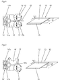
- Fig. 2 shows an alternative preparation of the mixture web 10 by means of a roller die aggregate with a duplex extruder 14 'and a roller Die 15' from a spray head 16 'with a roller 17'. From the unit itself, two extruders 14'a and 14'b are indicated in addition to the spray head 16 '.
- the heatable roller 17 ' forms, together with the head 16', the outlet gap 16'a and can be set into rotary motion by means of a separate drive.
- the roller 17 'therefore limits the exit slit 16'a from below and is adjustable relative to the head 16'.
- the exit slit 16'a has a width and height which are adapted to the width B and thickness of the mixture web 10 to be produced.
- the mixing path 10 can be produced with high accuracy.
- the standard mixture for the middle mixing strip 12 and in the second extruder 14'b the high-performance mixture for the mixing strips 13 plasticized and head 16 'corresponding to the exit slit 16'a transported.
- the according to Fig. 1 or Fig. 2 prepared mixing sheet 10 can be wound into a roll and stored intermediately.
- Fig. 3 shows a possibility according to the invention of the production of a material web 24 of mixing web sections 40'a of two mixing webs 10, as for example and preferably by means of one of the in the Figures 1 or 2 shown aggregates were produced.
- Fig. 3 illustrates a possibility of the basic procedure of the method, the individual components transporting and movable in movement facilities are not shown.
- two mixing path sections 40'a are joined by the rollers 23 with the interposition of a reinforcement carrier web 11.
- the feed direction of the reinforcing material web 11 here corresponds to the removal direction of the formed material web 24.
- the reinforcing material web 11 consists in the embodiment shown of a number of mutually parallel steel cords 11a.
- the two material webs 10 are fed parallel to one another and overlapping at right angles to the reinforcing support web 11 or to the steel cords 11a.
- a portion of the one, here supplied right mixing path 10 is stored on the table, not shown, or on this, a portion of the reinforcing support web 11 and then a portion of the second mixture path 10 is positioned.
- the mixture strips 12 of the standard mixtures and the mixture strips 13 of the high-performance mixtures are placed as exactly as possible on each other. Now, the formed overlapping section of the two mixing paths 10 is cut off laterally of the reinforcement carrier web 11.
- the strength carrier web 11 is transported so much further that the strength carrier web 11 is again provided on both sides with mixing web sections 40'a directly to the mixing web sections 40'a. This results in a web of mixture web sections 40'a with the strength carrier web 11 located between them, which is pressed together, for example, between rolls or rolls 18 of a multi-roll calender to the material web 24 and simultaneously transported on.
- the formed material web 24 is rolled up in a known manner on a roll 25.
- a composite material web 40 is created from the material web 24.
- the material web 24 unrolled from the roll 25 is transported on conveying means 26 and cut centrally by means of a cutting device 27 through the mixing strips 13 into composite material pieces 40a which are lifted on a further conveying device 28 positioned at right angles to the conveying devices 26 and here blunted by material composite web 40 Splices are joined together so that the composite material web 40 in the longitudinal direction has a central portion 40 b, in which the steel cords 11 a, which are not shown embedded in the standard mixture and two edge portions 40c in which the steel cords 11a are embedded in the high-performance compound.
- the embedded steel cords 11a which are not shown, now run transversely to the longitudinal direction of the composite material web 40.
- the composite material web 40 is rolled up onto a roll 29 and can now be laid on the inner layer panel applied to a tire building drum in the tire structure and thus form a carcass ply of a tire.
- the required dimensions of the carcass ply are already taken into account in the production of the mixture web 10.
- composite material webs can be produced which form belt plies.
- the blended webs 10 become Fig. 3 fed at a corresponding angle to each other, so that the cut mixture track sections 40'a form parallelograms with acute and obtuse angles.
- the steel cords 11a then finally run in the finished material composite web at the corresponding angle to the parallel lateral edge portions 40c.
- a mixing path 19 for example for a composite material as a belt layer, is produced from transverse strips of two rubber mixtures.
- Base materials for a belt ply are, for example, a rubber blend web 21 of a high performance blend and a rubber blend web 22 of a standard blend.
- the rubber mixture webs 21, 22 can in a conventional manner, for example by calendering or by means of a roller-head unit or a roller die aggregate getting produced.
- For further processing of the two Rubber mixture webs 21, 22 are used conventional equipment, such as tables and conveyors.
- the rubber mixture web 22 is cut into blend strips 22a whose length corresponds to the aforementioned width b 12 of the blend strips 12.
- the second rubber mixture web 21 from the high-performance mixture is cut by means of a cutting device into narrow mixing strips 21a, the width of which corresponds to twice the width b 13 of the described mixing strips 13.
- a conveyor for example a conveyor belt, to which a mixing piece 22a and a mixing strip 21a are alternately connected to each other by blunt splicing and transported further.
- Two mixture paths 19 can be connected together with a craft carrier web to form a material composite web, for example according to FIG Fig. 3 of the EP 2 327 536 A1 using a four-roll calender.
- the further processing of the resulting composite material web - cutting and reassembling - can according to Fig. 4 and Fig. 5 of the EP 2 327 536 A1 respectively.
- analogous to Fig. 3 and 3a the subject patent application two webs 19 connected in sections with a strength carrier web, cut and further processed accordingly. All material webs are supplied to each other in parallel, the strength carrier alternatively at an acute angle to the webs of material 19th
- the invention is not limited to the illustrated and described embodiments.
- the method according to the invention can also be used to create mixing webs of mixing strips with three or more different rubber mixtures.
- Roller head units or roller die units with multiple extruders are used for this purpose, for example.
Claims (8)
- Procédé de fabrication d'une bande de mélange (19), en particulier pour la fabrication d'un composite de matière contenant des éléments de résistance pour une couche de ceinture (5a, 5b) ou une couche de carcasse (4) d'un pneu radial, dans lequel la bande de mélange (19) se compose de plusieurs rubans de mélange (21a, 22a) s'étendant sous un angle droit ou aigu par rapport à sa direction longitudinale, dans lequel au moins un des rubans de mélange (21a) se compose d'un premier mélange de caoutchouc et au moins un autre ruban de mélange (22a) se compose d'un deuxième mélange de caoutchouc, dans lequel le premier mélange de caoutchouc et le deuxième mélange de caoutchouc présentent des compositions différentes, caractérisé en ce que l'on fabrique une première bande de mélange de caoutchouc (21) avec le premier mélange de caoutchouc et une deuxième bande de mélange de caoutchouc (22) de même largeur que la première bande de mélange de caoutchouc (21) avec le deuxième mélange de caoutchouc, on découpe chaque bande de mélange de caoutchouc (21, 22) transversalement ou sous un angle aigu de même valeur pour les deux bandes de mélange de caoutchouc (21, 22) par rapport à leur extension longitudinale en rubans de mélange de même largeur (21a, 22a), dans lequel les rubans de mélange (21a) de la première bande de mélange de caoutchouc (21) présentent une largeur s'écartant de la largeur des rubans de mélange (22a) de la deuxième bande de mélange de caoutchouc (22), dans lequel on assemble ensuite en alternance, par épissage bout à bout, un ruban de mélange (21a) de la première bande de mélange de caoutchouc (21) avec un ruban de mélange (22a) de la deuxième bande de mélange de caoutchouc (22) et on réunit ainsi les rubans de mélange (21a, 22a) l'un à l'autre en une bande de mélange (19).
- Procédé selon la revendication 1, caractérisé en ce que l'on envoie ladite première bande de mélange de caoutchouc (21) au premier côté et ladite deuxième bande de mélange de caoutchouc (22) au deuxième côté d'un dispositif de transport central et on les découpe en des rubans de mélange (21a, 22a), qui sont ensuite positionnés sur le dispositif de transport central et épissés les uns aux autres.
- Procédé de fabrication d'une bande de matière (24) pour la construction d'une bande composite de matière (40) pour une couche de ceinture (5a, 5b) ou une couche de carcasse (4) d'un pneu radial, à partir de deux bandes de mélange identiques (10) et d'une bande d'éléments de résistance (11) se trouvant entre celles-ci, dans lequel les deux bandes de mélange (10) se composent de plusieurs rubans de mélange (12, 13), dans lequel au moins un des rubans de mélange (12) se compose d'un premier mélange de caoutchouc et au moins un autre ruban de mélange (13) se compose d'un deuxième mélange de caoutchouc, dans lequel le premier mélange de caoutchouc et le deuxième mélange de caoutchouc présentent des compositions différentes, caractérisé en ce que l'on insère la bande d'éléments de résistance (11) par parties entre des parties des deux bandes de mélange (10), qui sont fournies avec recouvrement, sous un angle droit ou sous un angle aigu par rapport à l'extension longitudinale de la bande d'éléments de résistance (11), la première au-dessus, l'autre en dessous de la bande d'éléments de résistance (11), de telle manière que les rubans de mélange (12, 13) composés des mêmes mélanges des deux bandes de mélange (10) soient placés l'un sur l'autre, dans lequel on découpe ensuite la partie à recouvrement formée des deux bandes de mélange (10) latéralement à la bande d'éléments de résistance (11) comme partie de bande de mélange (40'a), dans lequel on transporte ensuite la bande d'éléments de résistance (11) à une distance telle que la partie de mélange suivante (40'a) soit formée directement sur la partie de bande de mélange formée (40'a), dans lequel on comprime la bande ainsi créée composée de la bande d'éléments de résistance (11) garnie avec les parties de bande de mélange (40'a) et on l'évacue simultanément.
- Procédé selon la revendication 3, caractérisé en ce que la bande d'éléments de résistance (11) garnie avec les parties de bande de mélange (40'a) est calandrée en une bande de matière (24) sur une calandre ou analogue.
- Procédé selon la revendication 3 ou 4, caractérisé en ce que l'on coupe la bande de matière (24) parallèlement aux rubans de matière (12, 13) en pièces composites de matière (40a), de telle manière que les pièces composites de matière (40a) puissent être réunies par épissage en une bande composite de matière (40), dans laquelle les rubans de matière (12, 13) sont orientés en direction longitudinale, dans lequel des rubans de matière (12, 13) du même mélange s'étendent de façon continue.
- Procédé selon la revendication 3, caractérisé en ce que l'on fabrique la bande de mélange (10) au moyen d'un groupe Roller-Head ou d'un groupe Roller-Die avec plusieurs extrudeuses (14a, 14b, 14'a, 14'b), correspondant à un nombre de rubans de mélange (12, 13) en mélanges de caoutchouc différents.
- Procédé selon la revendication 6, caractérisé en ce que le groupe Roller-Head présente une tête de projection large (16) avec une buse de projection en forme de fente (16a), dont les dimensions sont adaptées à l'épaisseur et à la largeur (B) de la bande de mélange à fabriquer (10).
- Procédé selon la revendication 3, caractérisé en ce que le groupe Roller-Die présente une tête de projection (16') avec une fente de sortie (16'a) en forme de fente formée entre le rouleau (17') et la tête de projection (16'), dont les dimensions peuvent être adaptées à l'épaisseur et à la largeur (B) de la bande de mélange à fabriquer (10).
Applications Claiming Priority (1)
| Application Number | Priority Date | Filing Date | Title |
|---|---|---|---|
| DE102012104691A DE102012104691A1 (de) | 2012-05-31 | 2012-05-31 | Verfahren zur Herstellung einer Mischungsbahn und Verfahren zur Herstellung einer Materialbahn aus zwei Mischungsbahnen |
Publications (3)
| Publication Number | Publication Date |
|---|---|
| EP2669068A2 EP2669068A2 (fr) | 2013-12-04 |
| EP2669068A3 EP2669068A3 (fr) | 2014-02-26 |
| EP2669068B1 true EP2669068B1 (fr) | 2016-08-31 |
Family
ID=48430494
Family Applications (1)
| Application Number | Title | Priority Date | Filing Date |
|---|---|---|---|
| EP13167424.4A Not-in-force EP2669068B1 (fr) | 2012-05-31 | 2013-05-13 | Procédé de fabrication d'une bande de mélange |
Country Status (2)
| Country | Link |
|---|---|
| EP (1) | EP2669068B1 (fr) |
| DE (1) | DE102012104691A1 (fr) |
Families Citing this family (2)
| Publication number | Priority date | Publication date | Assignee | Title |
|---|---|---|---|---|
| CN104002454B (zh) * | 2014-05-26 | 2016-03-30 | 安徽中意胶带有限责任公司 | 一种双面四层贴面整芯阻燃输送带面胶专用挤出机 |
| DE102014211561A1 (de) * | 2014-06-17 | 2015-12-17 | Continental Reifen Deutschland Gmbh | Verfahren zum Herstellen einer Karkasseinlage |
Family Cites Families (10)
| Publication number | Priority date | Publication date | Assignee | Title |
|---|---|---|---|---|
| GB777734A (en) * | 1954-09-30 | 1957-06-26 | Dunlop Rubber Co | Process and apparatus for making fabrics composed of adhesively-united threads, cords or the like |
| GB1604619A (en) * | 1977-06-18 | 1981-12-09 | Britton A | Fabrics |
| US5173138A (en) * | 1990-08-08 | 1992-12-22 | Blauch Denise A | Method and apparatus for the continuous production of cross-plied material |
| DE69615294T2 (de) * | 1995-07-13 | 2002-04-18 | Sumitomo Rubber Ind | Extrusionsvorrichtung für Elastomer |
| JP2000351145A (ja) * | 1999-06-11 | 2000-12-19 | Sumitomo Rubber Ind Ltd | ローラヘッドゴム押出し装置 |
| EP1448355B1 (fr) * | 2001-05-16 | 2008-11-19 | Société de Technologie Michelin | Appareillage de coextrusion de melanges caoutchouteux |
| JP4426937B2 (ja) * | 2004-09-14 | 2010-03-03 | 住友ゴム工業株式会社 | ゴムストリップの製造装置 |
| DE112005003636B4 (de) * | 2005-07-15 | 2017-08-10 | Toyo Tire & Rubber Co., Ltd. | Verfahren zum Herstellen einer Karkassenlage |
| PL2121294T3 (pl) * | 2006-12-22 | 2011-07-29 | Pirelli | Sposób wytwarzania opon poprzez nanoszenie pasków różnej szerokości |
| DE102009044644A1 (de) | 2009-11-25 | 2011-05-26 | Continental Reifen Deutschland Gmbh | Verfahren zur Herstellung eines Materialverbundes für eine Gürtellage oder für eine Karkasslage eines Radialluftreifens |
-
2012
- 2012-05-31 DE DE102012104691A patent/DE102012104691A1/de not_active Withdrawn
-
2013
- 2013-05-13 EP EP13167424.4A patent/EP2669068B1/fr not_active Not-in-force
Also Published As
| Publication number | Publication date |
|---|---|
| EP2669068A2 (fr) | 2013-12-04 |
| EP2669068A3 (fr) | 2014-02-26 |
| DE102012104691A1 (de) | 2013-12-05 |
Similar Documents
| Publication | Publication Date | Title |
|---|---|---|
| DE60003594T2 (de) | Gummiband mit einem spezifischen Querschnitt zur Verwendung bei der Reifenherstellung | |
| DE60014010T2 (de) | Verfahren und Anlage zum Reifenaufbau | |
| DD263261A5 (de) | Verfahren zur herstellung einer ersten fahrzeugradialreifenvorstufe | |
| EP3157741B1 (fr) | Procédé de production d'une nappe de carcasse | |
| DE19718701C1 (de) | Verfahren zum Herstellen eines Fahrzeugluftreifens | |
| EP2669068B1 (fr) | Procédé de fabrication d'une bande de mélange | |
| DE102005039274A1 (de) | Fahrzeugluftreifen | |
| EP2829419B1 (fr) | Pneus de véhicule | |
| WO2008025598A1 (fr) | Procédé de fabrication d'un bandage cru ou d'une carcasse de bandage cru sur un tambour de confection de bandages | |
| DE1277558B (de) | Verfahren und Mischvorrichtung zum kontinuierlichen Aufbringen der fuer den Aufbau eines Luftreifens erforderlichen Kautschukmischungen auf eine Karkasse | |
| EP1954481B1 (fr) | Procede de fabrication d'un ensemble de ceinture pour bandages pneumatiques de vehicule | |
| EP2327536B1 (fr) | Procédé de fabrication d'un matériau composite pour bandage de pneus ou pour une nappe carcasse d'un pneu radial | |
| EP1816011B1 (fr) | Couche de renforcement pour des pneus Ultra High Performance dans une construction radiale, en particulier pour la fabrication de carcasses de pneus, tout comme procédé de montage de la couche de renforcement sur un tambour de montage de pneus | |
| DE60117944T2 (de) | Verfahren zur Herstellung einer ringförmigen Gummikomponente für einen Luftreifen, sowie Luftreifen enthaltend eine dergestalte Komponente | |
| DE19617598C2 (de) | Herstellung einer Lauffläche mit aufgelegtem Schulterabdeckstreifen | |
| DE102014224422A1 (de) | Verfahren zur Herstellung eines Rohreifens in Radialbauart | |
| EP2808177A1 (fr) | Pneu de roulage à plat | |
| EP1675717B1 (fr) | Procede pour produire un bandage de ceinture d'un pneu de vehicule | |
| DE10327679A1 (de) | Kalanderanlage | |
| EP1759830B1 (fr) | Procédé de fabrication d'un profilé de renforcement d'un pneumatique pour roulage à plat | |
| DE102008003654B4 (de) | Fahrzeugreifen | |
| DE102014209713A1 (de) | Verfahren zur Herstellung von Karkassmaterial oder Gürtelmaterial für Fahrzeugreifen | |
| DE102016214627A1 (de) | Verfahren und Vorrichtung zum Aufbauen eines Fahrzeugluftreifens | |
| DE102014221486A1 (de) | Verfahren zur Herstellung von Vormaterial für Fahrzeugreifen | |
| WO2022111774A1 (fr) | Procédé de production d'un pneumatique pour véhicule |
Legal Events
| Date | Code | Title | Description |
|---|---|---|---|
| PUAI | Public reference made under article 153(3) epc to a published international application that has entered the european phase |
Free format text: ORIGINAL CODE: 0009012 |
|
| AK | Designated contracting states |
Kind code of ref document: A2 Designated state(s): AL AT BE BG CH CY CZ DE DK EE ES FI FR GB GR HR HU IE IS IT LI LT LU LV MC MK MT NL NO PL PT RO RS SE SI SK SM TR |
|
| AX | Request for extension of the european patent |
Extension state: BA ME |
|
| PUAL | Search report despatched |
Free format text: ORIGINAL CODE: 0009013 |
|
| AK | Designated contracting states |
Kind code of ref document: A3 Designated state(s): AL AT BE BG CH CY CZ DE DK EE ES FI FR GB GR HR HU IE IS IT LI LT LU LV MC MK MT NL NO PL PT RO RS SE SI SK SM TR |
|
| AX | Request for extension of the european patent |
Extension state: BA ME |
|
| RIC1 | Information provided on ipc code assigned before grant |
Ipc: B29C 47/32 20060101ALI20140121BHEP Ipc: B29C 47/56 20060101ALI20140121BHEP Ipc: B29C 47/06 20060101ALI20140121BHEP Ipc: B29D 30/42 20060101ALI20140121BHEP Ipc: B29C 47/00 20060101AFI20140121BHEP |
|
| 17P | Request for examination filed |
Effective date: 20140826 |
|
| RBV | Designated contracting states (corrected) |
Designated state(s): AL AT BE BG CH CY CZ DE DK EE ES FI FR GB GR HR HU IE IS IT LI LT LU LV MC MK MT NL NO PL PT RO RS SE SI SK SM TR |
|
| 17Q | First examination report despatched |
Effective date: 20151103 |
|
| REG | Reference to a national code |
Ref country code: DE Ref legal event code: R079 Ref document number: 502013004246 Country of ref document: DE Free format text: PREVIOUS MAIN CLASS: B29C0047000000 Ipc: B29D0030420000 |
|
| GRAP | Despatch of communication of intention to grant a patent |
Free format text: ORIGINAL CODE: EPIDOSNIGR1 |
|
| RIC1 | Information provided on ipc code assigned before grant |
Ipc: B29C 47/00 20060101ALI20160511BHEP Ipc: B29D 30/42 20060101AFI20160511BHEP Ipc: B29L 30/00 20060101ALI20160511BHEP Ipc: B29C 47/32 20060101ALI20160511BHEP Ipc: B29C 65/00 20060101ALI20160511BHEP |
|
| INTG | Intention to grant announced |
Effective date: 20160524 |
|
| GRAS | Grant fee paid |
Free format text: ORIGINAL CODE: EPIDOSNIGR3 |
|
| GRAA | (expected) grant |
Free format text: ORIGINAL CODE: 0009210 |
|
| AK | Designated contracting states |
Kind code of ref document: B1 Designated state(s): AL AT BE BG CH CY CZ DE DK EE ES FI FR GB GR HR HU IE IS IT LI LT LU LV MC MK MT NL NO PL PT RO RS SE SI SK SM TR |
|
| REG | Reference to a national code |
Ref country code: CH Ref legal event code: EP Ref country code: GB Ref legal event code: FG4D Free format text: NOT ENGLISH |
|
| REG | Reference to a national code |
Ref country code: IE Ref legal event code: FG4D Free format text: LANGUAGE OF EP DOCUMENT: GERMAN |
|
| REG | Reference to a national code |
Ref country code: DE Ref legal event code: R096 Ref document number: 502013004246 Country of ref document: DE |
|
| REG | Reference to a national code |
Ref country code: AT Ref legal event code: REF Ref document number: 824628 Country of ref document: AT Kind code of ref document: T Effective date: 20161015 |
|
| REG | Reference to a national code |
Ref country code: LT Ref legal event code: MG4D |
|
| REG | Reference to a national code |
Ref country code: NL Ref legal event code: MP Effective date: 20160831 |
|
| PG25 | Lapsed in a contracting state [announced via postgrant information from national office to epo] |
Ref country code: HR Free format text: LAPSE BECAUSE OF FAILURE TO SUBMIT A TRANSLATION OF THE DESCRIPTION OR TO PAY THE FEE WITHIN THE PRESCRIBED TIME-LIMIT Effective date: 20160831 Ref country code: FI Free format text: LAPSE BECAUSE OF FAILURE TO SUBMIT A TRANSLATION OF THE DESCRIPTION OR TO PAY THE FEE WITHIN THE PRESCRIBED TIME-LIMIT Effective date: 20160831 Ref country code: LT Free format text: LAPSE BECAUSE OF FAILURE TO SUBMIT A TRANSLATION OF THE DESCRIPTION OR TO PAY THE FEE WITHIN THE PRESCRIBED TIME-LIMIT Effective date: 20160831 Ref country code: RS Free format text: LAPSE BECAUSE OF FAILURE TO SUBMIT A TRANSLATION OF THE DESCRIPTION OR TO PAY THE FEE WITHIN THE PRESCRIBED TIME-LIMIT Effective date: 20160831 Ref country code: NO Free format text: LAPSE BECAUSE OF FAILURE TO SUBMIT A TRANSLATION OF THE DESCRIPTION OR TO PAY THE FEE WITHIN THE PRESCRIBED TIME-LIMIT Effective date: 20161130 |
|
| PG25 | Lapsed in a contracting state [announced via postgrant information from national office to epo] |
Ref country code: SE Free format text: LAPSE BECAUSE OF FAILURE TO SUBMIT A TRANSLATION OF THE DESCRIPTION OR TO PAY THE FEE WITHIN THE PRESCRIBED TIME-LIMIT Effective date: 20160831 Ref country code: ES Free format text: LAPSE BECAUSE OF FAILURE TO SUBMIT A TRANSLATION OF THE DESCRIPTION OR TO PAY THE FEE WITHIN THE PRESCRIBED TIME-LIMIT Effective date: 20160831 Ref country code: NL Free format text: LAPSE BECAUSE OF FAILURE TO SUBMIT A TRANSLATION OF THE DESCRIPTION OR TO PAY THE FEE WITHIN THE PRESCRIBED TIME-LIMIT Effective date: 20160831 Ref country code: LV Free format text: LAPSE BECAUSE OF FAILURE TO SUBMIT A TRANSLATION OF THE DESCRIPTION OR TO PAY THE FEE WITHIN THE PRESCRIBED TIME-LIMIT Effective date: 20160831 Ref country code: GR Free format text: LAPSE BECAUSE OF FAILURE TO SUBMIT A TRANSLATION OF THE DESCRIPTION OR TO PAY THE FEE WITHIN THE PRESCRIBED TIME-LIMIT Effective date: 20161201 |
|
| PG25 | Lapsed in a contracting state [announced via postgrant information from national office to epo] |
Ref country code: EE Free format text: LAPSE BECAUSE OF FAILURE TO SUBMIT A TRANSLATION OF THE DESCRIPTION OR TO PAY THE FEE WITHIN THE PRESCRIBED TIME-LIMIT Effective date: 20160831 Ref country code: RO Free format text: LAPSE BECAUSE OF FAILURE TO SUBMIT A TRANSLATION OF THE DESCRIPTION OR TO PAY THE FEE WITHIN THE PRESCRIBED TIME-LIMIT Effective date: 20160831 |
|
| PG25 | Lapsed in a contracting state [announced via postgrant information from national office to epo] |
Ref country code: PT Free format text: LAPSE BECAUSE OF FAILURE TO SUBMIT A TRANSLATION OF THE DESCRIPTION OR TO PAY THE FEE WITHIN THE PRESCRIBED TIME-LIMIT Effective date: 20170102 Ref country code: DK Free format text: LAPSE BECAUSE OF FAILURE TO SUBMIT A TRANSLATION OF THE DESCRIPTION OR TO PAY THE FEE WITHIN THE PRESCRIBED TIME-LIMIT Effective date: 20160831 Ref country code: BG Free format text: LAPSE BECAUSE OF FAILURE TO SUBMIT A TRANSLATION OF THE DESCRIPTION OR TO PAY THE FEE WITHIN THE PRESCRIBED TIME-LIMIT Effective date: 20161130 Ref country code: CZ Free format text: LAPSE BECAUSE OF FAILURE TO SUBMIT A TRANSLATION OF THE DESCRIPTION OR TO PAY THE FEE WITHIN THE PRESCRIBED TIME-LIMIT Effective date: 20160831 Ref country code: SM Free format text: LAPSE BECAUSE OF FAILURE TO SUBMIT A TRANSLATION OF THE DESCRIPTION OR TO PAY THE FEE WITHIN THE PRESCRIBED TIME-LIMIT Effective date: 20160831 Ref country code: SK Free format text: LAPSE BECAUSE OF FAILURE TO SUBMIT A TRANSLATION OF THE DESCRIPTION OR TO PAY THE FEE WITHIN THE PRESCRIBED TIME-LIMIT Effective date: 20160831 Ref country code: PL Free format text: LAPSE BECAUSE OF FAILURE TO SUBMIT A TRANSLATION OF THE DESCRIPTION OR TO PAY THE FEE WITHIN THE PRESCRIBED TIME-LIMIT Effective date: 20160831 |
|
| REG | Reference to a national code |
Ref country code: DE Ref legal event code: R097 Ref document number: 502013004246 Country of ref document: DE |
|
| PG25 | Lapsed in a contracting state [announced via postgrant information from national office to epo] |
Ref country code: IT Free format text: LAPSE BECAUSE OF FAILURE TO SUBMIT A TRANSLATION OF THE DESCRIPTION OR TO PAY THE FEE WITHIN THE PRESCRIBED TIME-LIMIT Effective date: 20160831 |
|
| PLBE | No opposition filed within time limit |
Free format text: ORIGINAL CODE: 0009261 |
|
| STAA | Information on the status of an ep patent application or granted ep patent |
Free format text: STATUS: NO OPPOSITION FILED WITHIN TIME LIMIT |
|
| 26N | No opposition filed |
Effective date: 20170601 |
|
| PG25 | Lapsed in a contracting state [announced via postgrant information from national office to epo] |
Ref country code: LU Free format text: LAPSE BECAUSE OF NON-PAYMENT OF DUE FEES Effective date: 20170531 Ref country code: SI Free format text: LAPSE BECAUSE OF FAILURE TO SUBMIT A TRANSLATION OF THE DESCRIPTION OR TO PAY THE FEE WITHIN THE PRESCRIBED TIME-LIMIT Effective date: 20160831 |
|
| REG | Reference to a national code |
Ref country code: CH Ref legal event code: PL |
|
| GBPC | Gb: european patent ceased through non-payment of renewal fee |
Effective date: 20170513 |
|
| PG25 | Lapsed in a contracting state [announced via postgrant information from national office to epo] |
Ref country code: MC Free format text: LAPSE BECAUSE OF FAILURE TO SUBMIT A TRANSLATION OF THE DESCRIPTION OR TO PAY THE FEE WITHIN THE PRESCRIBED TIME-LIMIT Effective date: 20160831 |
|
| REG | Reference to a national code |
Ref country code: IE Ref legal event code: MM4A |
|
| PG25 | Lapsed in a contracting state [announced via postgrant information from national office to epo] |
Ref country code: LI Free format text: LAPSE BECAUSE OF NON-PAYMENT OF DUE FEES Effective date: 20170531 Ref country code: CH Free format text: LAPSE BECAUSE OF NON-PAYMENT OF DUE FEES Effective date: 20170531 |
|
| REG | Reference to a national code |
Ref country code: FR Ref legal event code: ST Effective date: 20180131 |
|
| PG25 | Lapsed in a contracting state [announced via postgrant information from national office to epo] |
Ref country code: LU Free format text: LAPSE BECAUSE OF NON-PAYMENT OF DUE FEES Effective date: 20170513 |
|
| REG | Reference to a national code |
Ref country code: BE Ref legal event code: MM Effective date: 20170531 |
|
| PG25 | Lapsed in a contracting state [announced via postgrant information from national office to epo] |
Ref country code: GB Free format text: LAPSE BECAUSE OF NON-PAYMENT OF DUE FEES Effective date: 20170513 Ref country code: IE Free format text: LAPSE BECAUSE OF NON-PAYMENT OF DUE FEES Effective date: 20170513 |
|
| PG25 | Lapsed in a contracting state [announced via postgrant information from national office to epo] |
Ref country code: FR Free format text: LAPSE BECAUSE OF NON-PAYMENT OF DUE FEES Effective date: 20170531 |
|
| PGFP | Annual fee paid to national office [announced via postgrant information from national office to epo] |
Ref country code: DE Payment date: 20180531 Year of fee payment: 6 |
|
| PG25 | Lapsed in a contracting state [announced via postgrant information from national office to epo] |
Ref country code: BE Free format text: LAPSE BECAUSE OF NON-PAYMENT OF DUE FEES Effective date: 20170531 |
|
| PG25 | Lapsed in a contracting state [announced via postgrant information from national office to epo] |
Ref country code: MT Free format text: LAPSE BECAUSE OF FAILURE TO SUBMIT A TRANSLATION OF THE DESCRIPTION OR TO PAY THE FEE WITHIN THE PRESCRIBED TIME-LIMIT Effective date: 20160831 |
|
| PG25 | Lapsed in a contracting state [announced via postgrant information from national office to epo] |
Ref country code: AL Free format text: LAPSE BECAUSE OF FAILURE TO SUBMIT A TRANSLATION OF THE DESCRIPTION OR TO PAY THE FEE WITHIN THE PRESCRIBED TIME-LIMIT Effective date: 20160831 |
|
| PG25 | Lapsed in a contracting state [announced via postgrant information from national office to epo] |
Ref country code: HU Free format text: LAPSE BECAUSE OF FAILURE TO SUBMIT A TRANSLATION OF THE DESCRIPTION OR TO PAY THE FEE WITHIN THE PRESCRIBED TIME-LIMIT; INVALID AB INITIO Effective date: 20130513 |
|
| REG | Reference to a national code |
Ref country code: AT Ref legal event code: MM01 Ref document number: 824628 Country of ref document: AT Kind code of ref document: T Effective date: 20180513 |
|
| PG25 | Lapsed in a contracting state [announced via postgrant information from national office to epo] |
Ref country code: CY Free format text: LAPSE BECAUSE OF NON-PAYMENT OF DUE FEES Effective date: 20160831 Ref country code: AT Free format text: LAPSE BECAUSE OF NON-PAYMENT OF DUE FEES Effective date: 20180513 |
|
| PG25 | Lapsed in a contracting state [announced via postgrant information from national office to epo] |
Ref country code: MK Free format text: LAPSE BECAUSE OF FAILURE TO SUBMIT A TRANSLATION OF THE DESCRIPTION OR TO PAY THE FEE WITHIN THE PRESCRIBED TIME-LIMIT Effective date: 20160831 |
|
| REG | Reference to a national code |
Ref country code: DE Ref legal event code: R119 Ref document number: 502013004246 Country of ref document: DE |
|
| PG25 | Lapsed in a contracting state [announced via postgrant information from national office to epo] |
Ref country code: TR Free format text: LAPSE BECAUSE OF FAILURE TO SUBMIT A TRANSLATION OF THE DESCRIPTION OR TO PAY THE FEE WITHIN THE PRESCRIBED TIME-LIMIT Effective date: 20160831 |
|
| PG25 | Lapsed in a contracting state [announced via postgrant information from national office to epo] |
Ref country code: DE Free format text: LAPSE BECAUSE OF NON-PAYMENT OF DUE FEES Effective date: 20191203 |
|
| PG25 | Lapsed in a contracting state [announced via postgrant information from national office to epo] |
Ref country code: IS Free format text: LAPSE BECAUSE OF FAILURE TO SUBMIT A TRANSLATION OF THE DESCRIPTION OR TO PAY THE FEE WITHIN THE PRESCRIBED TIME-LIMIT Effective date: 20161231 |