EP2669068B1 - Method for producing a mixed sheet - Google Patents
Method for producing a mixed sheet Download PDFInfo
- Publication number
- EP2669068B1 EP2669068B1 EP13167424.4A EP13167424A EP2669068B1 EP 2669068 B1 EP2669068 B1 EP 2669068B1 EP 13167424 A EP13167424 A EP 13167424A EP 2669068 B1 EP2669068 B1 EP 2669068B1
- Authority
- EP
- European Patent Office
- Prior art keywords
- mixture
- web
- rubber
- strips
- webs
- Prior art date
- Legal status (The legal status is an assumption and is not a legal conclusion. Google has not performed a legal analysis and makes no representation as to the accuracy of the status listed.)
- Not-in-force
Links
Images


Classifications
-
- B—PERFORMING OPERATIONS; TRANSPORTING
- B29—WORKING OF PLASTICS; WORKING OF SUBSTANCES IN A PLASTIC STATE IN GENERAL
- B29D—PRODUCING PARTICULAR ARTICLES FROM PLASTICS OR FROM SUBSTANCES IN A PLASTIC STATE
- B29D30/00—Producing pneumatic or solid tyres or parts thereof
- B29D30/06—Pneumatic tyres or parts thereof (e.g. produced by casting, moulding, compression moulding, injection moulding, centrifugal casting)
- B29D30/38—Textile inserts, e.g. cord or canvas layers, for tyres; Treatment of inserts prior to building the tyre
- B29D30/42—Endless textile bands without bead-rings
-
- B—PERFORMING OPERATIONS; TRANSPORTING
- B29—WORKING OF PLASTICS; WORKING OF SUBSTANCES IN A PLASTIC STATE IN GENERAL
- B29B—PREPARATION OR PRETREATMENT OF THE MATERIAL TO BE SHAPED; MAKING GRANULES OR PREFORMS; RECOVERY OF PLASTICS OR OTHER CONSTITUENTS OF WASTE MATERIAL CONTAINING PLASTICS
- B29B7/00—Mixing; Kneading
- B29B7/74—Mixing; Kneading using other mixers or combinations of mixers, e.g. of dissimilar mixers ; Plant
- B29B7/7476—Systems, i.e. flow charts or diagrams; Plants
- B29B7/7495—Systems, i.e. flow charts or diagrams; Plants for mixing rubber
-
- B—PERFORMING OPERATIONS; TRANSPORTING
- B29—WORKING OF PLASTICS; WORKING OF SUBSTANCES IN A PLASTIC STATE IN GENERAL
- B29C—SHAPING OR JOINING OF PLASTICS; SHAPING OF MATERIAL IN A PLASTIC STATE, NOT OTHERWISE PROVIDED FOR; AFTER-TREATMENT OF THE SHAPED PRODUCTS, e.g. REPAIRING
- B29C48/00—Extrusion moulding, i.e. expressing the moulding material through a die or nozzle which imparts the desired form; Apparatus therefor
- B29C48/001—Combinations of extrusion moulding with other shaping operations
- B29C48/0018—Combinations of extrusion moulding with other shaping operations combined with shaping by orienting, stretching or shrinking, e.g. film blowing
-
- B—PERFORMING OPERATIONS; TRANSPORTING
- B29—WORKING OF PLASTICS; WORKING OF SUBSTANCES IN A PLASTIC STATE IN GENERAL
- B29C—SHAPING OR JOINING OF PLASTICS; SHAPING OF MATERIAL IN A PLASTIC STATE, NOT OTHERWISE PROVIDED FOR; AFTER-TREATMENT OF THE SHAPED PRODUCTS, e.g. REPAIRING
- B29C48/00—Extrusion moulding, i.e. expressing the moulding material through a die or nozzle which imparts the desired form; Apparatus therefor
- B29C48/03—Extrusion moulding, i.e. expressing the moulding material through a die or nozzle which imparts the desired form; Apparatus therefor characterised by the shape of the extruded material at extrusion
- B29C48/07—Flat, e.g. panels
-
- B—PERFORMING OPERATIONS; TRANSPORTING
- B29—WORKING OF PLASTICS; WORKING OF SUBSTANCES IN A PLASTIC STATE IN GENERAL
- B29C—SHAPING OR JOINING OF PLASTICS; SHAPING OF MATERIAL IN A PLASTIC STATE, NOT OTHERWISE PROVIDED FOR; AFTER-TREATMENT OF THE SHAPED PRODUCTS, e.g. REPAIRING
- B29C48/00—Extrusion moulding, i.e. expressing the moulding material through a die or nozzle which imparts the desired form; Apparatus therefor
- B29C48/16—Articles comprising two or more components, e.g. co-extruded layers
- B29C48/18—Articles comprising two or more components, e.g. co-extruded layers the components being layers
- B29C48/19—Articles comprising two or more components, e.g. co-extruded layers the components being layers the layers being joined at their edges
-
- B—PERFORMING OPERATIONS; TRANSPORTING
- B29—WORKING OF PLASTICS; WORKING OF SUBSTANCES IN A PLASTIC STATE IN GENERAL
- B29C—SHAPING OR JOINING OF PLASTICS; SHAPING OF MATERIAL IN A PLASTIC STATE, NOT OTHERWISE PROVIDED FOR; AFTER-TREATMENT OF THE SHAPED PRODUCTS, e.g. REPAIRING
- B29C48/00—Extrusion moulding, i.e. expressing the moulding material through a die or nozzle which imparts the desired form; Apparatus therefor
- B29C48/16—Articles comprising two or more components, e.g. co-extruded layers
- B29C48/18—Articles comprising two or more components, e.g. co-extruded layers the components being layers
- B29C48/20—Articles comprising two or more components, e.g. co-extruded layers the components being layers one of the layers being a strip, e.g. a partially embedded strip
-
- B—PERFORMING OPERATIONS; TRANSPORTING
- B29—WORKING OF PLASTICS; WORKING OF SUBSTANCES IN A PLASTIC STATE IN GENERAL
- B29C—SHAPING OR JOINING OF PLASTICS; SHAPING OF MATERIAL IN A PLASTIC STATE, NOT OTHERWISE PROVIDED FOR; AFTER-TREATMENT OF THE SHAPED PRODUCTS, e.g. REPAIRING
- B29C48/00—Extrusion moulding, i.e. expressing the moulding material through a die or nozzle which imparts the desired form; Apparatus therefor
- B29C48/25—Component parts, details or accessories; Auxiliary operations
- B29C48/30—Extrusion nozzles or dies
- B29C48/35—Extrusion nozzles or dies with rollers
-
- B—PERFORMING OPERATIONS; TRANSPORTING
- B29—WORKING OF PLASTICS; WORKING OF SUBSTANCES IN A PLASTIC STATE IN GENERAL
- B29C—SHAPING OR JOINING OF PLASTICS; SHAPING OF MATERIAL IN A PLASTIC STATE, NOT OTHERWISE PROVIDED FOR; AFTER-TREATMENT OF THE SHAPED PRODUCTS, e.g. REPAIRING
- B29C48/00—Extrusion moulding, i.e. expressing the moulding material through a die or nozzle which imparts the desired form; Apparatus therefor
- B29C48/25—Component parts, details or accessories; Auxiliary operations
- B29C48/36—Means for plasticising or homogenising the moulding material or forcing it through the nozzle or die
- B29C48/49—Means for plasticising or homogenising the moulding material or forcing it through the nozzle or die using two or more extruders to feed one die or nozzle
-
- B—PERFORMING OPERATIONS; TRANSPORTING
- B29—WORKING OF PLASTICS; WORKING OF SUBSTANCES IN A PLASTIC STATE IN GENERAL
- B29C—SHAPING OR JOINING OF PLASTICS; SHAPING OF MATERIAL IN A PLASTIC STATE, NOT OTHERWISE PROVIDED FOR; AFTER-TREATMENT OF THE SHAPED PRODUCTS, e.g. REPAIRING
- B29C66/00—General aspects of processes or apparatus for joining preformed parts
- B29C66/01—General aspects dealing with the joint area or with the area to be joined
- B29C66/05—Particular design of joint configurations
- B29C66/10—Particular design of joint configurations particular design of the joint cross-sections
- B29C66/11—Joint cross-sections comprising a single joint-segment, i.e. one of the parts to be joined comprising a single joint-segment in the joint cross-section
- B29C66/114—Single butt joints
- B29C66/1142—Single butt to butt joints
-
- B—PERFORMING OPERATIONS; TRANSPORTING
- B29—WORKING OF PLASTICS; WORKING OF SUBSTANCES IN A PLASTIC STATE IN GENERAL
- B29C—SHAPING OR JOINING OF PLASTICS; SHAPING OF MATERIAL IN A PLASTIC STATE, NOT OTHERWISE PROVIDED FOR; AFTER-TREATMENT OF THE SHAPED PRODUCTS, e.g. REPAIRING
- B29C66/00—General aspects of processes or apparatus for joining preformed parts
- B29C66/40—General aspects of joining substantially flat articles, e.g. plates, sheets or web-like materials; Making flat seams in tubular or hollow articles; Joining single elements to substantially flat surfaces
- B29C66/41—Joining substantially flat articles ; Making flat seams in tubular or hollow articles
- B29C66/43—Joining a relatively small portion of the surface of said articles
- B29C66/435—Making large sheets by joining smaller ones or strips together
-
- B—PERFORMING OPERATIONS; TRANSPORTING
- B29—WORKING OF PLASTICS; WORKING OF SUBSTANCES IN A PLASTIC STATE IN GENERAL
- B29C—SHAPING OR JOINING OF PLASTICS; SHAPING OF MATERIAL IN A PLASTIC STATE, NOT OTHERWISE PROVIDED FOR; AFTER-TREATMENT OF THE SHAPED PRODUCTS, e.g. REPAIRING
- B29C66/00—General aspects of processes or apparatus for joining preformed parts
- B29C66/40—General aspects of joining substantially flat articles, e.g. plates, sheets or web-like materials; Making flat seams in tubular or hollow articles; Joining single elements to substantially flat surfaces
- B29C66/47—Joining single elements to sheets, plates or other substantially flat surfaces
- B29C66/472—Joining single elements to sheets, plates or other substantially flat surfaces said single elements being substantially flat
-
- B—PERFORMING OPERATIONS; TRANSPORTING
- B29—WORKING OF PLASTICS; WORKING OF SUBSTANCES IN A PLASTIC STATE IN GENERAL
- B29C—SHAPING OR JOINING OF PLASTICS; SHAPING OF MATERIAL IN A PLASTIC STATE, NOT OTHERWISE PROVIDED FOR; AFTER-TREATMENT OF THE SHAPED PRODUCTS, e.g. REPAIRING
- B29C66/00—General aspects of processes or apparatus for joining preformed parts
- B29C66/70—General aspects of processes or apparatus for joining preformed parts characterised by the composition, physical properties or the structure of the material of the parts to be joined; Joining with non-plastics material
- B29C66/71—General aspects of processes or apparatus for joining preformed parts characterised by the composition, physical properties or the structure of the material of the parts to be joined; Joining with non-plastics material characterised by the composition of the plastics material of the parts to be joined
- B29C66/712—General aspects of processes or apparatus for joining preformed parts characterised by the composition, physical properties or the structure of the material of the parts to be joined; Joining with non-plastics material characterised by the composition of the plastics material of the parts to be joined the composition of one of the parts to be joined being different from the composition of the other part
-
- B—PERFORMING OPERATIONS; TRANSPORTING
- B29—WORKING OF PLASTICS; WORKING OF SUBSTANCES IN A PLASTIC STATE IN GENERAL
- B29D—PRODUCING PARTICULAR ARTICLES FROM PLASTICS OR FROM SUBSTANCES IN A PLASTIC STATE
- B29D30/00—Producing pneumatic or solid tyres or parts thereof
- B29D30/06—Pneumatic tyres or parts thereof (e.g. produced by casting, moulding, compression moulding, injection moulding, centrifugal casting)
- B29D30/38—Textile inserts, e.g. cord or canvas layers, for tyres; Treatment of inserts prior to building the tyre
- B29D30/42—Endless textile bands without bead-rings
- B29D2030/421—General aspects of the joining methods and devices for creating the bands
- B29D2030/422—Butt joining
-
- B—PERFORMING OPERATIONS; TRANSPORTING
- B29—WORKING OF PLASTICS; WORKING OF SUBSTANCES IN A PLASTIC STATE IN GENERAL
- B29L—INDEXING SCHEME ASSOCIATED WITH SUBCLASS B29C, RELATING TO PARTICULAR ARTICLES
- B29L2030/00—Pneumatic or solid tyres or parts thereof
Definitions
- the invention relates to a method for producing a mixture web, in particular for producing a reinforcing material-containing composite material for a belt layer or a carcass ply of a pneumatic radial tire, wherein the mixture web composed of a plurality of extending in their longitudinal direction of mixing strip, wherein at least one of the mixture strips of a first rubber mixture and at least another mixture strip consists of a second rubber mixture, wherein the first rubber mixture and the second rubber mixture have different compositions.
- the invention relates to a method for producing a material web for creating a composite material web for a belt layer or a carcass ply of a pneumatic radial tire, two equal mixing paths and a reinforcing carrier web located between them, wherein the two mixing paths consist of several mixture strips, wherein at least one of the mixture strips of a first rubber mixture and at least one further mixing strip consists of a second rubber mixture, wherein the first rubber mixture and the second rubber mixture have different compositions,
- Each blend web consists of longitudinally extending blend strips which are extrusion prepared and then rolled rubber blends.
- the mixture web is cut transversely or at an acute angle to its longitudinal extension into equal sized pieces of web.
- the individual pieces of track become dull in this way spliced together that their previous cut edges form the longitudinal edges of the now new mixing path, which is connected to each other by a second coincidentally created mixing path and the strength carrier web by calendering that same rubber mixtures are positioned one on the other.
- the composite material web thus formed is cut into equal pieces, which are connected at their uncut edges to form a web in which the mixture strips extend as in the original mixing paths.
- a method for producing a carcass ply is known from US 2009/145532 known.
- two mixing webs having different widths are cut into blend strips, whereby wider blend strips are produced from the wider blend web than from the narrower blend web.
- the mixture strips are connected at their side surfaces.
- the invention has for its object to be able to produce mixing tracks of mixture strips of different rubber mixtures in a particularly accurate and efficient manner.
- the invention is further based on the object, a composite material consisting of two mixing paths and a reinforcing material web with a lower cost than that according to the EP 2 327 536 A1 to be able to produce.
- a mixture web of a plurality of mixing strips extending at right angles or at an acute angle to their longitudinal direction can be produced in accordance with the invention in accordance with claim 1 such that a first rubber blend web of the first rubber blend and a second rubber blend web of the same width as the first rubber blend web are prepared from the second rubber blend, each rubber blend web is cut across equal width or equal width strips at either equal or acute angle to both blends for both rubber blend webs; the width of the first rubber blend web is different from the width of the blend stripes of the second rubber blend web, and then alternately a blend strip of the first rubber blend web with a blend strip of the second Bonded rubber sheet by blunt splicing and so the blend strips are joined together to form the mixture path.
- This process is particularly efficient when the one rubber mixing web is fed to the one and the second rubber mixture web on the second side of a central conveyor and the mixture strips are cut, which are then positioned and spliced together on the central conveyor.
- the material web of the aforementioned type is produced according to the invention according to claim 3 such that the reinforcing material web is inserted in sections between sections of the two mixing paths, which at right angles or at an acute angle to the longitudinal extent of the reinforcing material web, a mixture above, the other below the reinforcement web, be supplied overlapping , such that the mixture of equal mixtures of the two mixing paths lie on each other, then the formed overlap portion of the two mixing paths is laterally cut off the strength carrier web as a mixing path section, wherein subsequently the strength carrier web is transported so much further that directly to the formed Mixture web section then the next mixture track section is formed, wherein the resulting web from the be with the mixing track sections be The reinforcement web is pressed together and simultaneously transported.
- the strength carrier web coated with the mixture web sections can be calendered on a multi-roll calender or the like to the material web.
- mixing webs or material webs are produced for the production of composite material webs.
- a belt layer or a carcass ply is formed from the produced composite material webs for use in tire construction.
- the mixing paths can be fed either at right angles or at an acute angle to the longitudinal extent of the reinforcement carrier web.
- the strength carriers run in the longitudinal direction of the resulting web, in a supply at right angles across the mixture strips, in the case of an acute angle at a corresponding acute angle to the mixture strips, so that in the latter way composite material webs can be formed, which is used to build belt layers in pneumatic vehicle tires become.
- the mentioned material web forms an intermediate step in the production of the composite material web which can be used in tire construction.
- the material web is cut parallel to the material strips in composite material so that the composite material pieces are joined by splicing to form a composite material web, in which the strips of material are oriented in the longitudinal direction, wherein material strips of the same mixture are continuous.
- the processes according to the invention open up expedient and automated processes in the individual process steps to produce mixing webs and composite material webs from blend strips of different rubber mixture compositions and different dimensions in a simple manner.
- the mixing web can be produced by means of a roller-head aggregate or a roller-die-aggregate with several extruders, corresponding to the number of mixture strips of different rubber mixtures.
- a roller-head unit is understood to mean the combination of an extruder or a plurality of extruders with a full-width spray head and a two-roll calender.
- a roller head unit offers the advantage of a high uniformity of the thickness of the produced material web over the full width of the web and an excellent homogeneity of the rolled material.
- a scooter-head aggregate also allows the production of thin mixture webs of large width and small thickness, as it is important, for example, for mixing webs for belt layers and carcass layers of a pneumatic vehicle tire with a thickness of 0.5 mm to 2 mm.
- the rubber compounds are plasticized in the extruders and fed into the roller head. From this, the mixtures pass over the entire working width of the calender directly into the nip.
- a roller-die-aggregate is understood to mean the combination of an extruder or a plurality of extruders with a spray head with a roller, the roller being part of the head since it forms the mixing path.
- Roller die aggregates also have the advantage that thin rubber compound webs can be produced with high accuracy.
- the rubber compounds are delivered under low pressure in appropriate positions and without additional thermal stress in the forming gap.
- drag effects occur in the head area and in the molding gap which are caused by the mixture adhesion on the tempered roll surface.
- the high accuracy of the mixing paths produced with a roller head unit or a roller die aggregate is based on the fact that in the case of the roller head unit, this has a wide spray head with a slot-shaped spray nozzle whose dimensions are based on thickness and the width of the mixture web to be produced are adapted or adaptable and in the case of using a roller die aggregate that this has a spray head with a slot-shaped outlet gap formed between the roller and the spray head, the dimensions of the thickness and the width of the produced Mixing track are customizable.
- the in Fig. 5 exemplary radial and pneumatic tires for passenger cars has common tire components, in particular a profiled tread 1, side walls 2, bead areas with bead cores 3, an airtight inner layer 6, a carcass ply 4 and a belt assembly with two belt plies 5a, 5b.
- the strength element in the carcass ply 4 are embedded in rubber and components of a fabric.
- the two free end portions of the carcass ply 4 looped from axially inside to axially outside around the bead cores 3 form carcass cuffs 4a.
- the belt layers 5a, 5b extending in the circumferential direction between the carcass ply 4 and the tread 1 consist of rubber cords embedded in rubber and in each layer parallel to one another.
- the steel cords in one belt ply 5a are crossed to the steel cords in the other belt ply 5b, and the angle which the steel cords enclose with the tire circumferential direction is about on the order of ⁇ 15 ° to ⁇ 30 °.
- trucks tires are usually four belt layers, also made of rubber embedded and running parallel to each other in each layer steel cords, provided in the belt association.
- the single- or multi-ply carcass ply in truck tires usually consists of steel cord embedded in rubber, at least substantially extending in the radial direction.
- the belt plies and the carcass plies are in each case uniformly formed components in passenger car and in truck tires.
- Fig. 5 shows by way of example edge portions 5'a, 5'b of the belt plies 5a, 5b, end portions 4'a of the high blows 4a and portions 41 in the so-called basket arch areas of the carcass ply 4, which are made of special gum blends. Analogous versions of these components are also possible with truck tires, as for example in Fig. 2 of the EP 2 327 536 A1 is shown.
- the edge sections 5'a, 5'b of the belt plies 5a, 5b and the end sections 4'a of the carcass bumps 4a are produced in particular from so-called high-performance blends, which are rubber blends which, with regard to relevant properties in these sections, such as, for example, crack resistance, Tear resistance and fatigue resistance, are optimized.
- the sections 41 in the basket arch areas mainly have particularly penetration-resistant rubber compounds.
- High-performance compounds are designed differently for truck and car tires and for belt layers and carcass layers, and also differ from the other penetration-resistant mixtures of the basket arch portions 41.
- the embedding gums outside of the mentioned edge portions 15a, 15b, 4'a and the portions 41 can be made of lower cost rubber compounds, since they need not be optimized with respect to the mentioned properties in these areas. These mixtures are referred to below as standard mixtures.
- the sections 5'a, 5'b, 4'a produced from a high-performance mixture each have a constant width, depending on the type of tire, between 3 mm and 30 mm.
- the portions 41 made of a penetration-resistant mixture in the basket arch areas substantially extend between the edges of the widest belt ply and the site with the largest cross-sectional width of the tire, possibly also only over a part of this area.
- a mixing web 10 with a total width B consisting of a mixture strip 12 of a width b 12 made of a standard mixture and two edge strips 13 of the width b 13 made of a high-performance mixture, is produced for the time being.
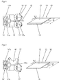
- Fig. 1 and Fig. 2 each show a portion of the prepared mixing path 10. According to the in Fig. 1 embodiment of the invention shown, the preparation of the mixture web 10 by means of a roller-head unit with a duplex extruder 14 with a roller head 15.
- roller head units in the rubber processing industry, in particular for the production of semi-finished products in the manufacture of pneumatic vehicle tires, for example of treads.
- This in Fig. 1 The unit shown has, in addition to other components not shown, two extruders 14a, 14b and a full-width spray head 16 with a slot-shaped spray nozzle 16a, the length of the width B of the mixture to be produced 10 and the height of the thickness of the mixture to be produced 10 are adjusted.
- the extruder 14a a plasticized rubber composition according to the standard low pressure mixture in the head 16 in the central portion of the spray nozzle 16a is discharged from the spray head 16.
- a high-performance mixture is produced, which is split in the spray head 16 and at the lateral portions of the spray nozzle 16a passes under low pressure to the outside.
- the flow paths in the spray head 16 are designed such that the rubber mixture for the mixing strip 12 and laterally the rubber mixture for the mixing strip 13 emerges from the spray nozzle 16a in the middle section.
- Fig. 1 shows the immediately adjacent to the spray nozzle 16a roller head 15, a roll calender of two rollers 17, which are set in rotary motion, the directions of rotation being indicated by arrows.
- the rubber mixtures emerging from the spray nozzle 16a enter directly into the nip 17a and are here calibrated or finely adjusted with regard to their desired thickness. From the nip 17a, the mixture path 10 emerges as described above.
- Fig. 2 shows an alternative preparation of the mixture web 10 by means of a roller die aggregate with a duplex extruder 14 'and a roller Die 15' from a spray head 16 'with a roller 17'. From the unit itself, two extruders 14'a and 14'b are indicated in addition to the spray head 16 '.
- the heatable roller 17 ' forms, together with the head 16', the outlet gap 16'a and can be set into rotary motion by means of a separate drive.
- the roller 17 'therefore limits the exit slit 16'a from below and is adjustable relative to the head 16'.
- the exit slit 16'a has a width and height which are adapted to the width B and thickness of the mixture web 10 to be produced.
- the mixing path 10 can be produced with high accuracy.
- the standard mixture for the middle mixing strip 12 and in the second extruder 14'b the high-performance mixture for the mixing strips 13 plasticized and head 16 'corresponding to the exit slit 16'a transported.
- the according to Fig. 1 or Fig. 2 prepared mixing sheet 10 can be wound into a roll and stored intermediately.
- Fig. 3 shows a possibility according to the invention of the production of a material web 24 of mixing web sections 40'a of two mixing webs 10, as for example and preferably by means of one of the in the Figures 1 or 2 shown aggregates were produced.
- Fig. 3 illustrates a possibility of the basic procedure of the method, the individual components transporting and movable in movement facilities are not shown.
- two mixing path sections 40'a are joined by the rollers 23 with the interposition of a reinforcement carrier web 11.
- the feed direction of the reinforcing material web 11 here corresponds to the removal direction of the formed material web 24.
- the reinforcing material web 11 consists in the embodiment shown of a number of mutually parallel steel cords 11a.
- the two material webs 10 are fed parallel to one another and overlapping at right angles to the reinforcing support web 11 or to the steel cords 11a.
- a portion of the one, here supplied right mixing path 10 is stored on the table, not shown, or on this, a portion of the reinforcing support web 11 and then a portion of the second mixture path 10 is positioned.
- the mixture strips 12 of the standard mixtures and the mixture strips 13 of the high-performance mixtures are placed as exactly as possible on each other. Now, the formed overlapping section of the two mixing paths 10 is cut off laterally of the reinforcement carrier web 11.
- the strength carrier web 11 is transported so much further that the strength carrier web 11 is again provided on both sides with mixing web sections 40'a directly to the mixing web sections 40'a. This results in a web of mixture web sections 40'a with the strength carrier web 11 located between them, which is pressed together, for example, between rolls or rolls 18 of a multi-roll calender to the material web 24 and simultaneously transported on.
- the formed material web 24 is rolled up in a known manner on a roll 25.
- a composite material web 40 is created from the material web 24.
- the material web 24 unrolled from the roll 25 is transported on conveying means 26 and cut centrally by means of a cutting device 27 through the mixing strips 13 into composite material pieces 40a which are lifted on a further conveying device 28 positioned at right angles to the conveying devices 26 and here blunted by material composite web 40 Splices are joined together so that the composite material web 40 in the longitudinal direction has a central portion 40 b, in which the steel cords 11 a, which are not shown embedded in the standard mixture and two edge portions 40c in which the steel cords 11a are embedded in the high-performance compound.
- the embedded steel cords 11a which are not shown, now run transversely to the longitudinal direction of the composite material web 40.
- the composite material web 40 is rolled up onto a roll 29 and can now be laid on the inner layer panel applied to a tire building drum in the tire structure and thus form a carcass ply of a tire.
- the required dimensions of the carcass ply are already taken into account in the production of the mixture web 10.
- composite material webs can be produced which form belt plies.
- the blended webs 10 become Fig. 3 fed at a corresponding angle to each other, so that the cut mixture track sections 40'a form parallelograms with acute and obtuse angles.
- the steel cords 11a then finally run in the finished material composite web at the corresponding angle to the parallel lateral edge portions 40c.
- a mixing path 19 for example for a composite material as a belt layer, is produced from transverse strips of two rubber mixtures.
- Base materials for a belt ply are, for example, a rubber blend web 21 of a high performance blend and a rubber blend web 22 of a standard blend.
- the rubber mixture webs 21, 22 can in a conventional manner, for example by calendering or by means of a roller-head unit or a roller die aggregate getting produced.
- For further processing of the two Rubber mixture webs 21, 22 are used conventional equipment, such as tables and conveyors.
- the rubber mixture web 22 is cut into blend strips 22a whose length corresponds to the aforementioned width b 12 of the blend strips 12.
- the second rubber mixture web 21 from the high-performance mixture is cut by means of a cutting device into narrow mixing strips 21a, the width of which corresponds to twice the width b 13 of the described mixing strips 13.
- a conveyor for example a conveyor belt, to which a mixing piece 22a and a mixing strip 21a are alternately connected to each other by blunt splicing and transported further.
- Two mixture paths 19 can be connected together with a craft carrier web to form a material composite web, for example according to FIG Fig. 3 of the EP 2 327 536 A1 using a four-roll calender.
- the further processing of the resulting composite material web - cutting and reassembling - can according to Fig. 4 and Fig. 5 of the EP 2 327 536 A1 respectively.
- analogous to Fig. 3 and 3a the subject patent application two webs 19 connected in sections with a strength carrier web, cut and further processed accordingly. All material webs are supplied to each other in parallel, the strength carrier alternatively at an acute angle to the webs of material 19th
- the invention is not limited to the illustrated and described embodiments.
- the method according to the invention can also be used to create mixing webs of mixing strips with three or more different rubber mixtures.
- Roller head units or roller die units with multiple extruders are used for this purpose, for example.
Description
Die Erfindung betrifft ein Verfahren zur Herstellung einer Mischungsbahn, insbesondere zur Herstellung eines Festigkeitsträger beinhaltenden Materialverbundes für eine Gürtellage oder eine Karkasslage eines Radialluftreifens, wobei sich die Mischungsbahn aus mehreren in ihrer Längsrichtung verlaufenden Mischungsstreifen zusammensetzt, wobei zumindest einer der Mischungsstreifen aus einer ersten Kautschukmischung und zumindest ein weiterer Mischungsstreifen aus einer zweiten Kautschukmischung besteht, wobei die erste Kautschukmischung und die zweite Kautschukmischung unterschiedliche Zusammensetzungen aufweisen. Alternativ betrifft die Erfindung ein Verfahren zur Herstellung einer Materialbahn zur Erstellung einer Materialverbundbahn für eine Gürtellage oder eine Karkasslage eines Radialluftreifens, aus zwei gleichen Mischungsbahnen und einer zwischen diesen befindlichen Festigkeitsträgerbahn, wobei die beiden Mischungsbahnen aus mehreren Mischungsstreifen bestehen, wobei zumindest einer der Mischungsstreifen aus einer ersten Kautschukmischung und zumindest ein weiterer Mischungsstreifen aus einer zweiten Kautschukmischung besteht, wobei die erste Kautschukmischung und die zweite Kautschukmischung unterschiedliche Zusammensetzungen aufweisen,The invention relates to a method for producing a mixture web, in particular for producing a reinforcing material-containing composite material for a belt layer or a carcass ply of a pneumatic radial tire, wherein the mixture web composed of a plurality of extending in their longitudinal direction of mixing strip, wherein at least one of the mixture strips of a first rubber mixture and at least another mixture strip consists of a second rubber mixture, wherein the first rubber mixture and the second rubber mixture have different compositions. Alternatively, the invention relates to a method for producing a material web for creating a composite material web for a belt layer or a carcass ply of a pneumatic radial tire, two equal mixing paths and a reinforcing carrier web located between them, wherein the two mixing paths consist of several mixture strips, wherein at least one of the mixture strips of a first rubber mixture and at least one further mixing strip consists of a second rubber mixture, wherein the first rubber mixture and the second rubber mixture have different compositions,
Aus der
Ein Verfahren zur Herstellung einer Karkasslage ist aus der
Aus der
Der Erfindung liegt die Aufgabe zugrunde, Mischungsbahnen aus Mischungsstreifen unterschiedlicher Kautschukmischungen auf eine besonders genaue und rationelle Weise herstellen zu können. Der Erfindung liegt ferner die Aufgabe zugrunde, einen Materialverbund bestehend aus zwei Mischungsbahnen und einer Festigkeitsträgerbahn mit einem geringeren Aufwand als jenem gemäß der
Besonders rationell läuft dieses Verfahren dann ab, wenn die eine Kautschukmischungsbahn an der einen und die zweite Kautschukmischungsbahn an der zweiten Seite einer mittigen Fördereinrichtung zugeführt und die Mischungsstreifen geschnitten werden, welche anschließend auf der mittigen Fördereinrichtung positioniert und zusammengespleißt werden.This process is particularly efficient when the one rubber mixing web is fed to the one and the second rubber mixture web on the second side of a central conveyor and the mixture strips are cut, which are then positioned and spliced together on the central conveyor.
Die Materialbahn der eingangs genannten Art wird erfindungsgemäß nach Anspruch 3 derart hergestellt, dass die Festigkeitsträgerbahn abschnittsweise zwischen Abschnitten der beiden Mischungsbahnen eingefügt wird, welche im rechten Winkel oder unter einem spitzen Winkel zur Längserstreckung der Festigkeitsträgerbahn, die eine Mischungsbahn oberhalb, die andere unterhalb Festigkeitsträgerbahn, überlappend zugeführt werden, derart, dass die aus gleichen Mischungen bestehenden Mischungsstreifen der beiden Mischungsbahnen aufeinander liegen, wobei anschließend der gebildete Überlappungsabschnitt der beiden Mischungsbahnen seitlich der Festigkeitsträgerbahn als Mischungsbahnabschnitt abgeschnitten wird, wobei anschließend die Festigkeitsträgerbahn so viel weiter transportiert wird, dass unmittelbar an den gebildeten Mischungsbahnabschnitt anschließend der nächste Mischungsbahnabschnitt gebildet wird, wobei die derart entstehende Bahn aus der mit den Mischungsbahnabschnitten belegten Festigkeitsträgerbahn zusammengepresst und gleichzeitig weitertransportiert wird.. The material web of the aforementioned type is produced according to the invention according to
Die mit den Mischungsbahnabschnitten belegte Festigkeitsträgerbahn kann auf einem Mehrwalzen-Kalander oder dergleichen zur Materialbahn kalandriert werden.The strength carrier web coated with the mixture web sections can be calendered on a multi-roll calender or the like to the material web.
Mit einer geringen Anzahl von rationell durchführbaren Verfahrensschritten entstehen gemäß der Erfindung Mischungsbahnen oder Materialbahnen zur Herstellung von Materialverbundbahnen. Je nach gewählten Dimensionen und Ausgangsmaterialien wird aus den hergestellten Materialverbundbahnen eine Gürtellage oder eine Karkasslage zum Einsatz beim Reifenaufbau gebildet.With a small number of rationally feasible process steps, according to the invention, mixing webs or material webs are produced for the production of composite material webs. Depending on the selected dimensions and starting materials, a belt layer or a carcass ply is formed from the produced composite material webs for use in tire construction.
Die Mischungsbahnen können wahlweise im rechten Winkel oder unter einem spitzen Winkel zur Längserstreckung der Festigkeitsträgerbahn zugeführt werden. Die Festigkeitsträger verlaufen in Längsrichtung der entstehenden Materialbahn, bei einer Zuführung im rechten Winkel quer zu den Mischungsstreifen, im Falle eines spitzen Winkels unter einem entsprechend spitzen Winkel zu den Mischungsstreifen, sodass auf letztere Weise schließlich Materialverbundbahnen gebildet werden können, die zum Aufbau von Gürtellagen in Fahrzeugluftreifen verwendet werden.The mixing paths can be fed either at right angles or at an acute angle to the longitudinal extent of the reinforcement carrier web. The strength carriers run in the longitudinal direction of the resulting web, in a supply at right angles across the mixture strips, in the case of an acute angle at a corresponding acute angle to the mixture strips, so that in the latter way composite material webs can be formed, which is used to build belt layers in pneumatic vehicle tires become.
Die erwähnte Materialbahn bildet einen Zwischenschritt bei der Herstellung der beim Reifenaufbau verwendbaren Materialverbundbahn. Zur Herstellung dieser Materialverbundbahn wird die Materialbahn parallel zu den Materialstreifen derart in Materialverbundstücke geschnitten, dass die Materialverbundstücke durch Spleißen zu einer Materialverbundbahn zusammenfügbar sind, in welcher die Materialstreifen in Längsrichtung orientiert sind, wobei Materialstreifen gleicher Mischung durchgehend verlaufen.The mentioned material web forms an intermediate step in the production of the composite material web which can be used in tire construction. To produce this material composite web, the material web is cut parallel to the material strips in composite material so that the composite material pieces are joined by splicing to form a composite material web, in which the strips of material are oriented in the longitudinal direction, wherein material strips of the same mixture are continuous.
Die erfindungsgemäßen Verfahren eröffnen zweckmäßige und in den einzelnen Verfahrensschritten auf automatisierte Weise ablaufende Möglichkeiten, Mischungsbahnen sowie Materialverbundbahnen aus Mischungsstreifen unterschiedlicher Kautschukmischungszusammensetzungen und unterschiedlicher Abmessungen auf einfache Weise herzustellen.The processes according to the invention open up expedient and automated processes in the individual process steps to produce mixing webs and composite material webs from blend strips of different rubber mixture compositions and different dimensions in a simple manner.
Die Mischungsbahn kann mittels eines Roller-Head-Aggregates oder eines Roller-Die-Aggregates mit mehreren Extrudern, entsprechend der Anzahl von Mischungsstreifen aus unterschiedlichen Kautschukmischungen, hergestellt werden.The mixing web can be produced by means of a roller-head aggregate or a roller-die-aggregate with several extruders, corresponding to the number of mixture strips of different rubber mixtures.
Unter einem Roller-Head-Aggregat versteht man die Kombination eines Extruders oder mehrerer Extruder mit Breitspritzkopf und einem Zweiwalzenkalander. Ein Roller-Head-Aggregat bietet den Vorteil einer hohen Gleichmäßigkeit der Dicke der hergestellten Materialbahn über die volle Bahnbreite und einer hervorragenden Homogenität des ausgewalzten Materials. Ein Roller-Head-Aggregat gestattet auch die Herstellung von dünnen Mischungsbahnen großer Breite und kleiner Dicke, wie es beispielsweise für Mischungsbahnen für Gürtellagen und Karkasslagen eines Fahrzeugluftreifens mit einer Dicke von 0,5 mm bis 2 mm wichtig ist. Die Kautschukmischungen werden in den Extrudern plastifiziert und in den Roller-Head eingespeist. Aus diesem gelangen die Mischungen über die gesamte Arbeitsbreite des Kalanders direkt in den Walzenspalt. Diese direkte Zuführung vermeidet den sonst üblichen Rollwulst und das Entstehen von Lufteinschlüssen. Die an der Spritzdüse vorgeformte Mischungsplatte wird im Roller-Head auf die gewünschte Enddicke kalibriert. Unter einem Roller-Die-Aggregat wird die Kombination eines Extruders oder mehrerer Extruder mit einem Spritzkopf mit Rolle verstanden, wobei die Rolle Bestandteil des Kopfes ist, da sie die Mischungsbahn mitformt. Auch Roller-Die-Aggregate bieten den Vorteil, dass dünne Kautschukmischungsbahnen in hoher Genauigkeit hergestellt werden können. Die Kautschukmischungen werden unter niedrigem Druck in entsprechenden Positionen und ohne zusätzliche Temperaturbelastung in den formgebenden Spalt abgegeben. Infolge der Rollendrehung entstehen im Kopfbereich und im Ausformspalt Schleppwirkungen, die durch die Mischungshaftung auf der temperierten Walzenoberfläche bewirkt werden. Durch die Abstimmung der Walzentemperatur und der Umfangsgeschwindigkeit der Walze mit dem Extruderausstoß sowie der Abzugsgeschwindigkeit lassen sich Mischungsbahnen in hoher Genauigkeit herstellen.A roller-head unit is understood to mean the combination of an extruder or a plurality of extruders with a full-width spray head and a two-roll calender. A roller head unit offers the advantage of a high uniformity of the thickness of the produced material web over the full width of the web and an excellent homogeneity of the rolled material. A scooter-head aggregate also allows the production of thin mixture webs of large width and small thickness, as it is important, for example, for mixing webs for belt layers and carcass layers of a pneumatic vehicle tire with a thickness of 0.5 mm to 2 mm. The rubber compounds are plasticized in the extruders and fed into the roller head. From this, the mixtures pass over the entire working width of the calender directly into the nip. This direct feed avoids the usual roll and the formation of trapped air. The pre-formed mixing plate at the spray nozzle is calibrated in the roller head to the desired final thickness. A roller-die-aggregate is understood to mean the combination of an extruder or a plurality of extruders with a spray head with a roller, the roller being part of the head since it forms the mixing path. Roller die aggregates also have the advantage that thin rubber compound webs can be produced with high accuracy. The rubber compounds are delivered under low pressure in appropriate positions and without additional thermal stress in the forming gap. As a result of the roll rotation, drag effects occur in the head area and in the molding gap which are caused by the mixture adhesion on the tempered roll surface. By adjusting the roller temperature and the peripheral speed of the roller with the extruder discharge and the take-off speed, mixing paths can be produced with high accuracy.
Die hohe Genauigkeit der mit einem Roller-Head-Aggregat oder einem Roller-Die-Aggregat hergestellten Mischungsbahnen basiert unter anderem auch darauf, dass im Falle des Roller-Head-Aggregates dieses einen Breitspritzkopf mit einer schlitzförmigen Spritzdüse aufweist, deren Abmessungen an die Dicke und die Breite der herzustellenden Mischungsbahn angepasst sind oder anpassbar sind und im Falle der Verwendung eines Roller-Die-Aggregates darauf, dass dieses einen Spritzkopf mit einem zwischen der Rolle und dem Spritzkopf gebildeten schlitzförmigen Austrittsspalt aufweist, dessen Abmessungen an die Dicke und die Breite der herzustellenden Mischungsbahn anpassbar sind.Among other things, the high accuracy of the mixing paths produced with a roller head unit or a roller die aggregate is based on the fact that in the case of the roller head unit, this has a wide spray head with a slot-shaped spray nozzle whose dimensions are based on thickness and the width of the mixture web to be produced are adapted or adaptable and in the case of using a roller die aggregate that this has a spray head with a slot-shaped outlet gap formed between the roller and the spray head, the dimensions of the thickness and the width of the produced Mixing track are customizable.
Weitere Merkmale, Vorteile und Einzelheiten der Erfindung werden nun anhand der schematischen Zeichnung, die Ausführungsbeispiele darstellt, näher beschrieben. Dabei zeigen
-
Fig. 1 ein Roller-Head-Aggregat mit einem Duplex-Extruder, -
Fig. 2 ein Roller-Die-Aggregat mit einem Duplex-Extruder, -
Fig. 3 undFig. 3a die Herstellung einer gummierten Festigkeitsträgerbahn aus zwei Mischungsbahnen, -
Fig. 4 eine Variante der Herstellung einer Mischungsbahn und -
Fig. 5 einen radialen Teilschnitt durch einen Fahrzeugluftreifen für Personenkraftwagen.
-
Fig. 1 a roller head unit with a duplex extruder, -
Fig. 2 a roller die unit with a duplex extruder, -
Fig. 3 andFig. 3a the production of a rubberized reinforcing material web from two mixing webs, -
Fig. 4 a variant of the production of a mixture web and -
Fig. 5 a partial radial section through a pneumatic vehicle tire for passenger cars.
Der in
Die aus einer High-Performance-Mischung hergestellten Abschnitte 5'a, 5'b, 4'a weisen jeweils eine konstante Breite, je nach Reifentyp zwischen 3 mm und 30 mm, auf. Die aus einer penetrationsresistenten Mischung hergestellten Abschnitte 41 in den Korbbogenbereichen erstrecken sich im Wesentlichen zwischen den Rändern der breitesten Gürtellage und der Stelle mit der größten Querschnittsbreite des Reifens, gegebenenfalls auch nur über einen Teil dieses Bereiches.The sections 5'a, 5'b, 4'a produced from a high-performance mixture each have a constant width, depending on the type of tire, between 3 mm and 30 mm. The
Im Folgenden wird die Herstellung eines Materialverbundes in der Form einer Bahn, beispielsweise für den Aufbau einer Karkasslage 4 mit besonderen Endabschnitten 4'a, aus zwei gleichen Mischungsbahnen 10 und einer Festigkeitsträgerbahn 11 erläutert. Dazu wird vorerst eine Mischungsbahn 10 mit einer Gesamtbreite B, bestehend aus einem Mischungsstreifen 12 einer Breite b12 aus einer Standard-Mischung und zwei Randstreifen 13 der Breite b13 aus einer High-Performance-Mischung, hergestellt.
Wie es
Auf analoge Weise können Materialverbundbahnen hergestellt werden, die Gürtellagen bilden. Nachdem in Gürtellagen die Stahlkorde unter einem Winkel zur Reifenumfangsrichtung verlaufen, werden die Mischungsbahnen 10 in
Die Herstellung der Mischungsbahn aus Mischungsbahnabschnitten und der Festigkeitsträgerbahn sowie der Materialverbundstücke und deren Zusammenfügen zu Materialverbundbahnen läuft im Idealfall automatisch oder nahezu automatisch und entsprechend programmgesteuert ab. Erwähnt sei ferner, dass es dem Fachmann bekannt ist, was eine High-Performance-Mischung gemäß einer oder mehrerer der oben erwähnten Eigenschaften aufweisen soll oder eine penetrationsresistente Mischung herzustellen bzw. auszulegen ist.The production of the mixture web of mixture web sections and the strength carrier web and the composite material pieces and their joining to composite webs runs in the ideal case automatically or almost automatically and accordingly programmatically. It should also be mentioned that it is known to the person skilled in the art what a high-performance mixture according to one or more of the abovementioned properties should have or whether a penetration-resistant mixture is to be prepared or designed.
Bei einer weiteren, in
Kautschukmischungsbahnen 21, 22 werden herkömmliche Einrichtungen, wie Tische und Fördereinrichtungen, verwendet. Die Kautschukmischungsbahn 22 wird in Mischungsstreifen 22a geschnitten, deren Länge der vorher erwähnten Breite b12 der Mischungstreifen 12 entspricht. Die zweite Kautschukmischungsbahn 21 aus der High-Performance-Mischung wird mittels einer Schneideeinrichtung in schmale Mischungsstreifen 21a geschnitten, deren Breite der doppelten Breite b13 der beschriebenen Mischungsstreifen 13 entspricht. Zwischen den beiden Einrichtungen, wo der Schneidvorgang erfolgt, befindet sich eine Fördereinrichtung, beispielsweise ein Förderband, auf welche abwechselnd ein Mischungsstück 22a und ein Mischungsstreifen 21a durch stumpfes Spleißen miteinander verbunden und weiter transportiert werden. Dadurch entsteht die Bahn 19, welche abwechselnd aus einem Mischungsstreifen 21a und einem Mischungsbahnstück 22a zusammengesetzt ist und auf eine nicht gezeigte Rolle aufgerollt wird.At another, in
Zwei Mischungsbahnen 19 können gemeinsam mit einer Fertigkeitsträgerbahn zu einer Materialverbundbahn verbunden werden, beispielsweise gemäß
Die Erfindung ist auf die dargestellten und beschriebenen Ausführungsformen nicht eingeschränkt. Insbesondere können mit den erfindungsgemäßen Verfahren auch Mischungsbahnen aus Mischungsstreifen mit drei oder mehr unterschiedlichen Kautschukmischungen erstellt werden. Dazu werden beispielsweise Roller-Head-Aggregate oder Roller-Die-Aggregate mit Mehrfach-Extrudern eingesetzt.The invention is not limited to the illustrated and described embodiments. In particular, the method according to the invention can also be used to create mixing webs of mixing strips with three or more different rubber mixtures. Roller head units or roller die units with multiple extruders are used for this purpose, for example.
- 11
- Laufstreifentread
- 22
- SeitenwandSide wall
- 33
- Wulstkernbead
- 44
- Karkasslagecarcass ply
- 4a4a
- Hochschlaghigh-impact
- 4'a4 'a
- Endabschnittend
- 5a5a
- Gürtellagebelt layer
- 5'a5 'a
- Randabschnittedge section
- 5b5b
- rtellagertellage
- 5'b5 'b
- Randabschnittedge section
- 66
- Innenschichtinner layer
- 1010
- Mischungsbahnmixture Bahn
- 1111
- FertigkeitsträgerbahnCraft carrier web
- 11a11a
- Stahlkordsteel cord
- 1212
- Mischungsstreifenmix strips
- 1313
- Mischungsstreifenmix strips
- 1414
- Duplex-ExtruderDuplex extruder
- 14a14a
- Extruderextruder
- 14'a14'a
- Extruderextruder
- 14b14b
- Extruderextruder
- 14'b14'b
- Extruderextruder
- 1515
- Roller-HeadRoller-Head
- 15'15 '
- Roller-DieRoller die
- 1616
- BreitspritzkopfPreform head
- 16'16 '
- Spritzkopfspray head
- 16a16a
- Spritzdüsenozzle
- 16'a16'a
- Austrittsspaltexit slit
- 1717
- Walzeroller
- 17'17 '
- Rollerole
- 17a17a
- Walzenspaltnip
- 1818
- Walzeroller
- 1919
- Mischungsbahnmixture Bahn
- 2121
- KautschukmischungsbahnRubber mixture Bahn
- 21a21a
- Mischungsstreifenmix strips
- 2222
- KautschukmischungsbahnRubber mixture Bahn
- 22a22a
- Mischungsstreifenmix strips
- 2323
- Rollerole
- 2424
- Bahntrain
- 2525
- Rollerole
- 2626
- FördereinrichtungConveyor
- 2727
- Schneideinrichtungcutter
- 2828
- FördereinrichtungConveyor
- 2929
- Rollerole
- 4040
- MaterialverbundbahnMaterial composite sheet
- 40'a40'a
- MischungsbahnabschnittMix track section
- 40a40a
- Material verbundstückMaterial composite piece
- 40b40b
- mittlerer Abschnittmiddle section
- 40c40c
- Randabschnittedge section
- 4141
- Abschnitt im KorbbogenbereichSection in the basket arch area
- BB
-
Breite der Mischungsbahn 10Width of the
mixture path 10 - b12 b 12
-
Breite des Mischungsstreifens 12Width of the
blend strip 12 - b13 b 13
-
Breite des Randstreifens 13Width of the
edge strip 13
Claims (8)
- Method for producing a mixture web (19), in particular for producing a material composite, which comprises a reinforcement member, for a belt ply (5a, 5b) or a carcass ply (4) of a pneumatic radial tyre, wherein the mixture web (19) is made up of multiple mixture strips (21a, 22a) which run at right angles or at an acute angle with respect to the longitudinal direction of said mixture web, wherein at least one of the mixture strips (21a) is composed of a first rubber mixture and at least one further mixture strip (22a) is composed of a second rubber mixture, wherein the first rubber mixture and the second rubber mixture have different compositions,
characterized
in that a first rubber mixture web (21) composed of the first rubber mixture and a second rubber mixture web (22) of the same width as the first rubber mixture web (21) and composed of the second rubber mixture are produced, each rubber mixture web (21, 22) is cut transversely or at an acute angle with respect its longitudinal extent, said acute angle being of equal magnitude for both rubber mixture webs (21, 22), into mixture strips (21a, 22a) of equal width, wherein the mixture strips (21a) composed of the first rubber mixture web (21) have a width which differs from the width of the mixture strip (22a) composed of the second rubber mixture web (22), wherein, subsequently, a mixture strip (21a) composed of the first rubber mixture web (21) and a mixture strip (22a) composed of the second rubber mixture web (22) are connected by butt splicing in alternating fashion, and in this way, the mixture strips (21a, 22a) are joined together to form the mixture web (19). - Method according to Claim 1, characterized in that one rubber mixture web (21) is supplied at one side, and the second rubber mixture web (22) is supplied at the other side, to a central delivery device, and said rubber mixture webs are cut into the mixture strips (21a, 22a), which are subsequently positioned on the central delivery device and spliced together.
- Method for producing a material web (24) for creating a material composite web (40) for a belt ply (5a, 5b) or a carcass ply (4) of a pneumatic radial tyre, from two identical mixture webs (10) and a reinforcement member web (11) situated between said mixture webs, wherein the two mixture webs (10) are composed of multiple mixture strips (12, 13), wherein at least one of the mixture strips (12) is composed of a first rubber mixture and at least one further mixture strip (13) is composed of a second rubber mixture, wherein the first rubber mixture and the second rubber mixture have different compositions,
characterized
in that the reinforcement member web (11) is joined, in sections, between sections of the two mixture webs (10) which, at right angles or at an acute angle with respect to the longitudinal extent of the reinforcement member web (11), and with one mixture web above and the other below the reinforcement member web (11), are supplied in overlapping fashion in such a way that the mixture strips (12, 13), which are composed of identical mixtures, of the two mixture webs (10) lie one on top of the other, wherein subsequently, the overlap section of the two mixture webs (10) that is thus formed is cut off, laterally with respect to the reinforcement member web (11), as a mixture web section (40'a), wherein, subsequently, the reinforcement member web (11) is transported onward to such an extent that the next mixture web section (40'a) is formed so as to immediately adjoin the former formed mixture web section (40'a), wherein the thus created web composed of the reinforcement member web (11) lined with the mixture web sections (40'a) is pressed together and simultaneously transported onward. - Method according to Claim 3, characterized in that the reinforcement member web (11) lined with the mixture web sections (40'a) is calendered on a calender or the like to form the material web (24).
- Method according to Claim 3 or 4, characterized in that the material web (24) is cut, parallel to the material strips (12, 13), into material composite pieces (40a) such that the material composite pieces (40a) can be joined together by splicing to form a material composite web (40) in which the material strips (12, 13) are oriented in the longitudinal direction, wherein material strips (12, 13) of identical mixture run in continuous fashion.
- Method according to Claim 3, characterized in that the mixture web (10) is produced by way of a roller-head assembly or a roller-die assembly with multiple extruders (14a, 14b, 14'a, 14'b) corresponding to the number of mixture strips (12, 13) composed of different rubber mixtures.
- Method according to Claim 6, characterized in that the roller head assembly has a wide spray head (16) with a slot-like spray nozzle (16a), the dimensions of which are adapted to the thickness and the width (B) of the mixture web (10) to be produced.
- Method according to Claim 3, characterized in that the roller-die assembly has an extrusion head (16') with a slot-like discharge gap (16'a) formed between the roller (17') and the extrusion head (16'), the dimensions of which discharge gap are adaptable to the thickness and the width (B) of the mixture web (10) to be produced.
Applications Claiming Priority (1)
| Application Number | Priority Date | Filing Date | Title |
|---|---|---|---|
| DE102012104691A DE102012104691A1 (en) | 2012-05-31 | 2012-05-31 | Process for producing a mixture web and method for producing a material web from two mixing webs |
Publications (3)
| Publication Number | Publication Date |
|---|---|
| EP2669068A2 EP2669068A2 (en) | 2013-12-04 |
| EP2669068A3 EP2669068A3 (en) | 2014-02-26 |
| EP2669068B1 true EP2669068B1 (en) | 2016-08-31 |
Family
ID=48430494
Family Applications (1)
| Application Number | Title | Priority Date | Filing Date |
|---|---|---|---|
| EP13167424.4A Not-in-force EP2669068B1 (en) | 2012-05-31 | 2013-05-13 | Method for producing a mixed sheet |
Country Status (2)
| Country | Link |
|---|---|
| EP (1) | EP2669068B1 (en) |
| DE (1) | DE102012104691A1 (en) |
Families Citing this family (2)
| Publication number | Priority date | Publication date | Assignee | Title |
|---|---|---|---|---|
| CN104002454B (en) * | 2014-05-26 | 2016-03-30 | 安徽中意胶带有限责任公司 | A kind of two-sided four laminating surface unitary-core flame-resistant conveying belt face glue dedicated extruders |
| DE102014211561A1 (en) * | 2014-06-17 | 2015-12-17 | Continental Reifen Deutschland Gmbh | Method of making a carcass ply |
Family Cites Families (10)
| Publication number | Priority date | Publication date | Assignee | Title |
|---|---|---|---|---|
| GB777734A (en) * | 1954-09-30 | 1957-06-26 | Dunlop Rubber Co | Process and apparatus for making fabrics composed of adhesively-united threads, cords or the like |
| GB1604619A (en) * | 1977-06-18 | 1981-12-09 | Britton A | Fabrics |
| US5173138A (en) * | 1990-08-08 | 1992-12-22 | Blauch Denise A | Method and apparatus for the continuous production of cross-plied material |
| US5928679A (en) * | 1995-07-13 | 1999-07-27 | Sumitomo Rubber Industries, Ltd. | Elastomeric extruding apparatus |
| JP2000351145A (en) * | 1999-06-11 | 2000-12-19 | Sumitomo Rubber Ind Ltd | Roller head rubber extrusion apparatus |
| WO2002092322A1 (en) * | 2001-05-16 | 2002-11-21 | Societe De Technologie Michelin | Instrumentation for co-extruding rubber mixtures |
| JP4426937B2 (en) * | 2004-09-14 | 2010-03-03 | 住友ゴム工業株式会社 | Rubber strip manufacturing equipment |
| US20090145532A1 (en) * | 2005-07-15 | 2009-06-11 | Toyo Tire & Rubber Co., Ltd. | Method of Manufacturing A Carcass Ply |
| US20100024949A1 (en) * | 2006-12-22 | 2010-02-04 | Pirelli Tyre S.P.A. | Process for manufacturing tyres by application of strips having different widths |
| DE102009044644A1 (en) | 2009-11-25 | 2011-05-26 | Continental Reifen Deutschland Gmbh | Process for producing a composite material for a belt ply or for a carcass ply of a pneumatic radial tire |
-
2012
- 2012-05-31 DE DE102012104691A patent/DE102012104691A1/en not_active Withdrawn
-
2013
- 2013-05-13 EP EP13167424.4A patent/EP2669068B1/en not_active Not-in-force
Also Published As
| Publication number | Publication date |
|---|---|
| DE102012104691A1 (en) | 2013-12-05 |
| EP2669068A2 (en) | 2013-12-04 |
| EP2669068A3 (en) | 2014-02-26 |
Similar Documents
| Publication | Publication Date | Title |
|---|---|---|
| DE60003594T2 (en) | Rubber band with a specific cross section for use in tire manufacturing | |
| DE60014010T2 (en) | Process and installation for tire building | |
| DD263261A5 (en) | METHOD FOR MANUFACTURING A FIRST VEHICLE RADIAL TIRE PREPARATION | |
| EP3157741B1 (en) | Method for producing a carcass insert | |
| DE19718701C1 (en) | Production of vehicular tyres by winding strips of material onto pre-expanded tyre base | |
| EP2669068B1 (en) | Method for producing a mixed sheet | |
| DE102005039274A1 (en) | Vehicle tires | |
| EP2829419B1 (en) | Pneumatic tyres for a vehicle | |
| WO2008025598A1 (en) | Method of building a green tyre or a green tyre carcass on a tyre building drum | |
| DE1277558B (en) | Method and mixing device for the continuous application of the rubber compounds required for the construction of a pneumatic tire to a carcass | |
| EP1954481B1 (en) | Method for producing a belt package for a pneumatic vehicle tyre | |
| EP2327536B1 (en) | Method for producing a material compound for a belt or a carcass bearing of a radial pneumatic tyre | |
| EP1816011B1 (en) | Reinforcement layer for Ultra High Performance pneumatic tyres with radial construction, in particular for producing tyre carcasses, and method to mount the reinforcement layer on a tyre assembly drum | |
| DE60117944T2 (en) | A method of manufacturing a rubber annular component for a pneumatic tire, and pneumatic tires comprising a shaped component | |
| DE19617598C2 (en) | Production of a tread with shoulder covering strips on | |
| DE102014224422A1 (en) | Process for the production of a green tire in radial design | |
| EP2808177A1 (en) | Runflat pneumatic vehicle tyre | |
| EP1675717B1 (en) | Method for the production of a belt assembly of a vehicle tyre | |
| DE10327679A1 (en) | Calendering plant with multi-roll calender for application of rubber compound onto both sides of textile or steel cords is fed by cold feed extruders with roller heads | |
| EP1759830B1 (en) | Method of manufacturing a reinforcing profile of a run-flat tyre | |
| DE102008003654B4 (en) | Vehicle tires | |
| DE102014209713A1 (en) | Method for producing carcass material or belt material for vehicle tires | |
| DE102016214627A1 (en) | Method and device for building a pneumatic vehicle tire | |
| DE102014221486A1 (en) | Process for the production of starting material for vehicle tires | |
| EP4251411A1 (en) | Method for producing a pneumatic tire for a vehicle |
Legal Events
| Date | Code | Title | Description |
|---|---|---|---|
| PUAI | Public reference made under article 153(3) epc to a published international application that has entered the european phase |
Free format text: ORIGINAL CODE: 0009012 |
|
| AK | Designated contracting states |
Kind code of ref document: A2 Designated state(s): AL AT BE BG CH CY CZ DE DK EE ES FI FR GB GR HR HU IE IS IT LI LT LU LV MC MK MT NL NO PL PT RO RS SE SI SK SM TR |
|
| AX | Request for extension of the european patent |
Extension state: BA ME |
|
| PUAL | Search report despatched |
Free format text: ORIGINAL CODE: 0009013 |
|
| AK | Designated contracting states |
Kind code of ref document: A3 Designated state(s): AL AT BE BG CH CY CZ DE DK EE ES FI FR GB GR HR HU IE IS IT LI LT LU LV MC MK MT NL NO PL PT RO RS SE SI SK SM TR |
|
| AX | Request for extension of the european patent |
Extension state: BA ME |
|
| RIC1 | Information provided on ipc code assigned before grant |
Ipc: B29C 47/32 20060101ALI20140121BHEP Ipc: B29C 47/56 20060101ALI20140121BHEP Ipc: B29C 47/06 20060101ALI20140121BHEP Ipc: B29D 30/42 20060101ALI20140121BHEP Ipc: B29C 47/00 20060101AFI20140121BHEP |
|
| 17P | Request for examination filed |
Effective date: 20140826 |
|
| RBV | Designated contracting states (corrected) |
Designated state(s): AL AT BE BG CH CY CZ DE DK EE ES FI FR GB GR HR HU IE IS IT LI LT LU LV MC MK MT NL NO PL PT RO RS SE SI SK SM TR |
|
| 17Q | First examination report despatched |
Effective date: 20151103 |
|
| REG | Reference to a national code |
Ref country code: DE Ref legal event code: R079 Ref document number: 502013004246 Country of ref document: DE Free format text: PREVIOUS MAIN CLASS: B29C0047000000 Ipc: B29D0030420000 |
|
| GRAP | Despatch of communication of intention to grant a patent |
Free format text: ORIGINAL CODE: EPIDOSNIGR1 |
|
| RIC1 | Information provided on ipc code assigned before grant |
Ipc: B29C 47/00 20060101ALI20160511BHEP Ipc: B29D 30/42 20060101AFI20160511BHEP Ipc: B29L 30/00 20060101ALI20160511BHEP Ipc: B29C 47/32 20060101ALI20160511BHEP Ipc: B29C 65/00 20060101ALI20160511BHEP |
|
| INTG | Intention to grant announced |
Effective date: 20160524 |
|
| GRAS | Grant fee paid |
Free format text: ORIGINAL CODE: EPIDOSNIGR3 |
|
| GRAA | (expected) grant |
Free format text: ORIGINAL CODE: 0009210 |
|
| AK | Designated contracting states |
Kind code of ref document: B1 Designated state(s): AL AT BE BG CH CY CZ DE DK EE ES FI FR GB GR HR HU IE IS IT LI LT LU LV MC MK MT NL NO PL PT RO RS SE SI SK SM TR |
|
| REG | Reference to a national code |
Ref country code: CH Ref legal event code: EP Ref country code: GB Ref legal event code: FG4D Free format text: NOT ENGLISH |
|
| REG | Reference to a national code |
Ref country code: IE Ref legal event code: FG4D Free format text: LANGUAGE OF EP DOCUMENT: GERMAN |
|
| REG | Reference to a national code |
Ref country code: DE Ref legal event code: R096 Ref document number: 502013004246 Country of ref document: DE |
|
| REG | Reference to a national code |
Ref country code: AT Ref legal event code: REF Ref document number: 824628 Country of ref document: AT Kind code of ref document: T Effective date: 20161015 |
|
| REG | Reference to a national code |
Ref country code: LT Ref legal event code: MG4D |
|
| REG | Reference to a national code |
Ref country code: NL Ref legal event code: MP Effective date: 20160831 |
|
| PG25 | Lapsed in a contracting state [announced via postgrant information from national office to epo] |
Ref country code: HR Free format text: LAPSE BECAUSE OF FAILURE TO SUBMIT A TRANSLATION OF THE DESCRIPTION OR TO PAY THE FEE WITHIN THE PRESCRIBED TIME-LIMIT Effective date: 20160831 Ref country code: FI Free format text: LAPSE BECAUSE OF FAILURE TO SUBMIT A TRANSLATION OF THE DESCRIPTION OR TO PAY THE FEE WITHIN THE PRESCRIBED TIME-LIMIT Effective date: 20160831 Ref country code: LT Free format text: LAPSE BECAUSE OF FAILURE TO SUBMIT A TRANSLATION OF THE DESCRIPTION OR TO PAY THE FEE WITHIN THE PRESCRIBED TIME-LIMIT Effective date: 20160831 Ref country code: RS Free format text: LAPSE BECAUSE OF FAILURE TO SUBMIT A TRANSLATION OF THE DESCRIPTION OR TO PAY THE FEE WITHIN THE PRESCRIBED TIME-LIMIT Effective date: 20160831 Ref country code: NO Free format text: LAPSE BECAUSE OF FAILURE TO SUBMIT A TRANSLATION OF THE DESCRIPTION OR TO PAY THE FEE WITHIN THE PRESCRIBED TIME-LIMIT Effective date: 20161130 |
|
| PG25 | Lapsed in a contracting state [announced via postgrant information from national office to epo] |
Ref country code: SE Free format text: LAPSE BECAUSE OF FAILURE TO SUBMIT A TRANSLATION OF THE DESCRIPTION OR TO PAY THE FEE WITHIN THE PRESCRIBED TIME-LIMIT Effective date: 20160831 Ref country code: ES Free format text: LAPSE BECAUSE OF FAILURE TO SUBMIT A TRANSLATION OF THE DESCRIPTION OR TO PAY THE FEE WITHIN THE PRESCRIBED TIME-LIMIT Effective date: 20160831 Ref country code: NL Free format text: LAPSE BECAUSE OF FAILURE TO SUBMIT A TRANSLATION OF THE DESCRIPTION OR TO PAY THE FEE WITHIN THE PRESCRIBED TIME-LIMIT Effective date: 20160831 Ref country code: LV Free format text: LAPSE BECAUSE OF FAILURE TO SUBMIT A TRANSLATION OF THE DESCRIPTION OR TO PAY THE FEE WITHIN THE PRESCRIBED TIME-LIMIT Effective date: 20160831 Ref country code: GR Free format text: LAPSE BECAUSE OF FAILURE TO SUBMIT A TRANSLATION OF THE DESCRIPTION OR TO PAY THE FEE WITHIN THE PRESCRIBED TIME-LIMIT Effective date: 20161201 |
|
| PG25 | Lapsed in a contracting state [announced via postgrant information from national office to epo] |
Ref country code: EE Free format text: LAPSE BECAUSE OF FAILURE TO SUBMIT A TRANSLATION OF THE DESCRIPTION OR TO PAY THE FEE WITHIN THE PRESCRIBED TIME-LIMIT Effective date: 20160831 Ref country code: RO Free format text: LAPSE BECAUSE OF FAILURE TO SUBMIT A TRANSLATION OF THE DESCRIPTION OR TO PAY THE FEE WITHIN THE PRESCRIBED TIME-LIMIT Effective date: 20160831 |
|
| PG25 | Lapsed in a contracting state [announced via postgrant information from national office to epo] |
Ref country code: PT Free format text: LAPSE BECAUSE OF FAILURE TO SUBMIT A TRANSLATION OF THE DESCRIPTION OR TO PAY THE FEE WITHIN THE PRESCRIBED TIME-LIMIT Effective date: 20170102 Ref country code: DK Free format text: LAPSE BECAUSE OF FAILURE TO SUBMIT A TRANSLATION OF THE DESCRIPTION OR TO PAY THE FEE WITHIN THE PRESCRIBED TIME-LIMIT Effective date: 20160831 Ref country code: BG Free format text: LAPSE BECAUSE OF FAILURE TO SUBMIT A TRANSLATION OF THE DESCRIPTION OR TO PAY THE FEE WITHIN THE PRESCRIBED TIME-LIMIT Effective date: 20161130 Ref country code: CZ Free format text: LAPSE BECAUSE OF FAILURE TO SUBMIT A TRANSLATION OF THE DESCRIPTION OR TO PAY THE FEE WITHIN THE PRESCRIBED TIME-LIMIT Effective date: 20160831 Ref country code: SM Free format text: LAPSE BECAUSE OF FAILURE TO SUBMIT A TRANSLATION OF THE DESCRIPTION OR TO PAY THE FEE WITHIN THE PRESCRIBED TIME-LIMIT Effective date: 20160831 Ref country code: SK Free format text: LAPSE BECAUSE OF FAILURE TO SUBMIT A TRANSLATION OF THE DESCRIPTION OR TO PAY THE FEE WITHIN THE PRESCRIBED TIME-LIMIT Effective date: 20160831 Ref country code: PL Free format text: LAPSE BECAUSE OF FAILURE TO SUBMIT A TRANSLATION OF THE DESCRIPTION OR TO PAY THE FEE WITHIN THE PRESCRIBED TIME-LIMIT Effective date: 20160831 |
|
| REG | Reference to a national code |
Ref country code: DE Ref legal event code: R097 Ref document number: 502013004246 Country of ref document: DE |
|
| PG25 | Lapsed in a contracting state [announced via postgrant information from national office to epo] |
Ref country code: IT Free format text: LAPSE BECAUSE OF FAILURE TO SUBMIT A TRANSLATION OF THE DESCRIPTION OR TO PAY THE FEE WITHIN THE PRESCRIBED TIME-LIMIT Effective date: 20160831 |
|
| PLBE | No opposition filed within time limit |
Free format text: ORIGINAL CODE: 0009261 |
|
| STAA | Information on the status of an ep patent application or granted ep patent |
Free format text: STATUS: NO OPPOSITION FILED WITHIN TIME LIMIT |
|
| 26N | No opposition filed |
Effective date: 20170601 |
|
| PG25 | Lapsed in a contracting state [announced via postgrant information from national office to epo] |
Ref country code: LU Free format text: LAPSE BECAUSE OF NON-PAYMENT OF DUE FEES Effective date: 20170531 Ref country code: SI Free format text: LAPSE BECAUSE OF FAILURE TO SUBMIT A TRANSLATION OF THE DESCRIPTION OR TO PAY THE FEE WITHIN THE PRESCRIBED TIME-LIMIT Effective date: 20160831 |
|
| REG | Reference to a national code |
Ref country code: CH Ref legal event code: PL |
|
| GBPC | Gb: european patent ceased through non-payment of renewal fee |
Effective date: 20170513 |
|
| PG25 | Lapsed in a contracting state [announced via postgrant information from national office to epo] |
Ref country code: MC Free format text: LAPSE BECAUSE OF FAILURE TO SUBMIT A TRANSLATION OF THE DESCRIPTION OR TO PAY THE FEE WITHIN THE PRESCRIBED TIME-LIMIT Effective date: 20160831 |
|
| REG | Reference to a national code |
Ref country code: IE Ref legal event code: MM4A |
|
| PG25 | Lapsed in a contracting state [announced via postgrant information from national office to epo] |
Ref country code: LI Free format text: LAPSE BECAUSE OF NON-PAYMENT OF DUE FEES Effective date: 20170531 Ref country code: CH Free format text: LAPSE BECAUSE OF NON-PAYMENT OF DUE FEES Effective date: 20170531 |
|
| REG | Reference to a national code |
Ref country code: FR Ref legal event code: ST Effective date: 20180131 |
|
| PG25 | Lapsed in a contracting state [announced via postgrant information from national office to epo] |
Ref country code: LU Free format text: LAPSE BECAUSE OF NON-PAYMENT OF DUE FEES Effective date: 20170513 |
|
| REG | Reference to a national code |
Ref country code: BE Ref legal event code: MM Effective date: 20170531 |
|
| PG25 | Lapsed in a contracting state [announced via postgrant information from national office to epo] |
Ref country code: GB Free format text: LAPSE BECAUSE OF NON-PAYMENT OF DUE FEES Effective date: 20170513 Ref country code: IE Free format text: LAPSE BECAUSE OF NON-PAYMENT OF DUE FEES Effective date: 20170513 |
|
| PG25 | Lapsed in a contracting state [announced via postgrant information from national office to epo] |
Ref country code: FR Free format text: LAPSE BECAUSE OF NON-PAYMENT OF DUE FEES Effective date: 20170531 |
|
| PGFP | Annual fee paid to national office [announced via postgrant information from national office to epo] |
Ref country code: DE Payment date: 20180531 Year of fee payment: 6 |
|
| PG25 | Lapsed in a contracting state [announced via postgrant information from national office to epo] |
Ref country code: BE Free format text: LAPSE BECAUSE OF NON-PAYMENT OF DUE FEES Effective date: 20170531 |
|
| PG25 | Lapsed in a contracting state [announced via postgrant information from national office to epo] |
Ref country code: MT Free format text: LAPSE BECAUSE OF FAILURE TO SUBMIT A TRANSLATION OF THE DESCRIPTION OR TO PAY THE FEE WITHIN THE PRESCRIBED TIME-LIMIT Effective date: 20160831 |
|
| PG25 | Lapsed in a contracting state [announced via postgrant information from national office to epo] |
Ref country code: AL Free format text: LAPSE BECAUSE OF FAILURE TO SUBMIT A TRANSLATION OF THE DESCRIPTION OR TO PAY THE FEE WITHIN THE PRESCRIBED TIME-LIMIT Effective date: 20160831 |
|
| PG25 | Lapsed in a contracting state [announced via postgrant information from national office to epo] |
Ref country code: HU Free format text: LAPSE BECAUSE OF FAILURE TO SUBMIT A TRANSLATION OF THE DESCRIPTION OR TO PAY THE FEE WITHIN THE PRESCRIBED TIME-LIMIT; INVALID AB INITIO Effective date: 20130513 |
|
| REG | Reference to a national code |
Ref country code: AT Ref legal event code: MM01 Ref document number: 824628 Country of ref document: AT Kind code of ref document: T Effective date: 20180513 |
|
| PG25 | Lapsed in a contracting state [announced via postgrant information from national office to epo] |
Ref country code: CY Free format text: LAPSE BECAUSE OF NON-PAYMENT OF DUE FEES Effective date: 20160831 Ref country code: AT Free format text: LAPSE BECAUSE OF NON-PAYMENT OF DUE FEES Effective date: 20180513 |
|
| PG25 | Lapsed in a contracting state [announced via postgrant information from national office to epo] |
Ref country code: MK Free format text: LAPSE BECAUSE OF FAILURE TO SUBMIT A TRANSLATION OF THE DESCRIPTION OR TO PAY THE FEE WITHIN THE PRESCRIBED TIME-LIMIT Effective date: 20160831 |
|
| REG | Reference to a national code |
Ref country code: DE Ref legal event code: R119 Ref document number: 502013004246 Country of ref document: DE |
|
| PG25 | Lapsed in a contracting state [announced via postgrant information from national office to epo] |
Ref country code: TR Free format text: LAPSE BECAUSE OF FAILURE TO SUBMIT A TRANSLATION OF THE DESCRIPTION OR TO PAY THE FEE WITHIN THE PRESCRIBED TIME-LIMIT Effective date: 20160831 |
|
| PG25 | Lapsed in a contracting state [announced via postgrant information from national office to epo] |
Ref country code: DE Free format text: LAPSE BECAUSE OF NON-PAYMENT OF DUE FEES Effective date: 20191203 |
|
| PG25 | Lapsed in a contracting state [announced via postgrant information from national office to epo] |
Ref country code: IS Free format text: LAPSE BECAUSE OF FAILURE TO SUBMIT A TRANSLATION OF THE DESCRIPTION OR TO PAY THE FEE WITHIN THE PRESCRIBED TIME-LIMIT Effective date: 20161231 |