EP2666689A1 - Regenerative control device, hybrid automobile, regenerative control method, and program - Google Patents
Regenerative control device, hybrid automobile, regenerative control method, and program Download PDFInfo
- Publication number
- EP2666689A1 EP2666689A1 EP11856032.5A EP11856032A EP2666689A1 EP 2666689 A1 EP2666689 A1 EP 2666689A1 EP 11856032 A EP11856032 A EP 11856032A EP 2666689 A1 EP2666689 A1 EP 2666689A1
- Authority
- EP
- European Patent Office
- Prior art keywords
- engine
- electric motor
- hybrid vehicle
- rotating shaft
- time
- Prior art date
- Legal status (The legal status is an assumption and is not a legal conclusion. Google has not performed a legal analysis and makes no representation as to the accuracy of the status listed.)
- Withdrawn
Links
Images


Classifications
-
- B—PERFORMING OPERATIONS; TRANSPORTING
- B60—VEHICLES IN GENERAL
- B60W—CONJOINT CONTROL OF VEHICLE SUB-UNITS OF DIFFERENT TYPE OR DIFFERENT FUNCTION; CONTROL SYSTEMS SPECIALLY ADAPTED FOR HYBRID VEHICLES; ROAD VEHICLE DRIVE CONTROL SYSTEMS FOR PURPOSES NOT RELATED TO THE CONTROL OF A PARTICULAR SUB-UNIT
- B60W20/00—Control systems specially adapted for hybrid vehicles
- B60W20/10—Controlling the power contribution of each of the prime movers to meet required power demand
- B60W20/13—Controlling the power contribution of each of the prime movers to meet required power demand in order to stay within battery power input or output limits; in order to prevent overcharging or battery depletion
-
- B—PERFORMING OPERATIONS; TRANSPORTING
- B60—VEHICLES IN GENERAL
- B60K—ARRANGEMENT OR MOUNTING OF PROPULSION UNITS OR OF TRANSMISSIONS IN VEHICLES; ARRANGEMENT OR MOUNTING OF PLURAL DIVERSE PRIME-MOVERS IN VEHICLES; AUXILIARY DRIVES FOR VEHICLES; INSTRUMENTATION OR DASHBOARDS FOR VEHICLES; ARRANGEMENTS IN CONNECTION WITH COOLING, AIR INTAKE, GAS EXHAUST OR FUEL SUPPLY OF PROPULSION UNITS IN VEHICLES
- B60K6/00—Arrangement or mounting of plural diverse prime-movers for mutual or common propulsion, e.g. hybrid propulsion systems comprising electric motors and internal combustion engines ; Control systems therefor, i.e. systems controlling two or more prime movers, or controlling one of these prime movers and any of the transmission, drive or drive units Informative references: mechanical gearings with secondary electric drive F16H3/72; arrangements for handling mechanical energy structurally associated with the dynamo-electric machine H02K7/00; machines comprising structurally interrelated motor and generator parts H02K51/00; dynamo-electric machines not otherwise provided for in H02K see H02K99/00
- B60K6/20—Arrangement or mounting of plural diverse prime-movers for mutual or common propulsion, e.g. hybrid propulsion systems comprising electric motors and internal combustion engines ; Control systems therefor, i.e. systems controlling two or more prime movers, or controlling one of these prime movers and any of the transmission, drive or drive units Informative references: mechanical gearings with secondary electric drive F16H3/72; arrangements for handling mechanical energy structurally associated with the dynamo-electric machine H02K7/00; machines comprising structurally interrelated motor and generator parts H02K51/00; dynamo-electric machines not otherwise provided for in H02K see H02K99/00 the prime-movers consisting of electric motors and internal combustion engines, e.g. HEVs
- B60K6/42—Arrangement or mounting of plural diverse prime-movers for mutual or common propulsion, e.g. hybrid propulsion systems comprising electric motors and internal combustion engines ; Control systems therefor, i.e. systems controlling two or more prime movers, or controlling one of these prime movers and any of the transmission, drive or drive units Informative references: mechanical gearings with secondary electric drive F16H3/72; arrangements for handling mechanical energy structurally associated with the dynamo-electric machine H02K7/00; machines comprising structurally interrelated motor and generator parts H02K51/00; dynamo-electric machines not otherwise provided for in H02K see H02K99/00 the prime-movers consisting of electric motors and internal combustion engines, e.g. HEVs characterised by the architecture of the hybrid electric vehicle
- B60K6/48—Parallel type
-
- B—PERFORMING OPERATIONS; TRANSPORTING
- B60—VEHICLES IN GENERAL
- B60L—PROPULSION OF ELECTRICALLY-PROPELLED VEHICLES; SUPPLYING ELECTRIC POWER FOR AUXILIARY EQUIPMENT OF ELECTRICALLY-PROPELLED VEHICLES; ELECTRODYNAMIC BRAKE SYSTEMS FOR VEHICLES IN GENERAL; MAGNETIC SUSPENSION OR LEVITATION FOR VEHICLES; MONITORING OPERATING VARIABLES OF ELECTRICALLY-PROPELLED VEHICLES; ELECTRIC SAFETY DEVICES FOR ELECTRICALLY-PROPELLED VEHICLES
- B60L15/00—Methods, circuits, or devices for controlling the traction-motor speed of electrically-propelled vehicles
- B60L15/20—Methods, circuits, or devices for controlling the traction-motor speed of electrically-propelled vehicles for control of the vehicle or its driving motor to achieve a desired performance, e.g. speed, torque, programmed variation of speed
- B60L15/2009—Methods, circuits, or devices for controlling the traction-motor speed of electrically-propelled vehicles for control of the vehicle or its driving motor to achieve a desired performance, e.g. speed, torque, programmed variation of speed for braking
-
- B—PERFORMING OPERATIONS; TRANSPORTING
- B60—VEHICLES IN GENERAL
- B60L—PROPULSION OF ELECTRICALLY-PROPELLED VEHICLES; SUPPLYING ELECTRIC POWER FOR AUXILIARY EQUIPMENT OF ELECTRICALLY-PROPELLED VEHICLES; ELECTRODYNAMIC BRAKE SYSTEMS FOR VEHICLES IN GENERAL; MAGNETIC SUSPENSION OR LEVITATION FOR VEHICLES; MONITORING OPERATING VARIABLES OF ELECTRICALLY-PROPELLED VEHICLES; ELECTRIC SAFETY DEVICES FOR ELECTRICALLY-PROPELLED VEHICLES
- B60L15/00—Methods, circuits, or devices for controlling the traction-motor speed of electrically-propelled vehicles
- B60L15/20—Methods, circuits, or devices for controlling the traction-motor speed of electrically-propelled vehicles for control of the vehicle or its driving motor to achieve a desired performance, e.g. speed, torque, programmed variation of speed
- B60L15/2045—Methods, circuits, or devices for controlling the traction-motor speed of electrically-propelled vehicles for control of the vehicle or its driving motor to achieve a desired performance, e.g. speed, torque, programmed variation of speed for optimising the use of energy
-
- B—PERFORMING OPERATIONS; TRANSPORTING
- B60—VEHICLES IN GENERAL
- B60L—PROPULSION OF ELECTRICALLY-PROPELLED VEHICLES; SUPPLYING ELECTRIC POWER FOR AUXILIARY EQUIPMENT OF ELECTRICALLY-PROPELLED VEHICLES; ELECTRODYNAMIC BRAKE SYSTEMS FOR VEHICLES IN GENERAL; MAGNETIC SUSPENSION OR LEVITATION FOR VEHICLES; MONITORING OPERATING VARIABLES OF ELECTRICALLY-PROPELLED VEHICLES; ELECTRIC SAFETY DEVICES FOR ELECTRICALLY-PROPELLED VEHICLES
- B60L50/00—Electric propulsion with power supplied within the vehicle
- B60L50/10—Electric propulsion with power supplied within the vehicle using propulsion power supplied by engine-driven generators, e.g. generators driven by combustion engines
- B60L50/16—Electric propulsion with power supplied within the vehicle using propulsion power supplied by engine-driven generators, e.g. generators driven by combustion engines with provision for separate direct mechanical propulsion
-
- B—PERFORMING OPERATIONS; TRANSPORTING
- B60—VEHICLES IN GENERAL
- B60L—PROPULSION OF ELECTRICALLY-PROPELLED VEHICLES; SUPPLYING ELECTRIC POWER FOR AUXILIARY EQUIPMENT OF ELECTRICALLY-PROPELLED VEHICLES; ELECTRODYNAMIC BRAKE SYSTEMS FOR VEHICLES IN GENERAL; MAGNETIC SUSPENSION OR LEVITATION FOR VEHICLES; MONITORING OPERATING VARIABLES OF ELECTRICALLY-PROPELLED VEHICLES; ELECTRIC SAFETY DEVICES FOR ELECTRICALLY-PROPELLED VEHICLES
- B60L7/00—Electrodynamic brake systems for vehicles in general
- B60L7/10—Dynamic electric regenerative braking
- B60L7/14—Dynamic electric regenerative braking for vehicles propelled by ac motors
-
- B—PERFORMING OPERATIONS; TRANSPORTING
- B60—VEHICLES IN GENERAL
- B60W—CONJOINT CONTROL OF VEHICLE SUB-UNITS OF DIFFERENT TYPE OR DIFFERENT FUNCTION; CONTROL SYSTEMS SPECIALLY ADAPTED FOR HYBRID VEHICLES; ROAD VEHICLE DRIVE CONTROL SYSTEMS FOR PURPOSES NOT RELATED TO THE CONTROL OF A PARTICULAR SUB-UNIT
- B60W10/00—Conjoint control of vehicle sub-units of different type or different function
- B60W10/02—Conjoint control of vehicle sub-units of different type or different function including control of driveline clutches
-
- B—PERFORMING OPERATIONS; TRANSPORTING
- B60—VEHICLES IN GENERAL
- B60W—CONJOINT CONTROL OF VEHICLE SUB-UNITS OF DIFFERENT TYPE OR DIFFERENT FUNCTION; CONTROL SYSTEMS SPECIALLY ADAPTED FOR HYBRID VEHICLES; ROAD VEHICLE DRIVE CONTROL SYSTEMS FOR PURPOSES NOT RELATED TO THE CONTROL OF A PARTICULAR SUB-UNIT
- B60W10/00—Conjoint control of vehicle sub-units of different type or different function
- B60W10/04—Conjoint control of vehicle sub-units of different type or different function including control of propulsion units
- B60W10/06—Conjoint control of vehicle sub-units of different type or different function including control of propulsion units including control of combustion engines
-
- B—PERFORMING OPERATIONS; TRANSPORTING
- B60—VEHICLES IN GENERAL
- B60W—CONJOINT CONTROL OF VEHICLE SUB-UNITS OF DIFFERENT TYPE OR DIFFERENT FUNCTION; CONTROL SYSTEMS SPECIALLY ADAPTED FOR HYBRID VEHICLES; ROAD VEHICLE DRIVE CONTROL SYSTEMS FOR PURPOSES NOT RELATED TO THE CONTROL OF A PARTICULAR SUB-UNIT
- B60W10/00—Conjoint control of vehicle sub-units of different type or different function
- B60W10/04—Conjoint control of vehicle sub-units of different type or different function including control of propulsion units
- B60W10/08—Conjoint control of vehicle sub-units of different type or different function including control of propulsion units including control of electric propulsion units, e.g. motors or generators
-
- B—PERFORMING OPERATIONS; TRANSPORTING
- B60—VEHICLES IN GENERAL
- B60W—CONJOINT CONTROL OF VEHICLE SUB-UNITS OF DIFFERENT TYPE OR DIFFERENT FUNCTION; CONTROL SYSTEMS SPECIALLY ADAPTED FOR HYBRID VEHICLES; ROAD VEHICLE DRIVE CONTROL SYSTEMS FOR PURPOSES NOT RELATED TO THE CONTROL OF A PARTICULAR SUB-UNIT
- B60W20/00—Control systems specially adapted for hybrid vehicles
- B60W20/10—Controlling the power contribution of each of the prime movers to meet required power demand
- B60W20/13—Controlling the power contribution of each of the prime movers to meet required power demand in order to stay within battery power input or output limits; in order to prevent overcharging or battery depletion
- B60W20/14—Controlling the power contribution of each of the prime movers to meet required power demand in order to stay within battery power input or output limits; in order to prevent overcharging or battery depletion in conjunction with braking regeneration
-
- B—PERFORMING OPERATIONS; TRANSPORTING
- B60—VEHICLES IN GENERAL
- B60W—CONJOINT CONTROL OF VEHICLE SUB-UNITS OF DIFFERENT TYPE OR DIFFERENT FUNCTION; CONTROL SYSTEMS SPECIALLY ADAPTED FOR HYBRID VEHICLES; ROAD VEHICLE DRIVE CONTROL SYSTEMS FOR PURPOSES NOT RELATED TO THE CONTROL OF A PARTICULAR SUB-UNIT
- B60W30/00—Purposes of road vehicle drive control systems not related to the control of a particular sub-unit, e.g. of systems using conjoint control of vehicle sub-units, or advanced driver assistance systems for ensuring comfort, stability and safety or drive control systems for propelling or retarding the vehicle
- B60W30/18—Propelling the vehicle
- B60W30/18009—Propelling the vehicle related to particular drive situations
- B60W30/18109—Braking
- B60W30/18127—Regenerative braking
-
- B—PERFORMING OPERATIONS; TRANSPORTING
- B60—VEHICLES IN GENERAL
- B60K—ARRANGEMENT OR MOUNTING OF PROPULSION UNITS OR OF TRANSMISSIONS IN VEHICLES; ARRANGEMENT OR MOUNTING OF PLURAL DIVERSE PRIME-MOVERS IN VEHICLES; AUXILIARY DRIVES FOR VEHICLES; INSTRUMENTATION OR DASHBOARDS FOR VEHICLES; ARRANGEMENTS IN CONNECTION WITH COOLING, AIR INTAKE, GAS EXHAUST OR FUEL SUPPLY OF PROPULSION UNITS IN VEHICLES
- B60K6/00—Arrangement or mounting of plural diverse prime-movers for mutual or common propulsion, e.g. hybrid propulsion systems comprising electric motors and internal combustion engines ; Control systems therefor, i.e. systems controlling two or more prime movers, or controlling one of these prime movers and any of the transmission, drive or drive units Informative references: mechanical gearings with secondary electric drive F16H3/72; arrangements for handling mechanical energy structurally associated with the dynamo-electric machine H02K7/00; machines comprising structurally interrelated motor and generator parts H02K51/00; dynamo-electric machines not otherwise provided for in H02K see H02K99/00
- B60K6/20—Arrangement or mounting of plural diverse prime-movers for mutual or common propulsion, e.g. hybrid propulsion systems comprising electric motors and internal combustion engines ; Control systems therefor, i.e. systems controlling two or more prime movers, or controlling one of these prime movers and any of the transmission, drive or drive units Informative references: mechanical gearings with secondary electric drive F16H3/72; arrangements for handling mechanical energy structurally associated with the dynamo-electric machine H02K7/00; machines comprising structurally interrelated motor and generator parts H02K51/00; dynamo-electric machines not otherwise provided for in H02K see H02K99/00 the prime-movers consisting of electric motors and internal combustion engines, e.g. HEVs
- B60K6/42—Arrangement or mounting of plural diverse prime-movers for mutual or common propulsion, e.g. hybrid propulsion systems comprising electric motors and internal combustion engines ; Control systems therefor, i.e. systems controlling two or more prime movers, or controlling one of these prime movers and any of the transmission, drive or drive units Informative references: mechanical gearings with secondary electric drive F16H3/72; arrangements for handling mechanical energy structurally associated with the dynamo-electric machine H02K7/00; machines comprising structurally interrelated motor and generator parts H02K51/00; dynamo-electric machines not otherwise provided for in H02K see H02K99/00 the prime-movers consisting of electric motors and internal combustion engines, e.g. HEVs characterised by the architecture of the hybrid electric vehicle
- B60K6/48—Parallel type
- B60K2006/4825—Electric machine connected or connectable to gearbox input shaft
-
- B—PERFORMING OPERATIONS; TRANSPORTING
- B60—VEHICLES IN GENERAL
- B60L—PROPULSION OF ELECTRICALLY-PROPELLED VEHICLES; SUPPLYING ELECTRIC POWER FOR AUXILIARY EQUIPMENT OF ELECTRICALLY-PROPELLED VEHICLES; ELECTRODYNAMIC BRAKE SYSTEMS FOR VEHICLES IN GENERAL; MAGNETIC SUSPENSION OR LEVITATION FOR VEHICLES; MONITORING OPERATING VARIABLES OF ELECTRICALLY-PROPELLED VEHICLES; ELECTRIC SAFETY DEVICES FOR ELECTRICALLY-PROPELLED VEHICLES
- B60L2210/00—Converter types
- B60L2210/30—AC to DC converters
-
- B—PERFORMING OPERATIONS; TRANSPORTING
- B60—VEHICLES IN GENERAL
- B60L—PROPULSION OF ELECTRICALLY-PROPELLED VEHICLES; SUPPLYING ELECTRIC POWER FOR AUXILIARY EQUIPMENT OF ELECTRICALLY-PROPELLED VEHICLES; ELECTRODYNAMIC BRAKE SYSTEMS FOR VEHICLES IN GENERAL; MAGNETIC SUSPENSION OR LEVITATION FOR VEHICLES; MONITORING OPERATING VARIABLES OF ELECTRICALLY-PROPELLED VEHICLES; ELECTRIC SAFETY DEVICES FOR ELECTRICALLY-PROPELLED VEHICLES
- B60L2210/00—Converter types
- B60L2210/40—DC to AC converters
-
- B—PERFORMING OPERATIONS; TRANSPORTING
- B60—VEHICLES IN GENERAL
- B60L—PROPULSION OF ELECTRICALLY-PROPELLED VEHICLES; SUPPLYING ELECTRIC POWER FOR AUXILIARY EQUIPMENT OF ELECTRICALLY-PROPELLED VEHICLES; ELECTRODYNAMIC BRAKE SYSTEMS FOR VEHICLES IN GENERAL; MAGNETIC SUSPENSION OR LEVITATION FOR VEHICLES; MONITORING OPERATING VARIABLES OF ELECTRICALLY-PROPELLED VEHICLES; ELECTRIC SAFETY DEVICES FOR ELECTRICALLY-PROPELLED VEHICLES
- B60L2240/00—Control parameters of input or output; Target parameters
- B60L2240/10—Vehicle control parameters
- B60L2240/12—Speed
-
- B—PERFORMING OPERATIONS; TRANSPORTING
- B60—VEHICLES IN GENERAL
- B60L—PROPULSION OF ELECTRICALLY-PROPELLED VEHICLES; SUPPLYING ELECTRIC POWER FOR AUXILIARY EQUIPMENT OF ELECTRICALLY-PROPELLED VEHICLES; ELECTRODYNAMIC BRAKE SYSTEMS FOR VEHICLES IN GENERAL; MAGNETIC SUSPENSION OR LEVITATION FOR VEHICLES; MONITORING OPERATING VARIABLES OF ELECTRICALLY-PROPELLED VEHICLES; ELECTRIC SAFETY DEVICES FOR ELECTRICALLY-PROPELLED VEHICLES
- B60L2240/00—Control parameters of input or output; Target parameters
- B60L2240/40—Drive Train control parameters
- B60L2240/42—Drive Train control parameters related to electric machines
- B60L2240/421—Speed
-
- B—PERFORMING OPERATIONS; TRANSPORTING
- B60—VEHICLES IN GENERAL
- B60L—PROPULSION OF ELECTRICALLY-PROPELLED VEHICLES; SUPPLYING ELECTRIC POWER FOR AUXILIARY EQUIPMENT OF ELECTRICALLY-PROPELLED VEHICLES; ELECTRODYNAMIC BRAKE SYSTEMS FOR VEHICLES IN GENERAL; MAGNETIC SUSPENSION OR LEVITATION FOR VEHICLES; MONITORING OPERATING VARIABLES OF ELECTRICALLY-PROPELLED VEHICLES; ELECTRIC SAFETY DEVICES FOR ELECTRICALLY-PROPELLED VEHICLES
- B60L2240/00—Control parameters of input or output; Target parameters
- B60L2240/40—Drive Train control parameters
- B60L2240/42—Drive Train control parameters related to electric machines
- B60L2240/423—Torque
-
- B—PERFORMING OPERATIONS; TRANSPORTING
- B60—VEHICLES IN GENERAL
- B60L—PROPULSION OF ELECTRICALLY-PROPELLED VEHICLES; SUPPLYING ELECTRIC POWER FOR AUXILIARY EQUIPMENT OF ELECTRICALLY-PROPELLED VEHICLES; ELECTRODYNAMIC BRAKE SYSTEMS FOR VEHICLES IN GENERAL; MAGNETIC SUSPENSION OR LEVITATION FOR VEHICLES; MONITORING OPERATING VARIABLES OF ELECTRICALLY-PROPELLED VEHICLES; ELECTRIC SAFETY DEVICES FOR ELECTRICALLY-PROPELLED VEHICLES
- B60L2240/00—Control parameters of input or output; Target parameters
- B60L2240/40—Drive Train control parameters
- B60L2240/44—Drive Train control parameters related to combustion engines
- B60L2240/441—Speed
-
- B—PERFORMING OPERATIONS; TRANSPORTING
- B60—VEHICLES IN GENERAL
- B60L—PROPULSION OF ELECTRICALLY-PROPELLED VEHICLES; SUPPLYING ELECTRIC POWER FOR AUXILIARY EQUIPMENT OF ELECTRICALLY-PROPELLED VEHICLES; ELECTRODYNAMIC BRAKE SYSTEMS FOR VEHICLES IN GENERAL; MAGNETIC SUSPENSION OR LEVITATION FOR VEHICLES; MONITORING OPERATING VARIABLES OF ELECTRICALLY-PROPELLED VEHICLES; ELECTRIC SAFETY DEVICES FOR ELECTRICALLY-PROPELLED VEHICLES
- B60L2240/00—Control parameters of input or output; Target parameters
- B60L2240/40—Drive Train control parameters
- B60L2240/44—Drive Train control parameters related to combustion engines
- B60L2240/443—Torque
-
- B—PERFORMING OPERATIONS; TRANSPORTING
- B60—VEHICLES IN GENERAL
- B60W—CONJOINT CONTROL OF VEHICLE SUB-UNITS OF DIFFERENT TYPE OR DIFFERENT FUNCTION; CONTROL SYSTEMS SPECIALLY ADAPTED FOR HYBRID VEHICLES; ROAD VEHICLE DRIVE CONTROL SYSTEMS FOR PURPOSES NOT RELATED TO THE CONTROL OF A PARTICULAR SUB-UNIT
- B60W30/00—Purposes of road vehicle drive control systems not related to the control of a particular sub-unit, e.g. of systems using conjoint control of vehicle sub-units, or advanced driver assistance systems for ensuring comfort, stability and safety or drive control systems for propelling or retarding the vehicle
- B60W30/18—Propelling the vehicle
- B60W30/18009—Propelling the vehicle related to particular drive situations
- B60W30/18072—Coasting
- B60W2030/18081—With torque flow from driveshaft to engine, i.e. engine being driven by vehicle
-
- B—PERFORMING OPERATIONS; TRANSPORTING
- B60—VEHICLES IN GENERAL
- B60W—CONJOINT CONTROL OF VEHICLE SUB-UNITS OF DIFFERENT TYPE OR DIFFERENT FUNCTION; CONTROL SYSTEMS SPECIALLY ADAPTED FOR HYBRID VEHICLES; ROAD VEHICLE DRIVE CONTROL SYSTEMS FOR PURPOSES NOT RELATED TO THE CONTROL OF A PARTICULAR SUB-UNIT
- B60W30/00—Purposes of road vehicle drive control systems not related to the control of a particular sub-unit, e.g. of systems using conjoint control of vehicle sub-units, or advanced driver assistance systems for ensuring comfort, stability and safety or drive control systems for propelling or retarding the vehicle
- B60W30/18—Propelling the vehicle
- B60W30/18009—Propelling the vehicle related to particular drive situations
- B60W30/18072—Coasting
- B60W2030/1809—Without torque flow between driveshaft and engine, e.g. with clutch disengaged or transmission in neutral
-
- B—PERFORMING OPERATIONS; TRANSPORTING
- B60—VEHICLES IN GENERAL
- B60W—CONJOINT CONTROL OF VEHICLE SUB-UNITS OF DIFFERENT TYPE OR DIFFERENT FUNCTION; CONTROL SYSTEMS SPECIALLY ADAPTED FOR HYBRID VEHICLES; ROAD VEHICLE DRIVE CONTROL SYSTEMS FOR PURPOSES NOT RELATED TO THE CONTROL OF A PARTICULAR SUB-UNIT
- B60W2556/00—Input parameters relating to data
- B60W2556/10—Historical data
-
- F—MECHANICAL ENGINEERING; LIGHTING; HEATING; WEAPONS; BLASTING
- F02—COMBUSTION ENGINES; HOT-GAS OR COMBUSTION-PRODUCT ENGINE PLANTS
- F02D—CONTROLLING COMBUSTION ENGINES
- F02D2200/00—Input parameters for engine control
- F02D2200/02—Input parameters for engine control the parameters being related to the engine
- F02D2200/06—Fuel or fuel supply system parameters
- F02D2200/0625—Fuel consumption, e.g. measured in fuel liters per 100 kms or miles per gallon
-
- F—MECHANICAL ENGINEERING; LIGHTING; HEATING; WEAPONS; BLASTING
- F02—COMBUSTION ENGINES; HOT-GAS OR COMBUSTION-PRODUCT ENGINE PLANTS
- F02D—CONTROLLING COMBUSTION ENGINES
- F02D41/00—Electrical control of supply of combustible mixture or its constituents
- F02D41/02—Circuit arrangements for generating control signals
- F02D41/04—Introducing corrections for particular operating conditions
- F02D41/045—Detection of accelerating or decelerating state
-
- Y—GENERAL TAGGING OF NEW TECHNOLOGICAL DEVELOPMENTS; GENERAL TAGGING OF CROSS-SECTIONAL TECHNOLOGIES SPANNING OVER SEVERAL SECTIONS OF THE IPC; TECHNICAL SUBJECTS COVERED BY FORMER USPC CROSS-REFERENCE ART COLLECTIONS [XRACs] AND DIGESTS
- Y02—TECHNOLOGIES OR APPLICATIONS FOR MITIGATION OR ADAPTATION AGAINST CLIMATE CHANGE
- Y02T—CLIMATE CHANGE MITIGATION TECHNOLOGIES RELATED TO TRANSPORTATION
- Y02T10/00—Road transport of goods or passengers
- Y02T10/60—Other road transportation technologies with climate change mitigation effect
- Y02T10/62—Hybrid vehicles
-
- Y—GENERAL TAGGING OF NEW TECHNOLOGICAL DEVELOPMENTS; GENERAL TAGGING OF CROSS-SECTIONAL TECHNOLOGIES SPANNING OVER SEVERAL SECTIONS OF THE IPC; TECHNICAL SUBJECTS COVERED BY FORMER USPC CROSS-REFERENCE ART COLLECTIONS [XRACs] AND DIGESTS
- Y02—TECHNOLOGIES OR APPLICATIONS FOR MITIGATION OR ADAPTATION AGAINST CLIMATE CHANGE
- Y02T—CLIMATE CHANGE MITIGATION TECHNOLOGIES RELATED TO TRANSPORTATION
- Y02T10/00—Road transport of goods or passengers
- Y02T10/60—Other road transportation technologies with climate change mitigation effect
- Y02T10/64—Electric machine technologies in electromobility
-
- Y—GENERAL TAGGING OF NEW TECHNOLOGICAL DEVELOPMENTS; GENERAL TAGGING OF CROSS-SECTIONAL TECHNOLOGIES SPANNING OVER SEVERAL SECTIONS OF THE IPC; TECHNICAL SUBJECTS COVERED BY FORMER USPC CROSS-REFERENCE ART COLLECTIONS [XRACs] AND DIGESTS
- Y02—TECHNOLOGIES OR APPLICATIONS FOR MITIGATION OR ADAPTATION AGAINST CLIMATE CHANGE
- Y02T—CLIMATE CHANGE MITIGATION TECHNOLOGIES RELATED TO TRANSPORTATION
- Y02T10/00—Road transport of goods or passengers
- Y02T10/60—Other road transportation technologies with climate change mitigation effect
- Y02T10/70—Energy storage systems for electromobility, e.g. batteries
-
- Y—GENERAL TAGGING OF NEW TECHNOLOGICAL DEVELOPMENTS; GENERAL TAGGING OF CROSS-SECTIONAL TECHNOLOGIES SPANNING OVER SEVERAL SECTIONS OF THE IPC; TECHNICAL SUBJECTS COVERED BY FORMER USPC CROSS-REFERENCE ART COLLECTIONS [XRACs] AND DIGESTS
- Y02—TECHNOLOGIES OR APPLICATIONS FOR MITIGATION OR ADAPTATION AGAINST CLIMATE CHANGE
- Y02T—CLIMATE CHANGE MITIGATION TECHNOLOGIES RELATED TO TRANSPORTATION
- Y02T10/00—Road transport of goods or passengers
- Y02T10/60—Other road transportation technologies with climate change mitigation effect
- Y02T10/7072—Electromobility specific charging systems or methods for batteries, ultracapacitors, supercapacitors or double-layer capacitors
-
- Y—GENERAL TAGGING OF NEW TECHNOLOGICAL DEVELOPMENTS; GENERAL TAGGING OF CROSS-SECTIONAL TECHNOLOGIES SPANNING OVER SEVERAL SECTIONS OF THE IPC; TECHNICAL SUBJECTS COVERED BY FORMER USPC CROSS-REFERENCE ART COLLECTIONS [XRACs] AND DIGESTS
- Y02—TECHNOLOGIES OR APPLICATIONS FOR MITIGATION OR ADAPTATION AGAINST CLIMATE CHANGE
- Y02T—CLIMATE CHANGE MITIGATION TECHNOLOGIES RELATED TO TRANSPORTATION
- Y02T10/00—Road transport of goods or passengers
- Y02T10/60—Other road transportation technologies with climate change mitigation effect
- Y02T10/72—Electric energy management in electromobility
-
- Y—GENERAL TAGGING OF NEW TECHNOLOGICAL DEVELOPMENTS; GENERAL TAGGING OF CROSS-SECTIONAL TECHNOLOGIES SPANNING OVER SEVERAL SECTIONS OF THE IPC; TECHNICAL SUBJECTS COVERED BY FORMER USPC CROSS-REFERENCE ART COLLECTIONS [XRACs] AND DIGESTS
- Y02—TECHNOLOGIES OR APPLICATIONS FOR MITIGATION OR ADAPTATION AGAINST CLIMATE CHANGE
- Y02T—CLIMATE CHANGE MITIGATION TECHNOLOGIES RELATED TO TRANSPORTATION
- Y02T10/00—Road transport of goods or passengers
- Y02T10/80—Technologies aiming to reduce greenhouse gasses emissions common to all road transportation technologies
- Y02T10/84—Data processing systems or methods, management, administration
Definitions
- the present invention relates to a regeneration control device, a hybrid vehicle, a regeneration control method, and a computer program.
- a hybrid vehicle includes an engine and an electric motor and is capable of running by the engine or the electric motor, or is capable of running by the cooperation between the engine and the electric motor.
- the electric motor is rotated by the rotational force of the wheel and functions as an electric generator so that the battery of the hybrid vehicle can be charged (it is referred to as regenerative power generation).
- regenerative power generation As described above, when the electric motor performs regenerative power generation, regeneration torque is generated at the electric motor in proportion to the electric power regenerated by the electric motor.
- the regeneration torque functions as braking force during the deceleration of the hybrid vehicle (for example, see patent literature PTL1).
- the hybrid car is controlled to disconnect the rotating shaft of the engine from the rotating shaft of the electric motor in order to disconnect the engine from the driving system of the hybrid vehicle and eliminate the braking force by the engine braking so that the electric motor can perform regenerative power generation with a maximum regeneration torque (or, namely, a maximum electric power regeneration).
- the engine autonomously rotates in an idling state when the rotating shaft of the engine is disconnected from the rotating shaft of the electric motor for an efficient regenerative power generation by the electric motor. This causes the engine to consume fuel although the amount is low.
- the engine does not have to consume fuel at all because the engine can maintain the rotation without performing fuel injection.
- friction that has a magnitude as much as the friction of the engine is added to the friction of the electric motor works as braking force. This causes the deceleration of the hybrid vehicle to be large.
- the vehicle speed of the hybrid vehicle decreases without sufficiently obtaining the regenerated electric power.
- both of the fuel consumption of the engine and the electric power to be regenerated by the electric motor are affected by whether the rotating shaft of the engine is disconnected or connected from/to the rotating shaft of the electric motor.
- an objective of the present invention is to provide a regeneration control device, a hybrid vehicle, a regeneration control method, and a computer program that can optimally determine in a regeneration state during deceleration whether to disconnect or connect the rotating shaft of the engine from/to the rotating shaft of the electric motor.
- An aspect of the present invention is directed to a regeneration control device.
- the regeneration control device of a hybrid vehicle that includes an engine and an electric motor, that is capable of running by the engine or the electric motor or capable of running by a cooperation between the engine and the electric motor, and that is capable of performing regenerative power generation with the electric motor at least during deceleration includes: means for holding a computation formula for calculating a fuel cost improvement effect rate from an engine rotational speed and a request torque at a time when the hybrid vehicle has run, in advance, for a predetermined period of time in each of a plurality of patterns of running with varying an amount of loaded cargo in multiple steps while a rotating shaft of the engine and a rotating shaft of the electric motor have been connected to each other during deceleration of the hybrid vehicle; and control means for calculating the fuel cost improvement effect rate based on the engine rotational speed and the request torque at the time when the hybrid vehicle has run for a predetermined period of time while decelerating, and based on the computation formula and, when the calculated fuel cost improvement
- the computation formula may be a regression expression for an average value of the engine rotational speed, an average value of the request torque, a variance of the engine rotational speed, and a variance of the request torque of the fuel improvement effect rate that has been established based on an average value of the engine rotational speed, an average value of the request torque, a variance of the engine rotational speed, and a variance of the request torque at a time when the hybrid vehicle has run, in advance, for a predetermined period of time in each of a plurality of patterns of running with varying an amount of loaded cargo in multiple steps while the rotating shaft of the engine and the rotating shaft of the electric motor have been connected to each other during deceleration of the hybrid vehicle, and the fuel cost improvement effect rate at that time; and the control means may calculate the average value of the engine rotational speed, the average value of the request torque, the variance of the engine rotational speed, and the variance of the request torque from the engine rotational speed and the request torque at the time when the hybrid vehicle has run for a predetermined period of time while deceler
- the means for holding the computation formula may hold a neural network, instead of the computation formula, the neural network being established based on the engine rotational speed and the request torque at a time when the hybrid vehicle has run, in advance, for a predetermined period of time in each of a plurality of patterns of running with varying an amount of loaded cargo in multiple steps while the rotating shaft of the engine and the rotating shaft of the electric motor have been connected to each other during deceleration of the hybrid vehicle, and based on the fuel cost improvement effect rate; and the control means may input, to the neural network, the engine rotational speed and the request torque at the time when the hybrid vehicle has run for a predetermined period of time while decelerating in order to calculate the fuel cost improvement effect rate.
- the computation formula may be a membership function that has been established based on the engine rotational speed and the request torque at a time when the hybrid vehicle has run, in advance, for a predetermined period of time in each of a plurality of patterns of running with varying an amount of loaded cargo in multiple steps while the rotating shaft of the engine and the rotating shaft of the electric motor have been connected to each other during deceleration of the hybrid vehicle, and based on the fuel cost improvement effect rate; and the control means may substitute the engine rotational speed and the request torque at the time when the hybrid vehicle has run for a predetermined period of time while decelerating into the membership function in order to calculate the fuel cost improvement effect rate.
- Another aspect of the present invention is directed to a hybrid vehicle.
- the hybrid vehicle includes the regeneration control device according to the aspect of the present invention.
- Still another aspect of the present invention is directed to a regeneration control method.
- the regeneration control method of a hybrid vehicle that includes an engine and an electric motor, that is capable of running by the engine or the electric motor or capable of running by a cooperation between the engine and the electric motor, and that is capable of performing regenerative power generation with the electric motor at least during deceleration includes control step for holding a computation formula that describes a relationship between an engine rotational speed and request torque, and a fuel cost improvement effect rate, the engine rotational speed and the request torque at a time when the hybrid vehicle has run, in advance, for a predetermined period of time in each of a plurality of patterns of running with varying an amount of loaded cargo in multiple steps while a rotating shaft of the engine and a rotating shaft of the electric motor have been connected to each other during deceleration of the hybrid vehicle, the step being for calculating the fuel cost improvement effect rate based on the engine rotational speed and the request torque at the time when the hybrid vehicle has run for a predetermined period of time while decelerating, and
- the other aspect of the present invention is directed to a computer program.
- the computer program causes an information processing apparatus to implement a function of the regeneration control device according to the aspect of the present invention.
- whether to disconnect or connect the rotating shaft of the engine from/to the rotating shaft of the electric motor can optimally be determined in a regeneration state during deceleration.
- Fig. 1 is a block diagram for illustrating an exemplary structure of a hybrid vehicle 1.
- the hybrid vehicle 1 is an example of a vehicle.
- the hybrid vehicle 1 is driven by an engine (internal combustion engine) 10 and/or an electric motor 13 through a gear box that is an automated mechanical/manual transmission.
- the regeneration torque of the electric motor 13 can generate braking force like the engine braking of the engine 10 during deceleration.
- the automated mechanical/manual transmission is a transmission that can automatically shift the gears while having the same structure as a manual transmission.
- the hybrid vehicle 1 includes the engine 10, an engine Electronic Control Unit (ECU) 11, a clutch 12, the electric motor 13, an inverter 14, a battery 15, a transmission 16, an electric motor ECU 17, a hybrid ECU 18 (in claims, the hybrid ECU 18 is referred to as a regeneration control device and an internal memory 32 is referred to as computation formula holding means), a wheel 19, a key switch 20 and a shift unit 21.
- the transmission 16 includes the above-mentioned automated mechanical/manual transmission, and is operated by the shift unit 21 including a drive range (hereinafter, referred to as a D (Drive) range). When the shift unit 21 is at the D range, the gear shifting operation of the automated mechanical/manual transmission is automated.
- the engine 10 is an example of an internal combustion engine, and is controlled by the engine ECU 11.
- the engine 10 internally combusts gasoline, light oil, Compressed Natural Gas (CNG), Liquefied Petroleum Gas (LPG), alternative fuel, or the like in order to generate power for rotating a rotating shaft and transmit the generated power to the clutch 12.
- CNG Compressed Natural Gas
- LPG Liquefied Petroleum Gas
- the engine ECU 11 is a computer working in coordination with the electric motor ECU 17 according to the instructions from the hybrid ECU 18, and controls the engine 10, for example, the amount of fuel injection and the valve timing.
- the engine ECU 11 includes a Central Processing Unit (CPU), an Application Specific Integrated Circuit (ASIC), a microprocessor (microcomputer), a Digital Signal Processor (DSP), and the like, and internally has an operation unit, the memory, an Input/Output (I/O) port, and the like.
- CPU Central Processing Unit
- ASIC Application Specific Integrated Circuit
- microcomputer microprocessor
- DSP Digital Signal Processor
- the clutch 12 is controlled by the hybrid ECU 18, and transmits the shaft output from the engine 10 to the wheel 19 through the electric motor 13 and the transmission 16.
- the clutch 12 mechanically connects the rotating shaft of the engine 10 to the rotating shaft of the electric motor 13 by the control of the hybrid ECU 18 in order to transmit the shaft output of the engine 10 to the electric motor 13.
- the clutch 12 cuts the mechanical connection between the rotating shaft of the engine 10 and the rotating shaft of the electric motor 13 so that the rotating shaft of the engine 10 and the rotating shaft of the electric motor 13 can rotate at different rotational speeds from each other.
- the clutch 12 mechanically connects the rotating shaft of the engine 10 to the rotating shaft of the electric motor 13, for example, when the hybrid vehicle 1 runs by the power of the engine 10 and this causes the electric motor 13 to generate electric power, when the driving force of the electric motor 13 assists the engine 10, and when the electric motor 13 starts the engine 10.
- the clutch 12 cuts the mechanical connection between the rotating shaft of the engine 10 and the rotating shaft of the electric motor 13 when the engine 10 stops or is in an idling state and the hybrid vehicle 1 runs by the driving force of the electric motor 13, and when the hybrid vehicle 1 reduces the speed or runs on the downgrade and the electric motor 13 regenerates electric power while the engine 10 stops or is in an idling state.
- the clutch 12 differs from the clutch operated by the driver's operation of a clutch pedal, and is operated by the control of the hybrid ECU 18.
- the electric motor 13 is a so-called motor generator that supplies a shaft output to the transmission 16 by generating the power for rotating the rotating shaft using the electric power supplied from the inverter 14, or that supplies electric power to the inverter 14 by generating the electric power using the power for rotating the rotating shaft supplied from the transmission 16.
- the electric motor 13 when the hybrid vehicle 1 gains the speed or runs at a constant speed, the electric motor 13 generates the power for rotating the rotating shaft to supply the shaft output to the transmission 16 in order to cause the hybrid vehicle 1 to run in cooperation with the engine 10.
- the electric motor 13 works as an electric generator, for example, when the electric motor 13 is driven by the engine 10, or the hybrid vehicle 1 reduces the speed or runs on the downgrade. In that case, electric power is generated by the power for rotating the rotating shaft supplied from the transmission 16 and is supplied to the inverter 14 in order to charge the battery 15. At that time, the electric motor 13 generates the amount of regeneration torque according to the regenerated electric power.
- the inverter 14 is controlled by the electric motor ECU 17, and converts the direct voltage from the battery 15 into an alternating voltage or converts the alternating voltage from the electric motor 13 into a direct voltage.
- the inverter 14 converts the direct voltage from the battery 15 into an alternating voltage and supplies the electric power to the electric motor 13.
- the inverter 14 converts the alternating voltage from the electric motor 13 into a direct voltage.
- the inverter 14 works as a rectifier and a voltage regulator for supplying a direct voltage to the battery 15.
- the battery 15 is a secondary cell capable of being charged and discharged.
- the battery 15 supplies electric power to the electric motor 13 through the inverter 14 when the electric motor 13 generates power.
- the battery 15 is charged with the electric power generated by the electric motor 13 when the electric motor 13 generates electric power.
- a proper range of the State of Charge (hereinafter, referred to as SOC) is determined for the battery 15 and the battery 15 is controlled to maintain the SOC within the range.
- the transmission 16 includes an automated mechanical/manual transmission (not shown in the drawings) that selects one of a plurality of gear ratios (change gear ratios) according to the shift instruction signal from the hybrid ECU 18 in order to shift the change gear ratios and transmit the gear-shifted power of the engine 10 and/or of the electric motor 13 to the wheel 19.
- the transmission 16 transmits the power from the wheel 19 to the electric motor 13, for example, when the vehicle reduces the speed or runs on the downgrade.
- the automated mechanical/manual transmission can also shift the gear position to a given gear number by the driver's hand operation of the shift unit 21.
- the electric motor ECU 17 is a computer working in coordination with the engine ECU 11 according to the instructions from the hybrid ECU 18, and controls the electric motor 13 by controlling the inverter 14.
- the electric motor ECU 17 includes a CPU, an ASIC, a microprocessor (microcomputer), a DSP, and the like, and internally has an operation unit, a memory, an I/O port, and the like.
- the hybrid ECU 18 is an example of a computer. For hybrid driving, based on accelerator opening information, brake operation information, vehicle speed information, the gear position information obtained from the transmission 16, the engine rotational speed information obtained from the engine ECU 11, and the SOC information obtained from the battery 15, the hybrid ECU 18 controls the clutch 12 and supply the shift instruction signal in order to control the transmission 16.
- the hybrid ECU 18 gives instruction to the electric motor ECU 17 to control the electric motor 13 and the inverter 14 and gives instruction to the engine ECU 11 to control the engine 10.
- the instructions include a regeneration control instruction described below.
- the hybrid ECU 18 includes a CPU, an ASIC, a microprocessor (microcomputer), a DSP, and the like, and internally has an operation unit, a memory, an I/O port, and the like.
- a computer program to be executed by the hybrid ECU 18 can be installed on the hybrid ECU 18 that is a computer in advance by being stored in a non-volatile memory inside the hybrid ECU 18 in advance.
- the engine ECU 11, the electric motor ECU 17, and the hybrid ECU 18 are connected to each other, for example, through a bus complying with the standard of the Control Area Network (CAN) or the like.
- CAN Control Area Network
- the wheel 19 is a drive wheel for transmitting the driving force to the road surface. Note that, although only a wheel 19 is illustrated in Fig. 1 , the hybrid vehicle 1 actually includes a plurality of the wheels 19.
- the key switch 20 is a switch that is turned ON/OFF, for example, by insertion of a key by the user at the start of drive. Turning ON the switch activates each unit of the hybrid vehicle 1, and turning OFF the key switch 20 stops each unit of the hybrid vehicle 1.
- the shift unit 21 is for giving the instruction from the driver to the automated mechanical/manual transmission of the transmission 16.
- the shift unit 21 is at the D range, the gear shifting operation of the automated mechanical/manual transmission is automated.
- Fig. 2 is a block diagram for illustrating an exemplary configuration of a function implemented in the hybrid ECU 18 executing a computer program.
- a regeneration control unit 30 in claims, referred to as control means
- a computation formula holding unit 31 is a storage area for holding a computation formula to be referred by the regeneration control unit 30.
- the computation formula holding unit 31 can be implemented by allotting the storage area in a part of the memory 32 included in the hybrid ECU 18.
- the computation formula is a regression expression for calculating the fuel cost improvement effect rate from the average value and the variance of the engine rotational speed calculated from the engine rotational speeds, and the average value and the variance of the request torque calculated from the request torque. The detail will be described below.
- the fuel cost improvement effect rate is obtained by comparing two types of fuel consumption.
- One is at the time when the rotating shaft of the engine 10 and the rotating shaft of the electric motor 13 have been connected to each other during the deceleration of the hybrid vehicle 1 (in other word, in the engaged state of the clutch 12) and the vehicle, in advance, has run for a predetermined period of time in each of a plurality of patterns of running with varying an amount of loaded cargo in multiple steps.
- the other is at the time when the rotating shaft of the engine 10 and the rotating shaft of the electric motor 13 are disconnected to each other during the deceleration of the hybrid vehicle 1 (in other word, in the disengaged state of the clutch 12) and the vehicle, in advance, has run for a predetermined period of time in each of a plurality of patterns of running with varying an amount of loaded cargo in multiple steps.
- the fuel cost improvement effect rate for example, becomes a negative value when the fuel consumption in the engaged state of the clutch 12 has been improved more than the fuel consumption in the disengaged state of the clutch 12 at each of the patterns of running.
- the fuel cost improvement effect rate for example, becomes a positive value when the fuel consumption in the disengaged state of the clutch 12 has been improved more than the fuel consumption in the engaged state of the clutch 12.
- Such a comparison of fuel consumption is conducted by the manufacturer of the hybrid vehicle 1 with the test runs in which the vehicle runs on a predetermined route in each of the patterns of running.
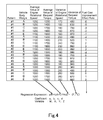
- the regression expression described below is established based on the results from the test runs that have been conducted by the manufacturer of the hybrid vehicle 1 as described above. Using the regression expression makes it possible to calculate a fuel cost improvement effect rate only from the engine rotational speed and the request torque without knowing the amount of loaded cargo and the pattern of running of the hybrid vehicle 1. Note that the fuel cost improvement effect rate is described as (F/E) in Fig. 4 .
- the regeneration control unit 30 is a function for giving the instruction about a regeneration control to the engine ECU 11, the clutch 12, and the electric motor ECU 17 based on the engine rotational speed information, the accelerator opening information, the vehicle speed information, electric motor control information, and the computation formula held in the computation formula holding unit 31.
- step S1 to step S7 in Fig. 3 is a cycle of the process, and is repeatedly performed as long as the key switch 20 is in the ON state.
- step S1 the key switch 20 is in the ON state, the hybrid ECU 18 has executed a computer program, and a function of the regeneration control unit 30 is implemented by the hybrid ECU 18. Then, the process goes to step S1.
- step S1 the regeneration control unit 30 determines from the accelerator opening information and the vehicle speed information whether the hybrid vehicle 1 decelerates. In other words, when the accelerator opening information indicates that the accelerator opening has zero degree, the electric motor control information indicates that the electric motor 13 regenerates electric power, and the vehicle speed information indicates that the vehicle speed decreases, the hybrid vehicle 1 is decelerating. When it is determined in step S1 that the hybrid vehicle 1 is decelerating, the process goes to step S2. On the other hand, when it is determined in step S1 that the hybrid vehicle 1 is not decelerating, step S1 of the process is repeated.
- step S2 the regeneration control unit 30 obtains the engine rotational speed information and the request torque information for a predetermined period of time and calculates the average values and the variances. Then the process goes to step S3. Note that the regeneration control unit 30 obtains the request torque information from the driver according to the accelerator opening information.
- step S3 the regeneration control unit 30 substitutes the average value of the engine rotational speed, the average value of the request torque, the variance of the engine rotational speed, and the variance of the request torque that have been calculated in step S2 into the regression expression that is the computation formula held in the computation formula holding unit 31 (described in Fig. 4 ). Then the process goes to step S4.
- step S4 the regeneration control unit 30 calculates the fuel cost improvement effect rate from the regression expression. Then the process goes to step S5.
- step S5 the regeneration control unit 30 determines whether the fuel cost improvement effect rate is equal to or more than a threshold. When it is determined in step S5 that the fuel cost improvement effect rate is equal to or more than the threshold, the process goes to step S6. On the other hand, when it is determined in step S5 that the fuel cost improvement effect rate is less than the threshold, the process goes to step S7. Note that the threshold will be described below.
- step S6 the regeneration control unit 30 engages the clutch 12 in order to cause the electric motor 13 to regenerate electric power, and terminates a cycle of the process (END).
- step S7 the regeneration control unit 30 disengages the clutch 12 in order to cause the electric motor 13 to regenerate electric power, and terminates a cycle of the process (END).
- the patterns #1, #2, #3, and #4 illustrated in Fig. 4 are the patterns of running of the hybrid vehicle 1.
- the pattern #1 is the run on a public road
- the pattern #2 is the run on an expressway
- the pattern #3 is the run on a congested road
- the pattern #4 is the run on an urban street.
- the vehicle body weights show the gross weight of the hybrid vehicle 1 and are set as A ⁇ B ⁇ C ⁇ D ⁇ E (the unit is a ton or the like).
- the data illustrated in Fig. 4 is the data of a type of vehicle so that the variations of the gross weights are caused, for example, by the variations of the weights of the loaded cargos.
- the various data illustrated in Fig. 4 are the compilations of the average value of the engine rotational speed, the average value of the request torque, the variance of the engine rotational speed, the variance of the request torque, and the fuel cost improvement effect rate at the time when the hybrid vehicle 1 experimentally runs for a predetermined period of time in each of the patterns #1, #2, #3, and #4 with each of the vehicle body weights A, B, C, D, and E.
- a predetermined fuel cost improvement effect rate when a predetermined value is substituted into each of the variables W, X, Y, and Z
- each of the coefficients a, b, c, and d of the regression expression is determined using the various data. Note that a regression expression and the way to establish a regression expression are well-known facts so that the detailed descriptions are omitted.
- the hybrid vehicle 1 holds the regression expression established as described above in the computation formula holding unit 31 of the regeneration control unit 30, obtains the engine rotational speed information and the request torque information (according to the accelerator opening information), calculates the average value of the engine rotational speed, the average value of the request torque, the variance of the engine rotational speed, and the variance of the request torque, and substitutes the values and the variances into the variables W, X, Y, and Z, respectively, so that the hybrid vehicle 1 can calculate a fuel cost improvement effect rate (F/E).
- F/E fuel cost improvement effect rate
- the threshold is set at "zero"
- the vehicle is controlled to perform a clutch-engaged regeneration when the threshold is equal to or more than "zero" or is a positive number exceeding "zero”
- the threshold can variously be set depending on the user's principle for using the vehicle. For example, the threshold is set at "two" and the clutch-engaged regeneration is performed only when the fuel cost improvement effect rate is quite good.
- the clutch 12 is engaged and the electric motor 13 can regenerate electric power during deceleration.
- the efficiency in the regeneration of the electric motor 13 decreases, the fuel consumption of the engine 10 decreases. This can reduce the total of the energy consumption of the hybrid vehicle 1.
- only the engine rotational speed information and the request torque information is required to be substituted into the regression expression. Thus, it is not necessary, for example, to separately attach sensors. This can simplify the structure of the device and save the cost.
- Fig. 5 is a conceptual diagram of a neural network in which the engine rotational speed and the request torque are input and the fuel cost improvement effect rate is output.
- a neural network can be established and be held in the computation formula holding unit 31 of the regeneration control unit 30.
- the neural network is established for calculating a fuel cost improvement effect rate from an engine rotational speed and request torque at the time when the hybrid vehicle 1 experimentally runs for a predetermined period of time in each of the patterns #1, #2, #3, and #4 with each of the vehicle body weights A, B, C, D, and E.
- the way to establish a neural network is well-known fact so that the detailed description is omitted.
- step S2 it is not necessary in the procedure of step S2 in the flowchart of Fig. 3 to calculate the average values and the variances after obtaining the engine rotational speed information and the request torque information for a predetermined period of time.
- "input information into neural network” is performed, instead of the "substitute values into regression expression” in step S3, just after obtaining the engine rotational speed information and the request torque information for a predetermined period of time as the procedure of step S2. This can simplify the process.
- a membership function that is used for a fuzzy inference can also be used instead of the regression expression.
- the membership function is established for calculating a fuel cost improvement effect rate from an engine rotational speed and request torque at the time when the hybrid vehicle 1 experimentally runs for a predetermined period of time in each of the patterns #1, #2, #3, and #4 with each of the vehicle body weights A, B, C, D, and E.
- the way to establish a membership function is well-known fact so that the detailed description is omitted. In that case, it is not necessary in the procedure of step S2 in the flowchart of Fig.
- step S3 calculates the average values and the variances after obtaining the engine rotational speed information and the request torque information for a predetermined period of time.
- "input information into membership function” is performed, instead of the “substitute values into regression expression” in step S3, just after obtaining the engine rotational speed information and the request torque information for a predetermined period of time as the procedure of step S2. This can simplify the process.
- the values of the boundaries for determination can variously be changed, for example, the "equal to or more than” can be changed into “exceeds” and the “less than” can be changed into “equal to or less than” in the description of the flowchart illustrated in Fig. 3 .
- the engine 10 has been described as an internal combustion engine, the engine 10 can also be a heat engine including an external combustion engine.
- the computer program executed by the hybrid ECU 18 is installed on the hybrid ECU 18 in advance in the above-mentioned description
- the computer program can be installed on the hybrid ECU 18 as a computer by attaching removable media recording the computer program (storing the computer program), for example, to a drive (not shown in the drawings) and storing the computer program read from the removable media in a non-volatile memory inside the hybrid ECU 18, or receiving, with a communication unit (not shown in the drawings), a computer program transmitted through a wired or wireless transmission medium and storing the computer program in a non-volatile memory inside the hybrid ECU 18.
- each ECU can be implemented by an ECU combining each of the ECUs.
- an ECU can newly be provided by the further subdivision of the function of each ECU.
- the computer program executed by the computer can be for performing the process in chronological order according to the order described herein or can be for performing the process in parallel or at the necessary timing, for example, when the computer program is invoked.
- embodiments of the present invention are not limited to the above-mentioned embodiments, and can be variously modified without departing from the gist of the invention.
Applications Claiming Priority (2)
| Application Number | Priority Date | Filing Date | Title |
|---|---|---|---|
| JP2011009761 | 2011-01-20 | ||
| PCT/JP2011/074130 WO2012098743A1 (ja) | 2011-01-20 | 2011-10-20 | 回生制御装置、ハイブリッド自動車および回生制御方法、並びにプログラム |
Publications (1)
| Publication Number | Publication Date |
|---|---|
| EP2666689A1 true EP2666689A1 (en) | 2013-11-27 |
Family
ID=46515385
Family Applications (1)
| Application Number | Title | Priority Date | Filing Date |
|---|---|---|---|
| EP11856032.5A Withdrawn EP2666689A1 (en) | 2011-01-20 | 2011-10-20 | Regenerative control device, hybrid automobile, regenerative control method, and program |
Country Status (6)
| Country | Link |
|---|---|
| US (1) | US20130166182A1 (ja) |
| EP (1) | EP2666689A1 (ja) |
| JP (1) | JP5059246B2 (ja) |
| CN (1) | CN103068648B (ja) |
| AU (1) | AU2011355952A1 (ja) |
| WO (1) | WO2012098743A1 (ja) |
Cited By (2)
| Publication number | Priority date | Publication date | Assignee | Title |
|---|---|---|---|---|
| WO2021198342A1 (de) | 2020-04-02 | 2021-10-07 | Zf Friedrichshafen Ag | Verfahren zum betrieb eines hybrid-antriebsstrangs für ein kraftfahrzeug |
| US11753028B1 (en) * | 2022-08-31 | 2023-09-12 | Nissan North America, Inc. | Pedal control system and method for an electric vehicle |
Families Citing this family (10)
| Publication number | Priority date | Publication date | Assignee | Title |
|---|---|---|---|---|
| US10487891B2 (en) * | 2016-02-04 | 2019-11-26 | Ford Global Technologies, Llc | Temperature based clutch control |
| US9457667B2 (en) * | 2011-12-14 | 2016-10-04 | Toyota Jidosha Kabushiki Kaisha | Vehicle control device |
| KR101795378B1 (ko) | 2012-08-07 | 2017-11-09 | 현대자동차 주식회사 | 차량 하중에 기초하여 엔진 토크를 보정하는 방법 및 장치 |
| EP2969688B1 (en) * | 2013-03-14 | 2022-12-21 | Allison Transmission, Inc. | System and method for engine driveline disconnect during regeneration in hybrid vehicles |
| CN103738195B (zh) * | 2013-11-12 | 2016-08-17 | 浙江师范大学 | 一种复合能源电动车能量控制方法 |
| JP5880533B2 (ja) * | 2013-12-13 | 2016-03-09 | トヨタ自動車株式会社 | 車両制御装置 |
| CA2997232C (en) * | 2015-09-01 | 2022-07-26 | Nissan Motor Co., Ltd. | Vehicle traveling control method and vehicle traveling control device |
| JP6753340B2 (ja) * | 2017-03-14 | 2020-09-09 | トヨタ自動車株式会社 | ハイブリッド自動車 |
| CN112739567B (zh) * | 2018-09-21 | 2024-04-09 | 电子能量发动机系统股份有限公司 | 用于功率分割串联电气混合重型车辆的ai控制多通道功率分配器/组合器 |
| US10928275B1 (en) * | 2019-11-18 | 2021-02-23 | Ford Global Technologies, Llc | Systems and methods for coordinating engine-off vehicle diagnostic monitors |
Family Cites Families (40)
| Publication number | Priority date | Publication date | Assignee | Title |
|---|---|---|---|---|
| US4405029A (en) * | 1980-01-02 | 1983-09-20 | Hunt Hugh S | Hybrid vehicles |
| JP3380642B2 (ja) * | 1995-01-18 | 2003-02-24 | 本田技研工業株式会社 | 車両の駆動力演算装置 |
| US5842534A (en) * | 1995-05-31 | 1998-12-01 | Frank; Andrew A. | Charge depletion control method and apparatus for hybrid powered vehicles |
| US6116363A (en) * | 1995-05-31 | 2000-09-12 | Frank Transportation Technology, Llc | Fuel consumption control for charge depletion hybrid electric vehicles |
| US6278986B1 (en) * | 1996-06-27 | 2001-08-21 | Yahama Hatsudoki Kabushiki Kaisha | Integrated controlling system |
| US6032139A (en) * | 1996-09-27 | 2000-02-29 | Yamaha Hatsudoki Kabushiki Kaisha | Electronic controller using genetic evolution techniques suitable for controlling a motor |
| US6324529B1 (en) * | 1996-09-27 | 2001-11-27 | Yamaha Hatsudoki Kabushiki Kaisha | Evolutionary controlling system |
| US6314412B1 (en) * | 1997-09-29 | 2001-11-06 | Yamaha Hatsudoki Kabushiki Kaisha | Evolutionary control of machine based on user's preference inferred from user's operation |
| JPH11327606A (ja) * | 1998-05-14 | 1999-11-26 | Yamaha Motor Co Ltd | 総合制御方式 |
| US6466859B1 (en) * | 1998-06-04 | 2002-10-15 | Yamaha Motor Co Ltd | Control system |
| JP2000020103A (ja) * | 1998-07-02 | 2000-01-21 | Yamaha Motor Co Ltd | 遺伝的アルゴリズムの評価方法 |
| JP2000054862A (ja) * | 1998-08-07 | 2000-02-22 | Yamaha Motor Co Ltd | 動力源付き乗物における出力制御方法 |
| US6554088B2 (en) * | 1998-09-14 | 2003-04-29 | Paice Corporation | Hybrid vehicles |
| US6079204A (en) * | 1998-09-21 | 2000-06-27 | Ford Global Technologies, Inc. | Torque control for direct injected engines using a supplemental torque apparatus |
| US6321157B1 (en) * | 1999-04-27 | 2001-11-20 | Ford Global Technologies, Inc. | Hybrid modeling and control of disc engines |
| JP2001159903A (ja) * | 1999-12-01 | 2001-06-12 | Yamaha Motor Co Ltd | 組合せ完成品用単位装置の最適化装置 |
| US6304812B1 (en) * | 2000-04-28 | 2001-10-16 | Ford Global Technologies, Inc. | Calibration optimization method |
| US6363317B1 (en) * | 2000-08-26 | 2002-03-26 | Ford Global Technologies, Inc. | Calibration method for disc engines |
| US7084602B2 (en) * | 2004-02-17 | 2006-08-01 | Railpower Technologies Corp. | Predicting wheel slip and skid in a locomotive |
| DE102004026583B3 (de) * | 2004-05-28 | 2005-11-24 | Robert Bosch Gmbh | Verfahren zur Optimierung von Kennfeldern |
| US7940016B2 (en) * | 2004-08-09 | 2011-05-10 | Railpower, Llc | Regenerative braking methods for a hybrid locomotive |
| US7304445B2 (en) * | 2004-08-09 | 2007-12-04 | Railpower Technologies Corp. | Locomotive power train architecture |
| EP2275946A1 (en) * | 2005-03-04 | 2011-01-19 | STMicroelectronics S.r.l. | Probabilistic neural network and relative training method |
| JP4175370B2 (ja) * | 2006-01-13 | 2008-11-05 | トヨタ自動車株式会社 | ハイブリッド車両およびその制御方法 |
| JP4348557B2 (ja) | 2006-02-22 | 2009-10-21 | 三菱ふそうトラック・バス株式会社 | ハイブリッド電気自動車の制御装置 |
| JP4571917B2 (ja) * | 2006-02-22 | 2010-10-27 | 本田技研工業株式会社 | ハイブリッド車両の制御装置 |
| US20070233326A1 (en) * | 2006-03-31 | 2007-10-04 | Caterpillar Inc. | Engine self-tuning methods and systems |
| US7826939B2 (en) * | 2006-09-01 | 2010-11-02 | Azure Dynamics, Inc. | Method, apparatus, signals, and medium for managing power in a hybrid vehicle |
| US7832511B2 (en) * | 2006-10-20 | 2010-11-16 | Ford Global Technologies | Hybrid electric vehicle control system and method of use |
| JP4380700B2 (ja) * | 2006-12-29 | 2009-12-09 | トヨタ自動車株式会社 | 電動車両 |
| JP4229185B2 (ja) * | 2007-01-12 | 2009-02-25 | トヨタ自動車株式会社 | ハイブリッド自動車およびその制御方法 |
| US7849944B2 (en) * | 2007-06-12 | 2010-12-14 | Ut-Battelle, Llc | Self-learning control system for plug-in hybrid vehicles |
| US9002550B2 (en) * | 2007-07-02 | 2015-04-07 | GM Global Technology Operations LLC | Use of torque model at virtual engine conditions |
| US8108136B2 (en) * | 2007-08-09 | 2012-01-31 | Ford Global Technologies, Llc. | Driver advisory system for fuel economy improvement of a hybrid electric vehicle |
| US7593804B2 (en) * | 2007-10-31 | 2009-09-22 | Caterpillar Inc. | Fixed-point virtual sensor control system and method |
| TWI346056B (en) * | 2007-12-07 | 2011-08-01 | Ind Tech Res Inst | Mixed type vehicle power system and method of forming multidimentional data of fuel consumption |
| US7954579B2 (en) * | 2008-02-04 | 2011-06-07 | Illinois Institute Of Technology | Adaptive control strategy and method for optimizing hybrid electric vehicles |
| US20090259355A1 (en) * | 2008-04-15 | 2009-10-15 | The Uwm Research Foundation, Inc. | Power management of a hybrid vehicle |
| JP5133197B2 (ja) * | 2008-10-15 | 2013-01-30 | 日野自動車株式会社 | ハイブリッド自動車およびコンピュータ装置ならびにプログラム |
| JP5136686B2 (ja) * | 2009-04-13 | 2013-02-06 | トヨタ自動車株式会社 | 駆動力制御装置 |
-
2011
- 2011-10-20 JP JP2012514260A patent/JP5059246B2/ja not_active Expired - Fee Related
- 2011-10-20 AU AU2011355952A patent/AU2011355952A1/en not_active Abandoned
- 2011-10-20 WO PCT/JP2011/074130 patent/WO2012098743A1/ja active Application Filing
- 2011-10-20 EP EP11856032.5A patent/EP2666689A1/en not_active Withdrawn
- 2011-10-20 US US13/819,449 patent/US20130166182A1/en not_active Abandoned
- 2011-10-20 CN CN201180040644.8A patent/CN103068648B/zh not_active Expired - Fee Related
Non-Patent Citations (1)
| Title |
|---|
| See references of WO2012098743A1 * |
Cited By (3)
| Publication number | Priority date | Publication date | Assignee | Title |
|---|---|---|---|---|
| WO2021198342A1 (de) | 2020-04-02 | 2021-10-07 | Zf Friedrichshafen Ag | Verfahren zum betrieb eines hybrid-antriebsstrangs für ein kraftfahrzeug |
| DE102020204284A1 (de) | 2020-04-02 | 2021-10-07 | Zf Friedrichshafen Ag | Verfahren zum Betrieb eines Hybrid-Antriebsstrangs für ein Kraftfahrzeug |
| US11753028B1 (en) * | 2022-08-31 | 2023-09-12 | Nissan North America, Inc. | Pedal control system and method for an electric vehicle |
Also Published As
| Publication number | Publication date |
|---|---|
| WO2012098743A1 (ja) | 2012-07-26 |
| JP5059246B2 (ja) | 2012-10-24 |
| US20130166182A1 (en) | 2013-06-27 |
| CN103068648A (zh) | 2013-04-24 |
| JPWO2012098743A1 (ja) | 2014-06-09 |
| AU2011355952A1 (en) | 2013-05-09 |
| CN103068648B (zh) | 2015-09-09 |
Similar Documents
| Publication | Publication Date | Title |
|---|---|---|
| EP2666689A1 (en) | Regenerative control device, hybrid automobile, regenerative control method, and program | |
| US9139196B2 (en) | Regenerative control device, hybrid vehicle, regenerative control method, and computer program | |
| EP2631145B1 (en) | Start control method, start control device, hybrid automobile, and program | |
| EP2664511A1 (en) | Regeneration control device, hybrid automobile, regeneration control method, and program | |
| EP2666691A1 (en) | Regeneration control device, hybrid automobile, regeneration control method, and program | |
| JP5073875B2 (ja) | 車両および制御方法、並びにプログラム | |
| US8694190B2 (en) | Regeneration control device, hybrid vehicle, regeneration control method, and computer program | |
| JP5001475B1 (ja) | 回生制御装置、ハイブリッド自動車および回生制御方法、並びにプログラム | |
| US8989934B2 (en) | Regeneration control device, hybrid vehicle, regeneration control method, and computer program | |
| US20130179022A1 (en) | Regeneration control device, hybrid vehicle, regeneration control method, and program | |
| EP2631146B1 (en) | Vehicle, control method, and program | |
| JP2013220663A (ja) | ハイブリッド自動車の制御装置、ハイブリッド自動車、およびハイブリッド自動車の制御方法、並びにプログラム |
Legal Events
| Date | Code | Title | Description |
|---|---|---|---|
| PUAI | Public reference made under article 153(3) epc to a published international application that has entered the european phase |
Free format text: ORIGINAL CODE: 0009012 |
|
| 17P | Request for examination filed |
Effective date: 20130225 |
|
| AK | Designated contracting states |
Kind code of ref document: A1 Designated state(s): AL AT BE BG CH CY CZ DE DK EE ES FI FR GB GR HR HU IE IS IT LI LT LU LV MC MK MT NL NO PL PT RO RS SE SI SK SM TR |
|
| DAX | Request for extension of the european patent (deleted) | ||
| STAA | Information on the status of an ep patent application or granted ep patent |
Free format text: STATUS: THE APPLICATION IS DEEMED TO BE WITHDRAWN |
|
| 18D | Application deemed to be withdrawn |
Effective date: 20160503 |