EP2666518A2 - Blockiervorrichtung für Laufleine mit beweglichem Drehkörper - Google Patents
Blockiervorrichtung für Laufleine mit beweglichem Drehkörper Download PDFInfo
- Publication number
- EP2666518A2 EP2666518A2 EP13354017.9A EP13354017A EP2666518A2 EP 2666518 A2 EP2666518 A2 EP 2666518A2 EP 13354017 A EP13354017 A EP 13354017A EP 2666518 A2 EP2666518 A2 EP 2666518A2
- Authority
- EP
- European Patent Office
- Prior art keywords
- lanyard
- groove
- hole
- blocker
- passage
- Prior art date
- Legal status (The legal status is an assumption and is not a legal conclusion. Google has not performed a legal analysis and makes no representation as to the accuracy of the status listed.)
- Granted
Links
Images


Classifications
-
- A—HUMAN NECESSITIES
- A62—LIFE-SAVING; FIRE-FIGHTING
- A62B—DEVICES, APPARATUS OR METHODS FOR LIFE-SAVING
- A62B35/00—Safety belts or body harnesses; Similar equipment for limiting displacement of the human body, especially in case of sudden changes of motion
-
- A—HUMAN NECESSITIES
- A62—LIFE-SAVING; FIRE-FIGHTING
- A62B—DEVICES, APPARATUS OR METHODS FOR LIFE-SAVING
- A62B1/00—Devices for lowering persons from buildings or the like
- A62B1/06—Devices for lowering persons from buildings or the like by making use of rope-lowering devices
- A62B1/14—Devices for lowering persons from buildings or the like by making use of rope-lowering devices with brakes sliding on the rope
-
- A—HUMAN NECESSITIES
- A63—SPORTS; GAMES; AMUSEMENTS
- A63B—APPARATUS FOR PHYSICAL TRAINING, GYMNASTICS, SWIMMING, CLIMBING, OR FENCING; BALL GAMES; TRAINING EQUIPMENT
- A63B29/00—Apparatus for mountaineering
- A63B29/02—Mountain guy-ropes or accessories, e.g. avalanche ropes; Means for indicating the location of accidentally buried, e.g. snow-buried, persons
Definitions
- the invention relates to a lanyard locker with a body movable in rotation, and in particular a lanyard blocker for attaching an element to a fixed attachment point.
- the invention particularly relates to a lanyard blocker for providing a user with a fixed wall in the field of mountaineering, climbing, caving, or work at height.
- a lanyard can be used to ensure a fixed wall.
- a lanyard consists of a rope generally provided, at at least one end, with a hooking ring, for example a carabiner, to ensure a ring fixed to the wall, the other end being connected to the climber.
- a hooking ring for example a carabiner
- These lanyards can also be used to attach any type of equipment. But the length of these lanyards is not adjustable.
- rope blockers such as insurers marketed by the company CAMP, used to ensure the ascension of a climber by another person who is on the ground.
- a blocker comprises a through hole for the passage of a carabiner and a groove opening into the first hole for a passage of the rope through the hole and through the carabiner.
- the carabiner is also attached to the harness of the person on the ground who assures the climber.
- the rope can be locked by wedging it between the carabiner and the blocker.
- the insurer approaches the two strands of the rope, one towards the other, and rotates the blocker to release the carabiner and thus unlock the rope. But when the rope is slid to give slack to the climber, the rope rubs against the carabiner, and causes wear of it.
- the object of the invention is to overcome these disadvantages, and more particularly to achieve a simple and lightweight lanyard blocker.
- a lanyard blocker having a body provided with a through hole for the passage of a hooking ring and a curved groove opening into the through hole for the passage of the lanyard through the ring, the body being movable in rotation between a locking position in which the lanyard is locked by the ring against the body and an unlocking position in which the lanyard slides in the groove.
- the groove comprises a deflection element to allow, in unlocking position, a sliding of the lanyard in the groove and outside the through hole.
- the deflection element is a wall separating the interior of the through-hole and the interior of the groove to allow, in the unlocking position, the fastening ring to bear against the deflection element so as to that the long slide without rubbing against the snap ring.
- Such a blocker allows a locking of the effective lanyard, while allowing to adjust the length of the lanyard under load.
- a blocker makes it possible to slide the lanyard so that it can not rub against the snap ring, in order to avoid untimely wear of the lanyard. lanyard.
- Such a blocker is particularly suitable for making sure at a fixed point.
- the groove can be configured to exert friction on the lanyard so as to allow the body to tilt from one position to the other.
- the groove may comprise a first orifice for passage of the lanyard inside the body, a second orifice opening into the through hole and a third orifice for a passage of the lanyard outside the body, the first and third openings. being separated by a separating member of the body, the separating member allowing by leverage the passage of the body in the unlocking position when the lanyard bears against the separating element.
- the groove may further comprise an opening facing outwardly of the body and located between the first and second orifices of the groove.
- Such an opening allows access to the portion of the lanyard that passes into the groove, in particular to facilitate the sliding of the lanyard in the body of the blocker.
- the body may be provided with a pulley located between the first and second ports of the groove.
- the body may also include a handle to facilitate rotation of the body.
- the handle may comprise at least a portion partially covering the through hole so as to bear against the attachment ring to reduce the effort in the handle through a reduction effect.
- the two strands of the lanyard can be attached to the same element.
- the body can be made from a single piece, preferably metal, and for example aluminum.
- the body can also be made from two sheets held together by rivets.
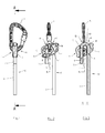
- FIG 1 schematically a perspective view of a blocker 1 of lanyard 2 having a body 3 provided with a through hole 4 for the passage of a fastening ring 5, for example a shackle and preferably a carabiner.
- the body 3 of the blocker 1 is preferably metallic and may be made of cut sheet metal, stamped and folded or forge, or machined in a metal block.
- the carabiner 5 is hooked to a fixed point, such as an anchoring ring fixed to a wall or any other fixed element, and at least one strand 6, 7 of the lanyard is attached to an object which is want to hang up at the fixed point.
- the object may be a bag, or any other type of equipment, or a user, for example via a shoulder belt.
- the blocker 1 makes it possible to block the lanyard 2 in order to secure the attachment of the user, or equipment, while offering the possibility to adjust the length of the lanyard, in particular to adjust the distance between the end of the lanyard strand 6 which is attached to the object and the carabiner 5.
- the body 3 of the blocker 1 is rotatable between an unlocking position illustrated in FIGS. Figures 2 and 3 and a blocking position illustrated at Figures 4, 5 , 7 and 8 .
- FIG. 2 and 3 schematically shows an anterior view of the blocker 1 of lanyard 2 in the unlocking position.
- figure 3 is a sectional view along the axis AA of the figure 1 .
- the body 3 of the blocker 1 further comprises a groove 9 to guide the lanyard inside the body 3, so that the lanyard 2 passes through the through hole 4 and through the carabiner 5.
- the groove 9 allows a sliding of the lanyard 2 outside the through hole 4, in other words around the through hole 4.
- the groove 9 has a first hole 11 for a passage of the lanyard inside the body 3, a second orifice 10 opening into the through hole 4 and a third orifice 8 opening towards the outside of the body 3.
- the groove 9 has a portion 18 located between the first and second orifices 11, 10 of the groove 9.
- the portion 18 is curved towards the through hole 4.
- the groove 9 has a global shape in U.
- the through hole 4 and the openings 11, 10, 8 of the groove 9 have a generally cylindrical shape.
- the through hole 4 may have an ovoid shape.
- the through hole 4 comprises a main axis oriented substantially perpendicular to the longitudinal plane of the body 3 (that is to say, the cutting plane along the axis AA).
- the first, second and third ports 11, 10, 8 are oriented, in turn, substantially perpendicular to the through hole 4.
- the lanyard 2 enters the body 3 through the first orifice 11, passes into the curved portion 18 of the groove 9, passes through the second orifice 10, and passes inside the through hole 4 in a direction perpendicular to the main axis of the through hole 4.
- the lanyard 2 passes through the third orifice 8 of the groove 9 to exit the body 3 of the blocker 1.
- the groove 9 is oriented so that the lanyard 2 passes around the through hole 4.
- the curved portion 18 of the groove 9 comprises a deflection element 12.
- the deflection element 12 may be a wall separating the interior of the through hole 4 and the inside of the curved portion 18 of the groove 9.
- the wall forms a bearing surface 12 located between the lanyard 2 and the carabiner 5.
- the support surface 12 is located opposite the interior of the through hole 4.
- the curved portion 18 can be fully closed within the body 3 along its length and open only at the first and second orifices 11, 10.
- the curved portion 18 of the groove 9 may include an opening 13 facing outwardly of the body 3 to access to 2, in particular to facilitate the sliding of the lanyard 2 in the groove 9.
- the third orifice 8 and the first orifice 11 of the groove 9 are situated on one and the same face of the body 3, and on either side of the through-hole 4.
- the body 3 can comprise a separation element 14 located between the third orifice 8 and the first orifice 11 of the groove 9.
- the body 3 may comprise a single orifice forming both the first and third orifices 11, 8 of the groove 9. In this variant, the body 3 does not include such a separating element 14.
- the body 3 of the blocker 1 is rotatable about the main axis of the through hole 4, that is to say in rotation about an axis of rotation substantially perpendicular to the through hole 4.
- the body 3 is movable in rotation between a locking position in which the lanyard 2 is locked by the carabiner 5 against the body 3 and an unlocking position in which the lanyard 2 slides in the groove 9.
- the lanyard 2 slides in the groove 9 of the body 3 of the blocker 1, in particular in the curved portion 18 of the groove 9 and through the third orifice 8.
- the user can slide the loin 2 pulling on one of the strands 6, 7 thereof.
- the sliding can also be facilitated by the deflection element 12.
- the deflection element 12 allows, in particular, to slide the lanyard 2 when a weight is attached to the end of the other strand referenced 6, also noted safety strand.
- the length of the safety strand 6 between the weight and the carabiner 5 is shortened. It is also possible to lengthen the length of the safety strand 6, releasing the tension on the soft strand 7, while maintaining the body 3 in the unlocking position, and by pulling the safety strand 6. It is thus possible to adjust the length of the lanyard 2. In other words, it can shorten the length of the safety strand 6 when it is in tension , that is to say in load, by pulling on the soft strand 7. The length of the safety strand 6 can be lengthened when it is no longer in tension.
- the lengths of the two strands 6, 7 of the loin 2 can also be adjusted by removing the weight at each end of the strands 6, 7 so that each strand 6, 7 is no longer under tension.
- the deflection element 12 makes it possible to slide the lanyard 2 while preventing it from rubbing against the carabiner 5.
- FIG. 4 and 5 schematically shows an anterior view of the blocker 1 of lanyard 2 in the locking position.
- figure 5 is a sectional view along the axis AA of the figure 1 .
- the carabiner 5 wedges the lanyard 2 against the body 3 of the blocker 1, in particular against an edge of the through hole 4 which is situated between the third orifice 8 and the second orifice 10 of the groove 9.
- the carabiner 5 is located facing the deflection element 12 and does not bear against it.
- the lanyard 2 does not slide, and the safety strand 6 is in tension and ensures an attachment of an object to the anchor ring safely.
- the soft strand 7 may or may not be attached to the object because the latter is not put in tension.
- the rotation of the body 3 of the blocker 1 allows the passage between the locking position and the unlocking position and vice versa.
- the user pulls on the soft strand 7 of the lanyard 2, and the body 3 tilts while bearing against the carabiner 5 at the deflection element 12.
- 3 rotates about its axis of rotation to the unlocking position in which the carabiner 5 is in abutment against the deflection element 12 and does not wedge the longer the lanyard 2 against the body 3.
- the rotation of the body 3 releases the carabiner 5 which is no longer in contact with the lanyard 2.
- the lanyard 2 slides without rubbing against the carabiner 5, which limit the wear of the lanyard 2.
- the rotation of the body 3 to move to the unlocking position can be performed under full load, that is to say with the safety strand 6 in tension.
- the groove 9 creates a baffle for the lanyard 2, and generates friction on the lanyard 2 to facilitate the rotation of the body 3 from one position to another.
- the deflection element 12 allows a first lever effect which cooperates with the friction generated by the groove 9 on the lanyard 2, to facilitate the tilting of the body 3 in the locking position.
- the separating element 14 facilitates the passage into the unlocking position by allowing the soft strand 7 to be supported on the separating element 14 to create a second inverse lever effect to the first.
- the body 3 automatically topples while bearing against the carabiner 5, at the deflection element 12 of the groove 9, by the effect of the weight which keeps the safety strand 6 in tension.
- the body 3 rotates about its axis of rotation to the locking position in which the carabiner 5 is in support against the loin 2 and wedges it against the body 3.
- the body 3 comprises a pulley 15 located in the groove 9, in particular in the curved portion 18, in order to facilitate the sliding of the lanyard 2.
- the blocker 1 has a handle 16 in protruding body 3 to facilitate its rotation.
- the handle 16 is located on the side of the third orifice 8, that is to say on the side of the soft strand 7.
- the handle 16 comprises a portion 17 which partially covers the through hole 4 so as to bear against the carabiner 5 to increase the forces applied to the carabiner 5 by the body 3 during the rotation of the latter.
- the body 3 of the blocker is made from two sheets 3a, 3b held together by rivets 12, 14, 20 to 23.
- the body 3 may comprise two rivets 20, 21 respectively at the ends of the body 3.
- the rivet referenced 12 forms the deflection element.
- the deflection element 12 may be a generally cylindrical rod.
- the body 3 may comprise a rivet referenced 14 forming the separating element.
- the groove 9 may comprise an additional opening 24 for communication between the interior of the through hole 4 and the inside of the groove 9. The additional opening 24 is located between the deflection element 12 and the element separation 14.
- an adjustable tether locker configured to hook any type of object to a fixed point while allowing the length of the lanyard to be adjusted.
- a blocker is simple to use and is particularly compact.
Landscapes
- Health & Medical Sciences (AREA)
- General Health & Medical Sciences (AREA)
- Business, Economics & Management (AREA)
- Emergency Management (AREA)
- Pulmonology (AREA)
- Physical Education & Sports Medicine (AREA)
- Emergency Lowering Means (AREA)
- Lock And Its Accessories (AREA)
Applications Claiming Priority (1)
| Application Number | Priority Date | Filing Date | Title |
|---|---|---|---|
| FR1201446A FR2990873B1 (fr) | 2012-05-22 | 2012-05-22 | Bloqueur de longe a corps mobile en rotation |
Publications (3)
| Publication Number | Publication Date |
|---|---|
| EP2666518A2 true EP2666518A2 (de) | 2013-11-27 |
| EP2666518A3 EP2666518A3 (de) | 2014-07-16 |
| EP2666518B1 EP2666518B1 (de) | 2023-10-11 |
Family
ID=48613548
Family Applications (1)
| Application Number | Title | Priority Date | Filing Date |
|---|---|---|---|
| EP13354017.9A Active EP2666518B1 (de) | 2012-05-22 | 2013-05-21 | Blockiervorrichtung für Laufleine mit beweglichem Drehkörper |
Country Status (7)
| Country | Link |
|---|---|
| US (1) | US9227092B2 (de) |
| EP (1) | EP2666518B1 (de) |
| CN (1) | CN103418114B (de) |
| ES (1) | ES2961858T3 (de) |
| FR (1) | FR2990873B1 (de) |
| RU (1) | RU2622818C2 (de) |
| TW (1) | TWI592193B (de) |
Cited By (2)
| Publication number | Priority date | Publication date | Assignee | Title |
|---|---|---|---|---|
| IT202100014612A1 (it) | 2021-06-04 | 2022-12-04 | Aludesign Spa | Dispositivo bloccante/ frenante per la regolazione di una fune di sicurezza |
| US20240408420A1 (en) * | 2021-10-04 | 2024-12-12 | Aludesign S.P.A. | Multifunction device equipped with a locking cam and a pulley for a safety rope |
Families Citing this family (7)
| Publication number | Priority date | Publication date | Assignee | Title |
|---|---|---|---|---|
| IT1403628B1 (it) * | 2011-01-13 | 2013-10-31 | Aludesign Spa | Dispositivo assicuratore e discensore |
| US9427606B2 (en) * | 2013-08-02 | 2016-08-30 | Atlas Devices, Llc | Descent assist device for powered ascenders |
| US10987525B2 (en) * | 2017-05-22 | 2021-04-27 | Cmc Rescue, Inc. | Descending apparatus and methods for use of same |
| IT201800001896A1 (it) * | 2018-01-25 | 2019-07-25 | Aludesign Spa | Dispositivo assicuratore |
| US11141621B2 (en) * | 2020-03-02 | 2021-10-12 | T2 Fitness Products, Inc. | Combined friction resistance and elastic resistance exercise device |
| RU210294U1 (ru) * | 2021-04-16 | 2022-04-06 | Геннадий Анатольевич Дульцев | Страховочно-спусковое устройство для использования в туризме, альпинизме, промышленных работах и спасательных работах |
| WO2026002776A1 (en) | 2024-06-26 | 2026-01-02 | Mammut Sports Group Ag | Rope blocker having a rotating cam, and a corresponding rope blocking method |
Family Cites Families (16)
| Publication number | Priority date | Publication date | Assignee | Title |
|---|---|---|---|---|
| AT392592B (de) * | 1988-08-17 | 1991-04-25 | Prohaska Heinz | Selbstblockierendes abseilgeraet |
| RU3094U1 (ru) * | 1995-08-07 | 1996-11-16 | Борис Лазаревич Кашевник | Устройство для спуска по веревке |
| FR2748078B1 (fr) * | 1996-04-25 | 1998-06-12 | Zedel | Poulie a flasque pivotant et a bloqueur integre |
| AUPQ467299A0 (en) * | 1999-12-15 | 2000-01-13 | Rogelja, Boris | Descender with two-way locking lever |
| US6561313B2 (en) * | 2001-08-16 | 2003-05-13 | Trimorphics, Inc. | Belay/rappel device for use in climbing activities and the like |
| WO2006035138A1 (fr) * | 2004-09-24 | 2006-04-06 | Franck Gressier | Dispositif assureur descendeur autobloquant pour cordes de tout diametre |
| FR2898506B1 (fr) * | 2006-03-15 | 2008-05-30 | Zedel Soc Par Actions Simplifi | Appareil multifonctionnel d'assurage pour corde |
| US20080245611A1 (en) * | 2007-04-07 | 2008-10-09 | Gregory Lee Klingler | Self-Belay And Rappel Device And Methods Of Use |
| US20080302600A1 (en) * | 2007-06-11 | 2008-12-11 | Richard Murray | Descent control device |
| FR2919196B1 (fr) * | 2007-07-26 | 2009-10-09 | Zedel Soc Par Actions Simplifi | Descendeur autobloquant a poignee debrayable. |
| WO2010088566A1 (en) * | 2009-02-02 | 2010-08-05 | Ayre William H | Rope handling device with secondary locking feature |
| IT1396181B1 (it) * | 2009-07-15 | 2012-11-16 | Aludesign Spa | Dispositivo assicuratore |
| CH701645B1 (de) * | 2010-05-19 | 2011-02-28 | Mammut Sports Group Ag | Sicherungsgerät zur Sicherung von Seilen |
| ITMO20100200A1 (it) * | 2010-07-02 | 2012-01-03 | Milano Politecnico | Dispositivo di sicurezza per corde |
| CN202128858U (zh) * | 2011-07-20 | 2012-02-01 | 湛江市玛雅旅游用品有限公司 | 一种自锁攀登保护器及自锁攀登保护装置 |
| US9138603B2 (en) * | 2012-02-23 | 2015-09-22 | Honeywell International Inc. | Rope adjuster with fast rope replacement device |
-
2012
- 2012-05-22 FR FR1201446A patent/FR2990873B1/fr active Active
-
2013
- 2013-05-21 RU RU2013123294A patent/RU2622818C2/ru active
- 2013-05-21 TW TW102117820A patent/TWI592193B/zh active
- 2013-05-21 ES ES13354017T patent/ES2961858T3/es active Active
- 2013-05-21 US US13/898,831 patent/US9227092B2/en active Active
- 2013-05-21 EP EP13354017.9A patent/EP2666518B1/de active Active
- 2013-05-22 CN CN201310328873.0A patent/CN103418114B/zh active Active
Non-Patent Citations (1)
| Title |
|---|
| None |
Cited By (2)
| Publication number | Priority date | Publication date | Assignee | Title |
|---|---|---|---|---|
| IT202100014612A1 (it) | 2021-06-04 | 2022-12-04 | Aludesign Spa | Dispositivo bloccante/ frenante per la regolazione di una fune di sicurezza |
| US20240408420A1 (en) * | 2021-10-04 | 2024-12-12 | Aludesign S.P.A. | Multifunction device equipped with a locking cam and a pulley for a safety rope |
Also Published As
| Publication number | Publication date |
|---|---|
| ES2961858T3 (es) | 2024-03-14 |
| US9227092B2 (en) | 2016-01-05 |
| TW201410299A (zh) | 2014-03-16 |
| RU2622818C2 (ru) | 2017-06-20 |
| CN103418114A (zh) | 2013-12-04 |
| EP2666518B1 (de) | 2023-10-11 |
| CN103418114B (zh) | 2016-12-28 |
| FR2990873A1 (fr) | 2013-11-29 |
| EP2666518A3 (de) | 2014-07-16 |
| TWI592193B (zh) | 2017-07-21 |
| RU2013123294A (ru) | 2014-11-27 |
| US20130313047A1 (en) | 2013-11-28 |
| FR2990873B1 (fr) | 2016-12-09 |
Similar Documents
| Publication | Publication Date | Title |
|---|---|---|
| EP2666518B1 (de) | Blockiervorrichtung für Laufleine mit beweglichem Drehkörper | |
| EP0803268B1 (de) | Scheibe mit Drehflansch und integrierter Klemme | |
| EP0752255B1 (de) | Bewegliches Absturzsicherungsgerät für flexibles Rettungsseil | |
| EP0608164B1 (de) | Bewegliche Verankerung die eine sichere waagerechte Verschiebung ermöglicht | |
| EP2735341B1 (de) | Seilsicherungsgerät mit Verschlussmöglichkeit unter Belastung | |
| EP1359980B1 (de) | Bewegliches absturzsicherungsgerät für rettungsseil | |
| EP2131927A2 (de) | Relais und/oder abseilungszubehör | |
| FR2505309A1 (fr) | Dispositif permettant de freiner et/ou d'immobiliser une charge, notamment dispositif de securite anti-chute | |
| EP3659675A2 (de) | Sicherungsvorrichtung | |
| EP3919139B1 (de) | Seilgurt | |
| EP0757580B1 (de) | Selbstblockierende abseilvorrichtung | |
| FR2957812A1 (fr) | Descendeur auto-bloquant sur filin tendu a points de friction variables | |
| EP1329242A1 (de) | Selbstblockierende Abseilvorrichtung auf gespannte Seile | |
| FR3112370A1 (fr) | Dispositif porte-materiel | |
| EP3421098B1 (de) | Verbessertes abseilgerät | |
| EP3924070B1 (de) | Verbinder, lösbare gabelattrappe mit einem solchen verbinder und betriebsverfahren | |
| FR2632196A1 (fr) | Descendeur autobloquant | |
| FR3022465A1 (fr) | Dispositif d'assurage et de rappel a encoche de blocage | |
| FR2812336A1 (fr) | Dispositif du type echelle a securite renforcee | |
| EP3699361B1 (de) | Rückhaltesystem mit entfernbarem stab mit auf- und abwickelvorrichtung zur absturzsicherung für zugangsschächte | |
| FR2884429A1 (fr) | Dispositif de freinage et blocage de corde | |
| WO1994008147A1 (fr) | Mousqueton de surete pour l'escalade | |
| FR2814082A1 (fr) | Dispositif de securite pour controler la descente et/ou le hissage d'une charge sur une corde | |
| WO2023156881A1 (fr) | Mousqueton d'attache | |
| FR3134728A1 (fr) | Descendeur ameliore |
Legal Events
| Date | Code | Title | Description |
|---|---|---|---|
| PUAI | Public reference made under article 153(3) epc to a published international application that has entered the european phase |
Free format text: ORIGINAL CODE: 0009012 |
|
| AK | Designated contracting states |
Kind code of ref document: A2 Designated state(s): AL AT BE BG CH CY CZ DE DK EE ES FI FR GB GR HR HU IE IS IT LI LT LU LV MC MK MT NL NO PL PT RO RS SE SI SK SM TR |
|
| AX | Request for extension of the european patent |
Extension state: BA ME |
|
| PUAL | Search report despatched |
Free format text: ORIGINAL CODE: 0009013 |
|
| AK | Designated contracting states |
Kind code of ref document: A3 Designated state(s): AL AT BE BG CH CY CZ DE DK EE ES FI FR GB GR HR HU IE IS IT LI LT LU LV MC MK MT NL NO PL PT RO RS SE SI SK SM TR |
|
| AX | Request for extension of the european patent |
Extension state: BA ME |
|
| RIC1 | Information provided on ipc code assigned before grant |
Ipc: A62B 1/14 20060101AFI20140610BHEP Ipc: A63B 29/02 20060101ALI20140610BHEP |
|
| 17P | Request for examination filed |
Effective date: 20150114 |
|
| RBV | Designated contracting states (corrected) |
Designated state(s): AL AT BE BG CH CY CZ DE DK EE ES FI FR GB GR HR HU IE IS IT LI LT LU LV MC MK MT NL NO PL PT RO RS SE SI SK SM TR |
|
| STAA | Information on the status of an ep patent application or granted ep patent |
Free format text: STATUS: EXAMINATION IS IN PROGRESS |
|
| 17Q | First examination report despatched |
Effective date: 20190226 |
|
| GRAP | Despatch of communication of intention to grant a patent |
Free format text: ORIGINAL CODE: EPIDOSNIGR1 |
|
| STAA | Information on the status of an ep patent application or granted ep patent |
Free format text: STATUS: GRANT OF PATENT IS INTENDED |
|
| INTG | Intention to grant announced |
Effective date: 20230228 |
|
| RIN1 | Information on inventor provided before grant (corrected) |
Inventor name: CHAUMONTET, MICHAEL |
|
| GRAJ | Information related to disapproval of communication of intention to grant by the applicant or resumption of examination proceedings by the epo deleted |
Free format text: ORIGINAL CODE: EPIDOSDIGR1 |
|
| STAA | Information on the status of an ep patent application or granted ep patent |
Free format text: STATUS: EXAMINATION IS IN PROGRESS |
|
| GRAP | Despatch of communication of intention to grant a patent |
Free format text: ORIGINAL CODE: EPIDOSNIGR1 |
|
| STAA | Information on the status of an ep patent application or granted ep patent |
Free format text: STATUS: GRANT OF PATENT IS INTENDED |
|
| INTC | Intention to grant announced (deleted) | ||
| INTG | Intention to grant announced |
Effective date: 20230524 |
|
| GRAS | Grant fee paid |
Free format text: ORIGINAL CODE: EPIDOSNIGR3 |
|
| GRAA | (expected) grant |
Free format text: ORIGINAL CODE: 0009210 |
|
| STAA | Information on the status of an ep patent application or granted ep patent |
Free format text: STATUS: THE PATENT HAS BEEN GRANTED |
|
| AK | Designated contracting states |
Kind code of ref document: B1 Designated state(s): AL AT BE BG CH CY CZ DE DK EE ES FI FR GB GR HR HU IE IS IT LI LT LU LV MC MK MT NL NO PL PT RO RS SE SI SK SM TR |
|
| REG | Reference to a national code |
Ref country code: GB Ref legal event code: FG4D Free format text: NOT ENGLISH |
|
| REG | Reference to a national code |
Ref country code: CH Ref legal event code: EP |
|
| REG | Reference to a national code |
Ref country code: DE Ref legal event code: R096 Ref document number: 602013084777 Country of ref document: DE |
|
| REG | Reference to a national code |
Ref country code: IE Ref legal event code: FG4D Free format text: LANGUAGE OF EP DOCUMENT: FRENCH |
|
| REG | Reference to a national code |
Ref country code: LT Ref legal event code: MG9D |
|
| REG | Reference to a national code |
Ref country code: NL Ref legal event code: MP Effective date: 20231011 |
|
| REG | Reference to a national code |
Ref country code: ES Ref legal event code: FG2A Ref document number: 2961858 Country of ref document: ES Kind code of ref document: T3 Effective date: 20240314 |
|
| REG | Reference to a national code |
Ref country code: AT Ref legal event code: MK05 Ref document number: 1619631 Country of ref document: AT Kind code of ref document: T Effective date: 20231011 |
|
| PG25 | Lapsed in a contracting state [announced via postgrant information from national office to epo] |
Ref country code: NL Free format text: LAPSE BECAUSE OF FAILURE TO SUBMIT A TRANSLATION OF THE DESCRIPTION OR TO PAY THE FEE WITHIN THE PRESCRIBED TIME-LIMIT Effective date: 20231011 |
|
| PG25 | Lapsed in a contracting state [announced via postgrant information from national office to epo] |
Ref country code: GR Free format text: LAPSE BECAUSE OF FAILURE TO SUBMIT A TRANSLATION OF THE DESCRIPTION OR TO PAY THE FEE WITHIN THE PRESCRIBED TIME-LIMIT Effective date: 20240112 |
|
| PG25 | Lapsed in a contracting state [announced via postgrant information from national office to epo] |
Ref country code: IS Free format text: LAPSE BECAUSE OF FAILURE TO SUBMIT A TRANSLATION OF THE DESCRIPTION OR TO PAY THE FEE WITHIN THE PRESCRIBED TIME-LIMIT Effective date: 20240211 |
|
| PG25 | Lapsed in a contracting state [announced via postgrant information from national office to epo] |
Ref country code: LT Free format text: LAPSE BECAUSE OF FAILURE TO SUBMIT A TRANSLATION OF THE DESCRIPTION OR TO PAY THE FEE WITHIN THE PRESCRIBED TIME-LIMIT Effective date: 20231011 |
|
| PG25 | Lapsed in a contracting state [announced via postgrant information from national office to epo] |
Ref country code: AT Free format text: LAPSE BECAUSE OF FAILURE TO SUBMIT A TRANSLATION OF THE DESCRIPTION OR TO PAY THE FEE WITHIN THE PRESCRIBED TIME-LIMIT Effective date: 20231011 |
|
| PG25 | Lapsed in a contracting state [announced via postgrant information from national office to epo] |
Ref country code: LT Free format text: LAPSE BECAUSE OF FAILURE TO SUBMIT A TRANSLATION OF THE DESCRIPTION OR TO PAY THE FEE WITHIN THE PRESCRIBED TIME-LIMIT Effective date: 20231011 Ref country code: IS Free format text: LAPSE BECAUSE OF FAILURE TO SUBMIT A TRANSLATION OF THE DESCRIPTION OR TO PAY THE FEE WITHIN THE PRESCRIBED TIME-LIMIT Effective date: 20240211 Ref country code: GR Free format text: LAPSE BECAUSE OF FAILURE TO SUBMIT A TRANSLATION OF THE DESCRIPTION OR TO PAY THE FEE WITHIN THE PRESCRIBED TIME-LIMIT Effective date: 20240112 Ref country code: BG Free format text: LAPSE BECAUSE OF FAILURE TO SUBMIT A TRANSLATION OF THE DESCRIPTION OR TO PAY THE FEE WITHIN THE PRESCRIBED TIME-LIMIT Effective date: 20240111 Ref country code: AT Free format text: LAPSE BECAUSE OF FAILURE TO SUBMIT A TRANSLATION OF THE DESCRIPTION OR TO PAY THE FEE WITHIN THE PRESCRIBED TIME-LIMIT Effective date: 20231011 Ref country code: PT Free format text: LAPSE BECAUSE OF FAILURE TO SUBMIT A TRANSLATION OF THE DESCRIPTION OR TO PAY THE FEE WITHIN THE PRESCRIBED TIME-LIMIT Effective date: 20240212 |
|
| PG25 | Lapsed in a contracting state [announced via postgrant information from national office to epo] |
Ref country code: SE Free format text: LAPSE BECAUSE OF FAILURE TO SUBMIT A TRANSLATION OF THE DESCRIPTION OR TO PAY THE FEE WITHIN THE PRESCRIBED TIME-LIMIT Effective date: 20231011 Ref country code: RS Free format text: LAPSE BECAUSE OF FAILURE TO SUBMIT A TRANSLATION OF THE DESCRIPTION OR TO PAY THE FEE WITHIN THE PRESCRIBED TIME-LIMIT Effective date: 20231011 Ref country code: PL Free format text: LAPSE BECAUSE OF FAILURE TO SUBMIT A TRANSLATION OF THE DESCRIPTION OR TO PAY THE FEE WITHIN THE PRESCRIBED TIME-LIMIT Effective date: 20231011 Ref country code: NO Free format text: LAPSE BECAUSE OF FAILURE TO SUBMIT A TRANSLATION OF THE DESCRIPTION OR TO PAY THE FEE WITHIN THE PRESCRIBED TIME-LIMIT Effective date: 20240111 Ref country code: LV Free format text: LAPSE BECAUSE OF FAILURE TO SUBMIT A TRANSLATION OF THE DESCRIPTION OR TO PAY THE FEE WITHIN THE PRESCRIBED TIME-LIMIT Effective date: 20231011 Ref country code: HR Free format text: LAPSE BECAUSE OF FAILURE TO SUBMIT A TRANSLATION OF THE DESCRIPTION OR TO PAY THE FEE WITHIN THE PRESCRIBED TIME-LIMIT Effective date: 20231011 |
|
| PG25 | Lapsed in a contracting state [announced via postgrant information from national office to epo] |
Ref country code: DK Free format text: LAPSE BECAUSE OF FAILURE TO SUBMIT A TRANSLATION OF THE DESCRIPTION OR TO PAY THE FEE WITHIN THE PRESCRIBED TIME-LIMIT Effective date: 20231011 |
|
| REG | Reference to a national code |
Ref country code: DE Ref legal event code: R097 Ref document number: 602013084777 Country of ref document: DE |
|
| PG25 | Lapsed in a contracting state [announced via postgrant information from national office to epo] |
Ref country code: SK Free format text: LAPSE BECAUSE OF FAILURE TO SUBMIT A TRANSLATION OF THE DESCRIPTION OR TO PAY THE FEE WITHIN THE PRESCRIBED TIME-LIMIT Effective date: 20231011 |
|
| PG25 | Lapsed in a contracting state [announced via postgrant information from national office to epo] |
Ref country code: SM Free format text: LAPSE BECAUSE OF FAILURE TO SUBMIT A TRANSLATION OF THE DESCRIPTION OR TO PAY THE FEE WITHIN THE PRESCRIBED TIME-LIMIT Effective date: 20231011 Ref country code: SK Free format text: LAPSE BECAUSE OF FAILURE TO SUBMIT A TRANSLATION OF THE DESCRIPTION OR TO PAY THE FEE WITHIN THE PRESCRIBED TIME-LIMIT Effective date: 20231011 Ref country code: RO Free format text: LAPSE BECAUSE OF FAILURE TO SUBMIT A TRANSLATION OF THE DESCRIPTION OR TO PAY THE FEE WITHIN THE PRESCRIBED TIME-LIMIT Effective date: 20231011 Ref country code: EE Free format text: LAPSE BECAUSE OF FAILURE TO SUBMIT A TRANSLATION OF THE DESCRIPTION OR TO PAY THE FEE WITHIN THE PRESCRIBED TIME-LIMIT Effective date: 20231011 Ref country code: DK Free format text: LAPSE BECAUSE OF FAILURE TO SUBMIT A TRANSLATION OF THE DESCRIPTION OR TO PAY THE FEE WITHIN THE PRESCRIBED TIME-LIMIT Effective date: 20231011 |
|
| PLBE | No opposition filed within time limit |
Free format text: ORIGINAL CODE: 0009261 |
|
| STAA | Information on the status of an ep patent application or granted ep patent |
Free format text: STATUS: NO OPPOSITION FILED WITHIN TIME LIMIT |
|
| 26N | No opposition filed |
Effective date: 20240712 |
|
| PG25 | Lapsed in a contracting state [announced via postgrant information from national office to epo] |
Ref country code: SI Free format text: LAPSE BECAUSE OF FAILURE TO SUBMIT A TRANSLATION OF THE DESCRIPTION OR TO PAY THE FEE WITHIN THE PRESCRIBED TIME-LIMIT Effective date: 20231011 |
|
| PG25 | Lapsed in a contracting state [announced via postgrant information from national office to epo] |
Ref country code: SI Free format text: LAPSE BECAUSE OF FAILURE TO SUBMIT A TRANSLATION OF THE DESCRIPTION OR TO PAY THE FEE WITHIN THE PRESCRIBED TIME-LIMIT Effective date: 20231011 |
|
| PG25 | Lapsed in a contracting state [announced via postgrant information from national office to epo] |
Ref country code: MC Free format text: LAPSE BECAUSE OF FAILURE TO SUBMIT A TRANSLATION OF THE DESCRIPTION OR TO PAY THE FEE WITHIN THE PRESCRIBED TIME-LIMIT Effective date: 20231011 |
|
| PG25 | Lapsed in a contracting state [announced via postgrant information from national office to epo] |
Ref country code: LU Free format text: LAPSE BECAUSE OF NON-PAYMENT OF DUE FEES Effective date: 20240521 |
|
| PG25 | Lapsed in a contracting state [announced via postgrant information from national office to epo] |
Ref country code: MC Free format text: LAPSE BECAUSE OF FAILURE TO SUBMIT A TRANSLATION OF THE DESCRIPTION OR TO PAY THE FEE WITHIN THE PRESCRIBED TIME-LIMIT Effective date: 20231011 Ref country code: LU Free format text: LAPSE BECAUSE OF NON-PAYMENT OF DUE FEES Effective date: 20240521 |
|
| REG | Reference to a national code |
Ref country code: BE Ref legal event code: MM Effective date: 20240531 |
|
| PG25 | Lapsed in a contracting state [announced via postgrant information from national office to epo] |
Ref country code: IE Free format text: LAPSE BECAUSE OF NON-PAYMENT OF DUE FEES Effective date: 20240521 |
|
| PG25 | Lapsed in a contracting state [announced via postgrant information from national office to epo] |
Ref country code: BE Free format text: LAPSE BECAUSE OF NON-PAYMENT OF DUE FEES Effective date: 20240531 |
|
| PGFP | Annual fee paid to national office [announced via postgrant information from national office to epo] |
Ref country code: DE Payment date: 20250519 Year of fee payment: 13 |
|
| PGFP | Annual fee paid to national office [announced via postgrant information from national office to epo] |
Ref country code: ES Payment date: 20250616 Year of fee payment: 13 |
|
| PGFP | Annual fee paid to national office [announced via postgrant information from national office to epo] |
Ref country code: IT Payment date: 20250530 Year of fee payment: 13 |
|
| PGFP | Annual fee paid to national office [announced via postgrant information from national office to epo] |
Ref country code: FR Payment date: 20250523 Year of fee payment: 13 |
|
| PGFP | Annual fee paid to national office [announced via postgrant information from national office to epo] |
Ref country code: CH Payment date: 20250601 Year of fee payment: 13 |
|
| PGFP | Annual fee paid to national office [announced via postgrant information from national office to epo] |
Ref country code: CZ Payment date: 20250509 Year of fee payment: 13 |
|
| PG25 | Lapsed in a contracting state [announced via postgrant information from national office to epo] |
Ref country code: CY Free format text: LAPSE BECAUSE OF FAILURE TO SUBMIT A TRANSLATION OF THE DESCRIPTION OR TO PAY THE FEE WITHIN THE PRESCRIBED TIME-LIMIT; INVALID AB INITIO Effective date: 20130521 |
|
| PG25 | Lapsed in a contracting state [announced via postgrant information from national office to epo] |
Ref country code: HU Free format text: LAPSE BECAUSE OF FAILURE TO SUBMIT A TRANSLATION OF THE DESCRIPTION OR TO PAY THE FEE WITHIN THE PRESCRIBED TIME-LIMIT; INVALID AB INITIO Effective date: 20130521 |
|
| PG25 | Lapsed in a contracting state [announced via postgrant information from national office to epo] |
Ref country code: FI Free format text: LAPSE BECAUSE OF FAILURE TO SUBMIT A TRANSLATION OF THE DESCRIPTION OR TO PAY THE FEE WITHIN THE PRESCRIBED TIME-LIMIT Effective date: 20231011 |
|
| PGFP | Annual fee paid to national office [announced via postgrant information from national office to epo] |
Ref country code: GB Payment date: 20260324 Year of fee payment: 14 |