EP2665457B1 - Système d'application de stimulation par modules - Google Patents
Système d'application de stimulation par modules Download PDFInfo
- Publication number
- EP2665457B1 EP2665457B1 EP12736967.6A EP12736967A EP2665457B1 EP 2665457 B1 EP2665457 B1 EP 2665457B1 EP 12736967 A EP12736967 A EP 12736967A EP 2665457 B1 EP2665457 B1 EP 2665457B1
- Authority
- EP
- European Patent Office
- Prior art keywords
- stimulus
- pod
- patient
- anchor
- pods
- Prior art date
- Legal status (The legal status is an assumption and is not a legal conclusion. Google has not performed a legal analysis and makes no representation as to the accuracy of the status listed.)
- Active
Links
- 239000000853 adhesive Substances 0.000 claims description 5
- 230000001070 adhesive effect Effects 0.000 claims description 5
- 241000237858 Gastropoda Species 0.000 claims description 4
- 229910052751 metal Inorganic materials 0.000 claims description 3
- 239000002184 metal Substances 0.000 claims description 3
- 208000002193 Pain Diseases 0.000 description 55
- 230000036407 pain Effects 0.000 description 53
- 238000010438 heat treatment Methods 0.000 description 27
- 208000008930 Low Back Pain Diseases 0.000 description 16
- 206010036618 Premenstrual syndrome Diseases 0.000 description 16
- 238000011282 treatment Methods 0.000 description 16
- 208000008035 Back Pain Diseases 0.000 description 14
- 230000007246 mechanism Effects 0.000 description 11
- 238000000034 method Methods 0.000 description 11
- 230000009467 reduction Effects 0.000 description 11
- 230000000694 effects Effects 0.000 description 10
- 230000001965 increasing effect Effects 0.000 description 8
- 239000000126 substance Substances 0.000 description 8
- 230000000202 analgesic effect Effects 0.000 description 7
- 210000005036 nerve Anatomy 0.000 description 7
- 230000000699 topical effect Effects 0.000 description 7
- 230000036592 analgesia Effects 0.000 description 6
- 230000017531 blood circulation Effects 0.000 description 6
- 239000010410 layer Substances 0.000 description 6
- 108020003175 receptors Proteins 0.000 description 6
- 230000035807 sensation Effects 0.000 description 6
- 230000000638 stimulation Effects 0.000 description 6
- 239000012790 adhesive layer Substances 0.000 description 5
- 238000004891 communication Methods 0.000 description 5
- 230000006854 communication Effects 0.000 description 5
- 239000000902 placebo Substances 0.000 description 5
- 230000008901 benefit Effects 0.000 description 4
- 210000003205 muscle Anatomy 0.000 description 4
- 229940068196 placebo Drugs 0.000 description 4
- 238000012360 testing method Methods 0.000 description 4
- 206010013935 Dysmenorrhoea Diseases 0.000 description 3
- HEFNNWSXXWATRW-UHFFFAOYSA-N Ibuprofen Chemical compound CC(C)CC1=CC=C(C(C)C(O)=O)C=C1 HEFNNWSXXWATRW-UHFFFAOYSA-N 0.000 description 3
- 230000004913 activation Effects 0.000 description 3
- 210000003169 central nervous system Anatomy 0.000 description 3
- 230000007423 decrease Effects 0.000 description 3
- 239000003814 drug Substances 0.000 description 3
- 238000001962 electrophoresis Methods 0.000 description 3
- 230000006870 function Effects 0.000 description 3
- 229960001680 ibuprofen Drugs 0.000 description 3
- 230000002401 inhibitory effect Effects 0.000 description 3
- 230000001788 irregular Effects 0.000 description 3
- 238000012806 monitoring device Methods 0.000 description 3
- 210000004126 nerve fiber Anatomy 0.000 description 3
- 238000011160 research Methods 0.000 description 3
- 230000001953 sensory effect Effects 0.000 description 3
- 230000001225 therapeutic effect Effects 0.000 description 3
- RZVAJINKPMORJF-UHFFFAOYSA-N Acetaminophen Chemical compound CC(=O)NC1=CC=C(O)C=C1 RZVAJINKPMORJF-UHFFFAOYSA-N 0.000 description 2
- 208000000094 Chronic Pain Diseases 0.000 description 2
- 208000005171 Dysmenorrhea Diseases 0.000 description 2
- 206010021118 Hypotonia Diseases 0.000 description 2
- 230000009471 action Effects 0.000 description 2
- 238000004458 analytical method Methods 0.000 description 2
- 230000001684 chronic effect Effects 0.000 description 2
- 210000002808 connective tissue Anatomy 0.000 description 2
- 238000001816 cooling Methods 0.000 description 2
- 231100000673 dose–response relationship Toxicity 0.000 description 2
- 239000000835 fiber Substances 0.000 description 2
- 239000012530 fluid Substances 0.000 description 2
- 230000005764 inhibitory process Effects 0.000 description 2
- 230000003993 interaction Effects 0.000 description 2
- 230000003821 menstrual periods Effects 0.000 description 2
- 230000036640 muscle relaxation Effects 0.000 description 2
- 230000007935 neutral effect Effects 0.000 description 2
- 230000003040 nociceptive effect Effects 0.000 description 2
- 229940124583 pain medication Drugs 0.000 description 2
- 239000002245 particle Substances 0.000 description 2
- 239000000047 product Substances 0.000 description 2
- 230000004044 response Effects 0.000 description 2
- 230000020341 sensory perception of pain Effects 0.000 description 2
- 208000006820 Arthralgia Diseases 0.000 description 1
- 206010019233 Headaches Diseases 0.000 description 1
- 241000282412 Homo Species 0.000 description 1
- WHXSMMKQMYFTQS-UHFFFAOYSA-N Lithium Chemical compound [Li] WHXSMMKQMYFTQS-UHFFFAOYSA-N 0.000 description 1
- 101100270435 Mus musculus Arhgef12 gene Proteins 0.000 description 1
- 208000007101 Muscle Cramp Diseases 0.000 description 1
- 206010033372 Pain and discomfort Diseases 0.000 description 1
- 229910000831 Steel Inorganic materials 0.000 description 1
- 102100033121 Transcription factor 21 Human genes 0.000 description 1
- 101710119687 Transcription factor 21 Proteins 0.000 description 1
- 210000001015 abdomen Anatomy 0.000 description 1
- 230000003187 abdominal effect Effects 0.000 description 1
- 239000004480 active ingredient Substances 0.000 description 1
- 239000013543 active substance Substances 0.000 description 1
- 230000001154 acute effect Effects 0.000 description 1
- 230000032683 aging Effects 0.000 description 1
- 230000009286 beneficial effect Effects 0.000 description 1
- 239000012867 bioactive agent Substances 0.000 description 1
- 230000005540 biological transmission Effects 0.000 description 1
- 230000000903 blocking effect Effects 0.000 description 1
- 210000004556 brain Anatomy 0.000 description 1
- 230000008859 change Effects 0.000 description 1
- 239000013065 commercial product Substances 0.000 description 1
- 238000011109 contamination Methods 0.000 description 1
- 108091008710 cutaneous receptors Proteins 0.000 description 1
- 230000007850 degeneration Effects 0.000 description 1
- 238000010586 diagram Methods 0.000 description 1
- 238000007599 discharging Methods 0.000 description 1
- 201000010099 disease Diseases 0.000 description 1
- 208000037265 diseases, disorders, signs and symptoms Diseases 0.000 description 1
- 229940079593 drug Drugs 0.000 description 1
- 238000001647 drug administration Methods 0.000 description 1
- 230000005684 electric field Effects 0.000 description 1
- 230000005611 electricity Effects 0.000 description 1
- 230000000763 evoking effect Effects 0.000 description 1
- 231100000869 headache Toxicity 0.000 description 1
- 230000035876 healing Effects 0.000 description 1
- 230000001969 hypertrophic effect Effects 0.000 description 1
- 238000013101 initial test Methods 0.000 description 1
- 238000002347 injection Methods 0.000 description 1
- 239000007924 injection Substances 0.000 description 1
- 229910052744 lithium Inorganic materials 0.000 description 1
- 238000007726 management method Methods 0.000 description 1
- 239000000463 material Substances 0.000 description 1
- 238000005259 measurement Methods 0.000 description 1
- 230000001404 mediated effect Effects 0.000 description 1
- 238000012986 modification Methods 0.000 description 1
- 230000004048 modification Effects 0.000 description 1
- 230000005405 multipole Effects 0.000 description 1
- 230000008345 muscle blood flow Effects 0.000 description 1
- 230000001537 neural effect Effects 0.000 description 1
- 208000004296 neuralgia Diseases 0.000 description 1
- 230000000926 neurological effect Effects 0.000 description 1
- 230000037311 normal skin Effects 0.000 description 1
- 230000001473 noxious effect Effects 0.000 description 1
- 229940005483 opioid analgesics Drugs 0.000 description 1
- 230000003287 optical effect Effects 0.000 description 1
- 229960005489 paracetamol Drugs 0.000 description 1
- 230000002093 peripheral effect Effects 0.000 description 1
- 210000000578 peripheral nerve Anatomy 0.000 description 1
- 210000001428 peripheral nervous system Anatomy 0.000 description 1
- 230000008288 physiological mechanism Effects 0.000 description 1
- 229920000642 polymer Polymers 0.000 description 1
- 230000003334 potential effect Effects 0.000 description 1
- 230000008569 process Effects 0.000 description 1
- 230000000276 sedentary effect Effects 0.000 description 1
- 230000009155 sensory pathway Effects 0.000 description 1
- 238000004088 simulation Methods 0.000 description 1
- 239000000243 solution Substances 0.000 description 1
- 239000002904 solvent Substances 0.000 description 1
- 230000003238 somatosensory effect Effects 0.000 description 1
- 239000010959 steel Substances 0.000 description 1
- 239000000021 stimulant Substances 0.000 description 1
- 208000024891 symptom Diseases 0.000 description 1
- 230000009044 synergistic interaction Effects 0.000 description 1
- 230000007474 system interaction Effects 0.000 description 1
- 210000001738 temporomandibular joint Anatomy 0.000 description 1
- 238000002560 therapeutic procedure Methods 0.000 description 1
- 238000004861 thermometry Methods 0.000 description 1
- 238000000015 thermotherapy Methods 0.000 description 1
- 210000001519 tissue Anatomy 0.000 description 1
- 238000012546 transfer Methods 0.000 description 1
- 238000002604 ultrasonography Methods 0.000 description 1
- 230000002792 vascular Effects 0.000 description 1
- 239000011800 void material Substances 0.000 description 1
- 238000010792 warming Methods 0.000 description 1
- XLYOFNOQVPJJNP-UHFFFAOYSA-N water Substances O XLYOFNOQVPJJNP-UHFFFAOYSA-N 0.000 description 1
Images


Classifications
-
- A—HUMAN NECESSITIES
- A61—MEDICAL OR VETERINARY SCIENCE; HYGIENE
- A61F—FILTERS IMPLANTABLE INTO BLOOD VESSELS; PROSTHESES; DEVICES PROVIDING PATENCY TO, OR PREVENTING COLLAPSING OF, TUBULAR STRUCTURES OF THE BODY, e.g. STENTS; ORTHOPAEDIC, NURSING OR CONTRACEPTIVE DEVICES; FOMENTATION; TREATMENT OR PROTECTION OF EYES OR EARS; BANDAGES, DRESSINGS OR ABSORBENT PADS; FIRST-AID KITS
- A61F7/00—Heating or cooling appliances for medical or therapeutic treatment of the human body
- A61F7/007—Heating or cooling appliances for medical or therapeutic treatment of the human body characterised by electric heating
-
- A—HUMAN NECESSITIES
- A61—MEDICAL OR VETERINARY SCIENCE; HYGIENE
- A61H—PHYSICAL THERAPY APPARATUS, e.g. DEVICES FOR LOCATING OR STIMULATING REFLEX POINTS IN THE BODY; ARTIFICIAL RESPIRATION; MASSAGE; BATHING DEVICES FOR SPECIAL THERAPEUTIC OR HYGIENIC PURPOSES OR SPECIFIC PARTS OF THE BODY
- A61H39/00—Devices for locating or stimulating specific reflex points of the body for physical therapy, e.g. acupuncture
- A61H39/06—Devices for heating or cooling such points within cell-life limits
-
- A—HUMAN NECESSITIES
- A61—MEDICAL OR VETERINARY SCIENCE; HYGIENE
- A61F—FILTERS IMPLANTABLE INTO BLOOD VESSELS; PROSTHESES; DEVICES PROVIDING PATENCY TO, OR PREVENTING COLLAPSING OF, TUBULAR STRUCTURES OF THE BODY, e.g. STENTS; ORTHOPAEDIC, NURSING OR CONTRACEPTIVE DEVICES; FOMENTATION; TREATMENT OR PROTECTION OF EYES OR EARS; BANDAGES, DRESSINGS OR ABSORBENT PADS; FIRST-AID KITS
- A61F7/00—Heating or cooling appliances for medical or therapeutic treatment of the human body
-
- A—HUMAN NECESSITIES
- A61—MEDICAL OR VETERINARY SCIENCE; HYGIENE
- A61H—PHYSICAL THERAPY APPARATUS, e.g. DEVICES FOR LOCATING OR STIMULATING REFLEX POINTS IN THE BODY; ARTIFICIAL RESPIRATION; MASSAGE; BATHING DEVICES FOR SPECIAL THERAPEUTIC OR HYGIENIC PURPOSES OR SPECIFIC PARTS OF THE BODY
- A61H1/00—Apparatus for passive exercising; Vibrating apparatus ; Chiropractic devices, e.g. body impacting devices, external devices for briefly extending or aligning unbroken bones
-
- A—HUMAN NECESSITIES
- A61—MEDICAL OR VETERINARY SCIENCE; HYGIENE
- A61N—ELECTROTHERAPY; MAGNETOTHERAPY; RADIATION THERAPY; ULTRASOUND THERAPY
- A61N1/00—Electrotherapy; Circuits therefor
- A61N1/02—Details
- A61N1/04—Electrodes
-
- A—HUMAN NECESSITIES
- A61—MEDICAL OR VETERINARY SCIENCE; HYGIENE
- A61N—ELECTROTHERAPY; MAGNETOTHERAPY; RADIATION THERAPY; ULTRASOUND THERAPY
- A61N1/00—Electrotherapy; Circuits therefor
- A61N1/02—Details
- A61N1/04—Electrodes
- A61N1/0404—Electrodes for external use
- A61N1/0408—Use-related aspects
- A61N1/0428—Specially adapted for iontophoresis, e.g. AC, DC or including drug reservoirs
-
- A—HUMAN NECESSITIES
- A61—MEDICAL OR VETERINARY SCIENCE; HYGIENE
- A61N—ELECTROTHERAPY; MAGNETOTHERAPY; RADIATION THERAPY; ULTRASOUND THERAPY
- A61N1/00—Electrotherapy; Circuits therefor
- A61N1/02—Details
- A61N1/04—Electrodes
- A61N1/0404—Electrodes for external use
- A61N1/0408—Use-related aspects
- A61N1/0456—Specially adapted for transcutaneous electrical nerve stimulation [TENS]
-
- A—HUMAN NECESSITIES
- A61—MEDICAL OR VETERINARY SCIENCE; HYGIENE
- A61N—ELECTROTHERAPY; MAGNETOTHERAPY; RADIATION THERAPY; ULTRASOUND THERAPY
- A61N1/00—Electrotherapy; Circuits therefor
- A61N1/18—Applying electric currents by contact electrodes
-
- A—HUMAN NECESSITIES
- A61—MEDICAL OR VETERINARY SCIENCE; HYGIENE
- A61N—ELECTROTHERAPY; MAGNETOTHERAPY; RADIATION THERAPY; ULTRASOUND THERAPY
- A61N1/00—Electrotherapy; Circuits therefor
- A61N1/18—Applying electric currents by contact electrodes
- A61N1/32—Applying electric currents by contact electrodes alternating or intermittent currents
- A61N1/36—Applying electric currents by contact electrodes alternating or intermittent currents for stimulation
- A61N1/36014—External stimulators, e.g. with patch electrodes
- A61N1/36021—External stimulators, e.g. with patch electrodes for treatment of pain
-
- A—HUMAN NECESSITIES
- A61—MEDICAL OR VETERINARY SCIENCE; HYGIENE
- A61N—ELECTROTHERAPY; MAGNETOTHERAPY; RADIATION THERAPY; ULTRASOUND THERAPY
- A61N1/00—Electrotherapy; Circuits therefor
- A61N1/18—Applying electric currents by contact electrodes
- A61N1/32—Applying electric currents by contact electrodes alternating or intermittent currents
- A61N1/36—Applying electric currents by contact electrodes alternating or intermittent currents for stimulation
- A61N1/36014—External stimulators, e.g. with patch electrodes
- A61N1/3603—Control systems
-
- A—HUMAN NECESSITIES
- A61—MEDICAL OR VETERINARY SCIENCE; HYGIENE
- A61F—FILTERS IMPLANTABLE INTO BLOOD VESSELS; PROSTHESES; DEVICES PROVIDING PATENCY TO, OR PREVENTING COLLAPSING OF, TUBULAR STRUCTURES OF THE BODY, e.g. STENTS; ORTHOPAEDIC, NURSING OR CONTRACEPTIVE DEVICES; FOMENTATION; TREATMENT OR PROTECTION OF EYES OR EARS; BANDAGES, DRESSINGS OR ABSORBENT PADS; FIRST-AID KITS
- A61F7/00—Heating or cooling appliances for medical or therapeutic treatment of the human body
- A61F7/007—Heating or cooling appliances for medical or therapeutic treatment of the human body characterised by electric heating
- A61F2007/0077—Details of power supply
- A61F2007/0078—Details of power supply with a battery
-
- A—HUMAN NECESSITIES
- A61—MEDICAL OR VETERINARY SCIENCE; HYGIENE
- A61F—FILTERS IMPLANTABLE INTO BLOOD VESSELS; PROSTHESES; DEVICES PROVIDING PATENCY TO, OR PREVENTING COLLAPSING OF, TUBULAR STRUCTURES OF THE BODY, e.g. STENTS; ORTHOPAEDIC, NURSING OR CONTRACEPTIVE DEVICES; FOMENTATION; TREATMENT OR PROTECTION OF EYES OR EARS; BANDAGES, DRESSINGS OR ABSORBENT PADS; FIRST-AID KITS
- A61F7/00—Heating or cooling appliances for medical or therapeutic treatment of the human body
- A61F2007/0086—Heating or cooling appliances for medical or therapeutic treatment of the human body with a thermostat
-
- A—HUMAN NECESSITIES
- A61—MEDICAL OR VETERINARY SCIENCE; HYGIENE
- A61F—FILTERS IMPLANTABLE INTO BLOOD VESSELS; PROSTHESES; DEVICES PROVIDING PATENCY TO, OR PREVENTING COLLAPSING OF, TUBULAR STRUCTURES OF THE BODY, e.g. STENTS; ORTHOPAEDIC, NURSING OR CONTRACEPTIVE DEVICES; FOMENTATION; TREATMENT OR PROTECTION OF EYES OR EARS; BANDAGES, DRESSINGS OR ABSORBENT PADS; FIRST-AID KITS
- A61F7/00—Heating or cooling appliances for medical or therapeutic treatment of the human body
- A61F2007/0095—Heating or cooling appliances for medical or therapeutic treatment of the human body with a temperature indicator
-
- A—HUMAN NECESSITIES
- A61—MEDICAL OR VETERINARY SCIENCE; HYGIENE
- A61H—PHYSICAL THERAPY APPARATUS, e.g. DEVICES FOR LOCATING OR STIMULATING REFLEX POINTS IN THE BODY; ARTIFICIAL RESPIRATION; MASSAGE; BATHING DEVICES FOR SPECIAL THERAPEUTIC OR HYGIENIC PURPOSES OR SPECIFIC PARTS OF THE BODY
- A61H2201/00—Characteristics of apparatus not provided for in the preceding codes
- A61H2201/01—Constructive details
- A61H2201/0107—Constructive details modular
-
- A—HUMAN NECESSITIES
- A61—MEDICAL OR VETERINARY SCIENCE; HYGIENE
- A61H—PHYSICAL THERAPY APPARATUS, e.g. DEVICES FOR LOCATING OR STIMULATING REFLEX POINTS IN THE BODY; ARTIFICIAL RESPIRATION; MASSAGE; BATHING DEVICES FOR SPECIAL THERAPEUTIC OR HYGIENIC PURPOSES OR SPECIFIC PARTS OF THE BODY
- A61H2201/00—Characteristics of apparatus not provided for in the preceding codes
- A61H2201/01—Constructive details
- A61H2201/0173—Means for preventing injuries
- A61H2201/0176—By stopping operation
-
- A—HUMAN NECESSITIES
- A61—MEDICAL OR VETERINARY SCIENCE; HYGIENE
- A61H—PHYSICAL THERAPY APPARATUS, e.g. DEVICES FOR LOCATING OR STIMULATING REFLEX POINTS IN THE BODY; ARTIFICIAL RESPIRATION; MASSAGE; BATHING DEVICES FOR SPECIAL THERAPEUTIC OR HYGIENIC PURPOSES OR SPECIFIC PARTS OF THE BODY
- A61H2201/00—Characteristics of apparatus not provided for in the preceding codes
- A61H2201/02—Characteristics of apparatus not provided for in the preceding codes heated or cooled
- A61H2201/0207—Characteristics of apparatus not provided for in the preceding codes heated or cooled heated
-
- A—HUMAN NECESSITIES
- A61—MEDICAL OR VETERINARY SCIENCE; HYGIENE
- A61H—PHYSICAL THERAPY APPARATUS, e.g. DEVICES FOR LOCATING OR STIMULATING REFLEX POINTS IN THE BODY; ARTIFICIAL RESPIRATION; MASSAGE; BATHING DEVICES FOR SPECIAL THERAPEUTIC OR HYGIENIC PURPOSES OR SPECIFIC PARTS OF THE BODY
- A61H2201/00—Characteristics of apparatus not provided for in the preceding codes
- A61H2201/10—Characteristics of apparatus not provided for in the preceding codes with further special therapeutic means, e.g. electrotherapy, magneto therapy or radiation therapy, chromo therapy, infrared or ultraviolet therapy
-
- A—HUMAN NECESSITIES
- A61—MEDICAL OR VETERINARY SCIENCE; HYGIENE
- A61H—PHYSICAL THERAPY APPARATUS, e.g. DEVICES FOR LOCATING OR STIMULATING REFLEX POINTS IN THE BODY; ARTIFICIAL RESPIRATION; MASSAGE; BATHING DEVICES FOR SPECIAL THERAPEUTIC OR HYGIENIC PURPOSES OR SPECIFIC PARTS OF THE BODY
- A61H2201/00—Characteristics of apparatus not provided for in the preceding codes
- A61H2201/16—Physical interface with patient
- A61H2201/1602—Physical interface with patient kind of interface, e.g. head rest, knee support or lumbar support
- A61H2201/1614—Shoulder, e.g. for neck stretching
-
- A—HUMAN NECESSITIES
- A61—MEDICAL OR VETERINARY SCIENCE; HYGIENE
- A61H—PHYSICAL THERAPY APPARATUS, e.g. DEVICES FOR LOCATING OR STIMULATING REFLEX POINTS IN THE BODY; ARTIFICIAL RESPIRATION; MASSAGE; BATHING DEVICES FOR SPECIAL THERAPEUTIC OR HYGIENIC PURPOSES OR SPECIFIC PARTS OF THE BODY
- A61H2201/00—Characteristics of apparatus not provided for in the preceding codes
- A61H2201/16—Physical interface with patient
- A61H2201/1602—Physical interface with patient kind of interface, e.g. head rest, knee support or lumbar support
- A61H2201/1623—Back
-
- A—HUMAN NECESSITIES
- A61—MEDICAL OR VETERINARY SCIENCE; HYGIENE
- A61H—PHYSICAL THERAPY APPARATUS, e.g. DEVICES FOR LOCATING OR STIMULATING REFLEX POINTS IN THE BODY; ARTIFICIAL RESPIRATION; MASSAGE; BATHING DEVICES FOR SPECIAL THERAPEUTIC OR HYGIENIC PURPOSES OR SPECIFIC PARTS OF THE BODY
- A61H2201/00—Characteristics of apparatus not provided for in the preceding codes
- A61H2201/16—Physical interface with patient
- A61H2201/1602—Physical interface with patient kind of interface, e.g. head rest, knee support or lumbar support
- A61H2201/165—Wearable interfaces
-
- A—HUMAN NECESSITIES
- A61—MEDICAL OR VETERINARY SCIENCE; HYGIENE
- A61H—PHYSICAL THERAPY APPARATUS, e.g. DEVICES FOR LOCATING OR STIMULATING REFLEX POINTS IN THE BODY; ARTIFICIAL RESPIRATION; MASSAGE; BATHING DEVICES FOR SPECIAL THERAPEUTIC OR HYGIENIC PURPOSES OR SPECIFIC PARTS OF THE BODY
- A61H2201/00—Characteristics of apparatus not provided for in the preceding codes
- A61H2201/50—Control means thereof
- A61H2201/5007—Control means thereof computer controlled
-
- A—HUMAN NECESSITIES
- A61—MEDICAL OR VETERINARY SCIENCE; HYGIENE
- A61H—PHYSICAL THERAPY APPARATUS, e.g. DEVICES FOR LOCATING OR STIMULATING REFLEX POINTS IN THE BODY; ARTIFICIAL RESPIRATION; MASSAGE; BATHING DEVICES FOR SPECIAL THERAPEUTIC OR HYGIENIC PURPOSES OR SPECIFIC PARTS OF THE BODY
- A61H2201/00—Characteristics of apparatus not provided for in the preceding codes
- A61H2201/50—Control means thereof
- A61H2201/5023—Interfaces to the user
- A61H2201/5025—Activation means
- A61H2201/5028—Contact activation, i.e. activated at contact with a surface of the user to be treated
-
- A—HUMAN NECESSITIES
- A61—MEDICAL OR VETERINARY SCIENCE; HYGIENE
- A61H—PHYSICAL THERAPY APPARATUS, e.g. DEVICES FOR LOCATING OR STIMULATING REFLEX POINTS IN THE BODY; ARTIFICIAL RESPIRATION; MASSAGE; BATHING DEVICES FOR SPECIAL THERAPEUTIC OR HYGIENIC PURPOSES OR SPECIFIC PARTS OF THE BODY
- A61H2201/00—Characteristics of apparatus not provided for in the preceding codes
- A61H2201/50—Control means thereof
- A61H2201/5023—Interfaces to the user
- A61H2201/5043—Displays
- A61H2201/5046—Touch screens
-
- A—HUMAN NECESSITIES
- A61—MEDICAL OR VETERINARY SCIENCE; HYGIENE
- A61H—PHYSICAL THERAPY APPARATUS, e.g. DEVICES FOR LOCATING OR STIMULATING REFLEX POINTS IN THE BODY; ARTIFICIAL RESPIRATION; MASSAGE; BATHING DEVICES FOR SPECIAL THERAPEUTIC OR HYGIENIC PURPOSES OR SPECIFIC PARTS OF THE BODY
- A61H2201/00—Characteristics of apparatus not provided for in the preceding codes
- A61H2201/50—Control means thereof
- A61H2201/5058—Sensors or detectors
- A61H2201/5082—Temperature sensors
-
- A—HUMAN NECESSITIES
- A61—MEDICAL OR VETERINARY SCIENCE; HYGIENE
- A61H—PHYSICAL THERAPY APPARATUS, e.g. DEVICES FOR LOCATING OR STIMULATING REFLEX POINTS IN THE BODY; ARTIFICIAL RESPIRATION; MASSAGE; BATHING DEVICES FOR SPECIAL THERAPEUTIC OR HYGIENIC PURPOSES OR SPECIFIC PARTS OF THE BODY
- A61H2201/00—Characteristics of apparatus not provided for in the preceding codes
- A61H2201/50—Control means thereof
- A61H2201/5058—Sensors or detectors
- A61H2201/5092—Optical sensor
-
- A—HUMAN NECESSITIES
- A61—MEDICAL OR VETERINARY SCIENCE; HYGIENE
- A61H—PHYSICAL THERAPY APPARATUS, e.g. DEVICES FOR LOCATING OR STIMULATING REFLEX POINTS IN THE BODY; ARTIFICIAL RESPIRATION; MASSAGE; BATHING DEVICES FOR SPECIAL THERAPEUTIC OR HYGIENIC PURPOSES OR SPECIFIC PARTS OF THE BODY
- A61H2201/00—Characteristics of apparatus not provided for in the preceding codes
- A61H2201/50—Control means thereof
- A61H2201/5097—Control means thereof wireless
-
- A—HUMAN NECESSITIES
- A61—MEDICAL OR VETERINARY SCIENCE; HYGIENE
- A61H—PHYSICAL THERAPY APPARATUS, e.g. DEVICES FOR LOCATING OR STIMULATING REFLEX POINTS IN THE BODY; ARTIFICIAL RESPIRATION; MASSAGE; BATHING DEVICES FOR SPECIAL THERAPEUTIC OR HYGIENIC PURPOSES OR SPECIFIC PARTS OF THE BODY
- A61H2205/00—Devices for specific parts of the body
- A61H2205/06—Arms
- A61H2205/062—Shoulders
-
- A—HUMAN NECESSITIES
- A61—MEDICAL OR VETERINARY SCIENCE; HYGIENE
- A61H—PHYSICAL THERAPY APPARATUS, e.g. DEVICES FOR LOCATING OR STIMULATING REFLEX POINTS IN THE BODY; ARTIFICIAL RESPIRATION; MASSAGE; BATHING DEVICES FOR SPECIAL THERAPEUTIC OR HYGIENIC PURPOSES OR SPECIFIC PARTS OF THE BODY
- A61H2205/00—Devices for specific parts of the body
- A61H2205/08—Trunk
- A61H2205/081—Back
-
- A—HUMAN NECESSITIES
- A61—MEDICAL OR VETERINARY SCIENCE; HYGIENE
- A61H—PHYSICAL THERAPY APPARATUS, e.g. DEVICES FOR LOCATING OR STIMULATING REFLEX POINTS IN THE BODY; ARTIFICIAL RESPIRATION; MASSAGE; BATHING DEVICES FOR SPECIAL THERAPEUTIC OR HYGIENIC PURPOSES OR SPECIFIC PARTS OF THE BODY
- A61H2230/00—Measuring physical parameters of the user
- A61H2230/50—Temperature
- A61H2230/505—Temperature used as a control parameter for the apparatus
-
- A—HUMAN NECESSITIES
- A61—MEDICAL OR VETERINARY SCIENCE; HYGIENE
- A61H—PHYSICAL THERAPY APPARATUS, e.g. DEVICES FOR LOCATING OR STIMULATING REFLEX POINTS IN THE BODY; ARTIFICIAL RESPIRATION; MASSAGE; BATHING DEVICES FOR SPECIAL THERAPEUTIC OR HYGIENIC PURPOSES OR SPECIFIC PARTS OF THE BODY
- A61H23/00—Percussion or vibration massage, e.g. using supersonic vibration; Suction-vibration massage; Massage with moving diaphragms
- A61H23/02—Percussion or vibration massage, e.g. using supersonic vibration; Suction-vibration massage; Massage with moving diaphragms with electric or magnetic drive
-
- A—HUMAN NECESSITIES
- A61—MEDICAL OR VETERINARY SCIENCE; HYGIENE
- A61N—ELECTROTHERAPY; MAGNETOTHERAPY; RADIATION THERAPY; ULTRASOUND THERAPY
- A61N1/00—Electrotherapy; Circuits therefor
- A61N1/02—Details
- A61N1/04—Electrodes
- A61N1/0404—Electrodes for external use
- A61N1/0408—Use-related aspects
- A61N1/0428—Specially adapted for iontophoresis, e.g. AC, DC or including drug reservoirs
- A61N1/0432—Anode and cathode
- A61N1/044—Shape of the electrode
-
- A—HUMAN NECESSITIES
- A61—MEDICAL OR VETERINARY SCIENCE; HYGIENE
- A61N—ELECTROTHERAPY; MAGNETOTHERAPY; RADIATION THERAPY; ULTRASOUND THERAPY
- A61N1/00—Electrotherapy; Circuits therefor
- A61N1/02—Details
- A61N1/04—Electrodes
- A61N1/0404—Electrodes for external use
- A61N1/0472—Structure-related aspects
- A61N1/0476—Array electrodes (including any electrode arrangement with more than one electrode for at least one of the polarities)
-
- A—HUMAN NECESSITIES
- A61—MEDICAL OR VETERINARY SCIENCE; HYGIENE
- A61N—ELECTROTHERAPY; MAGNETOTHERAPY; RADIATION THERAPY; ULTRASOUND THERAPY
- A61N1/00—Electrotherapy; Circuits therefor
- A61N1/18—Applying electric currents by contact electrodes
- A61N1/32—Applying electric currents by contact electrodes alternating or intermittent currents
- A61N1/322—Electromedical brushes, combs, massage devices
Definitions
- the following disclosure relates generally to stimulus-based therapeutic devices, systems, and methods.
- the disclosure relates to systems and methods for applying heat, vibration, electrical, and other stimulus to a patient's body for therapeutic purposes.
- TENS transcutaneous electrical nerve stimulators
- Receptors to cold and heat are located just below the surface of the skin.
- Heat receptors are activated through a temperature range of about 36°C to 45°C and cold receptors by a temperature range about 1-20°C below the normal skin temperature of 34°C (Van Hees and Gybels, 1981).
- the stimuli are transmitted centrally by thin poly-modal C nerve fibers. Activation of heat receptors are also affected by the rate of rise of the heat stimuli (Yarnitsky, et al., 1992). Above 45°C warm receptor discharge decreases and nociceptive response increases producing the sensations of pain and burning (Torebjork et al., 1984).
- TENS is thought to act through inhibition of nociception by increasing endogenous opioids or by a neural inhibitory interaction of nociception via large diameter fibers.
- TENS and heat act partly through different mechanisms with the potential for enhanced or even synergistic interactions.
- TENS is widely used and endorsed by the pain management guidelines of both the AHCPR and American Geriatric Society (Gloth 2001). However a significant number of patients fail to achieve adequate relief with TENS or fail within six months of starting treatment (Fishbain et al., 1996).
- US 5423874 discloses a patch for applying pain reducing electrical energy to the body.
- An electronic patch device which attaches to the surface of the body for preventing nerves from transmitting "pain" information to the brain.
- the device has a slim profile and comprises a circuit layer which supports an electronic circuit, a double sided adhesive layer, a top layer which seals the circuit layer from moisture and a backing layer.
- a cathode and an anode are disposed in apertures of the adhesive layer and make electrical contact with respective pins of the electronic circuit in the circuit layer. On opposite surfaces the cathode and anode are exposed to make contact with the skin of a patient when the backing layer is removed.
- WO 2008/057884 A2 discloses a body worn physiological sensor device having a disposable electrode module.
- a body worn patient monitoring device includes at least one disposable module including a plurality of electrical connections to the body.
- the body worn patient monitoring device also includes at least one communication-computation module, the communication-computation module having at least one microprocessor to actively monitor the patient and to perform a real-time physiological analysis of the physiological signals.
- a radio circuit communicates a raw physiological signal or a result of the physiological analysis at a predetermined time or on the occurrence of a predetermined event, via a radio transmission to a remote radio receiver, wherein the at least one disposable module is mechanically and electrically coupled directly to the at least one communication-computation module.
- the body worn patient monitoring device including the at least one disposable module and the at least one communication-computation module, is directly non-permanently affixed to the skin surface of the patient.
- the present disclosure is directed generally to apparatuses, devices and associated methods for applying heat to various parts of the human body using a series of modular pods.
- the pods can be controlled by a remote controller in the form of a computer (a desktop or a laptop computer), or a mobile device such as a mobile phone, tablet or MP3 player.
- the pods can releasably attach to disposable rings that adhere to the body at various locations to which the patient desires to direct heat therapy.
- FIG. 1A is an illustration of a stimulus pod system 100 in accordance with several embodiments of the present disclosure.
- the system 100 can include a stimulus pod 1 0 and an anchor 120.
- the stimulus pod 110 can be approximately 1" in diameter, and can be equipped to deliver different stimuli to the patient's body, including heat, vibration, and electricity.
- the pods 110 can include sensors that gather information and relay the information back to a control station.
- the stimulus pods 110 are referred to interchangeably as stimulus pods 110, pods 110, or other types of pods 110 without loss of generality.
- the anchor 120 can have an adhesive surface that can be applied to various locations on a patient's body, an aperture 122, and an attachment ring 124 that can engage the pod 110 to hold the pod 110 onto the patient's body. Additionally or alternatively, pods 110 can be kept in place by clothing, magnets, Velcro-type applicator, elastic bands, pocket-like holders, braces, or other type of applicators capable of holding the pod against the patient's skin.
- the pod 110 can be a stimulus pod 110 that has a heating surface 150 that contacts the patient's body to deliver stimulus in a measured, deliberate pattern to relieve pain and discomfort in the patient's body. Several of the stimulus pods 110 can be used in concert at different places on the patient's body.
- the stimulus pods 110 can also be used to deliver medicine to a patient through electrophoresis or iontophoresis.
- Electrophoresis is the motion of dispersed particles relative to a fluid under the influence of a spatially uniform electric field. Electrophoresis is ultimately caused by the presence of a charged interface between the particle surface and the surrounding fluid.
- Iontophoresis a.k.a. Electromotive Drug Administration (EMDA)
- EMDA Electromotive Drug Administration
- the technical description of this process is a non-invasive method of propelling high concentrations of a charged substance, normally a medication or bioactive agent, transdermally by repulsive electromotive force using a small electrical charge applied to an iontophoretic chamber containing a similarly charged active agent and its vehicle.
- a charged substance normally a medication or bioactive agent
- One or two chambers are filled with a solution containing an active ingredient and its solvent, also called the vehicle.
- the positively charged chamber anode
- the negatively charged chamber cathode
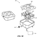
- FIG. 1B is an exploded view of a stimulus pod 110 in accordance with several embodiments of the present disclosure.
- the stimulus pod 110 can include a stimulus surface 150 that contacts patient's skin to deliver heat, mild electrical stimuli, vibration, and/or other stimuli to the patient's body.
- the stimulus pod 110 can also include a battery 155, a circuit board 160, a charging coil 165, and several housing elements 170.
- the battery 155 can power the stimulus surface and the circuit board 160.
- the battery 155 can be a lithium polymer battery or another suitable battery type.
- the charging coil 180 can be configured to receive power from a power source and deliver the power to the battery 155.
- the stimulus pod 110 can include a wireless communication link 175 through which the stimulus pod 110 receives instructions and/or sends data to and from a control station (described in greater detail below).
- the housing elements 170 can include an upper cover 170a and a body 170b that enclose the internal components and provide a convenient handling surface.
- the stimulus pods 110 can include attachment means to attach the stimulus pod 110 to the anchor 120.
- the stimulus pod 110 can have metal slugs 105 that can be magnetized and coupled to a metallic attachment ring 124 in the anchor 120 to hold the stimulus pod 110 to the anchor 120.
- the slugs 105 can also be used for stimulus delivery.
- the metal slugs 105 can be positioned on a top side of the stimulus pods 110 and can be used to interface with a charging station discussed in more detail below.
- FIG. 2 shows an anchor 120 as assembled, and in an exploded view in accordance with several embodiments of the present disclosure.
- the anchor 120 can include an upper surface 130, an attachment ring 124, an adhesive layer 135, and a liner 140.
- the liner 140 can be removed to expose the adhesive layer 135 before placing the anchor 120 on the patient's body.
- the upper surface 130 is exposed to the ambient conditions and accordingly can be similar to a bandage or a wound covering to provide a clean, water-resistant surface for the anchor 120.
- the attachment ring 124 Beneath the upper surface 130, can include a metallic ring such as a steel ring that corresponds to magnets 185 in the stimulus pod 110.
- the ring 124 is held to the upper surface 130 by the adhesive layer 135, which can have an adhesive on the upper side to adhere to the ring 124 and the upper surface 130, and on the lower side to adhere to the liner 140.
- the materials can all be rigid enough to maintain a proper shape, but flexible enough to substantially conform to the patient's body.
- the ring 124 can be segmented or thin to permit the anchor 120 to flex to some degree.
- Figures 3A-3C illustrate several embodiments in accordance with the present disclosure including various attachment means between the anchor 120 and the stimulus pod 110.
- the stimulus from the stimulus pod 110 is best delivered to the patient's body with a stimulus surface 150 directly contacting the patient's skin.
- the anchor can take different forms to keep the stimulus surface 150 against the patient's skin, some of which are shown using the cross-sectional views of Figures 3A-3C.
- Figure 3A shows a stimulus pod 110 having a plug 152a that extends slightly beyond the anchor 120.
- the plug 152a can have a stimulus surface 150a with a flat profile.
- the attachment ring 124 can engage the stimulus pod 110 with sufficient force that the stimulus surface 150a presses down onto the patient's skin to ensure sufficient contact with the skin.
- Figure 3B shows an alternative embodiment including a plug 152b with a stimulus surface 150b that is convex.
- the slope of the convex stimulus surface 152b can depend in part on the application and size of the stimulus pod 110.
- the convex stimulus surface 150b can have more surface area than the flat stimulus surface 150a, provided that the slope is not too extreme such that portions of the stimulus surface 150b do not contact the patient's skin.
- Figure 3C illustrates yet another embodiment including a plug 152c that similarly extends beyond the anchor 120, and has a stimulus surface 150c. In this embodiment, the stimulus surface 150c has several small bumps or projections 240.
- the dimensions of the stimulus surface 150c and the bumps 240 can be chosen to increase the surface area of the stimulus surface 150c that contacts the patient's skin without creating void spaces or air pockets between the bumps 240 that might reduce effective heat transfer or delivery of other stimuli.
- the projections 240 are not discrete, but are continuous and/or sinusoidal.
- Figure 4 illustrates several embodiments of the present disclosure in which the attachment means between the anchor 120a and the stimulus pod 110 include various attaching mechanisms.
- Figure 3A contains several magnified views of a region marked "A" which depicts the interface between the anchor 120a and the stimulus pod 110.
- the anchor 120a contains a metallic or magnetic ring 250 that corresponds to a magnet 185 in the stimulus pod 110. The magnetic force between the ring 250 and the magnets 185 hold the stimulus pod 110 in place relative to the anchor 120a.
- an anchor 120b can be held to the stimulus pod 110 by a mechanical fastener 255 such as a snap, or other similar mechanical attachment means.
- the attachment mechanism can operate along the same principle as a plastic cap on a cardboard cup, such as a coffee cup and lid.
- Either the stimulus pod 110 or the anchor 120b can contain a resilient recession and the other can contain a matching, resilient projection that, when pressed together, mechanically hold the stimulus pod 110 in place on the anchor 120b.
- a hook-and-loop fastener 260 can be used.
- Other embodiments use the interior surface 265 of an anchor 120d and a corresponding, resilient exterior surface 270 of a plug 152d that can be pressed into the aperture 122 of the anchor 120 and snap into place.
- an anchor 120f can include a keyed aperture 122 having an irregular interior surface 265, and a plug 152f of the stimulus pod 110 can include a correspondingly irregular external surface 270 that can be placed over the aperture 122 and rotated slightly with portions of the irregular exterior surface 270 engaging with the anchor 120f to hold the stimulus pod 110 in place.
- any of the attachment mechanisms provide a simple way for a patient to apply a stimulus pod 110 to their body.
- the stimulus pods 110 can be interchangeable between anchors 120, and vice versa.
- a patient can use a stimulus pod 110 until the battery is depleted, and then simply swap in another stimulus pod 110 with a fresh battery.
- the attachment means can be strong enough and the dimensions of the stimulus pod 110 can be small enough that the stimulus pod 110 can be worn under the patient's clothing easily.
- the placement of the anchors 120 can vary greatly according to a predetermined diagnostic pattern or personal preference.
- the stimulus pods 110 can be placed at an area of discomfort, such as a painful lower back.
- a patient may use a stimulus pod 110 at the lower back-where the pain is-but they can also use a secondary stimulus pod 110 near the shoulders or on the legs.
- Multiple stimulus pods 110 can be used in concert to produce an aggregate affect.
- two stimulus pads 110 placed near one another are perceived as a single, large stimulus pad 110.
- the patient's back has much lower nerve density than the face, neck, or arms.
- the patient can use a pair of small stimulus pads 110 (e.g., one or two inches in diameter) at the lower back spaced about three or four inches apart and achieve the same sensory result as a larger stimulus pad covering the entire area.
- An unexpected benefit of this arrangement is that much less power is required to provide the stimulus in two small areas than would be required to stimulate the entire area.
- FIGs 5A and 5B illustrate a charging station 200 according to several embodiments of the present disclosure.
- Figure 5A shows a charging station 200 including several sockets 205 shaped to receive a single stimulus pod 110.
- the charging station 200 includes four sockets 205. Other configurations can have a different number of sockets 205.
- Figure 5B is a partially exploded view of the charging station, which can include a charging coil 210 and a circuit board 215 under each socket 205.
- the charging station 200 can also include an electrical connector 220 that can be plugged into a standard electrical outlet or other power source to provide power to the charging station 200.
- the charging station 200 can detect when a stimulus pod 110 is seated in the socket 205 through a wireless signal, a proximity sensor, or because the pods 110 depress a button in the sockets 205.
- the corresponding circuit board 215 can instruct the charging coil 210 to transmit power to the charging coil 180 of the stimulus pod 110.
- the stimulus pods 110 can have an asymmetric shape that matches a corresponding, negative shape in the sockets 205 to ensure proper alignment with the sockets 205.
- the pods 110 can include a contact point that can be used for charging the pods 110 or as control inputs for the pods 110.
- the stimulus pods 110 can include contacts on a topside (e.g., on the upper cover 170a) through which the pods 110 can exchange electrical power and communication signals when placed on the sockets 205 with the upper cover 170a face-down.
- a topside e.g., on the upper cover 170a
- the pods 110 can exchange electrical power and communication signals when placed on the sockets 205 with the upper cover 170a face-down.
- the charging station 200 can include a light 225 that can indicate that the charging station 200 is transmitting power to a stimulus pod 110.
- the stimulus pod 110 can notify the charging station 200 which can then cease charging the battery 155 and change the light 225 to indicate that the battery 155 is fully charged and is ready for use.
- the charging station 200 can charge the stimulus pods 110 that have less than a full charge while not powering the stimulus pods 110 that have a more full charge.
- FIG. 5C shows a charging station 211 according to several embodiments of the present disclosure.
- the illustrated charging station 211 has two sockets 205 for receiving stimulus pods 110, but a charging station with just one or more than two sockets 205 is also possible.
- the charging station 211 can be plugged into a standard electrical outlet using a cord 212.
- Sockets 205 have socket connectors 214 that mate with pod connectors 209 when a pod is inserted into a socket.
- Sockets 205 can have a notch 213 to accommodate an on/off switch 207 on the stimulus pod 110.
- the notch 213 can also serve as a keying feature to assure proper alignment of the socket connectors with the pod connectors 209.
- Figure 5C further shows the stimulus pods 110 having the pod connectors 209 either on the lower surface of the pod (as shown in the upper view of the stimulus pod 110) or on the upper surface of the pod (as shown in the lower view of the stimulus pod 110).
- the pod connectors 209 on the upper surface of the stimulus pod, because that surface is away from the patient's skin; in consequence, the connector contamination is less likely.
- the stimulus pod 110 can also have on/off switch 207.
- a simple push type on/off switch is illustrated, but many other types of switches are also possible including, for example, a slide switch, an optical switch, touch sensor, etc.
- the on/off switch is typically activated after the contact with the patient's skin has been established, because the patient's skin provides a minimum threshold temperature below which the stimulus pod 110 will not activate, which can also be a safety mechanism preventing an accidental discharging of the stimulus pod.
- the on/off switch 207 can be configured to control a number of heat cycles and/or temperature of the stimulus pod 110.
- the stimulus pod 110 can also have a heat cycle switch 206 to choose heat level like, for example, low, medium or high.
- the corresponding indicators 208A-C can light up in response to a particular heat cycle switch 206 setting. In the alternative, a single indicator 208 capable of changing its color can be used to indicate low, medium or high temperature.
- a push type heat cycle switch 206 is illustrated in Figure 5C , but other types of switch like, for example, slide switch, multi-pole throw switch, touch sensitive switch, etc. are also possible.
- the stimulus pods 110 can communicate with a control station 230, shown schematically in Figure 5B through any accepted wireless or wired protocol, including radio frequency (RF), infrared light, laser light, visible light, acoustic energy, BLUETOOTH, WIFI, or other communication systems.
- RF radio frequency
- the signals can be sent and received through the patient's skin.
- sending and receiving signals through the patient's skin may be particularly well suited for determining a distance between the pods.
- the control station 230 can be a desktop or laptop computer, a smartphone, for example an i-Phone, or other device.
- the control station 230 can be included with the charging station 200, and in some cases can share components such as a power source, circuitry, etc.
- the control station 230 can instruct one or more stimulus pods 110 to apply heat, electric stimuli, vibration, or other stimulus or combination of stimulus in various patterns to the patient's body.
- the pods 110 include a button or series of buttons through which the pods 110 can be manually operated.
- the possible applications are many, and include various combinations of ramp up operations, maximum intensity operations (e.g., maximum temperature or maximum electrical current, etc.), ramp down operations, stimulus soak operations, and lockout period operations.
- the stimulus can be applied from different stimulus pods 110 at different levels and patterns.
- a patient may place a stimulus pod 110 at their upper back, their lower back, and near each of their shoulders or in a different arrangement.
- the control station 230 can vary the stimulus application at the various zones according to a predetermined pattern. If a smartphone or other device having a screen is used as a control station, the screen may display a graphical representation of patient's body with indication as to where to locate the pods 110 in a particular application. Furthermore, the screen may display a countdown time information for all or some pods 110.
- the control station 230 can have information regarding the location of the stimulus pods 110 on the patient's body, and can vary the stimulus pattern accordingly.
- the stimulus pods 110 can be built with certain body positions in mind.
- the stimulus pods 110 can carry body position labels to instruct the patient to apply the stimulus pods 110 according to the label. For example, in a set of four stimulus pods, two can be marked "shoulders," a third can be marked “lower back,” and a fourth can be marked "upper back.”
- the anchors can communicate its location to the stimulus pod 110.
- the anchor 120 can include a passive identifier such as an RFID tag or other simple, passive method of communicating with the stimulus pod 110. In this embodiment, the anchor 120 can remain in place even when different stimulus pods 110 are swapped in and out of the anchor 120.
- the stationary anchor 120 can accurately provide location information to the control station 230 independent of which specific stimulus pod 110 occupies the anchor 120.
- the patient can inform the control station 230 where the stimulus pods 110 are situated, and with this information the control station 230 can apply the desired stimulus pattern to the stimulus pods 110.
- the stimulus pods 110 can fire sequentially, and the patient can indicate the location of the stimulus on a user interface. Through the user interface, the patient can also operate the system 100 and apply treatment.
- a control station 230 that comprises a smart phone or a computer, a graphic depiction of the patient's body can be shown and the patient can indicate to the control station 230 where the stimulus pods 110 are located.
- the patient can directly control the stimulus application through the stimulus pods 110 by moving a pointing device along the graphical depiction of their body to create a virtual stimulus-massage that the patient, or a healthcare professional, controls directly.
- the control station 230 can include a touch screen that the patient can touch to apply heat or other stimulus to various portions of their body (or to the body of another patient).
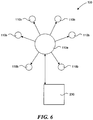
- Figure 6 depicts further embodiments of a stimulus delivery system 100 according to the present disclosure.
- the stimulus delivery system 100 includes a control station 230, at least one index pod 110a, and several dummy pods 110b.
- the relationship between the index pod 110a and the dummy pods 110b can be similar to a master/drone relationship.
- the index pod 110a can include more sophisticated telemetry equipment than the dummy pods 110b, and can act as an intermediary between the dummy pods 110b and the control station 230.
- the index pod 110a may include stimulus components, such as a heating surface or vibration equipment, and can deliver stimulus just like a dummy pod 110b.
- the index pod 110a can be a dedicated index pod 110a with communication equipment, but without stimulus equipment.
- the index pod 110a and control station 230 can discern when two or more stimulus pods 110 (e.g., dummy pods 110b or index pods 110a) are near enough to one another that they can work in aggregate. If the control station 230 knows where the stimulus pods 110 are placed on the patient's body, the control station 230, through the index pods 110a, can vary the threshold distance between stimulus pods 110a, 110b as a function of nerve density at different locations on the body.
- two or more stimulus pods 110 e.g., dummy pods 110b or index pods 110a
- the control station 230 can operate the stimulus pods 110a, 110b together to effectively cover the area between the stimulus pods 110a, 110b as well as the area directly contacting the stimulus pods 110a, 110b.
- the control station 230 can determine that the aggregate effect may not be perceived to reach the area between the stimulus pods 110a, 110b because of the greater nerve density. This information can be used when applying a treatment plan that calls for stimulus on a prescribed area.
- the control station can determine whether there is a stimulus pod 110 on or near the prescribed area, and if not, whether the aggregate effect from two or more stimulus pods 110 can be used to carry out the treatment plan, and can execute the plan through the pods 110.
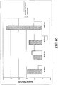
- Figures 7A-D show the results of a study that was designed to understand how to optimize heat levels, intermittency and heat distribution to produce more effective analgesia (pain relief).
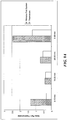
- Figures 8A-C show comparison results between a ThermaCare heater and the stimulus pod system as in this invention treating the pre-menstrual syndrom.
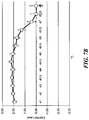
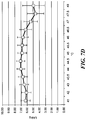
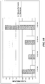
- Figures 9A-C show comparison results between the ThermaCare heater and the stimulus pod system as in this invention when treating lower back pain.
- a stimulus pod system for the clinical study was designed and built to optimize heat levels, intermittency and distribution.
- the stimulus pod system included a software controller, a set of instructions on a laptop computer and a hardware interface that connected a variety of stimulus pods to the laptop controller.
- controllers and interfaces could be used for the modular stimulus applicator system including, for example, off-shelf dedicated controllers and a software based controller on a smart phone or a tablet computer connected through a wireless or wired interfaces to the stimulus pod system.
- the software controller was used to control thermal variables. These variables include:
- the control laptop was connected via a USB port to a heating interface unit. This interface allowed controlling one to four stimulus pods.
- the pods had electrical resistance pads with embedded thermistors, which allowed for very tight control of temperature.
- the study initially utilized three sizes of stimulus pods: small (0.5 x 0.5 inches), medium (1 x 1 inches) and large (1.5 x 1.5 inches).
- the stimulus pods were connected to the heating interface unit with 8 ft long cables that allowed test subjects to move about the testing station.
- the protocol was initially tested on 10 in-house subjects. Afterwards, a total of 23 outside subjects completed the entire initial protocol which was done in one 90 minute session. The results of the in-house testing were similar to the formal trial results. Within the group of 23 test subjects, 14 were females (61%) and 9 males (39%) with a mean age of 31 years (range 17-59, standard deviation ⁇ 9.9 years). The subjects were given explanation about the study procedure and study device. In an initial subset of subjects, each subject tried three different sizes of stimulus pods (small, medium, large) to determine what size was preferred for the subsequent phases of the study. The midsize stimulus pod was strongly preferred, and was used for the subsequent studies. In some instances, the subjects could not determine if the smallest pad was even heating. Also, there was no preference among the subjects for heating a larger area of the body by using a larger size (1.5x1.5 inches) stimulus pods.
- the subject was fitted with a variety of stimulus pods, and locations and the preferences were recorded. It was observed that the subjects were able to detect a difference in heat pulses of less than 1 ° C. As explained in more detail below, the subjects preferred a temperature that was significantly warmer (44.7 ° C) than the 40 ° C provided by ThermaCare.
- the initial testing was done to determine the preferred temperature of the stimulus pods.
- the heating started at 41° C for two minutes duration and then gradually increased in the 0.5° C increments up to either a maximum temperature of 50° C or until the subject felt that the pads were too hot.
- the initial ramp-up was also varied and evaluated for the subject preference.
- Figure 7A shows that the preferred heating pad temperature was 44.6° C (range 42-48° C, standard deviation ⁇ 1.4° C). Only a few subjects preferred a temperature greater than 46 degrees.
- subjects indicated that the perceived comfort of the heating pads gradually increased with the temperature up to approximately 45.5° C. Thereafter, the perceived comfort declined for most subjects.
- the comfort level can range from 3, which signifies "very comfortable,” to -3, which signifies "very uncomfortable.”
- the vertical bars on the plot symbols indicate confidence interval in all graphs.
- the temperature preferences and ratings were quantified using a thermal sensation scale that progressed from “very cold,” “cold,” “slightly cool,” “neutral,” “slightly warm,” “warm,” “hot,” to “very hot.”
- the thermal sensation is scales from 0 (temperature neutral) to 6 (very hot).
- the temperature was rated as a "hot” or "very hot.”
- the subjects indicated a gradual increase in "liking” of the temperature until about 46° C.
- the “liking” was on the scale of 0 (terrible) to 10 (wonderful).
- the temperature range from about 44° C to about 46° C was the closest to "wonderful.” Outside of the 44° C to 46° C range, the temperature "liking" was falling away from “wonderful.”
- this study systematically evaluated properties of heat that are likely to relate to thermal analgesia.
- the subjects preferred temperatures that were significantly hotter than the 40 ° C, which can be provided by chemical heat packs such as, for example, ThermaCare.
- the actual or optimal temperature preferred by the subjects varied and approached a a bell shaped distribution.
- the small size heating pods 0.5 x 0.5 inches
- the larg size heating pods 1.5 x 1.5 inches
- the medium size pads were the most preferred. It is possible that the small pads were too small to optimally stimulate the cutaneous thermal receptive fields. In many instances when subjects were asked how large of an area was being stimulated both the medium and large pods produced a heated area that was similar in size.
- FIGS 8A-C illustrate the results of clinical studies of the stimulus pod system as applied for the treatment of PMS and dysmenorrhea (menstrual cramps felt during menstrual periods).
- PMS affects a large percentage of women - more than 50 percent of all women who have a menstrual period. About 20% to 40% of women experience symptoms that make life difficult. Approximately 5 to 15 percent of these women have severe pain that interferes with daily activities. Additionally, 2.5% to 5% experience PMS that is debilitating. Heat is a well recognized self treatment technique used to help relieve the cramps and the pains (back, abdominal and pelvic) associated with PMS. In spite of both empiric evidence and formal studies little is known about mechanisms or heat doses that are effective for PMS relief. Recent studies demonstrate that low level heat can significantly reduce PMS pain, and can even reduce the amount of pain medications used to treat PMS.
- the study compared analgesic effects of the stimulus pod system as in this invention with those of a commercially available ThermaCare® wrap.
- the stimulus pod system consisted of two heating pads that can be set to a temperature selected by the individual subject. The temperature range of the heater could be set between and including 42 to 47° C.
- the ThermaCare wrap is a commercial product available over the counter. The ThermaCare wrap is attached to the skin using its own elastic wrap. ThermaCare heats at a steady 40° C.
- RA research assistant
- the RA explained and demonstrated the heating devices operation, their purpose and the methods of the study.
- the subjects were randomly assigned to one of two groups: the stimulus pod system or the ThermaCare group. All subjects completed a brief questionnaire about their pain.
- the study flow is illustrated in Figure 8A .
- the RA facilitated a run-in period in which the subjects were able to gradually increase the temperature of the heating pads starting at 42° C up to a maximum of 47° C.
- the subjects wore the stimulus pod system and provided pain assessments at baseline and after 10 minutes, 20 minutes and 30 minutes. After completing the study subjects filled out an exit interview questionnaire and were paid for their participation.
- Figure 8B shows the results of the Iowa Pain Thermometer measurements for the stimulus pod system and ThermaCare. The results indicate significantly greater decrease in Iowa Pain Thermometer scores from baseline to 30 minutes when participants used the stimulus pod system device in comparison with ThermaCare use. Similar differences were found from the baseline to 10 minutes, and from the 20 to 30 minute assessment. No significant differences were found in the reduction of Iowa Pain Thermometer scores in the 10 to 20 minutes assessment.
- Figure 8C shows the results of the Numeric Rating Scale. The reduction in NRC from baseline to 30 minutes was greater when using the stimulus pod system. The subjects that used the stimulus pod system device also reported greater reduction of pain on the Numeric Rating Scale from baseline to 10 minutes, and from 20 to 30 minutes. Similarly to the Iowa Pain Thermometer scores, no significant differences were found for the two devices in the pain reductino from 10 to 20 minutes.
- Figures 9A-C illustrate the results of the lower back pain study.
- One third of all Americans suffer from back pain at some point during a given year.
- the estimated number of individuals in the United States that suffer from chronic pain varies from 160 million on down, but is generally cited as being close to 50 million.
- the lower back pain costs employers more than $60 billion a year in lost productivity. If the cost of treatment is added to that number, then the cost is estimated at about $100 billion a year.
- Men and women are equally affected by the back pain.
- the pain occurs most often to people between ages 30 and 50, due in part to the aging process, but also as a result of sedentary life styles with too little (sometimes punctuated by too much) exercise.
- the risk of experiencing low back pain from disc disease or spinal degeneration also increases with age.
- Back pain is the second most common neurological ailment in the United States - only headache is more common.
- Figure 9B shows that the reduction of pain rating on the Numeric Rating Scale from baseline to 30 minutes was also greater when using the stimulus pod system device. Similar to the Iowa Pain Thermometer scores, the subjects using the stimulus pod system also reported greater reduction of pain on the Numeric Rating Scale from baseline to 10 minutes, and from 20 to 30 minutes. No significant differences in the reduction of pain were found from 10 to 20 minutes.
- both treatments produced reduction in pain in the subjects who suffered from chronic low back pain.
- the stimulus pod system produced significantly higher pain relief in comparison to ThermaCare.
- the higher heat provided by the stimulus pod system was associated with better and more profound pain relief.
- subjects almost unanimously noted that they all preferred the warmer temperatures from the stimulus pod system than that offered by the low level heat of the ThermaCare product.
- Many subjects also stated that they very much liked the pulsing sensation provided by the Heater device.
Claims (9)
- Système (100) permettant de traiter des portions du corps d'un patient, comprenant :un module de stimulation rechargeable (110) incluant une surface de contact (150) configuré pour entrer en contact avec le corps du patient, une batterie (155), et une carte à circuit (215) contenant une logique de commande pour le module de stimulation (110) ;un ancrage (120) ayant une surface adhésive (135) configurée pour s'appliquer au corps du patient,une ouverture (122) configurée pour recevoir la surface de contact (150) du module de stimulation (110) avec la surface de contact (150) saillant à travers l'ouverture (122) au-delà de la surface adhésive (135) de l'ancrage (120) et contre le corps du patient ; etun dispositif d'accouplement (124) configuré pour assujettir le module de stimulation (110) à l'ancrage (120) avec la surface de contact (150) du module de stimulation (110) en contact avec le corps du patient, dans lequel le module de stimulation (110) est assujetti de façon amovible à l'ancrage (120), et dans lequel le module de stimulation (110) est configuré pour apporter la stimulation au corps du patient selon la logique de commande telle qu'instruite par la carte à circuit (215).
- Système (100) selon la revendication 1, dans lequel le module de stimulation (110) est configuré pour traiter le corps du patient avec soit une stimulation thermique, soit une stimulation électrique, soit une stimulation vibratoire, ou dans lequel le dispositif d'accouplement (124) comprend soit une liaison magnétique, soit une fixation mécanique élastique, soit une fixation à crochet et boucle, soit une fixation filetée et dans lequel la surface de contact (150) du module de stimulation (110) a soit un profil plat (150a), soit un profil convexe (150b), soit une série de saillies (240), soit un profil sinusoïdal.
- Système (100) selon la revendication 1, dans lequel le dispositif d'accouplement (124) comprend une paire de saillies/renfoncements mécaniques élastiques configurés pour s'engager lorsqu'ils sont pressés ensemble.
- Système (100) selon la revendication 1, dans lequel le dispositif d'accouplement (124) comprend une fixation à crochet et boucle (260).
- Système (100) selon la revendication 1, dans lequel le dispositif d'accouplement (124) comprend une fixation filetée.
- Système (100) selon la revendication 1, dans lequel le dispositif d'accouplement (124) comprend des lingots métalliques aimantés (105) configurés pour :s'accoupler à une bague de fixation métallique (250) dans l'ancrage (120) pour maintenir le module de stimulation (110a) avec l'ancrage (120), etapporter une stimulation au corps du patient.
- Système (100) selon la revendication 1, dans lequel le dispositif d'accouplement (124) comprend un aimant (185) dans le module de stimulation (110) et une bague magnétique correspondante (250) à l'ancrage (120), la bague magnétique (250) étant configurée pour s'engager magnétiquement avec l'aimant (185).
- Système (100) selon la revendication 2, dans lequel les saillies (240) à la surface de contact (150) du module de stimulation (110a) sont séparées les unes des autres.
- Système (100) selon la revendication 1, dans lequel la totalité de la surface de contact (150) du module de stimulation (110a) est en saillie au-delà de la surface adhésive (135) de l'ancrage (120).
Priority Applications (1)
| Application Number | Priority Date | Filing Date | Title |
|---|---|---|---|
| PL12736967T PL2665457T3 (pl) | 2011-01-21 | 2012-01-23 | System modułowego aplikatora bodźców |
Applications Claiming Priority (2)
| Application Number | Priority Date | Filing Date | Title |
|---|---|---|---|
| US201161435221P | 2011-01-21 | 2011-01-21 | |
| PCT/US2012/022252 WO2012100258A2 (fr) | 2011-01-21 | 2012-01-23 | Système et procédé d'application de stimulation par modules |
Publications (3)
| Publication Number | Publication Date |
|---|---|
| EP2665457A2 EP2665457A2 (fr) | 2013-11-27 |
| EP2665457A4 EP2665457A4 (fr) | 2014-09-17 |
| EP2665457B1 true EP2665457B1 (fr) | 2019-06-12 |
Family
ID=46516436
Family Applications (1)
| Application Number | Title | Priority Date | Filing Date |
|---|---|---|---|
| EP12736967.6A Active EP2665457B1 (fr) | 2011-01-21 | 2012-01-23 | Système d'application de stimulation par modules |
Country Status (8)
| Country | Link |
|---|---|
| US (2) | US10603208B2 (fr) |
| EP (1) | EP2665457B1 (fr) |
| JP (3) | JP6502612B2 (fr) |
| KR (1) | KR101949543B1 (fr) |
| CA (1) | CA2860977C (fr) |
| ES (1) | ES2744701T3 (fr) |
| PL (1) | PL2665457T3 (fr) |
| WO (1) | WO2012100258A2 (fr) |
Families Citing this family (30)
| Publication number | Priority date | Publication date | Assignee | Title |
|---|---|---|---|---|
| US8579953B1 (en) | 2007-12-07 | 2013-11-12 | Peter J. Dunbar | Devices and methods for therapeutic heat treatment |
| WO2013059658A1 (fr) | 2011-10-19 | 2013-04-25 | Sympara Medical Inc. | Méthodes et dispositifs pour le traitement de l'hypertension |
| DE102012004215A1 (de) * | 2012-03-06 | 2013-09-12 | Jochen Welte | Reizstromgerät |
| US9962546B2 (en) * | 2013-02-21 | 2018-05-08 | Meagan Medical, Inc. | Cutaneous field stimulation with disposable and rechargeable components |
| CN104033537A (zh) * | 2013-03-08 | 2014-09-10 | 苏州凯得瑞液压机械有限公司 | 一种连接动力机和钟型罩的减振环 |
| EP2815787A3 (fr) * | 2013-04-30 | 2015-04-08 | Bomedus GmbH | Agencement d'électrodes et appareil de traitement de douleurs |
| DE102013011712B4 (de) * | 2013-07-15 | 2015-08-27 | Christopher Berndt | Bandage für Epicondylitis mit Fernsteuerung |
| CN103394162B (zh) * | 2013-08-20 | 2015-08-19 | 广州龙之杰科技有限公司 | 一种基于无线方式的磁振热治疗仪及其实现方法 |
| WO2015028480A1 (fr) | 2013-08-28 | 2015-03-05 | Koninklijke Philips N.V. | Système de stimulation de soulagement de la douleur |
| CN106456357A (zh) * | 2014-03-03 | 2017-02-22 | 物理治疗有限公司 | 刺激系统、设备及其使用方法 |
| CA2946814A1 (fr) | 2014-04-28 | 2015-11-12 | King Abdullah University Of Science And Technology | Timbre thermique a puce pour une thermotherapie adaptative |
| US9999363B2 (en) * | 2015-04-13 | 2018-06-19 | Lawrence Livermore National Security, Llc | System and method for neural interface with modular active electronics |
| CN107645946A (zh) * | 2015-10-13 | 2018-01-30 | 伊曼·沙菲路 | 智能关节护理 |
| NO20151454A1 (en) * | 2015-10-27 | 2017-04-28 | Unikia AS | Device for relieving back pain. |
| USD802779S1 (en) | 2015-12-28 | 2017-11-14 | Omron Healthcare Co., Ltd. | Nerve stimulator |
| US10149975B2 (en) | 2016-03-01 | 2018-12-11 | Easywell Biomedicals, Inc. | Transcutaneous electrical nerve stimulation device |
| US20180303704A1 (en) | 2016-04-08 | 2018-10-25 | Vibrating Therapeutic Apparel, Llc | Vibrating therapeutic apparel |
| KR101939810B1 (ko) | 2017-07-14 | 2019-01-18 | 재단법인 아산사회복지재단 | 온도 제공장치 |
| JP2019037451A (ja) * | 2017-08-24 | 2019-03-14 | パナソニックIpマネジメント株式会社 | 美容器具 |
| US20190110949A1 (en) * | 2017-10-18 | 2019-04-18 | Raja Bhatti | Hand-attached controlled pulsed vibration device |
| US10695262B2 (en) * | 2017-12-05 | 2020-06-30 | Brownmed, Inc. | Flexible vibration module for snap in attachment to a grommet embedded in a compression wrap |
| EP3761925A4 (fr) * | 2018-03-07 | 2021-12-08 | Soovu Labs, Inc. | Systèmes et méthodes permettant un soulagement amélioré de la douleur émanant de la stimulation de fibres thermiques |
| EP3578146A1 (fr) * | 2018-06-07 | 2019-12-11 | Dermapharm AG | Dispositif mobile de traitement de démangeaisons pourvu d'interface |
| US20200016305A1 (en) * | 2018-07-10 | 2020-01-16 | Eran Weinberg | Device for Stimulating Milk Flow |
| US20220085628A1 (en) * | 2018-12-27 | 2022-03-17 | Soovu Labs, Inc. | Electrical isolation during battery charging of wearable devices |
| CN110638638B (zh) * | 2019-10-23 | 2021-09-17 | 陈亚蓓 | 一种骨科用手、腿部疗养环流式艾灸装置 |
| US20220062091A1 (en) * | 2020-08-25 | 2022-03-03 | Raganpreet Kaur Rai | Versatile handheld massaging system |
| KR102412807B1 (ko) | 2020-10-08 | 2022-06-24 | 주식회사 루토닉스 | 이온토포레시스 기반의 패치형 피부 관리기 |
| CN112515954B (zh) * | 2020-12-18 | 2022-04-29 | 成都天府新区人民医院 | 一种中医皮肤科薰药工具 |
| USD1023326S1 (en) * | 2021-10-29 | 2024-04-16 | Hyperice Ip Subco, Llc | Combined module and pad |
Family Cites Families (89)
| Publication number | Priority date | Publication date | Assignee | Title |
|---|---|---|---|---|
| US1377158A (en) | 1919-10-29 | 1921-05-03 | Stearinerie Et Savonnerie De L | Process for producing catalytic agents for reduction or hydrogenation purposes |
| JPS508944Y1 (fr) * | 1970-07-20 | 1975-03-18 | ||
| US3857397A (en) | 1972-11-27 | 1974-12-31 | Custom Materials Inc | Electrically conductive wrist strap |
| US4107509A (en) | 1977-03-07 | 1978-08-15 | Northern Electric Company | Apparatus for treating body members with heat and moisture |
| CA1089904A (fr) | 1978-02-03 | 1980-11-18 | Joseph M. Bender | Coussin chauffant par rayonnement |
| US4201218A (en) | 1978-12-22 | 1980-05-06 | Berman Philip G | Therapeutic heat application |
| US4245149A (en) | 1979-04-10 | 1981-01-13 | Fairlie Ian F | Heating system for chairs |
| US4310745A (en) | 1979-04-20 | 1982-01-12 | Huebner Bros. Of Canada Ltd. | Heating assemblies |
| FR2456453A1 (fr) | 1979-05-10 | 1980-12-05 | Sunbeam Corp | Element chauffant flexible et son procede de fabrication |
| US4398535A (en) | 1979-11-27 | 1983-08-16 | Sunset Ltd. | Hyperthermia technique |
| US4279255A (en) | 1980-02-26 | 1981-07-21 | John F. Taylor | Localized body heat applicator device |
| US4396011A (en) | 1981-01-09 | 1983-08-02 | Clairol Incorporated | Heating pad |
| AT383931B (de) | 1982-11-11 | 1987-09-10 | Hans Oppitz | Flaechenheizelement, insbesondere fuer verbaende oder heizdecken |
| US4575097A (en) | 1984-06-01 | 1986-03-11 | Fastencold, Inc. | Therapeutic device and method for forming and using same |
| US4736088A (en) | 1985-07-18 | 1988-04-05 | Battle Creek Equipment Company | Therapeutic heating pad and muff structure |
| JPS6244255A (ja) * | 1985-08-22 | 1987-02-26 | 有限会社 協栄メツキ工業所 | 充電式の温灸器 |
| WO1987002891A1 (fr) | 1985-11-07 | 1987-05-21 | Pfizer Inc. | Composes et procede de traitement local des inflammations et des douleurs |
| WO1989006931A1 (fr) | 1988-02-03 | 1989-08-10 | Stihler Electronic Medizintechnische Geräte Produk | Systeme de chauffage pour tables d'operation |
| US4930317A (en) | 1988-05-20 | 1990-06-05 | Temperature Research Corporation | Apparatus for localized heat and cold therapy |
| US5097828A (en) | 1990-09-25 | 1992-03-24 | Richard Deutsch | Thermoelectric therapy device |
| JP2617839B2 (ja) * | 1991-07-02 | 1997-06-04 | 株式会社アドバンス | 電気温熱治療器 |
| JPH0576435U (ja) * | 1991-12-02 | 1993-10-19 | 田中 三郎 | 温灸器の加熱部分 |
| JPH05161691A (ja) * | 1991-12-11 | 1993-06-29 | Toshiba Corp | 温灸器 |
| US5451747A (en) | 1992-03-03 | 1995-09-19 | Sunbeam Corporation | Flexible self-regulating heating pad combination and associated method |
| US5954680A (en) | 1992-06-19 | 1999-09-21 | Augustine Medical, Inc. | Near hyperthermic heater wound covering |
| US5947914A (en) | 1995-02-21 | 1999-09-07 | Augustine Medical, Inc. | Wound covering |
| US6406448B1 (en) | 1992-06-19 | 2002-06-18 | Augustine Medical, Inc. | Normothermic heater covering for tissue treatment |
| US5986163A (en) | 1992-06-19 | 1999-11-16 | Augustine Medical, Inc. | Normothermic heater wound covering |
| US5964723A (en) | 1992-06-19 | 1999-10-12 | Augustine Medical, Inc. | Normothermic tissue heating wound covering |
| US5336255A (en) | 1993-01-11 | 1994-08-09 | Kanare Donald M | Electrical stimulation heat/cool pack |
| US5423874A (en) * | 1994-03-24 | 1995-06-13 | D'alerta; Mario | Patch for applying pain reducing electrical energy to the body |
| US5447530A (en) | 1994-03-28 | 1995-09-05 | Guibert; Raul | Periodic pulsed heat technique for inducing analgesic effects |
| US6110197A (en) | 1994-11-21 | 2000-08-29 | Augustine Medical, Inc. | Flexible non-contact wound treatment device with a single joint |
| US5817145A (en) | 1994-11-21 | 1998-10-06 | Augustine Medical, Inc. | Wound treatment device |
| US6093160A (en) | 1994-11-21 | 2000-07-25 | Augustine Medical, Inc. | Flexible non-contact wound treatment device |
| ES2200066T3 (es) | 1995-06-29 | 2004-03-01 | THE PROCTER & GAMBLE COMPANY | Faja de espalda elastica que tiene elementos termicos en forma de rombo y medios antideslizamiento. |
| US5658583A (en) | 1995-07-28 | 1997-08-19 | Zhang; Jie | Apparatus and methods for improved noninvasive dermal administration of pharmaceuticals |
| US5601618A (en) | 1996-02-26 | 1997-02-11 | James; Brian C. | Stimulation and heating device |
| US5984995A (en) | 1996-03-29 | 1999-11-16 | The Procter & Gamble Company | Heat cells |
| US5674270A (en) | 1996-06-27 | 1997-10-07 | The Procter & Gamble Company | Thermal pad having a common attachment and oxygen permeable side |
| SE518882C2 (sv) | 1996-07-19 | 2002-12-03 | Farzam Nazerian | Anordning för värmebehandling av en kroppsdel, innefattande separata värmeceller och medel för värmelagring |
| US5893991A (en) | 1996-09-24 | 1999-04-13 | Newell; Bertha L. | Battery operated heating system for a vest or a jacket |
| US5735889A (en) | 1996-11-08 | 1998-04-07 | The Procter & Gamble Company | Thermal neck wrap having means for position maintenance |
| US5925072A (en) | 1996-12-31 | 1999-07-20 | The Procter & Gamble Company | Disposable elastic thermal back wrap |
| US6020040A (en) | 1996-12-31 | 2000-02-01 | The Procter & Gamble Company | Thermal pack having a plurality of individual heat cells |
| US6096067A (en) | 1996-12-31 | 2000-08-01 | The Procter & Gamble Company | Disposable thermal body pad |
| US5860945A (en) | 1996-12-31 | 1999-01-19 | The Procter & Gamble Company | Disposable elastic thermal knee wrap |
| AT407480B (de) | 1997-05-06 | 2001-03-26 | Macher David | Heizeinrichtung zum erwärmen einer hautoberfläche bzw. teilbereiche eines menschlichen körpers |
| US5891189A (en) | 1997-08-07 | 1999-04-06 | Payne, Jr.; Joe R. | Heating band device |
| US5906637A (en) | 1997-08-21 | 1999-05-25 | The Procter & Gamble Company | Disposable elastic thermal uniaxial joint wrap |
| US6071304A (en) | 1998-04-06 | 2000-06-06 | Augustine Medical, Inc. | Wound treatment apparatus with a heater adhesively joined to a bandage |
| US6095992A (en) | 1998-04-06 | 2000-08-01 | Augustine Medical, Inc. | Wound treatment apparatus for normothermic treatment of wounds |
| US6955819B2 (en) | 1998-09-29 | 2005-10-18 | Zars, Inc. | Methods and apparatus for using controlled heat to regulate transdermal and controlled release delivery of fentanyl, other analgesics, and other medical substances |
| US6572871B1 (en) | 1999-01-06 | 2003-06-03 | W. Edward Church | Pain treatment method and apparatus using heating wrap and analgesic cream |
| US20040073258A1 (en) | 1999-01-06 | 2004-04-15 | Church W. Edward | Body tissue and skin treatment method using pulsing heating pad and topical cream |
| US6925317B1 (en) * | 1999-06-11 | 2005-08-02 | Spectrx, Inc. | Integrated alignment devices, system, and methods for efficient fluid extraction, substance delivery and other applications |
| AU6076200A (en) | 1999-07-08 | 2001-01-30 | Johnson & Johnson Consumer Companies, Inc. | Exothermic bandage |
| EP1132028B1 (fr) | 1999-09-22 | 2007-08-15 | Matsushita Electric Industrial Co., Ltd. | Element chauffant plan |
| US6567696B2 (en) | 2001-02-06 | 2003-05-20 | Mediseb Ltd. | Physiotherapeutic device |
| US6228103B1 (en) * | 2000-01-19 | 2001-05-08 | Woodside Biomedical, Inc. | Automatically modulating acupressure device |
| US6840955B2 (en) | 2000-01-27 | 2005-01-11 | Robert J. Ein | Therapeutic apparatus |
| AU2001249233A1 (en) * | 2000-03-22 | 2001-10-03 | Advanced Circulatory Systems, Inc. | CPR mask with compression timing metronome and methods |
| US6605012B2 (en) | 2001-03-08 | 2003-08-12 | Philip Muller | Modular broadhead |
| US6353211B1 (en) | 2001-04-09 | 2002-03-05 | Ching-Song Chen | Electric heating device |
| JP3616750B2 (ja) * | 2001-04-11 | 2005-02-02 | 株式会社ジェットスリム | 痩身具 |
| WO2002087700A1 (fr) | 2001-04-26 | 2002-11-07 | The Procter & Gamble Company | Methode, necessaire et dispositif de traitement cosmetique d'etats cutanes |
| US6932155B2 (en) | 2001-10-24 | 2005-08-23 | Shell Oil Company | In situ thermal processing of a hydrocarbon containing formation via backproducing through a heater well |
| US20040098065A1 (en) * | 2002-11-19 | 2004-05-20 | Alliance Health Products, Llc | Transcutaneous nerve and muscle stimulator and method of using the same |
| US6893453B2 (en) | 2002-12-17 | 2005-05-17 | Kimberly-Clark Worldwide, Inc. | Thermal therapy pad with variable heat control |
| CA2518105A1 (fr) * | 2003-03-06 | 2004-09-23 | Afferent Corporation | Procede et appareil pour ameliorer l'equilibre et la demarche de l'humain et prevenir des blessures au pied |
| US6866776B2 (en) * | 2003-03-14 | 2005-03-15 | Wendy Zeller Leason | Heater for massage nodes and massage therapy device including same |
| US7022093B2 (en) | 2003-10-06 | 2006-04-04 | Thermodesigns, Inc. | Self-contained heating and cooling orthopaedic brace |
| ATE520440T1 (de) * | 2004-02-12 | 2011-09-15 | Ndi Medical Llc | Tragbare anordnungen und systeme für die funktionale oder therapeutische neuromuskuläre stimulation |
| WO2005110299A2 (fr) * | 2004-05-07 | 2005-11-24 | Ardica Technologies, Inc. | Procede de regulation de la temperature du corps avec un dispositif électrochimique tout en fournissant une alimentation a la demande a un dispositif electrique |
| US7783361B2 (en) | 2004-09-03 | 2010-08-24 | Ct Investments Ltd. | Radiant therapeutic heater |
| US7871427B2 (en) * | 2005-02-08 | 2011-01-18 | Carewave, Inc. | Apparatus and method for using a portable thermal device to reduce accommodation of nerve receptors |
| JP4731936B2 (ja) * | 2005-02-09 | 2011-07-27 | 本田技研工業株式会社 | 回転式可変抵抗器 |
| US7182739B2 (en) * | 2005-05-12 | 2007-02-27 | S.C. Johnson & Son, Inc. | Therapy patch |
| WO2007092543A2 (fr) * | 2006-02-06 | 2007-08-16 | The Board Of Trustees Of The Leland Stanford Junior University | Moniteur cardiaque non invasif et procédés d'utilisation de données cardiaques enregistrées en continu |
| WO2007136726A2 (fr) * | 2006-05-18 | 2007-11-29 | Ndi Medical, Llc | Ensembles portables, systèmes et procédés permettant de fournir une neurostimulation fonctionnelle ou thérapeutique |
| US7797046B2 (en) * | 2006-10-11 | 2010-09-14 | Cardiac Pacemakers, Inc. | Percutaneous neurostimulator for modulating cardiovascular function |
| US8062343B2 (en) * | 2006-10-13 | 2011-11-22 | Augustine Temperature Management LLC | Heating blanket |
| US8214007B2 (en) | 2006-11-01 | 2012-07-03 | Welch Allyn, Inc. | Body worn physiological sensor device having a disposable electrode module |
| US8060175B2 (en) * | 2007-06-15 | 2011-11-15 | General Electric Company | System and apparatus for collecting physiological signals from a plurality of electrodes |
| US8579953B1 (en) * | 2007-12-07 | 2013-11-12 | Peter J. Dunbar | Devices and methods for therapeutic heat treatment |
| ITPI20080032A1 (it) * | 2008-04-18 | 2009-10-19 | Antonio Mazzeo | Dispositivo di supporto di sensori e/o attuatori facenti parte di una rete di nodi di misura e/o attuazione |
| JP5676445B2 (ja) | 2008-08-01 | 2015-02-25 | エヌディーアイ メディカル, エルエルシー | 機能的または治療的な神経刺激を提供する携帯型アセンブリ、システムおよび方法 |
| KR100915320B1 (ko) | 2008-09-29 | 2009-09-03 | (주)메디룬 | 생리통완화를 위한 휴대용 조합자극기 |
| EP3387991B1 (fr) * | 2010-05-12 | 2022-06-15 | Irhythm Technologies, Inc. | Caractéristiques de dispositif et éléments de construction pour adhérence à long terme |
-
2012
- 2012-01-23 JP JP2013550659A patent/JP6502612B2/ja active Active
- 2012-01-23 CA CA2860977A patent/CA2860977C/fr active Active
- 2012-01-23 US US13/981,081 patent/US10603208B2/en active Active
- 2012-01-23 EP EP12736967.6A patent/EP2665457B1/fr active Active
- 2012-01-23 ES ES12736967T patent/ES2744701T3/es active Active
- 2012-01-23 WO PCT/US2012/022252 patent/WO2012100258A2/fr active Application Filing
- 2012-01-23 KR KR1020137021954A patent/KR101949543B1/ko active IP Right Grant
- 2012-01-23 PL PL12736967T patent/PL2665457T3/pl unknown
-
2018
- 2018-11-12 JP JP2018212186A patent/JP6923501B2/ja active Active
-
2020
- 2020-02-27 US US16/802,775 patent/US20200345537A1/en active Pending
- 2020-04-07 JP JP2020069050A patent/JP2020110662A/ja active Pending
Non-Patent Citations (1)
| Title |
|---|
| None * |
Also Published As
| Publication number | Publication date |
|---|---|
| JP2019034212A (ja) | 2019-03-07 |
| WO2012100258A3 (fr) | 2012-10-18 |
| US10603208B2 (en) | 2020-03-31 |
| WO2012100258A2 (fr) | 2012-07-26 |
| ES2744701T3 (es) | 2020-02-26 |
| US20200345537A1 (en) | 2020-11-05 |
| PL2665457T3 (pl) | 2019-12-31 |
| JP2020110662A (ja) | 2020-07-27 |
| JP6923501B2 (ja) | 2021-08-18 |
| KR101949543B1 (ko) | 2019-02-18 |
| US20140207219A1 (en) | 2014-07-24 |
| JP2014506810A (ja) | 2014-03-20 |
| EP2665457A4 (fr) | 2014-09-17 |
| CA2860977A1 (fr) | 2012-07-26 |
| KR20140042786A (ko) | 2014-04-07 |
| CA2860977C (fr) | 2022-01-11 |
| EP2665457A2 (fr) | 2013-11-27 |
| JP6502612B2 (ja) | 2019-04-17 |
Similar Documents
| Publication | Publication Date | Title |
|---|---|---|
| US20200345537A1 (en) | Modular stimulus applicator system and method | |
| US11628300B2 (en) | Method and apparatus for transdermal stimulation over the palmar and plantar surfaces | |
| CA2751527C (fr) | Systemes et procedes de stimulation musculaire electrique a l'aide d'un champ de guidage d'energie | |
| US9002458B2 (en) | Transdermal electrical stimulation devices for modifying or inducing cognitive state | |
| US20220085628A1 (en) | Electrical isolation during battery charging of wearable devices | |
| JP2020022771A (ja) | 失禁を治療するための装置 | |
| KR20210008328A (ko) | 열 섬유의 자극을 통한 통증 완화 개선을 위한 시스템 및 방법 | |
| CN212973222U (zh) | 加热装置 | |
| US20230218432A1 (en) | Systems and methods for thermal fiber stimulation |
Legal Events
| Date | Code | Title | Description |
|---|---|---|---|
| PUAI | Public reference made under article 153(3) epc to a published international application that has entered the european phase |
Free format text: ORIGINAL CODE: 0009012 |
|
| 17P | Request for examination filed |
Effective date: 20130722 |
|
| AK | Designated contracting states |
Kind code of ref document: A2 Designated state(s): AL AT BE BG CH CY CZ DE DK EE ES FI FR GB GR HR HU IE IS IT LI LT LU LV MC MK MT NL NO PL PT RO RS SE SI SK SM TR |
|
| DAX | Request for extension of the european patent (deleted) | ||
| RAP1 | Party data changed (applicant data changed or rights of an application transferred) |
Owner name: CAREWAVE, INC. |
|
| RIN1 | Information on inventor provided before grant (corrected) |
Inventor name: CHABAL, CHARLES Inventor name: DUNBAR, PETER J |
|
| A4 | Supplementary search report drawn up and despatched |
Effective date: 20140818 |
|
| RIC1 | Information provided on ipc code assigned before grant |
Ipc: A61H 1/00 20060101ALI20140811BHEP Ipc: A61N 1/18 20060101ALI20140811BHEP Ipc: A61H 23/02 20060101ALI20140811BHEP Ipc: A61H 39/06 20060101AFI20140811BHEP Ipc: A61N 1/04 20060101ALI20140811BHEP Ipc: A61N 1/32 20060101ALN20140811BHEP Ipc: A61F 7/00 20060101ALI20140811BHEP Ipc: A61N 1/36 20060101ALI20140811BHEP Ipc: A61H 23/00 20060101ALN20140811BHEP |
|
| RAP1 | Party data changed (applicant data changed or rights of an application transferred) |
Owner name: CAREWAVE MEDICAL, INC. |
|
| GRAP | Despatch of communication of intention to grant a patent |
Free format text: ORIGINAL CODE: EPIDOSNIGR1 |
|
| STAA | Information on the status of an ep patent application or granted ep patent |
Free format text: STATUS: GRANT OF PATENT IS INTENDED |
|
| RIC1 | Information provided on ipc code assigned before grant |
Ipc: A61N 1/36 20060101ALI20181211BHEP Ipc: A61N 1/32 20060101ALN20181211BHEP Ipc: A61N 1/18 20060101ALI20181211BHEP Ipc: A61H 1/00 20060101ALI20181211BHEP Ipc: A61H 39/06 20060101AFI20181211BHEP Ipc: A61H 23/02 20060101ALI20181211BHEP Ipc: A61N 1/04 20060101ALI20181211BHEP Ipc: A61F 7/00 20060101ALI20181211BHEP Ipc: A61H 23/00 20060101ALN20181211BHEP |
|
| INTG | Intention to grant announced |
Effective date: 20190107 |
|
| RIN1 | Information on inventor provided before grant (corrected) |
Inventor name: CHABAL, CHARLES Inventor name: DUNBAR, PETER J |
|
| GRAS | Grant fee paid |
Free format text: ORIGINAL CODE: EPIDOSNIGR3 |
|
| GRAA | (expected) grant |
Free format text: ORIGINAL CODE: 0009210 |
|
| STAA | Information on the status of an ep patent application or granted ep patent |
Free format text: STATUS: THE PATENT HAS BEEN GRANTED |
|
| AK | Designated contracting states |
Kind code of ref document: B1 Designated state(s): AL AT BE BG CH CY CZ DE DK EE ES FI FR GB GR HR HU IE IS IT LI LT LU LV MC MK MT NL NO PL PT RO RS SE SI SK SM TR |
|
| REG | Reference to a national code |
Ref country code: GB Ref legal event code: FG4D |
|
| REG | Reference to a national code |
Ref country code: CH Ref legal event code: EP |
|
| REG | Reference to a national code |
Ref country code: AT Ref legal event code: REF Ref document number: 1141648 Country of ref document: AT Kind code of ref document: T Effective date: 20190615 |
|
| REG | Reference to a national code |
Ref country code: DE Ref legal event code: R096 Ref document number: 602012060912 Country of ref document: DE |
|
| REG | Reference to a national code |
Ref country code: IE Ref legal event code: FG4D |
|
| REG | Reference to a national code |
Ref country code: NL Ref legal event code: FP |
|
| REG | Reference to a national code |
Ref country code: CH Ref legal event code: NV Representative=s name: ISLER AND PEDRAZZINI AG, CH |
|
| REG | Reference to a national code |
Ref country code: SE Ref legal event code: TRGR |
|
| REG | Reference to a national code |
Ref country code: LT Ref legal event code: MG4D |
|
| PG25 | Lapsed in a contracting state [announced via postgrant information from national office to epo] |
Ref country code: NO Free format text: LAPSE BECAUSE OF FAILURE TO SUBMIT A TRANSLATION OF THE DESCRIPTION OR TO PAY THE FEE WITHIN THE PRESCRIBED TIME-LIMIT Effective date: 20190912 Ref country code: HR Free format text: LAPSE BECAUSE OF FAILURE TO SUBMIT A TRANSLATION OF THE DESCRIPTION OR TO PAY THE FEE WITHIN THE PRESCRIBED TIME-LIMIT Effective date: 20190612 Ref country code: LT Free format text: LAPSE BECAUSE OF FAILURE TO SUBMIT A TRANSLATION OF THE DESCRIPTION OR TO PAY THE FEE WITHIN THE PRESCRIBED TIME-LIMIT Effective date: 20190612 Ref country code: AL Free format text: LAPSE BECAUSE OF FAILURE TO SUBMIT A TRANSLATION OF THE DESCRIPTION OR TO PAY THE FEE WITHIN THE PRESCRIBED TIME-LIMIT Effective date: 20190612 Ref country code: FI Free format text: LAPSE BECAUSE OF FAILURE TO SUBMIT A TRANSLATION OF THE DESCRIPTION OR TO PAY THE FEE WITHIN THE PRESCRIBED TIME-LIMIT Effective date: 20190612 |
|
| PG25 | Lapsed in a contracting state [announced via postgrant information from national office to epo] |
Ref country code: BG Free format text: LAPSE BECAUSE OF FAILURE TO SUBMIT A TRANSLATION OF THE DESCRIPTION OR TO PAY THE FEE WITHIN THE PRESCRIBED TIME-LIMIT Effective date: 20190912 Ref country code: GR Free format text: LAPSE BECAUSE OF FAILURE TO SUBMIT A TRANSLATION OF THE DESCRIPTION OR TO PAY THE FEE WITHIN THE PRESCRIBED TIME-LIMIT Effective date: 20190913 Ref country code: LV Free format text: LAPSE BECAUSE OF FAILURE TO SUBMIT A TRANSLATION OF THE DESCRIPTION OR TO PAY THE FEE WITHIN THE PRESCRIBED TIME-LIMIT Effective date: 20190612 Ref country code: RS Free format text: LAPSE BECAUSE OF FAILURE TO SUBMIT A TRANSLATION OF THE DESCRIPTION OR TO PAY THE FEE WITHIN THE PRESCRIBED TIME-LIMIT Effective date: 20190612 |
|
| REG | Reference to a national code |
Ref country code: AT Ref legal event code: MK05 Ref document number: 1141648 Country of ref document: AT Kind code of ref document: T Effective date: 20190612 |
|
| PG25 | Lapsed in a contracting state [announced via postgrant information from national office to epo] |
Ref country code: SK Free format text: LAPSE BECAUSE OF FAILURE TO SUBMIT A TRANSLATION OF THE DESCRIPTION OR TO PAY THE FEE WITHIN THE PRESCRIBED TIME-LIMIT Effective date: 20190612 Ref country code: PT Free format text: LAPSE BECAUSE OF FAILURE TO SUBMIT A TRANSLATION OF THE DESCRIPTION OR TO PAY THE FEE WITHIN THE PRESCRIBED TIME-LIMIT Effective date: 20191014 Ref country code: CZ Free format text: LAPSE BECAUSE OF FAILURE TO SUBMIT A TRANSLATION OF THE DESCRIPTION OR TO PAY THE FEE WITHIN THE PRESCRIBED TIME-LIMIT Effective date: 20190612 Ref country code: AT Free format text: LAPSE BECAUSE OF FAILURE TO SUBMIT A TRANSLATION OF THE DESCRIPTION OR TO PAY THE FEE WITHIN THE PRESCRIBED TIME-LIMIT Effective date: 20190612 Ref country code: RO Free format text: LAPSE BECAUSE OF FAILURE TO SUBMIT A TRANSLATION OF THE DESCRIPTION OR TO PAY THE FEE WITHIN THE PRESCRIBED TIME-LIMIT Effective date: 20190612 Ref country code: EE Free format text: LAPSE BECAUSE OF FAILURE TO SUBMIT A TRANSLATION OF THE DESCRIPTION OR TO PAY THE FEE WITHIN THE PRESCRIBED TIME-LIMIT Effective date: 20190612 |
|
| REG | Reference to a national code |
Ref country code: ES Ref legal event code: FG2A Ref document number: 2744701 Country of ref document: ES Kind code of ref document: T3 Effective date: 20200226 |
|
| PG25 | Lapsed in a contracting state [announced via postgrant information from national office to epo] |
Ref country code: SM Free format text: LAPSE BECAUSE OF FAILURE TO SUBMIT A TRANSLATION OF THE DESCRIPTION OR TO PAY THE FEE WITHIN THE PRESCRIBED TIME-LIMIT Effective date: 20190612 Ref country code: IS Free format text: LAPSE BECAUSE OF FAILURE TO SUBMIT A TRANSLATION OF THE DESCRIPTION OR TO PAY THE FEE WITHIN THE PRESCRIBED TIME-LIMIT Effective date: 20191012 |
|
| REG | Reference to a national code |
Ref country code: DE Ref legal event code: R097 Ref document number: 602012060912 Country of ref document: DE |
|
| PG25 | Lapsed in a contracting state [announced via postgrant information from national office to epo] |
Ref country code: TR Free format text: LAPSE BECAUSE OF FAILURE TO SUBMIT A TRANSLATION OF THE DESCRIPTION OR TO PAY THE FEE WITHIN THE PRESCRIBED TIME-LIMIT Effective date: 20190612 |
|
| PLBE | No opposition filed within time limit |
Free format text: ORIGINAL CODE: 0009261 |
|
| STAA | Information on the status of an ep patent application or granted ep patent |
Free format text: STATUS: NO OPPOSITION FILED WITHIN TIME LIMIT |
|
| PG25 | Lapsed in a contracting state [announced via postgrant information from national office to epo] |
Ref country code: DK Free format text: LAPSE BECAUSE OF FAILURE TO SUBMIT A TRANSLATION OF THE DESCRIPTION OR TO PAY THE FEE WITHIN THE PRESCRIBED TIME-LIMIT Effective date: 20190612 |
|
| 26N | No opposition filed |
Effective date: 20200313 |
|
| PG25 | Lapsed in a contracting state [announced via postgrant information from national office to epo] |
Ref country code: IS Free format text: LAPSE BECAUSE OF FAILURE TO SUBMIT A TRANSLATION OF THE DESCRIPTION OR TO PAY THE FEE WITHIN THE PRESCRIBED TIME-LIMIT Effective date: 20200224 Ref country code: SI Free format text: LAPSE BECAUSE OF FAILURE TO SUBMIT A TRANSLATION OF THE DESCRIPTION OR TO PAY THE FEE WITHIN THE PRESCRIBED TIME-LIMIT Effective date: 20190612 |
|
| PG2D | Information on lapse in contracting state deleted |
Ref country code: IS |
|
| PG25 | Lapsed in a contracting state [announced via postgrant information from national office to epo] |
Ref country code: MC Free format text: LAPSE BECAUSE OF FAILURE TO SUBMIT A TRANSLATION OF THE DESCRIPTION OR TO PAY THE FEE WITHIN THE PRESCRIBED TIME-LIMIT Effective date: 20190612 |
|
| PG25 | Lapsed in a contracting state [announced via postgrant information from national office to epo] |
Ref country code: LU Free format text: LAPSE BECAUSE OF NON-PAYMENT OF DUE FEES Effective date: 20200123 |
|
| PG25 | Lapsed in a contracting state [announced via postgrant information from national office to epo] |
Ref country code: IE Free format text: LAPSE BECAUSE OF NON-PAYMENT OF DUE FEES Effective date: 20200123 |
|
| PG25 | Lapsed in a contracting state [announced via postgrant information from national office to epo] |
Ref country code: MT Free format text: LAPSE BECAUSE OF FAILURE TO SUBMIT A TRANSLATION OF THE DESCRIPTION OR TO PAY THE FEE WITHIN THE PRESCRIBED TIME-LIMIT Effective date: 20190612 Ref country code: CY Free format text: LAPSE BECAUSE OF FAILURE TO SUBMIT A TRANSLATION OF THE DESCRIPTION OR TO PAY THE FEE WITHIN THE PRESCRIBED TIME-LIMIT Effective date: 20190612 |
|
| PG25 | Lapsed in a contracting state [announced via postgrant information from national office to epo] |
Ref country code: MK Free format text: LAPSE BECAUSE OF FAILURE TO SUBMIT A TRANSLATION OF THE DESCRIPTION OR TO PAY THE FEE WITHIN THE PRESCRIBED TIME-LIMIT Effective date: 20190612 |
|
| PGFP | Annual fee paid to national office [announced via postgrant information from national office to epo] |
Ref country code: NL Payment date: 20230614 Year of fee payment: 12 Ref country code: IT Payment date: 20230526 Year of fee payment: 12 Ref country code: FR Payment date: 20230619 Year of fee payment: 12 Ref country code: DE Payment date: 20230531 Year of fee payment: 12 Ref country code: CH Payment date: 20230620 Year of fee payment: 12 |
|
| PGFP | Annual fee paid to national office [announced via postgrant information from national office to epo] |
Ref country code: SE Payment date: 20230526 Year of fee payment: 12 Ref country code: PL Payment date: 20230529 Year of fee payment: 12 |
|
| PGFP | Annual fee paid to national office [announced via postgrant information from national office to epo] |
Ref country code: BE Payment date: 20230616 Year of fee payment: 12 |
|
| PGFP | Annual fee paid to national office [announced via postgrant information from national office to epo] |
Ref country code: GB Payment date: 20230525 Year of fee payment: 12 Ref country code: ES Payment date: 20230630 Year of fee payment: 12 |
|
| PGFP | Annual fee paid to national office [announced via postgrant information from national office to epo] |
Ref country code: SE Payment date: 20230526 Year of fee payment: 12 |