EP2665058A1 - Vorrichtung zur Dämmung von Schall im optischen Strahlengang eines Mikroskops und Mikroskop mit einer entsprechenden Vorrichtung - Google Patents
Vorrichtung zur Dämmung von Schall im optischen Strahlengang eines Mikroskops und Mikroskop mit einer entsprechenden Vorrichtung Download PDFInfo
- Publication number
- EP2665058A1 EP2665058A1 EP13165295.0A EP13165295A EP2665058A1 EP 2665058 A1 EP2665058 A1 EP 2665058A1 EP 13165295 A EP13165295 A EP 13165295A EP 2665058 A1 EP2665058 A1 EP 2665058A1
- Authority
- EP
- European Patent Office
- Prior art keywords
- tube
- sound
- housing
- branch
- microscope
- Prior art date
- Legal status (The legal status is an assumption and is not a legal conclusion. Google has not performed a legal analysis and makes no representation as to the accuracy of the status listed.)
- Granted
Links
- 230000003287 optical effect Effects 0.000 title claims abstract description 32
- 230000001066 destructive effect Effects 0.000 claims abstract description 25
- 239000006098 acoustic absorber Substances 0.000 claims description 8
- 239000000463 material Substances 0.000 claims description 7
- 238000010521 absorption reaction Methods 0.000 claims description 3
- 238000009413 insulation Methods 0.000 abstract description 7
- 239000006096 absorbing agent Substances 0.000 description 9
- 230000006978 adaptation Effects 0.000 description 4
- 238000001514 detection method Methods 0.000 description 3
- 230000000694 effects Effects 0.000 description 3
- 238000005286 illumination Methods 0.000 description 3
- 230000001629 suppression Effects 0.000 description 3
- 230000002457 bidirectional effect Effects 0.000 description 2
- 230000008030 elimination Effects 0.000 description 2
- 238000003379 elimination reaction Methods 0.000 description 2
- 238000005538 encapsulation Methods 0.000 description 2
- 230000006698 induction Effects 0.000 description 2
- 238000004621 scanning probe microscopy Methods 0.000 description 2
- 239000011358 absorbing material Substances 0.000 description 1
- 230000005540 biological transmission Effects 0.000 description 1
- 230000015572 biosynthetic process Effects 0.000 description 1
- 230000000295 complement effect Effects 0.000 description 1
- 230000008878 coupling Effects 0.000 description 1
- 238000010168 coupling process Methods 0.000 description 1
- 238000005859 coupling reaction Methods 0.000 description 1
- 230000003111 delayed effect Effects 0.000 description 1
- 238000011161 development Methods 0.000 description 1
- 230000018109 developmental process Effects 0.000 description 1
- 238000009434 installation Methods 0.000 description 1
- 230000002452 interceptive effect Effects 0.000 description 1
- 230000004048 modification Effects 0.000 description 1
- 238000012986 modification Methods 0.000 description 1
- 230000010355 oscillation Effects 0.000 description 1
- 230000002195 synergetic effect Effects 0.000 description 1
Images




Classifications
-
- G—PHYSICS
- G10—MUSICAL INSTRUMENTS; ACOUSTICS
- G10K—SOUND-PRODUCING DEVICES; METHODS OR DEVICES FOR PROTECTING AGAINST, OR FOR DAMPING, NOISE OR OTHER ACOUSTIC WAVES IN GENERAL; ACOUSTICS NOT OTHERWISE PROVIDED FOR
- G10K11/00—Methods or devices for transmitting, conducting or directing sound in general; Methods or devices for protecting against, or for damping, noise or other acoustic waves in general
- G10K11/002—Devices for damping, suppressing, obstructing or conducting sound in acoustic devices
-
- G—PHYSICS
- G10—MUSICAL INSTRUMENTS; ACOUSTICS
- G10K—SOUND-PRODUCING DEVICES; METHODS OR DEVICES FOR PROTECTING AGAINST, OR FOR DAMPING, NOISE OR OTHER ACOUSTIC WAVES IN GENERAL; ACOUSTICS NOT OTHERWISE PROVIDED FOR
- G10K11/00—Methods or devices for transmitting, conducting or directing sound in general; Methods or devices for protecting against, or for damping, noise or other acoustic waves in general
- G10K11/16—Methods or devices for protecting against, or for damping, noise or other acoustic waves in general
- G10K11/175—Methods or devices for protecting against, or for damping, noise or other acoustic waves in general using interference effects; Masking sound
-
- G—PHYSICS
- G02—OPTICS
- G02B—OPTICAL ELEMENTS, SYSTEMS OR APPARATUS
- G02B21/00—Microscopes
- G02B21/24—Base structure
-
- G—PHYSICS
- G02—OPTICS
- G02B—OPTICAL ELEMENTS, SYSTEMS OR APPARATUS
- G02B26/00—Optical devices or arrangements for the control of light using movable or deformable optical elements
- G02B26/08—Optical devices or arrangements for the control of light using movable or deformable optical elements for controlling the direction of light
- G02B26/10—Scanning systems
- G02B26/105—Scanning systems with one or more pivoting mirrors or galvano-mirrors
-
- G—PHYSICS
- G10—MUSICAL INSTRUMENTS; ACOUSTICS
- G10K—SOUND-PRODUCING DEVICES; METHODS OR DEVICES FOR PROTECTING AGAINST, OR FOR DAMPING, NOISE OR OTHER ACOUSTIC WAVES IN GENERAL; ACOUSTICS NOT OTHERWISE PROVIDED FOR
- G10K11/00—Methods or devices for transmitting, conducting or directing sound in general; Methods or devices for protecting against, or for damping, noise or other acoustic waves in general
- G10K11/16—Methods or devices for protecting against, or for damping, noise or other acoustic waves in general
- G10K11/172—Methods or devices for protecting against, or for damping, noise or other acoustic waves in general using resonance effects
Definitions
- the invention relates to a device for insulating sound in the optical beam path of a microscope, with a soundproof housing (housing) for encapsulating a sound emitting component, preferably a rapidly moving or oscillating Strahlablenkstoffs, in particular a resonantly oscillating mirror, wherein the housing at least one optical Has inlet / outlet opening (opening). Furthermore, the invention relates to a microscope, preferably a scanning microscope, with a corresponding device.
- a beam deflecting device is used for beam control, in particular for coupling the illumination light, the sample being scanned in meandering fashion, for example line by line, by the deflected illumination beam. Detection light returning from the sample passes the beam deflector and is directed to the detectors.
- the movably arranged deflection means is positioned in a largely soundproof housing with an entrance window and / or an exit window.
- the sound source is encapsulated, wherein the entrance window and / or the exit window are to be understood as optical elements that influence the beam path - illumination beam path and / or detection beam path.
- the invention has the object of providing a device of the generic type to design and further develop that can be effectively insulate sound emissions interfering sound sources in the optical path of a microscope, without affecting the optical path.
- a corresponding microscope with a suitable device is to be specified.
- the above object is achieved with respect to the device by the features of claim 1.
- the independent claim 17 solves the problem with respect to a microscope, using the device according to the invention.
- the device according to the invention is characterized in that the housing, preferably the opening of the housing, is designed and / or equipped such that the sound emerging from the housing without soundproof window is largely extinguished by destructive interference, without influencing the optical beam.
- the disturbing sound produced by microscopes with rapidly moving components in the beam path can thereby be eliminated in a refined and surprisingly simple manner, or at least be contained, by configuring the housing, preferably its opening, such that the otherwise emerging from the housing sound is largely extinguished by destructive interference, without affecting the optical beam path.
- This is in contrast to the aforementioned prior art, according to which purely passive measures, namely for encapsulation of the sound-emitting components, are provided.
- the measure concerning the soundproofing has no effect on the optical beam. This can pass through the opening or openings of the housing unhindered, although the noise due to interference conditions eliminated, or at least considerably reduced.
- the sound source is an acoustically monochromatic sound source (in which the generated sound has a single frequency, possibly with harmonics), as in the case of a scanning microscope with a resonantly oscillating mirror the case is. Namely, there the resulting sound has substantially the frequency component of the resonant oscillation frequency.
- a soundproof housing called subsequent housing, wherein the housing has at least one opening for jet entry and / or jet exit.
- an optical inlet opening and an optical outlet opening is provided in the housing, wherein both openings with respect to a sound emission according to the same - inventive - principle can be insulated, namely by using destructive interference.
- the opening is formed by a tube extending away from the housing, with sound insulation taking place across the length of the tube.
- the tube is equipped with at least one tube branch projecting laterally from the tube, wherein the tube branch can be designed in the sense of a blind hole.
- the length of the branch tube is advantageously chosen so that sound waves that run into the tube branch and reflected there end, undergo a phase change of 180 ° with respect to the straight-running wave and so together with the straight in the tube straight wave for destructive interference to lead.
- the effective length of the tube branch may be a quarter or odd multiple of a quarter of the acoustic wavelength.
- the intensity of the two waves i. the intensity of the wave traveling straight ahead in the tube and the intensity of the wave coming back from the tube branch should be as equal as possible, or at least similar.
- the tube is equipped with two or more tube branches projecting laterally from the tube, on the one hand, in order to increase the sound-eliminating effect and, on the other hand, to eliminate noise of different wavelengths, for example caused by different moving components or harmonics ,
- the tube branch is closed at the end, wherein a sound reflection wall is preferably formed there.
- the absorption or reflection behavior can be influenced, for example, by tuning the respective tube branch, namely by adaptation of the width / diameter and / or length of the branch tube.
- tuning the respective tube branch namely by adaptation of the width / diameter and / or length of the branch tube.
- one the depth the pipe branch variable sound reflection wall which may be worn or formed by a screwed end into the tube adjusting screw or by an adjustable / retractable adjusting pin, an adjusting rod or a setting piston.
- the tube branch in the length or depth is adjustable, whereby a tuning of the tube branch to the respective sound frequency is possible.
- the adjustment and thus the coordination of the interference conditions in the tube branch can be done manually, or motorized or hydraulically or pneumatically. It is essential that even with changing sound frequency optimal adaptation or adjustment for the realization of destructive interference is possible. So it is conceivable, for example, to make an automatic readjustment, namely, when the frequency is constantly changing due to a different operation and a constant adjustment is required. In any case, an automated operation with appropriate detection of the parameters is possible.
- the tuning of the tube branch to produce the required destructive interference may alternatively or additionally be accomplished by the choice of a suitable material for the tube / tube branch, the suitable material having a defined acoustic absorption behavior.
- a suitable material for the tube / tube branch the suitable material having a defined acoustic absorption behavior.
- both the geometry of the tube branch and the material can be used and thus used.
- the tube may include one or more branch tubes.
- the branch of the tube it is possible for the branch of the tube to be designed as a bypass with an adapted acoustic wavelength that leaves the tube and re-enters the tube.
- the bypass has an acoustic path that is longer by half the sound wavelength than the tube. Also in this respect, the formation of a destructive interference is guaranteed.
- the sound can also be "extracted” at another point in the interior of the housing and, with a corresponding phase delay, thus merged with the sound in the opening used by the light path, so that a destructive interference takes place.
- acoustic absorbers are provided which line at least partially the respective inner surfaces.
- sound sources with variable frequency can be ideally used a lined inside with sound-absorbing material tube as an optical opening of the housing, without affecting the optical path.
- the provision of an absorber material formed inside the housing and in a very long tube can be seen as an alternative to destructive interference, namely in the sense of a tube as a broadband absorber.
- Such a lining also has aspects according to the invention in the sense of destructive interference: since the sound at the edge of the tube moves more slowly or at least at a different speed than in the middle due to the properties of the absorber material, the sound components extending at the edge can be delayed due to the phase delay forming a destructive interference in the center, in particular after mixing the two components over a longer running distance, which ultimately also leads to a sound suppression to the outside, namely analogous to the teaching of the invention.
- a soundproof housing 2 which serves to encapsulate a sound-emitting component.
- an oscillating mirror 3 is shown as an oscillating beam deflecting means as the sound source.
- the light beam 4 passes through a window 5 in the interior of the housing 2, where it meets the mirror 3 and is guided according to the angular position of the gel 3 in a tube 6 through it, wherein the tube 6 an inlet or outlet opening of the housing 2 defined.
- the tube 6 has a tube branch 7 which is designed in the sense of a blind hole, namely has a sound reflection wall 8 at the end.
- the tube branch 7 projects laterally, for example orthogonally, from the tube 6 and is equipped or dimensioned such that it causes a phase change of 180 ° with respect to the sound wave traveling straight in the tube 6, so that the sound wave reflected from the tube branch 7 together with the straight-ahead sound wave leads to destructive interference.
- the length of the branch tube 7 may be one quarter of the acoustic wavelength.
- a variable tuning of the length of the tube branch 7 is possible, where there - only symbolically - the sound reflection wall 8 is supported by a retractable rod 9.
- the sound reflection wall 8 and the rod 9 may be designed in the sense of a piston with a piston rod.
- a motorized or hydraulic / pneumatic operation is conceivable in particular for the automatic adaptation or tuning of the tube branch 7.
- the sound reflection wall 8 is actuated by a screw 10, which in turn is manually or else via an electric motor, for example, using a spindle, actuated or driven. Otherwise, this corresponds to Fig. 3 embodiment shown the embodiments of the Fig. 1 and 2 ,
- Fig. 4 shows a further embodiment of a device according to the invention, where the tube 6 is provided with a bypass 11, such that the bypass 11 is longer by half the sound wavelength than the parallel path through the tube 6, so that sound waves along the two possible Sound paths run, have a relative phase difference of 180 °.
- the tube 6 is provided with a bypass 11, such that the bypass 11 is longer by half the sound wavelength than the parallel path through the tube 6, so that sound waves along the two possible Sound paths run, have a relative phase difference of 180 °.
- Fig. 5 shows a modification from the embodiment Fig. 4 , where the sound is "removed” directly from the housing 2 out there.
- the bypass 11 thus extends from the housing 2 via a lateral opening in the tube 6, so that the current passing through the bypass 11 sound is combined with a corresponding phase delay with the sound in the opening used by the light path. Destructive interference can also be realized to that extent.
- Fig. 6 shown embodiment defined by the provision of two tubes 6 destructive interference causing measures both in the region of an optical inlet opening and an optical outlet opening.
- the provision of a window according to the embodiments of the Fig. 1 to 5 is not required here.
- Both tubes 6 are each equipped with a tube branch 7, wherein the two tube branches 7 according to the above remarks to the Fig. 1 to 5 work.
- Fig. 7 is supplemented in the one tube 6 by another - second - tube branch, namely to enhance the sound insulation, ultimately by the sequence of two "filters". Both tube branches 7 are identical.
- the embodiment of Fig. 8 differs from the embodiment Fig. 7 in which the two tube branches 7 having tubes in that the tube branches 7 are of different lengths.
- two or more discrete sound frequencies can be dammed simultaneously, namely according to the number and design of the tube branches. 7
- Fig. 8 shown embodiment, only one tube 6 is provided, can be here according to the comments from the Fig. 6 and 7 also provide two tubes 6 while avoiding a window 5. Any corresponding feature combinations are possible.
- Fig. 9 essentially corresponds to the embodiment of Fig. 6 , where there the inner wall of the housing 2 is equipped with acoustic absorbers 12. This is advantageous insofar as the sound energy is reflected back into the housing 2 substantially by the destructive interference at the optical openings or in the tubes 6.
- the additional provision of the acoustic absorber 12 causes a synergistic effect with the measures for destructive interference, namely, that within the housing 2, a reduction of the sound level by the additionally used absorber 12 takes place.
- Fig. 10 Embodiment shown is relevant to sound sources with variable frequency, where there are arranged both inside the housing 2 and inside a long running tube 6, respectively on the inner wall, acoustic absorber 12 or formed.
- a tube 6 can be used in the context of a very simple embodiment as an optical opening in the housing 2, without affecting the optical beam path.
- a kind of broadband absorber is realized here.
- the lining of the tube system with the Absordermaterial an inventive effect in the sense of destructive interference: Since the sound at the edge of the tube due to the properties of the absorber material slower or at least at a different speed than in the middle, due to the phase delay of the Forming at the edge of the sound components relative to the sound components running in the middle, in particular after mixing the two components over a longer running distance form a destructive interference, which ultimately also leads to a sound suppression to the outside.
Landscapes
- Physics & Mathematics (AREA)
- General Physics & Mathematics (AREA)
- Optics & Photonics (AREA)
- Engineering & Computer Science (AREA)
- Acoustics & Sound (AREA)
- Multimedia (AREA)
- Chemical & Material Sciences (AREA)
- Analytical Chemistry (AREA)
- Soundproofing, Sound Blocking, And Sound Damping (AREA)
- Microscoopes, Condenser (AREA)
Abstract
Description
- Die Erfindung betrifft eine Vorrichtung zur Dämmung von Schall im optischen Strahlengang eines Mikroskops, mit einem Schallschutzgehäuse (Gehäuse) zum Kapseln eines Schall emittierenden Bauteils, vorzugsweise eines sich schnell bewegenden bzw. oszillierenden Strahlablenkmittels, insbesondere eines resonant schwingenden Spiegels, wobei das Gehäuse mindestens eine optische Ein-/Austrittsöffnung (Öffnung) aufweist. Des Weiteren betrifft die Erfindung ein Mikroskop, vorzugsweise ein Rastermikroskop, mit einer entsprechenden Vorrichtung.
- Bei Mikroskopen, insbesondere bei Rastermikroskopen, gibt es unterschiedliche Schallquellen, meist hervorgerufen durch bewegliche Bauteile im optischen Strahlengang des Mikroskops. Die Schallemissionen sind beim Betrieb des Mikroskops störend, zum einen in Bezug auf die mikroskopierende Person und zum anderen in Bezug auf aus der Schallemission resultierende Vibrationen.
- In der Rastermikroskopie dient eine Strahlablenkeinrichtung zur Strahlsteuerung, insbesondere zum Einkoppeln des Beleuchtungslichts, wobei die Probe durch den abgelenkten Beleuchtungsstrahl beispielsweise zeilenweise mäanderförmig abgetastet wird. Von der Probe zurückkommendes Detektionslicht passiert die Strahlablenkeinrichtung und wird zu den Detektoren geführt.
- Insbesondere bei Verwendung resonanter Galvanometer, die einen sich mit einer Frequenz von mehreren kHz um die eigene Drehachse bewegenden bzw. in Schwingung versetzten Spiegel antreiben, entstehen bei hohen Ablenkraten unangenehme störende Geräusche, nämlich aufgrund des von den beweglichen Teilen ausgehenden Schalls.
- Das hier zugrundeliegende Problem ist in der Praxis bereits erkannt worden. Lediglich beispielhaft sei dazu auf die
DE 10 2004 049 437 A1 verwiesen. Dort ist vorgesehen, das beweglich angeordnete Ablenkmittel in einem weitestehend schalldichten Gehäuse mit einem Eintrittsfenster und/oder einem Austrittsfenster zu positioniert ist. Letztendlich wird die Schallquelle gekapselt, wobei das Eintrittsfenster und/oder das Austrittsfenster als optische Elemente zu verstehen sind, die den Strahlengang - Beleuchtungsstrahlengang und/oder Detektionsstrahlengang - beeinflussen. - Die aus der
DE 10 2004 049 437 A1 bekannte Kapselung ist jedoch in der Praxis problematisch, da die dort zwingend erforderlichen Fenster in optischer Hinsicht unerwünscht sind. Sie verursachen eine Transmission von weniger als 100 % und sorgen für eine nicht unerhebliche Interferenz an den Grenzflächen. Selbst wenn als Fenster optische Bauteile verwendet werden, die ohnehin im Strahlengang erforderlich sind, beispielsweise Linsen, bringt die Notwendigkeit eines schalldichten Einbaus der beweglichen Teile in ein Gehäuse ganz erhebliche Einschränkungen mit sich. Insbesondere variable Bauteile wie beispielsweise Strahlteilerschieber, sind nur äußerst schwierig innerhalb eines hermetisch dichten Gehäuses anordenbar, vor allem aber von außen betreibbar bzw. betätigbar. Der konstruktive Aufwand ist, sofern eine Realisierung überhaupt möglich ist, erheblich. - An dieser Stelle sei angemerkt, dass es hier grundsätzlich um die Elimination von Schallwellen geht, die innerhalb eines Mikroskops durch schnell bewegliche Teile verursacht werden. Die in einem Rastermikroskop zum Einsatz kommende Strahlablenkeinrichtung mit ihrem schnell beweglichen, meiste resonant arbeitenden Ablenkmittel, ist hier lediglich beispielhaft genannt und dient zur Erörterung der beanspruchten Lehre. Jedenfalls führen insbesondere schnelle Bewegungen von Bauteilen, beispielsweise solcher Ablenkmittel, zu unerwünschten Emissionen von Schall. Besonders störend wird eine Schallemission dann empfunden, wenn sie durch ein Bauteil verursacht wird, welches resonant oder nichtresonant im Bereich mehrerer kHz zu Schwingungen angeregt wird, wie dies im Rahmen der Rastermikroskopie bei dem als Ablenkmittel dienenden Spiegel regelmäßig der Fall ist.
- Der Erfindung liegt die Aufgabe zugrunde, eine Vorrichtung der gattungsbildenden Art derart auszugestalten und weiterzubilden, dass sich Schallemissionen störender Schallquellen im optischen Strahlengang eines Mikroskops effizient dämmen lassen, ohne dabei den optischen Strahlengang zu beeinflussen. Außerdem ist ein entsprechendes Mikroskop mit einer geeigneten Vorrichtung anzugeben.
- Voranstehende Aufgabe ist in Bezug auf die Vorrichtung durch die Merkmale des Anspruchs 1 gelöst. Der nebengeordnete Anspruch 17 löst die Aufgabe in Bezug auf ein Mikroskop, unter Verwendung der erfindungsgemäßen Vorrichtung.
- Die erfindungsgemäße Vorrichtung ist dadurch gekennzeichnet, dass das Gehäuse, vorzugsweise die Öffnung des Gehäuses, derart ausgebildet und/oder ausgestattet ist, dass der ohne schalldichte Fenster aus dem Gehäuse austretende Schall durch destruktive Interferenz weitgehend ausgelöscht ist, ohne dabei den optischen Strahl zu beeinflussen.
- Erfindungsgemäß ist erkannt worden, dass sich der störende Schall, der bei Mikroskopen mit schnell beweglichen Bauteilen im Strahlengang entsteht, auf raffinierte und dabei verblüffend einfache Weise dadurch eliminieren, zumindest aber eindämmen lässt, indem das Gehäuse, vorzugsweise dessen Öffnung, derart ausgestaltet ist, dass der ansonsten aus dem Gehäuse austretende Schall durch destruktive Interferenz weitgehend ausgelöscht wird, und zwar ohne dabei den optischen Strahlengang zu beeinflussen. Dies steht im Gegensatz zu dem zuvor genannten Stand der Technik, wonach rein passive Maßnahmen, nämlich zur Kapselung der den Schall emittierenden Bauteile, vorgesehen sind.
- In erfindungsgemäßer Weise ist wesentlich, dass die den Schallschutz betreffende Maßnahme keine Auswirkungen auf den optischen Strahl hat. Dieser kann die Öffnung bzw. Öffnungen des Gehäuses ungehindert passieren, wenngleich der Schall aufgrund von Interferenzbedingungen eliminiert, zumindest aber ganz erheblich reduziert ist.
- Die erfindungsgemäße Elimination oder Reduktion von Schall ist insbesondere dann möglich, wenn es sich bei der Schallquelle um eine akustisch monochromatische Schallquelle (bei der der erzeugte Schall eine einzige Frequenz hat, evtl. mit Oberwellen) handelt, wie dies bei einem Rastermikroskop mit resonant schwingendem Spiegel der Fall ist. Dort hat nämlich der entstehende Schall im Wesentlichen die Frequenzkomponente der resonanten Schwingfrequenz.
- Wie auch im Stand der Technik ist ein Schallschutzgehäuse, nachfolgenden Gehäuse genannt, vorgesehen, wobei das Gehäuse mindestens eine Öffnung zum Strahleintritt und/oder Strahlaustritt aufweist. Regelmäßig ist eine optische Eintrittsöffnung und eine optische Austrittsöffnung im Gehäuse vorgesehen, wobei beide Öffnungen in Bezug auf eine Schallemission nach dem gleichen - erfindungsgemäßen - Prinzip gedämmt sein können, nämlich unter Nutzung destruktiver Interferenz.
- Im Konkreten ist es von Vorteil, wenn die Öffnung durch eine sich vom Gehäuse weg erstreckende Röhre gebildet ist, wobei eine Schalldämmung über die Länge der Röhre hinweg stattfindet.
- In ganz besonders vorteilhafter Weise ist die Röhre mit mindestens einem seitlich von der Röhre abragenden Röhrenzweig ausgestattet, wobei der Röhrenzweig im Sinne eines Sacklochs ausgebildet sein kann. Die Länge des Röhrenzweigs wird in vorteilhafter Weise so gewählt, dass Schallwellen, die in den Röhrenzweig laufen und dort endseitig reflektiert werden, eine Phasenänderung von 180° gegenüber der geradeaus laufenden Welle erfahren und so gemeinsam mit der in der Röhre geradeaus laufenden Welle zur destruktiven Interferenz führen. Die effektive Länge des Röhrenzweigs kann somit ein Viertel bzw. ungeradzahlige Vielfache eines Viertels der akustischen Wellenlänge betragen.
- Für eine maximale Schallunterdrückung sollte die Intensität der beiden Wellen, d.h. die Intensität der in der Röhre geradeaus laufenden Welle und die Intensität der aus dem Röhrenzweig zurückkommenden Welle möglichst gleich, zumindest aber ähnlich sein.
- Es ist von weiterem Vorteil, wenn die Röhre mit zwei oder mehreren seitlich von der Röhre abragenden Röhrenzweigen ausgestattet ist, zum einen, um den Schall eliminierenden Effekt zu vergrößern und zum anderen zur Elimination von Schall unterschiedlicher Wellenlängen, beispielsweise verursacht durch unterschiedliche bewegliche Bauteile oder Oberwellen.
- Bereits zuvor ist erwähnt worden, dass der Röhrenzweig endseitig geschlossen ist, wobei dort vorzugsweise eine Schallreflexionswand ausgebildet ist.
- Das Absorptions- bzw. Reflexionsverhalten lässt sich beispielsweise durch Abstimmung des jeweiligen Röhrenzweigs beeinflussen, nämlich durch Anpassung von Breite/Durchmesser und/oder Länge des Röhrenzweigs. Zur Veränderung der Länge des Röhrenzweigs ist es in weiter vorteilhafter Weise möglich, eine die Tiefe des Röhrenzweigs veränderliche Schallreflexionswand vorzusehen, wobei diese von einer endseitig in die Röhre schraubbaren Einstellschraube oder von einem einstell-/einschiebbaren Einstellstift, einer Einstellstange oder einem Einstellkolben getragen oder gebildet sein kann. Letztendlich kommt es darauf an, dass der Röhrenzweig in der Länge bzw. Tiefe verstellbar ist, wodurch eine Abstimmung des Röhrenzweigs auf die jeweilige Schallfrequenz möglich ist.
- Die Einstellung und somit die Abstimmung der Interferenzbedingungen im Röhrenzweig kann manuell, oder auch motorisiert bzw. hydraulisch oder pneumatisch erfolgen. Wesentlich ist dabei, dass sich auch bei ändernder Schallfrequenz eine optimale Anpassung bzw. Einstellung zur Realisierung der destruktiven Interferenz möglich ist. So ist es beispielsweise denkbar, ein automatisches Nachstellen vorzunehmen, nämlich dann, wenn sich die Frequenz aufgrund eines unterschiedlichen Betriebs ständig verändert und eine ständige Anpassung erforderlich ist. Jedenfalls ist ein automatisierter Betrieb bei entsprechender Detektion der Parameter möglich.
- Die Abstimmung des Röhrenzweigs zur Erzeugung der erforderlichen destruktiven Interferenz kann alternativ oder ergänzend durch die Wahl eines geeigneten Materials für die Röhre/den Röhrenzweig erfolgen, wobei das geeignete Material ein definiertes Schall-Absorptionsverhalten hat. Zur Abstimmung des Röhrenzweigs kann sowohl die Geometrie des Röhrenzweigs als auch das Material herangezogen und somit genutzt werden.
- Wie bereits zuvor erwähnt, kann die Röhre einen oder mehrere Röhrenzweig(e) umfassen. Alternativ zu der voranstehend erörterten Ausführung ist es möglich, dass der Röhrenzweig als ein von der Röhre abgehender und wieder in die Röhre mündender Bypass mit angepasster akustischer Wellenlänge ausgeführt ist. In ganz besonders vorteilhafter Weise hat der Bypass eine um die halbe Schallwellenlänge längere akustische Wegstrecke als die Röhre. Auch insoweit ist die Entstehung einer destruktiven Interferenz gewährleistet.
- Grundsätzlich lässt sich auf die gleiche Weise der Schall auch an einer anderen Stelle im Innern des Gehäuses "entnehmen" und mit einer entsprechenden Phasenverzögerung so mit dem Schall in der vom Lichtweg benutzten Öffnung zusammenführen, so dass eine destruktive Interferenz erfolgt.
- In Bezug auf das Gehäuse und die vom Gehäuse abgehenden Röhren zur Definition der jeweiligen Öffnungen ist es von weiterem Vorteil, wenn weitere - ergänzende - Maßnahmen zur Dämmung des störenden Schall vorgesehen sind. Dazu ist es möglich, dass im Innern des Gehäuses und/oder im Innern der Röhren und gegebenenfalls der Röhrenzweige akustische Absorber vorgesehen sind, die zumindest partiell die jeweiligen Innenflächen auskleiden. Insbesondere für Schallquellen mit variabler Frequenz lässt sich in idealer Weise eine im Innern mit schallabsorbierendem Material ausgekleidete Röhre als optische Öffnung des Gehäuses verwenden, ohne dabei den optischen Strahlengang zu beeinflussen. Die Vorkehrung eines innen im Gehäuse und in einer sehr langen Röhre ausgebildeten Absorbermaterials kann als Alternative zur destruktiven Interferenz gesehen werden, nämlich im Sinne einer Röhre als Breitband-Absorber. Auch eine solche Auskleidung hat erfindungsgemäße Aspekte im Sinne der destruktiven Interferenz: Da sich der Schall am Rand der Röhre aufgrund der Eigenschaften des Absorbermaterials langsamer oder zumindest mit anderer Geschwindigkeit fortbewegt als in der Mitte, kann sich aufgrund der Phasenverzögerung der am Rand verlaufenden Schallanteile gegenüber der in der Mitte verlaufenden Schallanteile insbesondere nach Vermischung der beiden Anteile über eine längere Laufstrecke eine destruktive Interferenz ausbilden, die letztendlich ebenfalls zu einer Schallunterdrückung nach außen hin führt, nämlich analog zur erfindungsgemäßen Lehre.
- Es gibt nun verschiedene Möglichkeiten, die Lehre der vorliegenden Erfindung in vorteilhafter Weise auszugestalten und weiterzubilden. Dazu ist einerseits auf die dem Patentanspruch 1 nachgeordneten Patentansprüche und andererseits auf die nachfolgende Erläuterung bevorzugter Ausführungsbeispiele der Erfindung anhand der Zeichnung zu verweisen. In Verbindung mit der Erläuterung der bevorzugten Ausführungsbeispiele der Erfindung anhand der Zeichnung werden auch im Allgemeinen bevorzugte Ausgestaltungen und Weiterbildungen der Lehre erläutert. In der Zeichnung zeigen
- Fig. 1
- in einer schematischen Ansicht ein Ausführungsbeispiel einer erfindungsgemäßen Vorrichtung, wobei dort der optische Strahl über ein Fenster zu einem schwingenden Spiegel (Schallquelle) geführt wird und von dort aus durch eine Röhre mit Röhrenzweig aus dem Gehäuse herausgeführt wird,
- Fig. 2
- in einer schematischen Ansicht den Gegenstand aus
Fig. 1 , wobei dort eine variable Abstimmung des Röhrenzweigs zur Anpassung auf die jeweilige Frequenz des Schalls mittels Schieber vorgesehen ist, - Fig. 3
- in einer schematischen Ansicht den Gegenstand aus
Fig. 1 , wobei dort zur variablen Abstimmung des Röhrenzweigs zur Anpassung auf die jeweilige Frequenz des Schalls eine in den Röhrenzweig mittels Schraube vorgesehen ist, - Fig. 4
- in einer schematischen Ansicht ein weiteres Ausführungsbeispiel einer erfindungsgemäßen Vorrichtung, wobei dort die Röhre mit einem Bypass mit angepasster akustischer Weglänge ausgestattet ist,
- Fig. 5
- in einer schematischen Ansicht ein weiteres Ausführungsbeispiel einer erfindungsgemäßen Vorrichtung, wobei sich dort zwischen Gehäuse und Röhre ein Bypass mit akustischer Weglänge erstreckt,
- Fig. 6
- in einer schematischen Ansicht ein weiteres Ausführungsbeispiel einer erfindungsgemäßen Vorrichtung, wobei dort das Gehäuse eine Ein-und eine Austrittsöffnung mit Röhren aufweist, die beide mit Röhrenzweigen zur beidseitigen Herbeiführung einer destruktiven Interferenz ausgestattet sind,
- Fig. 7
- in einer schematischen Ansicht ein weiteres Ausführungsbeispiel einer erfindungsgemäßen Vorrichtung, wobei dort eine der Röhren mit zwei Röhrenzweigen zur Verstärkung der Schalldämmung, durch die Sequenz zweier Filter, ausgestattet ist,
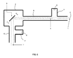
- Fig. 8
- in einer schematischen Ansicht ein weiteres Ausführungsbeispiel einer erfindungsgemäßen Vorrichtung, wobei dort in einer Röhre zwei unterschiedlich lange Röhrenzweige zur gleichzeitigen Dämmung zweier diskreter Schallfrequenzen vorgesehen sind,
- Fig. 9
- in einer schematischen Ansicht ein weiteres Ausführungsbeispiel einer erfindungsgemäßen Vorrichtung, wobei dort das Gehäuse eine Ein-und eine Austrittsöffnung mit Röhren aufweist, die beide mit einem Röhrenzweig zur beidseitigen Herbeiführung einer destruktiven Interferenz ausgestattet sind, wobei an der Innenwandung des Gehäuses zusätzliche akustische Absorber vorgesehen sind, und
- Fig. 10
- in einer schematischen Ansicht ein weiteres Ausführungsbeispiel einer erfindungsgemäßen Vorrichtung, wobei dort sowohl an der Innenwandung des Gehäuses als auch an der Innenwandung einer sehr lang ausgeführten Röhre akustische Absorber ausgebildet sind.
- Gemäß der Darstellung in
Fig. 1 umfasst die Vorrichtung zur Dämmung von Schall im optischen Strahlengang 1 eines in den Figuren nicht gezeigten Mikroskops ein nachfolgend als Gehäuse bezeichnetes Schallschutzgehäuse 2, welches zum Kapseln eines schallemittierenden Bauteils dient. Beispielhaft ist als Schallquelle ein schwingender Spiegel 3 als oszillierendes Strahlablenkmittel gezeigt. - Der Lichtstrahl 4 gelangt durch ein Fenster 5 in das Innere des Gehäuses 2, trifft dort auf den Spiegel 3 und wird entsprechend der Winkelstellung des Spielgels 3 in eine Röhre 6 durch diese hindurch geleitet, wobei die Röhre 6 eine Ein- bzw. Austrittsöffnung des Gehäuses 2 definiert.
- Zur Herbeiführung einer destruktiven Interferenz, nämlich zur weitgehenden Auslöschung des von dem hochfrequent schwingenden Spiegel 3 ausgehenden Schalls, weist die Röhre 6 einen Röhrenzweig 7 auf, der im Sinne eines Sacklochs ausgebildet ist, nämlich endseitig eine Schallreflexionswand 8 aufweist. Der Röhrenzweig 7 ragt seitlich, beispielsweise orthogonal, von der Röhre 6 ab und ist derart ausgestattet, bzw. dimensioniert, dass er gegenüber der in der Röhre 6 geradeaus laufenden Schallwelle eine Phasenänderung von 180° hervorruft, so dass die aus dem Röhrenzweig 7 reflektierte Schallwelle gemeinsam mit der geradeaus laufenden Schallwelle zur destruktiven Interferenz führt. Entsprechend kann die Länge des Röhrenzweigs 7 ein Viertel der akustischen Wellenlänge betragen.
- Bei dem in
Fig. 2 gezeigten Ausführungsbeispiel ist eine variable Abstimmung der Länge des Röhrenzweigs 7 möglich, wobei dort - lediglich symbolisch - die Schallreflexionswand 8 von einer einschiebbaren Stange 9 getragen ist. Die Schallreflexionswand 8 und die Stange 9 können im Sinne eines Kolbens mit Kolbenstange ausgeführt sein. Ein motorisierter bzw. hydraulisch/pneumatischer Betrieb ist insbesondere zur automatischen Anpassung bzw. Abstimmung des Röhrenzweigs 7 denkbar. - Bei dem in
Fig. 3 gezeigten Ausführungsbeispiel wird die Schallreflexionswand 8 über eine Schraube 10 betätigt, die wiederum manuell oder aber auch über einen elektrischen Motor, beispielsweise unter Nutzung einer Spindel, betätigbar bzw. antreibbar ist. Ansonsten entspricht das inFig. 3 gezeigte Ausführungsbeispiel den Ausführungsbeispielen aus denFig. 1 und2 . -
Fig. 4 zeigt ein weiteres Ausführungsbeispiel einer erfindungsgemäßen Vorrichtung, wobei dort die Röhre 6 mit einem Bypass 11 ausgestattet ist, dergestalt, dass der Bypass 11 um die halbe Schallwellenlänge länger ist als die parallele Wegstrecke durch die Röhre 6, so dass Schallwellen, die entlang der beiden möglichen Schallwege laufen, eine relative Phasendifferenz von 180° aufweisen. So ergibt sich am Ende der Röhre 6 kein Schalldruck, nämlich aufgrund der so erzeugten destruktiven Interferenz. -
Fig. 5 zeigt eine Abwandlung gegenüber dem Ausführungsbeispiel ausFig. 4 , wobei dort der Schall unmittelbar aus dem Gehäuse 2 heraus "entnommen" wird. Der Bypass 11 erstreckt sich somit vom Gehäuse 2 aus über eine seitliche Öffnung in die Röhre 6, so dass der über den Bypass 11 laufende Schall mit einer entsprechenden Phasenverzögerung mit dem Schall in der vom Lichtweg benutzten Öffnung zusammengeführt wird. Eine destruktive Interferenz lässt sich auch insoweit realisieren. - Das in
Fig. 6 gezeigte Ausführungsbeispiel definiert durch die Vorkehrung zweier Röhren 6 destruktive Interferenz verursachende Maßnahmen sowohl im Bereich einer optischen Eintrittsöffnung als auch einer optischen Austrittsöffnung. Die Vorkehrung eines Fensters entsprechend den Ausführungsbeispielen derFig. 1 bis 5 ist hier nicht erforderlich. Beide Röhren 6 sind mit jeweils einem Röhrenzweig 7 ausgestattet, wobei die beiden Röhrenzweige 7 entsprechend den voranstehenden Ausführungen zu denFig. 1 bis 5 arbeiten. - Das Ausführungsbeispiel aus
Fig. 7 ist in der einen Röhre 6 um einen weiteren - zweiten - Röhrenzweig ergänzt, nämlich zur Verstärkung der Schalldämmung, letztendlich durch die Sequenz zweier "Filter". Beide Röhrenzweige 7 sind identisch ausgebildet. - Das Ausführungsbeispiel aus
Fig. 8 unterscheidet sich von dem Ausführungsbeispiel ausFig. 7 in den die beiden Röhrenzweige 7 aufweisenden Röhren dadurch, dass die Röhrenzweige 7 unterschiedlich lang sind. Damit lassen sich zwei oder mehrere diskrete Schallfrequenzen gleichzeitig dämmen, nämlich entsprechend der Anzahl und Ausgestaltung der Röhrenzweige 7. - Wenngleich bei den in
Fig. 8 gezeigten Ausführungsbeispiel nur eine Röhre 6 vorgesehen ist, lassen sich hier entsprechend der Ausführungen aus denFig. 6 und7 auch zwei Röhren 6 unter Vermeidung eines Fensters 5 vorsehen. Beliebige entsprechende Merkmalskombinationen sind möglich. - Das Ausführungsbeispiel in
Fig. 9 entspricht im Wesentlichen dem Ausführungsbeispiel ausFig. 6 , wobei dort die Innenwandung des Gehäuses 2 mit akustischen Absorbern 12 ausgestattet ist. Dies ist insoweit von Vorteil, als durch die destruktive Interferenz an den optischen Öffnungen bzw. in den Röhren 6 die Schallenergie im Wesentlichen in das Gehäuse 2 zurückreflektiert wird. Die zusätzliche Vorkehrung der akustischen Absorber 12 ruft einen synergetischen Effekt mit den Maßnahmen zur destruktiven Interferenz hervor, wonach nämlich innerhalb des Gehäuses 2 eine Reduktion des Schallpegels durch die zusätzlich verwendeten Absorber 12 stattfindet. - Das in
Fig. 10 gezeigte Ausführungsbeispiel ist relevant bei Schallquellen mit variabler Frequenz, wobei dort sowohl im Innern des Gehäuses 2 als auch im Innern einer lang ausgeführt Röhre 6, jeweils an der Innenwandung, akustische Absorber 12 angeordnet bzw. ausgebildet sind. Eine solche Röhre 6 lässt sich im Rahmen einer sehr einfachen Ausgestaltung als optische Öffnung im Gehäuse 2 verwenden, ohne dabei den optischen Strahlengang zu beeinträchtigen. Eine Art Breitband-Absorber ist hier realisiert. - Auch hier hat die Auskleidung des Röhrensystems mit dem Absordermaterial eine erfindungsgemäße Wirkung im Sinne der destruktiven Interferenz: Da sich der Schall am Rand der Röhre aufgrund der Eigenschaften des Absorbermaterials langsamer oder zumindest mit anderer Geschwindigkeit fortbewegt als in der Mitte, kann sich aufgrund der Phasenverzögerung der am Rand verlaufenden Schallanteile gegenüber der in der Mitte verlaufenden Schallanteile insbesondere nach Vermischung der beiden Anteile über eine längere Laufstrecke eine destruktive Interferenz ausbilden, die letztendlich ebenfalls zu einer Schallunterdrückung nach außen hin führt.
- Hinsichtlich weiterer vorteilhafter Ausgestaltungen der erfindungsgemäßen Vorrichtung wird zur Vermeidung von Wiederholungen auf den allgemeinen Teil der Beschreibung sowie auf die beigefügten Patentansprüche verwiesen.
- Schließlich sei ausdrücklich darauf hingewiesen, dass die voranstehend beschriebenen Ausführungsbeispiele der erfindungsgemäßen Vorrichtung lediglich zur Erörterung der beanspruchten Lehre dienen, diese jedoch nicht auf die Ausführungsbeispiele einschränken.
-
- 1
- optischer Strahlengang
- 2
- Gehäuse, Schallschutzgehäuse
- 3
- Spiegel
- 4
- Lichtstrahl, Strahl
- 5
- Fenster
- 6
- Röhre
- 7
- Röhrenzweig
- 8
- Schallreflexionswand
- 9
- Stange
- 10
- Schraube
- 11
- Bypass
- 12
- Absorber
Claims (15)
- Vorrichtung zur Dämmung von Schall im optischen Strahlengang (1) eines Mikroskops, mit einem Schallschutzgehäuse (Gehäuse) (2) zum Kapseln eines Schall emittierenden Bauteils, vorzugsweise eines sich schnell bewegenden bzw. oszillierenden Strahlablenkmittels, insbesondere eines resonant schwingenden Spiegels (3), wobei das Gehäuse (2) mindestens eine optische Ein-/Austrittsöffnung (Öffnung) aufweist,
dadurch gekennzeichnet, dass das Gehäuse (2), vorzugsweise die Öffnung des Gehäuses, derart ausgebildet und/oder ausgestattet ist, dass der ansonsten aus dem Gehäuse (2) austretende Schall durch destruktive Interferenz weitgehend ausgelöscht ist, ohne dabei den optischen Strahl (4) zu beeinflussen. - Vorrichtung nach Anspruch 1, dadurch gekennzeichnet, dass eine optische Eintrittsöffnung und eine optische Austrittsöffnung als separate Öffnungen vorgesehen sind und dass beide Öffnungen in Bezug auf eine Schallemission nach dem gleichen Prinzip gedämmt sind.
- Vorrichtung nach Anspruch 1 oder 2, dadurch gekennzeichnet, dass die Öffnung durch eine sich vom Gehäuse (2) weg erstreckende Röhre (6) gebildet ist, wobei die Röhre (6) mit mindestens einem seitlich von der Röhre (6) abragenden Röhrenzweig (7) ausgestattet sein kann.
- Vorrichtung nach Anspruch 3, dadurch gekennzeichnet, dass die Röhre (6) mit zwei oder mehreren seitlich von der Röhre (6) abragenden Röhrenzweigen (7) ausgestattet ist.
- Vorrichtung nach Anspruch 3 oder 4, dadurch gekennzeichnet, dass der Röhrenzweig (7) endseitig geschlossen ist, vorzugsweise mittels einer Schallreflexionswand (8).
- Vorrichtung nach Anspruch 4 oder 5, dadurch gekennzeichnet, dass die Röhrenzweige (7) unterschiedlich ausgeführt sind, vorzugsweise unterschiedliche Tiefen aufweisen, insbesondere um unterschiedliche Schallfrequenzen gleichzeitig zu dämmen.
- Vorrichtung nach einem der Ansprüche 3 bis 6, dadurch gekennzeichnet, dass der Röhrenabzweig (7) derart beschaffen ist, dass Schallwellen, die in dem Röhrenabzweig (7) laufen und dort reflektiert werden, eine Phasenänderung von 180° gegenüber der in der Röhre (6) in Längsrichtung laufenden Welle erfahren und mit der in Längsrichtung laufenden Welle zur destruktiven Interferenz führen.
- Vorrichtung nach einem der Ansprüche 3 bis 7, dadurch gekennzeichnet, dass die Abstimmung des Röhrenzweigs (7) durch Anpassung von Breite/Durchmesser und/oder Länge des Röhrenzweigs (7) erfolgt.
- Vorrichtung nach Anspruch 8, dadurch gekennzeichnet, dass zur Veränderung der Länge des Röhrenzweigs (7) eine die Tiefe des Röhrenzweigs (7) veränderliche Schallreflexionswand (8) vorgesehen ist.
- Vorrichtung nach Anspruch 9, dadurch gekennzeichnet, dass die Schallreflexionswand (8) von einer endseitig in den Röhrenzweig (7) schraubbaren Einstellschraube (10) oder von einem einschiebbaren Einstellstift, einer Einstellstange oder einem Einstellkolben getragen oder gebildet ist.
- Vorrichtung nach Anspruch 10, dadurch gekennzeichnet, dass die Einstellung und somit die Abstimmung der Interferenzbedingungen im Röhrenzweig (7) motorisiert bzw. hydraulisch oder pneumatisch, erfolgt.
- Vorrichtung nach einem der Ansprüche 3 bis 11, dadurch gekennzeichnet, dass die Abstimmung des Röhrenzweigs (7) durch Wahl eines geeigneten Materials mit definiertem Schall-Absorptionsverhalten erfolgt.
- Vorrichtung nach einem der Ansprüche 3 bis 12, dadurch gekennzeichnet, dass der Röhrenzweig (7) als ein von der Röhre (6) abgehender und wieder in die Röhre (6) mündender Bypass (11) mit angepasster akustische Weglänge ausgeführt ist, wobei der Bypass (11) vorzugsweise eine um die halbe Schallwellenlänge längere akustische Wegstrecke als die Röhren (6) hat.
- Vorrichtung nach einem der Ansprüche 1 bis 13, dadurch gekennzeichnet, dass im Innern des Gehäuses (2) und/oder im Innern der Röhre(n) (6) akustische Absorber (12) vorgesehen sind, wobei die akustischen Absorber (12) als zumindest partielle Auskleidungen der jeweiligen Innenwandflächen ausgeführt sein können.
- Mikroskop, insbesondere Rastermikroskop, mit einer Vorrichtung nach einem der Ansprüche 1 bis 14.
Applications Claiming Priority (1)
| Application Number | Priority Date | Filing Date | Title |
|---|---|---|---|
| DE102012208250A DE102012208250A1 (de) | 2012-05-16 | 2012-05-16 | Vorrichtung zur Dämmung von Schall im optischen Strahlengang eines Mikroskops und Mikroskop mit einer entsprechenden Vorrichtung |
Publications (2)
| Publication Number | Publication Date |
|---|---|
| EP2665058A1 true EP2665058A1 (de) | 2013-11-20 |
| EP2665058B1 EP2665058B1 (de) | 2016-02-03 |
Family
ID=48182817
Family Applications (1)
| Application Number | Title | Priority Date | Filing Date |
|---|---|---|---|
| EP13165295.0A Not-in-force EP2665058B1 (de) | 2012-05-16 | 2013-04-25 | Mikroskop mit einer Vorrichtung zur Dämmung von Schall im optischen Strahlengang eines Mikroskops |
Country Status (5)
| Country | Link |
|---|---|
| US (1) | US8844671B2 (de) |
| EP (1) | EP2665058B1 (de) |
| JP (1) | JP6220550B2 (de) |
| CN (1) | CN103426426B (de) |
| DE (1) | DE102012208250A1 (de) |
Families Citing this family (5)
| Publication number | Priority date | Publication date | Assignee | Title |
|---|---|---|---|---|
| US8991500B2 (en) | 2013-04-24 | 2015-03-31 | Sabre Intellectual Property Holdings Llc | Fracturing operations employing chlorine dioxide |
| DE102016201439A1 (de) | 2016-02-01 | 2017-08-03 | Carl Zeiss Microscopy Gmbh | Gehäuse zur Aufnahme einer schwingenden Vorrichtung, Scanvorrichtung, Mikroskop und Verfahren |
| JP2018169546A (ja) * | 2017-03-30 | 2018-11-01 | 日本電産株式会社 | ハウジング、ハウジングユニット、およびケーシングユニット |
| PL3421945T3 (pl) * | 2017-06-29 | 2021-04-19 | Diehl Metering Gmbh | Sposób i urządzenie pomiarowe do określania wielkości opisującej płyn |
| DE102017006173A1 (de) * | 2017-06-29 | 2019-01-03 | Diehl Metering Gmbh | Messeinrichtung und Verfahren zur Ermittlung einer Fluidgröße |
Citations (5)
| Publication number | Priority date | Publication date | Assignee | Title |
|---|---|---|---|---|
| EP0618469A2 (de) * | 1993-03-31 | 1994-10-05 | Canon Kabushiki Kaisha | Optischer Strahlablenker |
| EP0741311A1 (de) * | 1995-05-04 | 1996-11-06 | Bayer Corporation | Optische Strahlabtastvorrichtung |
| US20060050346A1 (en) * | 2004-08-31 | 2006-03-09 | Samsung Electronics Co., Ltd. | Noise-reducing resonator and laser-scanning unit with the same |
| DE102004049437A1 (de) | 2004-10-19 | 2006-04-27 | Leica Microsystems Cms Gmbh | Strahlablenkeinrichtung und Rastermikroskop |
| US20100091083A1 (en) * | 2008-10-10 | 2010-04-15 | Yukio Itami | Optical scanning device and image forming apparatus |
Family Cites Families (28)
| Publication number | Priority date | Publication date | Assignee | Title |
|---|---|---|---|---|
| US1591088A (en) * | 1920-04-29 | 1926-07-06 | William H Holmes | Hydrocarbon motor |
| DE734858C (de) * | 1939-05-05 | 1943-04-29 | Eberspaecher J | Schalldaempfer, insbesondere fuer Brennkraftmaschinen |
| US2297046A (en) * | 1939-08-25 | 1942-09-29 | Maxim Silencer Co | Means for preventing shock excitation of acoustic conduits or chambers |
| US3323305A (en) * | 1964-10-16 | 1967-06-06 | Gen Motors Corp | Attenuating device |
| US3712412A (en) * | 1971-11-18 | 1973-01-23 | Environeering | Sound suppressing system |
| JPS5544404Y2 (de) * | 1974-05-09 | 1980-10-18 | ||
| US4479509A (en) * | 1981-08-03 | 1984-10-30 | E. I. Du Pont De Nemours And Company | Fluid control apparatus |
| US5033581A (en) * | 1989-10-02 | 1991-07-23 | Feuling Engineering, Inc. | Muffler for an internal combustion engine |
| KR950002473B1 (ko) * | 1992-04-15 | 1995-03-20 | 한국과학기술연구원 | 소음전달파이프의 경로차이를 이용한 능동소음 제어방법 및 장치 |
| JPH06214179A (ja) * | 1993-01-14 | 1994-08-05 | Nikon Corp | 共振スキャナの防音装置 |
| JPH06348280A (ja) * | 1993-06-03 | 1994-12-22 | Sekisui Chem Co Ltd | ダクト用消音装置 |
| KR0162203B1 (ko) | 1993-06-21 | 1998-12-15 | 김광호 | 양자화스텝사이즈의 가변을 이용한 적응적 부호화방법 및 그 장치 |
| JPH0829721A (ja) * | 1994-07-15 | 1996-02-02 | Fuji Xerox Co Ltd | 回転多面鏡駆動モータの制振、放熱装置 |
| CA2153855A1 (en) * | 1994-09-02 | 1996-03-03 | Donald Robert Demorest | Acoustic quarter wave tube absorber |
| JPH09177535A (ja) * | 1995-12-25 | 1997-07-08 | Tokyo Gas Co Ltd | 消音器 |
| JP3739463B2 (ja) * | 1995-12-29 | 2006-01-25 | 富士ゼロックス株式会社 | 光走査装置 |
| US6295363B1 (en) * | 1997-03-20 | 2001-09-25 | Digisonix, Inc. | Adaptive passive acoustic attenuation system |
| JPH116172A (ja) * | 1997-06-17 | 1999-01-12 | Hitachi Constr Mach Co Ltd | 消音装置 |
| EP1085200B1 (de) * | 1999-09-16 | 2003-01-02 | Siemens VDO Automotive Inc. | Veränderbarer Resonator |
| US6234758B1 (en) * | 1999-12-01 | 2001-05-22 | Caterpillar Inc. | Hydraulic noise reduction assembly with variable side branch |
| US6792907B1 (en) * | 2003-03-04 | 2004-09-21 | Visteon Global Technologies, Inc. | Helmholtz resonator |
| US20050194207A1 (en) * | 2004-03-04 | 2005-09-08 | York International Corporation | Apparatus and method of sound attenuation in a system employing a VSD and a quarter-wave resonator |
| US7337877B2 (en) * | 2004-03-12 | 2008-03-04 | Visteon Global Technologies, Inc. | Variable geometry resonator for acoustic control |
| US7497300B2 (en) * | 2004-03-18 | 2009-03-03 | D Angelo John P | Noise reduction tubes |
| US20070171502A1 (en) * | 2004-10-19 | 2007-07-26 | Leica Microsystems Cms Gmbh | Beam deflector and scanning microscope |
| EP2130201B1 (de) * | 2007-03-28 | 2014-05-07 | Mahle International GmbH | Helmholtz-resonator |
| JP2010210723A (ja) * | 2009-03-09 | 2010-09-24 | Nikon Corp | 走査型顕微鏡 |
| US8381871B1 (en) * | 2011-09-28 | 2013-02-26 | Visteon Global Technologies, Inc. | Compact low frequency resonator |
-
2012
- 2012-05-16 DE DE102012208250A patent/DE102012208250A1/de not_active Ceased
-
2013
- 2013-04-25 EP EP13165295.0A patent/EP2665058B1/de not_active Not-in-force
- 2013-05-14 JP JP2013101997A patent/JP6220550B2/ja not_active Expired - Fee Related
- 2013-05-15 US US13/894,726 patent/US8844671B2/en active Active
- 2013-05-16 CN CN201310181178.6A patent/CN103426426B/zh not_active Expired - Fee Related
Patent Citations (5)
| Publication number | Priority date | Publication date | Assignee | Title |
|---|---|---|---|---|
| EP0618469A2 (de) * | 1993-03-31 | 1994-10-05 | Canon Kabushiki Kaisha | Optischer Strahlablenker |
| EP0741311A1 (de) * | 1995-05-04 | 1996-11-06 | Bayer Corporation | Optische Strahlabtastvorrichtung |
| US20060050346A1 (en) * | 2004-08-31 | 2006-03-09 | Samsung Electronics Co., Ltd. | Noise-reducing resonator and laser-scanning unit with the same |
| DE102004049437A1 (de) | 2004-10-19 | 2006-04-27 | Leica Microsystems Cms Gmbh | Strahlablenkeinrichtung und Rastermikroskop |
| US20100091083A1 (en) * | 2008-10-10 | 2010-04-15 | Yukio Itami | Optical scanning device and image forming apparatus |
Non-Patent Citations (1)
| Title |
|---|
| JUNG Y H ET AL: "Reduction of aero-acoustic noise originating from a high-speed polygon mirror scanner motor in a laser beam printer utilizing air-flow analysis", MICROSYSTEM TECHNOLOGIES ; MICRO AND NANOSYSTEMS INFORMATION STORAGE AND PROCESSING SYSTEMS, SPRINGER, BERLIN, DE, vol. 17, no. 5 - 7, 5 February 2011 (2011-02-05), pages 771 - 776, XP019906795, ISSN: 1432-1858, DOI: 10.1007/S00542-011-1241-Y * |
Also Published As
| Publication number | Publication date |
|---|---|
| CN103426426B (zh) | 2017-06-09 |
| EP2665058B1 (de) | 2016-02-03 |
| JP2013238856A (ja) | 2013-11-28 |
| DE102012208250A1 (de) | 2013-11-21 |
| US8844671B2 (en) | 2014-09-30 |
| JP6220550B2 (ja) | 2017-10-25 |
| US20130306398A1 (en) | 2013-11-21 |
| CN103426426A (zh) | 2013-12-04 |
Similar Documents
| Publication | Publication Date | Title |
|---|---|---|
| EP2665058B1 (de) | Mikroskop mit einer Vorrichtung zur Dämmung von Schall im optischen Strahlengang eines Mikroskops | |
| DE10243449B4 (de) | CARS-Mikroskop und Verfahren zur CARS-Mikroskopie | |
| DE19906757B4 (de) | Mikroskop | |
| DE102007024075B4 (de) | Durchstimmbares akusto-optisches Filterelement, einstellbare Lichtquelle, Mikroskop und akusto-optischer Strahlteiler | |
| EP1421427B1 (de) | Optische anordnung und scanmikroskop | |
| DE102015015112B4 (de) | Vorrichtung und Verfahren zum Überwachen eines Bearbeitungsprozesses zur Materialbearbeitung mittels eines optischen Messstrahls | |
| DE3508193A1 (de) | Vorrichtung zur feststellung fluoreszierender stoffe an der erdoberflaeche | |
| EP1031055B1 (de) | Optische anordnung im strahlengang eines konfokalen fluoreszenzmikroskops | |
| EP3042233B1 (de) | Mikroskop mit einer akustooptischen vorrichtung | |
| EP3673289B1 (de) | Optische anordnung für ein lidar-system, lidar-system und arbeitsvorrichtung | |
| DE102008026484A1 (de) | Verfahren zum Erzeugen zweier optischer Pulse mit variablem, zeitlichem Pulsabstand | |
| DE102013227105A1 (de) | Mikroskop und akustooptischer Strahlvereiniger für ein Mikroskop | |
| EP3333611B1 (de) | Optisches gerät mit mindestens einem spektral selektiven bauelement | |
| DE10137158A1 (de) | Verfahren zur Scanmikroskopie und Scanmikroskop | |
| EP1911967A1 (de) | Laserzündvorrichtung | |
| DE112014007256T5 (de) | Systeme sowie Verfahren zum Schweißen unter Verwendung von Strahlformmitteln und Abschirmmitteln | |
| DE102009042199B4 (de) | Laserstrahl-Ausrichteinheit und Laserbearbeitungsgerät zur Bearbeitung eines Materials | |
| EP3740802B1 (de) | Akustooptische vorrichtung und verfahren | |
| DE19539683B4 (de) | Vorrichtung für Spektralanalyse mit kombinierter, komplementärer Filterung insbesondere für RAMAN-Spektrometrie | |
| DE102009011647B4 (de) | CARS-Endoskop | |
| DE102014117613B4 (de) | Laseranordnung und Verfahren zur Untersuchung eines Objektes | |
| DE102011077327A1 (de) | Strahlkombinierer zum Kombinieren von zwei jeweils eigenständig gescannten Beleuchtungsstrahlen eines Lichtrastermikroskops | |
| WO2007036531A1 (de) | Scanmikroskop und verfahren zur probenmanipulation mit einem manipulationslichtstrahl in einem scanmikroskop | |
| DE102011085929B3 (de) | Strahlweiche und Laserbearbeitungsanlage damit | |
| DE102013109479B3 (de) | Verfahren und Laseranordnung zum Bearbeiten eines Werkstücks mit einem gepulsten Laserstrahl |
Legal Events
| Date | Code | Title | Description |
|---|---|---|---|
| PUAI | Public reference made under article 153(3) epc to a published international application that has entered the european phase |
Free format text: ORIGINAL CODE: 0009012 |
|
| AK | Designated contracting states |
Kind code of ref document: A1 Designated state(s): AL AT BE BG CH CY CZ DE DK EE ES FI FR GB GR HR HU IE IS IT LI LT LU LV MC MK MT NL NO PL PT RO RS SE SI SK SM TR |
|
| AX | Request for extension of the european patent |
Extension state: BA ME |
|
| 17P | Request for examination filed |
Effective date: 20140520 |
|
| RBV | Designated contracting states (corrected) |
Designated state(s): AL AT BE BG CH CY CZ DE DK EE ES FI FR GB GR HR HU IE IS IT LI LT LU LV MC MK MT NL NO PL PT RO RS SE SI SK SM TR |
|
| 17Q | First examination report despatched |
Effective date: 20140916 |
|
| RIC1 | Information provided on ipc code assigned before grant |
Ipc: G10K 11/00 20060101ALI20141014BHEP Ipc: G02B 26/10 20060101ALI20141014BHEP Ipc: G10K 11/172 20060101AFI20141014BHEP Ipc: G10K 11/175 20060101ALI20141014BHEP Ipc: G02B 21/24 20060101ALI20141014BHEP |
|
| GRAP | Despatch of communication of intention to grant a patent |
Free format text: ORIGINAL CODE: EPIDOSNIGR1 |
|
| RAP1 | Party data changed (applicant data changed or rights of an application transferred) |
Owner name: LEICA MICROSYSTEMS CMS GMBH |
|
| INTG | Intention to grant announced |
Effective date: 20150325 |
|
| GRAP | Despatch of communication of intention to grant a patent |
Free format text: ORIGINAL CODE: EPIDOSNIGR1 |
|
| INTG | Intention to grant announced |
Effective date: 20150730 |
|
| GRAS | Grant fee paid |
Free format text: ORIGINAL CODE: EPIDOSNIGR3 |
|
| GRAA | (expected) grant |
Free format text: ORIGINAL CODE: 0009210 |
|
| AK | Designated contracting states |
Kind code of ref document: B1 Designated state(s): AL AT BE BG CH CY CZ DE DK EE ES FI FR GB GR HR HU IE IS IT LI LT LU LV MC MK MT NL NO PL PT RO RS SE SI SK SM TR |
|
| REG | Reference to a national code |
Ref country code: GB Ref legal event code: FG4D Free format text: NOT ENGLISH |
|
| REG | Reference to a national code |
Ref country code: AT Ref legal event code: REF Ref document number: 774021 Country of ref document: AT Kind code of ref document: T Effective date: 20160215 Ref country code: CH Ref legal event code: EP |
|
| REG | Reference to a national code |
Ref country code: IE Ref legal event code: FG4D Free format text: LANGUAGE OF EP DOCUMENT: GERMAN |
|
| REG | Reference to a national code |
Ref country code: DE Ref legal event code: R096 Ref document number: 502013001880 Country of ref document: DE |
|
| REG | Reference to a national code |
Ref country code: FR Ref legal event code: PLFP Year of fee payment: 4 |
|
| REG | Reference to a national code |
Ref country code: LT Ref legal event code: MG4D Ref country code: NL Ref legal event code: MP Effective date: 20160203 |
|
| PG25 | Lapsed in a contracting state [announced via postgrant information from national office to epo] |
Ref country code: IT Free format text: LAPSE BECAUSE OF FAILURE TO SUBMIT A TRANSLATION OF THE DESCRIPTION OR TO PAY THE FEE WITHIN THE PRESCRIBED TIME-LIMIT Effective date: 20160203 Ref country code: FI Free format text: LAPSE BECAUSE OF FAILURE TO SUBMIT A TRANSLATION OF THE DESCRIPTION OR TO PAY THE FEE WITHIN THE PRESCRIBED TIME-LIMIT Effective date: 20160203 Ref country code: NO Free format text: LAPSE BECAUSE OF FAILURE TO SUBMIT A TRANSLATION OF THE DESCRIPTION OR TO PAY THE FEE WITHIN THE PRESCRIBED TIME-LIMIT Effective date: 20160503 Ref country code: GR Free format text: LAPSE BECAUSE OF FAILURE TO SUBMIT A TRANSLATION OF THE DESCRIPTION OR TO PAY THE FEE WITHIN THE PRESCRIBED TIME-LIMIT Effective date: 20160504 Ref country code: HR Free format text: LAPSE BECAUSE OF FAILURE TO SUBMIT A TRANSLATION OF THE DESCRIPTION OR TO PAY THE FEE WITHIN THE PRESCRIBED TIME-LIMIT Effective date: 20160203 Ref country code: ES Free format text: LAPSE BECAUSE OF FAILURE TO SUBMIT A TRANSLATION OF THE DESCRIPTION OR TO PAY THE FEE WITHIN THE PRESCRIBED TIME-LIMIT Effective date: 20160203 |
|
| PG25 | Lapsed in a contracting state [announced via postgrant information from national office to epo] |
Ref country code: LT Free format text: LAPSE BECAUSE OF FAILURE TO SUBMIT A TRANSLATION OF THE DESCRIPTION OR TO PAY THE FEE WITHIN THE PRESCRIBED TIME-LIMIT Effective date: 20160203 Ref country code: IS Free format text: LAPSE BECAUSE OF FAILURE TO SUBMIT A TRANSLATION OF THE DESCRIPTION OR TO PAY THE FEE WITHIN THE PRESCRIBED TIME-LIMIT Effective date: 20160603 Ref country code: NL Free format text: LAPSE BECAUSE OF FAILURE TO SUBMIT A TRANSLATION OF THE DESCRIPTION OR TO PAY THE FEE WITHIN THE PRESCRIBED TIME-LIMIT Effective date: 20160203 Ref country code: PL Free format text: LAPSE BECAUSE OF FAILURE TO SUBMIT A TRANSLATION OF THE DESCRIPTION OR TO PAY THE FEE WITHIN THE PRESCRIBED TIME-LIMIT Effective date: 20160203 Ref country code: LV Free format text: LAPSE BECAUSE OF FAILURE TO SUBMIT A TRANSLATION OF THE DESCRIPTION OR TO PAY THE FEE WITHIN THE PRESCRIBED TIME-LIMIT Effective date: 20160203 Ref country code: PT Free format text: LAPSE BECAUSE OF FAILURE TO SUBMIT A TRANSLATION OF THE DESCRIPTION OR TO PAY THE FEE WITHIN THE PRESCRIBED TIME-LIMIT Effective date: 20160603 Ref country code: RS Free format text: LAPSE BECAUSE OF FAILURE TO SUBMIT A TRANSLATION OF THE DESCRIPTION OR TO PAY THE FEE WITHIN THE PRESCRIBED TIME-LIMIT Effective date: 20160203 Ref country code: SE Free format text: LAPSE BECAUSE OF FAILURE TO SUBMIT A TRANSLATION OF THE DESCRIPTION OR TO PAY THE FEE WITHIN THE PRESCRIBED TIME-LIMIT Effective date: 20160203 Ref country code: BE Free format text: LAPSE BECAUSE OF NON-PAYMENT OF DUE FEES Effective date: 20160430 |
|
| PG25 | Lapsed in a contracting state [announced via postgrant information from national office to epo] |
Ref country code: EE Free format text: LAPSE BECAUSE OF FAILURE TO SUBMIT A TRANSLATION OF THE DESCRIPTION OR TO PAY THE FEE WITHIN THE PRESCRIBED TIME-LIMIT Effective date: 20160203 Ref country code: DK Free format text: LAPSE BECAUSE OF FAILURE TO SUBMIT A TRANSLATION OF THE DESCRIPTION OR TO PAY THE FEE WITHIN THE PRESCRIBED TIME-LIMIT Effective date: 20160203 |
|
| REG | Reference to a national code |
Ref country code: DE Ref legal event code: R097 Ref document number: 502013001880 Country of ref document: DE |
|
| PG25 | Lapsed in a contracting state [announced via postgrant information from national office to epo] |
Ref country code: SM Free format text: LAPSE BECAUSE OF FAILURE TO SUBMIT A TRANSLATION OF THE DESCRIPTION OR TO PAY THE FEE WITHIN THE PRESCRIBED TIME-LIMIT Effective date: 20160203 Ref country code: RO Free format text: LAPSE BECAUSE OF FAILURE TO SUBMIT A TRANSLATION OF THE DESCRIPTION OR TO PAY THE FEE WITHIN THE PRESCRIBED TIME-LIMIT Effective date: 20160203 Ref country code: SK Free format text: LAPSE BECAUSE OF FAILURE TO SUBMIT A TRANSLATION OF THE DESCRIPTION OR TO PAY THE FEE WITHIN THE PRESCRIBED TIME-LIMIT Effective date: 20160203 Ref country code: CZ Free format text: LAPSE BECAUSE OF FAILURE TO SUBMIT A TRANSLATION OF THE DESCRIPTION OR TO PAY THE FEE WITHIN THE PRESCRIBED TIME-LIMIT Effective date: 20160203 |
|
| REG | Reference to a national code |
Ref country code: CH Ref legal event code: PL |
|
| PLBE | No opposition filed within time limit |
Free format text: ORIGINAL CODE: 0009261 |
|
| STAA | Information on the status of an ep patent application or granted ep patent |
Free format text: STATUS: NO OPPOSITION FILED WITHIN TIME LIMIT |
|
| PG25 | Lapsed in a contracting state [announced via postgrant information from national office to epo] |
Ref country code: LU Free format text: LAPSE BECAUSE OF FAILURE TO SUBMIT A TRANSLATION OF THE DESCRIPTION OR TO PAY THE FEE WITHIN THE PRESCRIBED TIME-LIMIT Effective date: 20160425 |
|
| 26N | No opposition filed |
Effective date: 20161104 |
|
| REG | Reference to a national code |
Ref country code: IE Ref legal event code: MM4A |
|
| PG25 | Lapsed in a contracting state [announced via postgrant information from national office to epo] |
Ref country code: LI Free format text: LAPSE BECAUSE OF NON-PAYMENT OF DUE FEES Effective date: 20160430 Ref country code: CH Free format text: LAPSE BECAUSE OF NON-PAYMENT OF DUE FEES Effective date: 20160430 |
|
| PG25 | Lapsed in a contracting state [announced via postgrant information from national office to epo] |
Ref country code: SI Free format text: LAPSE BECAUSE OF FAILURE TO SUBMIT A TRANSLATION OF THE DESCRIPTION OR TO PAY THE FEE WITHIN THE PRESCRIBED TIME-LIMIT Effective date: 20160203 Ref country code: BG Free format text: LAPSE BECAUSE OF FAILURE TO SUBMIT A TRANSLATION OF THE DESCRIPTION OR TO PAY THE FEE WITHIN THE PRESCRIBED TIME-LIMIT Effective date: 20160503 |
|
| REG | Reference to a national code |
Ref country code: FR Ref legal event code: PLFP Year of fee payment: 5 |
|
| PG25 | Lapsed in a contracting state [announced via postgrant information from national office to epo] |
Ref country code: IE Free format text: LAPSE BECAUSE OF NON-PAYMENT OF DUE FEES Effective date: 20160425 |
|
| REG | Reference to a national code |
Ref country code: FR Ref legal event code: PLFP Year of fee payment: 6 |
|
| PG25 | Lapsed in a contracting state [announced via postgrant information from national office to epo] |
Ref country code: CY Free format text: LAPSE BECAUSE OF FAILURE TO SUBMIT A TRANSLATION OF THE DESCRIPTION OR TO PAY THE FEE WITHIN THE PRESCRIBED TIME-LIMIT Effective date: 20160203 Ref country code: HU Free format text: LAPSE BECAUSE OF FAILURE TO SUBMIT A TRANSLATION OF THE DESCRIPTION OR TO PAY THE FEE WITHIN THE PRESCRIBED TIME-LIMIT; INVALID AB INITIO Effective date: 20130425 |
|
| PG25 | Lapsed in a contracting state [announced via postgrant information from national office to epo] |
Ref country code: TR Free format text: LAPSE BECAUSE OF FAILURE TO SUBMIT A TRANSLATION OF THE DESCRIPTION OR TO PAY THE FEE WITHIN THE PRESCRIBED TIME-LIMIT Effective date: 20160203 Ref country code: MK Free format text: LAPSE BECAUSE OF FAILURE TO SUBMIT A TRANSLATION OF THE DESCRIPTION OR TO PAY THE FEE WITHIN THE PRESCRIBED TIME-LIMIT Effective date: 20160203 Ref country code: MT Free format text: LAPSE BECAUSE OF FAILURE TO SUBMIT A TRANSLATION OF THE DESCRIPTION OR TO PAY THE FEE WITHIN THE PRESCRIBED TIME-LIMIT Effective date: 20160203 Ref country code: MC Free format text: LAPSE BECAUSE OF FAILURE TO SUBMIT A TRANSLATION OF THE DESCRIPTION OR TO PAY THE FEE WITHIN THE PRESCRIBED TIME-LIMIT Effective date: 20160203 |
|
| PG25 | Lapsed in a contracting state [announced via postgrant information from national office to epo] |
Ref country code: AL Free format text: LAPSE BECAUSE OF FAILURE TO SUBMIT A TRANSLATION OF THE DESCRIPTION OR TO PAY THE FEE WITHIN THE PRESCRIBED TIME-LIMIT Effective date: 20160203 |
|
| REG | Reference to a national code |
Ref country code: AT Ref legal event code: MM01 Ref document number: 774021 Country of ref document: AT Kind code of ref document: T Effective date: 20180425 |
|
| PG25 | Lapsed in a contracting state [announced via postgrant information from national office to epo] |
Ref country code: AT Free format text: LAPSE BECAUSE OF NON-PAYMENT OF DUE FEES Effective date: 20180425 |
|
| P01 | Opt-out of the competence of the unified patent court (upc) registered |
Effective date: 20230414 |
|
| PGFP | Annual fee paid to national office [announced via postgrant information from national office to epo] |
Ref country code: FR Payment date: 20230421 Year of fee payment: 11 Ref country code: DE Payment date: 20230427 Year of fee payment: 11 |
|
| PGFP | Annual fee paid to national office [announced via postgrant information from national office to epo] |
Ref country code: GB Payment date: 20230418 Year of fee payment: 11 |
|
| REG | Reference to a national code |
Ref country code: DE Ref legal event code: R119 Ref document number: 502013001880 Country of ref document: DE |
|
| GBPC | Gb: european patent ceased through non-payment of renewal fee |
Effective date: 20240425 |
|
| PG25 | Lapsed in a contracting state [announced via postgrant information from national office to epo] |
Ref country code: DE Free format text: LAPSE BECAUSE OF NON-PAYMENT OF DUE FEES Effective date: 20241105 |
|
| PG25 | Lapsed in a contracting state [announced via postgrant information from national office to epo] |
Ref country code: GB Free format text: LAPSE BECAUSE OF NON-PAYMENT OF DUE FEES Effective date: 20240425 |
|
| PG25 | Lapsed in a contracting state [announced via postgrant information from national office to epo] |
Ref country code: FR Free format text: LAPSE BECAUSE OF NON-PAYMENT OF DUE FEES Effective date: 20240430 |
|
| PG25 | Lapsed in a contracting state [announced via postgrant information from national office to epo] |
Ref country code: GB Free format text: LAPSE BECAUSE OF NON-PAYMENT OF DUE FEES Effective date: 20240425 Ref country code: FR Free format text: LAPSE BECAUSE OF NON-PAYMENT OF DUE FEES Effective date: 20240430 Ref country code: DE Free format text: LAPSE BECAUSE OF NON-PAYMENT OF DUE FEES Effective date: 20241105 |