EP2662310A1 - Frame member for packaging flat items and packaging made up of such elements - Google Patents
Frame member for packaging flat items and packaging made up of such elements Download PDFInfo
- Publication number
- EP2662310A1 EP2662310A1 EP13166574.7A EP13166574A EP2662310A1 EP 2662310 A1 EP2662310 A1 EP 2662310A1 EP 13166574 A EP13166574 A EP 13166574A EP 2662310 A1 EP2662310 A1 EP 2662310A1
- Authority
- EP
- European Patent Office
- Prior art keywords
- frame element
- element according
- profiles
- crenellations
- packaging
- Prior art date
- Legal status (The legal status is an assumption and is not a legal conclusion. Google has not performed a legal analysis and makes no representation as to the accuracy of the status listed.)
- Granted
Links
- 238000004806 packaging method and process Methods 0.000 title claims description 14
- 230000035939 shock Effects 0.000 claims description 9
- 238000013016 damping Methods 0.000 claims description 5
- 238000007747 plating Methods 0.000 claims description 4
- 230000000295 complement effect Effects 0.000 claims description 3
- 238000010521 absorption reaction Methods 0.000 claims description 2
- 230000000903 blocking effect Effects 0.000 abstract 1
- 239000000463 material Substances 0.000 description 7
- 230000002093 peripheral effect Effects 0.000 description 3
- 230000001413 cellular effect Effects 0.000 description 2
- 230000001143 conditioned effect Effects 0.000 description 2
- 239000000470 constituent Substances 0.000 description 2
- 239000004793 Polystyrene Substances 0.000 description 1
- 239000004794 expanded polystyrene Substances 0.000 description 1
- 239000000835 fiber Substances 0.000 description 1
- 238000009432 framing Methods 0.000 description 1
- 235000021189 garnishes Nutrition 0.000 description 1
- 239000011521 glass Substances 0.000 description 1
- 239000008187 granular material Substances 0.000 description 1
- 238000009434 installation Methods 0.000 description 1
- 238000007726 management method Methods 0.000 description 1
- 238000004519 manufacturing process Methods 0.000 description 1
- 238000010422 painting Methods 0.000 description 1
- 239000002245 particle Substances 0.000 description 1
- 229920002223 polystyrene Polymers 0.000 description 1
- 238000004064 recycling Methods 0.000 description 1
Images


Classifications
-
- B—PERFORMING OPERATIONS; TRANSPORTING
- B65—CONVEYING; PACKING; STORING; HANDLING THIN OR FILAMENTARY MATERIAL
- B65D—CONTAINERS FOR STORAGE OR TRANSPORT OF ARTICLES OR MATERIALS, e.g. BAGS, BARRELS, BOTTLES, BOXES, CANS, CARTONS, CRATES, DRUMS, JARS, TANKS, HOPPERS, FORWARDING CONTAINERS; ACCESSORIES, CLOSURES, OR FITTINGS THEREFOR; PACKAGING ELEMENTS; PACKAGES
- B65D81/00—Containers, packaging elements, or packages, for contents presenting particular transport or storage problems, or adapted to be used for non-packaging purposes after removal of contents
- B65D81/02—Containers, packaging elements, or packages, for contents presenting particular transport or storage problems, or adapted to be used for non-packaging purposes after removal of contents specially adapted to protect contents from mechanical damage
- B65D81/05—Containers, packaging elements, or packages, for contents presenting particular transport or storage problems, or adapted to be used for non-packaging purposes after removal of contents specially adapted to protect contents from mechanical damage maintaining contents at spaced relation from package walls, or from other contents
- B65D81/053—Corner, edge or end protectors
- B65D81/057—Protectors contacting four surfaces of the packaged article, e.g. four-sided corner protectors
-
- B—PERFORMING OPERATIONS; TRANSPORTING
- B65—CONVEYING; PACKING; STORING; HANDLING THIN OR FILAMENTARY MATERIAL
- B65D—CONTAINERS FOR STORAGE OR TRANSPORT OF ARTICLES OR MATERIALS, e.g. BAGS, BARRELS, BOTTLES, BOXES, CANS, CARTONS, CRATES, DRUMS, JARS, TANKS, HOPPERS, FORWARDING CONTAINERS; ACCESSORIES, CLOSURES, OR FITTINGS THEREFOR; PACKAGING ELEMENTS; PACKAGES
- B65D25/00—Details of other kinds or types of rigid or semi-rigid containers
- B65D25/20—External fittings
-
- B—PERFORMING OPERATIONS; TRANSPORTING
- B65—CONVEYING; PACKING; STORING; HANDLING THIN OR FILAMENTARY MATERIAL
- B65D—CONTAINERS FOR STORAGE OR TRANSPORT OF ARTICLES OR MATERIALS, e.g. BAGS, BARRELS, BOTTLES, BOXES, CANS, CARTONS, CRATES, DRUMS, JARS, TANKS, HOPPERS, FORWARDING CONTAINERS; ACCESSORIES, CLOSURES, OR FITTINGS THEREFOR; PACKAGING ELEMENTS; PACKAGES
- B65D77/00—Packages formed by enclosing articles or materials in preformed containers, e.g. boxes, cartons, sacks or bags
- B65D77/22—Details
- B65D77/24—Inserts or accessories added or incorporated during filling of containers
- B65D77/26—Elements or devices for locating or protecting articles
-
- B—PERFORMING OPERATIONS; TRANSPORTING
- B65—CONVEYING; PACKING; STORING; HANDLING THIN OR FILAMENTARY MATERIAL
- B65D—CONTAINERS FOR STORAGE OR TRANSPORT OF ARTICLES OR MATERIALS, e.g. BAGS, BARRELS, BOTTLES, BOXES, CANS, CARTONS, CRATES, DRUMS, JARS, TANKS, HOPPERS, FORWARDING CONTAINERS; ACCESSORIES, CLOSURES, OR FITTINGS THEREFOR; PACKAGING ELEMENTS; PACKAGES
- B65D85/00—Containers, packaging elements or packages, specially adapted for particular articles or materials
- B65D85/30—Containers, packaging elements or packages, specially adapted for particular articles or materials for articles particularly sensitive to damage by shock or pressure
- B65D85/48—Containers, packaging elements or packages, specially adapted for particular articles or materials for articles particularly sensitive to damage by shock or pressure for glass sheets
-
- B—PERFORMING OPERATIONS; TRANSPORTING
- B65—CONVEYING; PACKING; STORING; HANDLING THIN OR FILAMENTARY MATERIAL
- B65D—CONTAINERS FOR STORAGE OR TRANSPORT OF ARTICLES OR MATERIALS, e.g. BAGS, BARRELS, BOTTLES, BOXES, CANS, CARTONS, CRATES, DRUMS, JARS, TANKS, HOPPERS, FORWARDING CONTAINERS; ACCESSORIES, CLOSURES, OR FITTINGS THEREFOR; PACKAGING ELEMENTS; PACKAGES
- B65D2581/00—Containers, packaging elements, or packages, for contents presenting particular transport or storage problems, or adapted to be used for non-packaging purposes after removal of contents
- B65D2581/02—Containers, packaging elements, or packages, for contents presenting particular transport or storage problems, or adapted to be used for non-packaging purposes after removal of contents specially adapted to protect contents from mechanical damage
- B65D2581/05—Containers, packaging elements, or packages, for contents presenting particular transport or storage problems, or adapted to be used for non-packaging purposes after removal of contents specially adapted to protect contents from mechanical damage maintaining contents at spaced relation from package walls, or from other contents
- B65D2581/051—Details of packaging elements for maintaining contents at spaced relation from package walls, or from other contents
- B65D2581/052—Materials
- B65D2581/055—Plastic in general, e.g. foamed plastic, molded plastic, extruded plastic
-
- B—PERFORMING OPERATIONS; TRANSPORTING
- B65—CONVEYING; PACKING; STORING; HANDLING THIN OR FILAMENTARY MATERIAL
- B65D—CONTAINERS FOR STORAGE OR TRANSPORT OF ARTICLES OR MATERIALS, e.g. BAGS, BARRELS, BOTTLES, BOXES, CANS, CARTONS, CRATES, DRUMS, JARS, TANKS, HOPPERS, FORWARDING CONTAINERS; ACCESSORIES, CLOSURES, OR FITTINGS THEREFOR; PACKAGING ELEMENTS; PACKAGES
- B65D81/00—Containers, packaging elements, or packages, for contents presenting particular transport or storage problems, or adapted to be used for non-packaging purposes after removal of contents
- B65D81/02—Containers, packaging elements, or packages, for contents presenting particular transport or storage problems, or adapted to be used for non-packaging purposes after removal of contents specially adapted to protect contents from mechanical damage
- B65D81/05—Containers, packaging elements, or packages, for contents presenting particular transport or storage problems, or adapted to be used for non-packaging purposes after removal of contents specially adapted to protect contents from mechanical damage maintaining contents at spaced relation from package walls, or from other contents
- B65D81/053—Corner, edge or end protectors
Definitions
- the present invention relates to a frame element for the packaging of flat articles and the packaging obtained by the combination of such elements.
- the present invention relates more particularly to an element intended to form all or part of a frame ensuring the protection of articles or substantially flat products during storage and / or transport.
- flat article is meant a product whose thickness is significantly lower than its other dimensions.
- These articles may have a general shape of parallelepiped, cylinder, polygon or some form and complex.
- Such a framework element finds its application, especially in the field of logistics for the packaging and delivery of products and flat and fragile equipment such as in particular, flat screens of televisions, glass panels, paintings, ...
- these large flat articles are packaged in containers such as wooden or cardboard boxes in which they are immobilized by wedges and protected from possible shocks by particles (granules or balls) of cellular material (polystyrene) fibers, associated, where appropriate, with other packaging elements.
- containers such as wooden or cardboard boxes in which they are immobilized by wedges and protected from possible shocks by particles (granules or balls) of cellular material (polystyrene) fibers, associated, where appropriate, with other packaging elements.
- the present invention aims to solve these technical problems satisfactorily by proposing a solution for filling and protecting the thickness of these flat articles efficiently and compactly.
- a frame element for the packaging of flat articles characterized in that it comprises at least a first section and a second section connected, longitudinally and in one piece, by a flexible hinge and each having an axial receiving groove of the article which is delimited laterally by two series of crenellations; the respective slots of said profiles, adjacent to said hinge, being provided with contact stops ensuring the locking of the two profiles in a relative angular position where their respective grooves are open opposite the edge of the article to be protected.
- said slots are configured and positioned so that two identical elements are superposed in an inverted manner and head-to-tail by interlocking the first and second profiles.
- the crenellations of one of the series of the first profile consist of an inner projection with a straight wall extended externally by a transverse shoulder.
- crenellations of one of the series of the second section are separated by external flats extended internally by bodies.
- the slots of at least one of the series of the first profile are provided with underlying cells of damping shocks.
- the second section is provided with a single underlying longitudinal cavity for damping shocks.
- the frame member comprises more than two articulated sections.
- said stops are formed of inclined faces extending at the inner end of the first and second sections, on either side of the hinge.
- the frame element of the invention comprises locking members of the contact abutments.
- These locking members are preferably constituted by a lug carried by the second profile and whose face facing the first profile abuts against the outer transverse shoulder of the immediately adjacent crenel while the corresponding projection is housed in the remains facing.
- said crenellations are made in the form of triangular teeth.
- said flexible hinge is designed to allow folding of the two profiles at an angle of 180 ° with respect to each other, at least rearward.
- the profiles of the lower faces of the two profiles are complementary to allow their interlocking or their plating after retracting 180 ° to the rear.
- Another object of the invention is a package made by the combination of one or more frame elements previously described for the packaging of flat articles.
- the frame element of the invention makes it possible to offer ergonomic and economical packaging for products whose flat shape and fragility make the handling and delivery operations difficult and delicate for the manufacturer, the carrier, the user or the user. the consumer.
- the frame element of the invention has a simple structure, made in one piece and whose manufacture and installation are easy to implement industrially.
- This framing element can be used as it is mounted on the peripheral edge of the article or associated with a container forming an outer envelope, optionally waterproof and hermetic, depending on the nature of the article to be packaged.
- the structure of this element is self-supporting by attaching removably to the thickness of the article and is adapted to different sizes and types of flat articles without significant changes are necessary.
- the protection obtained is remarkable because, besides the wedging and the support of the article, the possible shocks are strongly damped and / or absorbed by dedicated means, carried by the frame element itself and to preserve the article. conditioned of any damage.
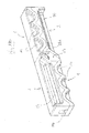
- the frame element shown in the figures is, in the free state, in the form of a single elongate piece comprising at least a first section 1 and a second section 2 of the same width longitudinally connected by a flexible hinge 3.
- Each of the profiles 1, 2 has an axial groove 10, 20 in which is housed the peripheral edge of the flat article P (shown in FIG. figure 4 ) in the manner of a strip.
- the frame element is preferably made of a deformable cellular material (expanded polystyrene type) which makes it possible to engage the edge of the flat article in force. in the groove 10, 20 and ensure, by wedging, a good mechanical strength of the assembly.
- a deformable cellular material expanded polystyrene type
- a relative elasticity of the material can reinforce the clamping in the groove and the plating of the profiles 1, 2 on the peripheral flat faces of the article P.
- This groove is delimited laterally and on each profile, by flanks consisting of two parallel series of crenellations 11, 12, 21, 22.
- the crenellations are made in the form of substantially triangular teeth.
- At least one of the profiles could have a curvature to mount the element on all or part of an article whose edges would not be straight.
- stops provide locking in an angular orientation different from 90 °, adapted to the specific contours and profile of the flat article to be packaged.
- the respective grooves 10, 20 of the profiles 1, 2 are connected and are open in jaw towards the inside of the angle and facing each other to receive the corners and edges of the flat article P, in the manner of a frame.
- the hinge 3 is closed, it is positioned in the corners of the flat article, as shown on the figure 4 .
- the flexible hinge 3 is of a type known per se and consists of a thinned area of the constituent material of the element preferably located in the median position between the profiles 1, 2. This hinge allows the elastic folding of the two profiles relative to each other.
- crenellations 11, 12, 21, 22 are configured and positioned so that two identical elements can be superposed in an inverted manner and head-to-tail by co-fitting of the first and second profiles, as shown in FIGS. Figures 3A , 3B .
- the crenellations 12 of one of the two series of the first profile 1 consist of an inner projection 121 with a straight wall extended externally by a transverse shoulder 122 ( figures 1 , 2 , 5A and 5B ), while the crenellations 22 of one of the series of the second section 2 are separated by outer flats 222 extended internally by bodies 221.
- crenellations 11, 21 of the other series of the two sections 1, 2 are identical as is visible on the figure 2 .
- the profile of the flange 221 of the second section 2 is adapted to receive, by interlocking, the projection 121 of the crenel 12 facing the first profile 1 during the stacking of two elements, as shown in FIGS. Figures 3A , 3B .
- the protrusions 121 and the struts 221 are made on the same side of the element, as shown in FIG. figure 2 .
- Such a stack is very compact and offers a very small footprint.
- the stops are formed of inclined faces 13, 23 extending at the inner end respectively of the first and second sections 1, 2, on either side of the hinge 3.
- the groove 20 of the second section 2 is located at a level greater than that of the groove 10 of the first section 1, as shown in FIG. figure 1 .
- the locking members are, in turn, constituted by a lug carried by the crenel 22a of the second section 2 and whose face 23a, facing the first section 1, bears against the outer transverse shoulder 122a of the crenel 12a immediately adjacent while the corresponding projection 121 is housed in the recess 221 facing, as shown in the figure 2 .
- the slots of at least one of the series (and here the crenellations 12) of the section 1 are provided with cells 14 underlying providing damping shocks.
- the second section 2 is provided, meanwhile, a single cavity 24 underlying longitudinal damping shocks.
- the cells 14 and the cavity 24 are made of same side of both profiles 1, 2 but it is possible to position them, as needed, on two opposite sides.
- the cells 14 and the cavity 24 thus form recessed areas of absorption of the kinetic energy that is likely to be communicated incidentally to the package during impacts (drop, shock, ...), thus preserving the integrity of the article.
- the longitudinal cavity 24 may, where appropriate, serve as an ergonomic compartment for receiving accessories of the article to be packaged.
- the element comprises more than two profiles.
- the profiles are then articulated to each other in the manner of a bicycle chain and come close to garnish and surrounding, the perimeter of the article P.
- the second section 2 is intended to be mounted on the lower part of the flat article P so as to provide a base for the package thus formed, as shown in FIG. figure 4 .
- the end walls of the longitudinal cavity 24 are advantageously oriented in abutment and, where appropriate, reinforced to ensure better stability.
- the flexible hinge 3 is more particularly adapted and intended to allow elastic folding in both directions.
- FIG. 7A and 7B illustrate, for their part, the folding of the two profiles towards the rear (opening direction shown in FIG. Figure 7A arrow) at an angle of 180 ° to each other.
- the amplitude of 180 ° was not necessary for a folding closure as described above whose purpose was to ensure the protection of the corners of a flat article. Moreover, the presence of the slots could hinder a folding closure 180 °, unless they are specifically adapted to such folding.
- the folding is more particularly intended to facilitate the packaging and transport of the frame elements themselves.
- the outer or back faces 15, 25 of the two sections 1, 2 will be flat ( Figures 7A, 7B ) or their profiles will be complementary to allow their nesting or plating back to back after flap 180 ° backwards.
Abstract
Description
La présente invention concerne un élément de cadre pour le conditionnement d'articles plats ainsi que l'emballage obtenu par l'association de tels éléments.The present invention relates to a frame element for the packaging of flat articles and the packaging obtained by the combination of such elements.
La présente invention se rapporte plus particulièrement à un élément destiné à former tout ou partie d'un cadre assurant la protection d'articles ou de produits sensiblement plats lors de leur stockage et/ou leur transport.The present invention relates more particularly to an element intended to form all or part of a frame ensuring the protection of articles or substantially flat products during storage and / or transport.
On entend par article plat un produit dont l'épaisseur est notablement plus faible que ses autres dimensions.By flat article is meant a product whose thickness is significantly lower than its other dimensions.
Ces articles peuvent avoir une forme générale de parallélépipède, de cylindre, de polygone ou une forme quelconque et complexe.These articles may have a general shape of parallelepiped, cylinder, polygon or some form and complex.
Un tel élément de cadre trouve son application, notamment, dans le domaine de la logistique pour le conditionnement et la livraison de produits ou d'équipements plats et fragiles tels qu'en particulier, des écrans plats de téléviseurs, des panneaux de verre, des tableaux, ...Such a framework element finds its application, especially in the field of logistics for the packaging and delivery of products and flat and fragile equipment such as in particular, flat screens of televisions, glass panels, paintings, ...
En général, ces articles plats de grandes dimensions sont conditionnés dans des conteneurs tels que des caisses en bois ou en carton dans lesquelles ils sont immobilisés par des cales et protégés des chocs éventuels par des particules (granulés ou billes) de matériau alvéolaire (polystyrène), des fibres, associées, le cas échéant, à d'autres éléments d'emballage.In general, these large flat articles are packaged in containers such as wooden or cardboard boxes in which they are immobilized by wedges and protected from possible shocks by particles (granules or balls) of cellular material (polystyrene) fibers, associated, where appropriate, with other packaging elements.
Cependant, ces moyens de protection utilisent des volumes importants d'éléments disparates et de matières différentes dont tant l'acheminement jusqu'au lieu de conditionnement que la gestion ultérieure, après utilisation, pose des problèmes d'encombrement, de recyclage et donc de coûts.However, these means of protection use large volumes of disparate elements and different materials which both the routing to the packaging site and subsequent management, after use, poses problems of congestion, recycling and therefore costs .
La présente invention a pour but de résoudre ces problèmes techniques de manière satisfaisante en proposant une solution permettant de garnir et de protéger l'épaisseur de ces articles plats de façon efficace et compacte.The present invention aims to solve these technical problems satisfactorily by proposing a solution for filling and protecting the thickness of these flat articles efficiently and compactly.
Ce but est atteint selon l'invention au moyen d'un élément de cadre pour le conditionnement d'articles plats, caractérisé en ce qu'il comprend au moins un premier profilé et un second profilé reliés, longitudinalement et en une seule pièce, par une charnière souple et comportant chacun une gorge axiale de réception de l'article qui est délimitée latéralement par deux séries de créneaux ; les créneaux respectifs desdits profilés, adjacents à ladite charnière, étant pourvus de butées de contact assurant le blocage des deux profilés dans une position angulaire relative où leurs gorges respectives sont ouvertes en regard du bord de l'article à protéger.This object is achieved according to the invention by means of a frame element for the packaging of flat articles, characterized in that it comprises at least a first section and a second section connected, longitudinally and in one piece, by a flexible hinge and each having an axial receiving groove of the article which is delimited laterally by two series of crenellations; the respective slots of said profiles, adjacent to said hinge, being provided with contact stops ensuring the locking of the two profiles in a relative angular position where their respective grooves are open opposite the edge of the article to be protected.
Selon une caractéristique avantageuse, lesdits créneaux sont configurés et positionnés de telle sorte que deux éléments identiques se superposent de façon inversée et tête-bêche par emboîtement des premier et second profilés.According to an advantageous characteristic, said slots are configured and positioned so that two identical elements are superposed in an inverted manner and head-to-tail by interlocking the first and second profiles.
Selon une autre caractéristique, les créneaux de l'une des séries du premier profilé sont constitués d'une saillie intérieure à paroi droite prolongée extérieurement par un épaulement transversal.According to another characteristic, the crenellations of one of the series of the first profile consist of an inner projection with a straight wall extended externally by a transverse shoulder.
Selon une variante avantageuse, les créneaux de l'une des séries du second profilé sont séparés par des méplats extérieurs prolongés intérieurement par des dépouilles.According to an advantageous variant, the crenellations of one of the series of the second section are separated by external flats extended internally by bodies.
Selon une autre variante, les créneaux d'au moins l'une des séries du premier profilé sont pourvus d'alvéoles sous-jacentes d'amortissement des chocs.According to another variant, the slots of at least one of the series of the first profile are provided with underlying cells of damping shocks.
De préférence, le second profilé est pourvu d'une unique cavité longitudinale sous-jacente pour l'amortissement des chocs.Preferably, the second section is provided with a single underlying longitudinal cavity for damping shocks.
Selon un mode de réalisation spécifique, l'élément de cadre comprend plus de deux profilés articulés.According to a specific embodiment, the frame member comprises more than two articulated sections.
Selon une variante spécifique, lesdites butées sont formées de faces inclinées s'étendant à l'extrémité intérieure des premier et second profilés, de part et d'autre de la charnière.According to a specific variant, said stops are formed of inclined faces extending at the inner end of the first and second sections, on either side of the hinge.
Selon une autre variante, l'élément de cadre de l'invention comprend des organes de verrouillage des butées de contact.According to another variant, the frame element of the invention comprises locking members of the contact abutments.
Ces organes de verrouillage sont, de préférence, constitués d'un ergot porté par le second profilé et dont la face tournée vers le premier profilé vient en appui contre l'épaulement transversal extérieur du créneau immédiatement adjacent tandis que la saillie correspondante vient se loger dans la dépouille en vis à vis.These locking members are preferably constituted by a lug carried by the second profile and whose face facing the first profile abuts against the outer transverse shoulder of the immediately adjacent crenel while the corresponding projection is housed in the remains facing.
Selon encore un mode de réalisation particulier, lesdits créneaux sont réalisés sous forme de dents triangulaires.According to another particular embodiment, said crenellations are made in the form of triangular teeth.
Selon encore une autre variante destinée à faciliter le stockage et le transport des éléments de cadre, ladite charnière souple est conçue de façon à permettre un pliage des deux profilés selon un angle de 180° l'un par rapport à l'autre, au moins vers l'arrière.According to yet another variant intended to facilitate the storage and transport of the frame members, said flexible hinge is designed to allow folding of the two profiles at an angle of 180 ° with respect to each other, at least rearward.
Dans ce cas, les profils des faces inférieures des deux profilés sont complémentaires pour permettre leur emboîtement ou leur placage après repli de 180° vers l'arrière.In this case, the profiles of the lower faces of the two profiles are complementary to allow their interlocking or their plating after retracting 180 ° to the rear.
Un autre objet de l'invention est un emballage réalisé par l'association d'un ou plusieurs éléments de cadre précédemment décrits pour le conditionnement d'articles plats.Another object of the invention is a package made by the combination of one or more frame elements previously described for the packaging of flat articles.
L'élément de cadre de l'invention permet d'offrir un conditionnement ergonomique et économique pour des produits dont la forme plate et la fragilité rendent difficiles et délicates les opérations de manutention et de livraison par le fabricant, le transporteur, l'utilisateur ou le consommateur.The frame element of the invention makes it possible to offer ergonomic and economical packaging for products whose flat shape and fragility make the handling and delivery operations difficult and delicate for the manufacturer, the carrier, the user or the user. the consumer.
L'élément de cadre de l'invention présente une structure simple, réalisée d'une seule pièce et dont la fabrication et la pose sont faciles à mettre en oeuvre industriellement.The frame element of the invention has a simple structure, made in one piece and whose manufacture and installation are easy to implement industrially.
Cet élément d'encadrement peut être utilisé tel quel en étant monté sur la bordure périphérique de l'article ou associé avec un conteneur formant une enveloppe extérieure, éventuellement étanche et hermétique, en fonction de la nature de l'article à conditionner.This framing element can be used as it is mounted on the peripheral edge of the article or associated with a container forming an outer envelope, optionally waterproof and hermetic, depending on the nature of the article to be packaged.
La structure de cet élément est auto-portante en se fixant de façon amovible sur l'épaisseur de l'article et est adaptée à différentes tailles et types d'articles plats sans que des modifications importantes soient nécessaires.The structure of this element is self-supporting by attaching removably to the thickness of the article and is adapted to different sizes and types of flat articles without significant changes are necessary.
La protection obtenue est remarquable car, outre le calage et le support de l'article, les chocs éventuels sont fortement amortis et/ou absorbés par des moyens dédiés, portés par l'élément de cadre lui-même et permettant de préserver l'article conditionné de tout dommage.The protection obtained is remarkable because, besides the wedging and the support of the article, the possible shocks are strongly damped and / or absorbed by dedicated means, carried by the frame element itself and to preserve the article. conditioned of any damage.
Il permet, en outre, de faire une économie significative de matière, en particulier, du fait qu'il est monobloc et peut être aisément réutilisé de multiples fois.It also makes it possible to save material material, in particular because it is monobloc and can be easily reused multiple times.
Enfin, son stockage est particulièrement économique grâce à la possibilité d'imbrication compacte de plusieurs éléments identiques.Finally, its storage is particularly economical thanks to the possibility of compact nesting of several identical elements.
L'invention sera mieux comprise à la lecture de la description qui va suivre, accompagnée des dessins sur lesquels ;
- La
figure 1 représente une vue en perspective d'un mode de réalisation de l'élément de cadre de l'invention en position déployée. - La
figure 2 représente une vue en perspective de l'élément de cadre de lafigure 1 en position repliée. - Les
figures 3A et3B représentent des vues en perspective, respectivement avant et après empilage de deux éléments de cadre selon le mode de réalisation desfigures 1 et2 . - La
figure 4 représente une vue en perspective d'un article plat conditionné au moyen d'éléments de cadre selon le mode de réalisation desfigures 1 et2 . - Les
figures 5A et 5B sont des vues respectivement de dessus et en coupe transversale selon le plan AA du premier profilé d'un élément de cadre selon l'invention. - Les
figures 6A et 6B sont des vues respectivement de dessus et en coupe transversale selon le plan BB du second profilé d'un élément de cadre selon l'invention. - Les
figures 7A et 7B sont des vues schématiques en perspective d'une variante de réalisation de l'élément de cadre de l'invention.
- The
figure 1 is a perspective view of an embodiment of the frame member of the invention in the deployed position. - The
figure 2 represents a perspective view of the frame element of thefigure 1 in the folded position. - The
Figures 3A and3B represent perspective views, respectively before and after stacking of two frame members according to the embodiment of thefigures 1 and2 . - The
figure 4 is a perspective view of a flat article conditioned by frame members according to the embodiment offigures 1 and2 . - The
Figures 5A and 5B are respectively views from above and in cross section along the plane AA of the first section of a frame element according to the invention. - The
Figures 6A and 6B are views respectively from above and in cross section along the plane BB of the second section of a frame member according to the invention. - The
Figures 7A and 7B are schematic perspective views of an alternative embodiment of the frame member of the invention.
L'élément de cadre représenté sur les figures se présente, à l'état libre, sous la forme d'une pièce allongée unique comprenant au moins un premier profilé 1 et un second profilé 2 de même largeur reliés, longitudinalement, par une charnière souple 3.The frame element shown in the figures is, in the free state, in the form of a single elongate piece comprising at least a
Chacun des profilés 1, 2 comporte une gorge axiale 10, 20 dans laquelle vient se loger le bord périphérique de l'article plat P (représenté sur la
L'élément de cadre est réalisé, de préférence, avec un matériau alvéolaire déformable (type polystyrène expansé) ce qui permet d'engager le bord de l'article plat en force dans la gorge 10, 20 et d'assurer, par coincement, une bonne tenue mécanique de l'assemblage.The frame element is preferably made of a deformable cellular material (expanded polystyrene type) which makes it possible to engage the edge of the flat article in force. in the
Une relative élasticité du matériau peut renforcer le serrage dans la gorge et le placage des profilés 1, 2 sur les faces planes périphériques de l'article P.A relative elasticity of the material can reinforce the clamping in the groove and the plating of the
Cette gorge est délimitée latéralement et sur chaque profilé, par des flancs constitués de deux séries parallèles de créneaux 11, 12, 21, 22.This groove is delimited laterally and on each profile, by flanks consisting of two parallel series of
Dans le mode de réalisation représentée sur les
Toutefois, l'invention n'exclut pas des profils différents de ces créneaux à condition qu'ils permettent toujours la superposition de plusieurs éléments dans les conditions mentionnées ci-après.However, the invention does not exclude different profiles of these slots provided that they still allow the superposition of several elements under the conditions mentioned below.
De même, selon une variante non représentée, au moins l'un des profilés pourraient présenter une courbure en vue de monter l'élément sur tout ou partie d'un article dont les bords ne seraient pas rectilignes.Similarly, according to a variant not shown, at least one of the profiles could have a curvature to mount the element on all or part of an article whose edges would not be straight.
Les créneaux respectifs 12a, 22a des deux profilés 1, 2 qui sont adjacents à la charnière 3 sont pourvus de butées de contact associées à des organes de verrouillage qui seront détaillés ci-après.The
Ces butées assurent le blocage des deux profilés dans une position où ils s'étendent ici de façon perpendiculaire l'un par rapport à l'autre en formant localement une cornière, comme représenté sur la
Il est, toutefois, possible de prévoir que ces butées assurent un blocage selon une orientation angulaire différente de 90°, adaptée aux contours et au profil spécifiques de l'article plat à conditionner.It is, however, possible to provide that these stops provide locking in an angular orientation different from 90 °, adapted to the specific contours and profile of the flat article to be packaged.
Dans cette position qui correspond à l'utilisation de l'élément de l'invention, les gorges 10, 20 respectives des profilés 1, 2 sont raccordées et sont ouvertes en mâchoire vers l'intérieur de l'angle et en regard mutuel pour recevoir les coins et les bords de l'article plat P, à la manière d'un encadrement.In this position which corresponds to the use of the element of the invention, the
La charnière 3 étant fermée, elle vient se positionner dans les coins de l'article plat, comme représenté sur la
De manière plus générale, il est aussi possible de fixer l'élément de cadre de l'invention le long d'un bord droit de l'article plat P sans replier la charnière 3 à la manière d'une bordure, sans qu'il soit nécessaire de verrouiller les deux profilés dans leur position respective.More generally, it is also possible to fix the frame element of the invention along a straight edge of the flat article P without folding the
La charnière souple 3 est d'un type connu en soi et est constituée d'une zone amincie de la matière constitutive de l'élément située, de préférence, en position médiane entre les profilés 1, 2. Cette charnière autorise le pliage élastique des deux profilés l'un par rapport à l'autre.The
Les créneaux 11, 12, 21, 22 sont configurés et positionnés de telle sorte que deux éléments identiques peuvent se superposer de façon inversée et tête-bêche par co-emboîtement des premier et second profilés, comme représenté sur les
Les créneaux 12 de l'une des deux séries du premier profilé 1 sont constitués d'une saillie intérieure 121 à paroi droite prolongée extérieurement par un épaulement transversal 122 (
Les créneaux 11, 21 des autres séries des deux profilés 1, 2 sont identiques comme cela est visible sur la
Le profil de la dépouille 221 du second profilé 2 est adapté pour recevoir, par emboîtement, la saillie 121 du créneau 12 en vis à vis du premier profilé 1 lors de l'empilage de deux éléments, comme représenté sur les
A cet effet, les saillies 121 et les dépouilles 221 sont réalisées sur le même côté de l'élément, comme cela apparaît sur la
Conjointement, les épaulements 122 du premier profilé 1 viennent en appui contre les méplats 222 du second profilé 2.Together, the
Un tel empilage est très compacte et offre un encombrement très réduit.Such a stack is very compact and offers a very small footprint.
Un autre mode de stockage optimal des éléments de cadre sera décrit par la suite.Another optimal storage mode of the frame elements will be described later.
Les butées sont formées de faces inclinées 13, 23 s'étendant à l'extrémité intérieure respectivement des premier et second profilés 1, 2, de part et d'autre de la charnière 3.The stops are formed of inclined faces 13, 23 extending at the inner end respectively of the first and
Ces faces inclinées sont destinées à venir en appui mutuel lors de la fermeture de la charnière, comme représenté sur la
Plus précisément, dans le mode de réalisation représenté, la gorge 20 du second profilé 2 est située à un niveau supérieur à celui de la gorge 10 du premier profilé 1, comme représenté sur la
Dans cette configuration, les faces inclinées 13 des créneaux 11, 12a du premier profilé 1 viennent en contact avec la face inclinée 23 du second profilé 2 dont la surface est plus grande.In this configuration, the inclined faces 13 of the
Les organes de verrouillage sont, quant à eux, constitués ici d'un ergot porté par le créneau 22a du second profilé 2 et dont la face 23a, tournée vers le premier profilé 1, vient en appui contre l'épaulement transversal extérieur 122a du créneau 12a immédiatement adjacent tandis que la saillie correspondante 121 vient se loger dans la dépouille 221 en vis à vis, comme représenté sur la
Les créneaux d'au moins l'une des séries (et ici les créneaux 12) du profilé 1 sont pourvus d'alvéoles 14 sous-jacentes assurant l'amortissement des chocs.The slots of at least one of the series (and here the crenellations 12) of the
Le second profilé 2 est pourvu, quant à lui, d'une unique cavité 24 sous-jacente longitudinale d'amortissement des chocs.The
Dans le mode de réalisation représenté, notamment sur la
Les alvéoles 14 et la cavité 24 forment ainsi des zones évidées d'absorption de l'énergie cinétique qui est susceptible d'être communiquée de façon incidente au colis lors d'impacts (chute, chocs,...), en préservant ainsi l'intégrité de l'article.The
La cavité longitudinale 24 peut, le cas échéant, servir de compartiment ergonomique permettant d'accueillir des accessoires de l'article à conditionner.The
Selon une variante non représentée, l'élément comprend plus de deux profilés.According to a variant not shown, the element comprises more than two profiles.
Les profilés sont alors articulés les uns aux autres à la manière d'une chaîne de vélo et viennent garnir au plus près et en l'enserrant, le pourtour de l'article P.The profiles are then articulated to each other in the manner of a bicycle chain and come close to garnish and surrounding, the perimeter of the article P.
Le second profilé 2 a vocation à être monté sur la partie basse de l'article plat P de façon à offrir un piètement au colis ainsi formé, comme représenté sur la
A cet effet, les parois d'extrémité de la cavité longitudinale 24 sont avantageusement orientées en arc-boutement et, le cas échéant, renforcées en vue d'assurer une meilleure stabilité.For this purpose, the end walls of the
Dans la variante illustrée par les
toujours dans cette variante, il serait toujours possible de configurer les profilés avec les éléments constitutifs décrits précédemment sans sortir du cadre de l'invention.In the variant illustrated by the
still in this variant, it would still be possible to configure the profiles with the constituent elements described above without departing from the scope of the invention.
Dans cette variante, la charnière souple 3 est plus particulièrement adaptée et destinée à permettre un pliage élastique dans les deux sens.In this variant, the
Le pliage des deux profilés l'un vers l'autre dans le sens de la fermeture a déjà été décrit en référence aux
Les
L'amplitude de 180° n'était pas nécessaire pour un pliage de fermeture tel que décrit précédemment dont le but était d'assurer la protection des angles d'un article plat. D'ailleurs, la présence des créneaux pourrait faire obstacle à un pliage de fermeture à 180°, à moins que ceux-ci ne soient spécifiquement adaptés à un tel pliage.The amplitude of 180 ° was not necessary for a folding closure as described above whose purpose was to ensure the protection of the corners of a flat article. Moreover, the presence of the slots could hinder a folding closure 180 °, unless they are specifically adapted to such folding.
Dans cette autre variante, le pliage est plus particulièrement destiné à faciliter le conditionnement et le transport des éléments de cadre eux-mêmes.In this other variant, the folding is more particularly intended to facilitate the packaging and transport of the frame elements themselves.
En effet, dans un objectif de réduire l'encombrement des éléments de cadre pour leur stockage, leur acheminement puis la livraison sur leur lieu d'utilisation, il est avantageux de replier les deux profilés l'un contre l'autre comme représenté sur la
Dans ce cas, les faces extérieures ou dos 15, 25 des deux profilés 1, 2 seront planes (
Claims (14)
Priority Applications (1)
| Application Number | Priority Date | Filing Date | Title |
|---|---|---|---|
| PL13166574T PL2662310T3 (en) | 2012-05-07 | 2013-05-06 | Frame member for packaging flat items and packaging made up of such elements |
Applications Claiming Priority (1)
| Application Number | Priority Date | Filing Date | Title |
|---|---|---|---|
| FR1254189A FR2990199B1 (en) | 2012-05-07 | 2012-05-07 | FRAME ELEMENT FOR PACKAGING FLAT ARTICLES AND PACKAGING CONSISTING OF SUCH ELEMENTS |
Publications (2)
| Publication Number | Publication Date |
|---|---|
| EP2662310A1 true EP2662310A1 (en) | 2013-11-13 |
| EP2662310B1 EP2662310B1 (en) | 2015-03-04 |
Family
ID=48184111
Family Applications (1)
| Application Number | Title | Priority Date | Filing Date |
|---|---|---|---|
| EP13166574.7A Active EP2662310B1 (en) | 2012-05-07 | 2013-05-06 | Frame member for packaging flat items and packaging made up of such elements |
Country Status (12)
| Country | Link |
|---|---|
| EP (1) | EP2662310B1 (en) |
| JP (1) | JP6190151B2 (en) |
| KR (1) | KR20130124905A (en) |
| CN (1) | CN103387088B (en) |
| BR (1) | BR102013011140B1 (en) |
| ES (1) | ES2538026T3 (en) |
| FR (1) | FR2990199B1 (en) |
| HU (1) | HUE026023T2 (en) |
| PL (1) | PL2662310T3 (en) |
| RU (1) | RU2628903C2 (en) |
| SG (1) | SG195459A1 (en) |
| TW (1) | TWI603892B (en) |
Cited By (1)
| Publication number | Priority date | Publication date | Assignee | Title |
|---|---|---|---|---|
| CN107128602A (en) * | 2016-02-27 | 2017-09-05 | 东莞爱绿纸塑有限公司 | A kind of Multifunction paper-pulp molding cushion pad and its application |
Families Citing this family (6)
| Publication number | Priority date | Publication date | Assignee | Title |
|---|---|---|---|---|
| JP6014840B2 (en) * | 2013-12-05 | 2016-10-26 | 太陽インダストリー株式会社 | Cushioning material for thin plates |
| EP2960376A1 (en) * | 2014-06-27 | 2015-12-30 | Caterpillar Work Tools B. V. | Method of decoupling a cylinder from a jaw in a demolition tool and link assembly thereof |
| CN105523281B (en) * | 2016-01-04 | 2020-08-07 | 京东方科技集团股份有限公司 | Elastic supporting structure and display device comprising same |
| WO2019099035A1 (en) * | 2017-11-17 | 2019-05-23 | Hewlett-Packard Development Company, L.P. | Protective packaging |
| CN111332601B (en) * | 2020-03-06 | 2021-11-23 | 和县晶晶玻璃制品有限公司 | Finished product packaging device and method for production of temperable ultra-white glass |
| JP7133068B1 (en) | 2021-06-29 | 2022-09-07 | 株式会社タカラトミー | working toy |
Citations (6)
| Publication number | Priority date | Publication date | Assignee | Title |
|---|---|---|---|---|
| FR2350276A1 (en) * | 1976-05-05 | 1977-12-02 | Amiens Const Elect Mec | PACKAGING SHIM |
| GB2264525A (en) * | 1992-02-28 | 1993-09-01 | Glazpart Ltd | Glazing corner packing member |
| DE9420522U1 (en) * | 1994-12-22 | 1996-04-25 | Correcta Gmbh | edge protection |
| EP1071618A1 (en) * | 1998-02-12 | 2001-01-31 | Seppo Korhonen | Packing cover |
| DE20200677U1 (en) * | 2002-01-17 | 2002-04-04 | Katzbach Kunststoffwerk Gmbh | Angle guard |
| WO2010041023A1 (en) * | 2008-10-09 | 2010-04-15 | Protective Packaging Systems Limited | Shock- protecting packaging |
Family Cites Families (8)
| Publication number | Priority date | Publication date | Assignee | Title |
|---|---|---|---|---|
| US3516538A (en) * | 1966-09-19 | 1970-06-23 | Menasha Corp | Cushioning and packaging strip |
| ATE64724T1 (en) * | 1987-06-13 | 1991-07-15 | Signode System Gmbh | EDGE PROTECTION PROFILE SECTION. |
| US4883179A (en) * | 1988-01-06 | 1989-11-28 | Pierre Dionne | Angled packing material |
| US5267651A (en) * | 1992-04-15 | 1993-12-07 | Hughes Billy R | Support post for packaging system |
| JP2001240143A (en) * | 2000-02-29 | 2001-09-04 | Zeon Kasei Co Ltd | Packaging material and packing method using the same |
| CN200954932Y (en) * | 2006-08-28 | 2007-10-03 | 鸿富锦精密工业(深圳)有限公司 | Combined package box |
| FR2912122B1 (en) * | 2007-02-07 | 2011-04-08 | Knauf Ind Gestion | PACKAGING FOR SUBSTANTIALLY PARALLELEPIPEDIC PRODUCTS |
| CN201501624U (en) * | 2009-06-11 | 2010-06-09 | 四川长虹电器股份有限公司 | Package structure for flat panel television |
-
2012
- 2012-05-07 FR FR1254189A patent/FR2990199B1/en not_active Expired - Fee Related
-
2013
- 2013-04-29 SG SG2013033089A patent/SG195459A1/en unknown
- 2013-05-02 TW TW102115655A patent/TWI603892B/en not_active IP Right Cessation
- 2013-05-02 JP JP2013096770A patent/JP6190151B2/en active Active
- 2013-05-06 PL PL13166574T patent/PL2662310T3/en unknown
- 2013-05-06 ES ES13166574.7T patent/ES2538026T3/en active Active
- 2013-05-06 EP EP13166574.7A patent/EP2662310B1/en active Active
- 2013-05-06 KR KR1020130050773A patent/KR20130124905A/en not_active Application Discontinuation
- 2013-05-06 RU RU2013120527A patent/RU2628903C2/en active
- 2013-05-06 BR BR102013011140-6A patent/BR102013011140B1/en active IP Right Grant
- 2013-05-06 HU HUE13166574A patent/HUE026023T2/en unknown
- 2013-05-07 CN CN201310163473.9A patent/CN103387088B/en active Active
Patent Citations (6)
| Publication number | Priority date | Publication date | Assignee | Title |
|---|---|---|---|---|
| FR2350276A1 (en) * | 1976-05-05 | 1977-12-02 | Amiens Const Elect Mec | PACKAGING SHIM |
| GB2264525A (en) * | 1992-02-28 | 1993-09-01 | Glazpart Ltd | Glazing corner packing member |
| DE9420522U1 (en) * | 1994-12-22 | 1996-04-25 | Correcta Gmbh | edge protection |
| EP1071618A1 (en) * | 1998-02-12 | 2001-01-31 | Seppo Korhonen | Packing cover |
| DE20200677U1 (en) * | 2002-01-17 | 2002-04-04 | Katzbach Kunststoffwerk Gmbh | Angle guard |
| WO2010041023A1 (en) * | 2008-10-09 | 2010-04-15 | Protective Packaging Systems Limited | Shock- protecting packaging |
Cited By (1)
| Publication number | Priority date | Publication date | Assignee | Title |
|---|---|---|---|---|
| CN107128602A (en) * | 2016-02-27 | 2017-09-05 | 东莞爱绿纸塑有限公司 | A kind of Multifunction paper-pulp molding cushion pad and its application |
Also Published As
| Publication number | Publication date |
|---|---|
| TWI603892B (en) | 2017-11-01 |
| CN103387088B (en) | 2017-04-12 |
| PL2662310T3 (en) | 2015-08-31 |
| JP2013233997A (en) | 2013-11-21 |
| HUE026023T2 (en) | 2016-05-30 |
| FR2990199B1 (en) | 2015-05-22 |
| TW201404667A (en) | 2014-02-01 |
| BR102013011140A2 (en) | 2015-07-28 |
| RU2628903C2 (en) | 2017-08-22 |
| EP2662310B1 (en) | 2015-03-04 |
| SG195459A1 (en) | 2013-12-30 |
| ES2538026T3 (en) | 2015-06-16 |
| BR102013011140B1 (en) | 2021-02-09 |
| RU2013120527A (en) | 2014-11-20 |
| JP6190151B2 (en) | 2017-08-30 |
| KR20130124905A (en) | 2013-11-15 |
| CN103387088A (en) | 2013-11-13 |
| FR2990199A1 (en) | 2013-11-08 |
Similar Documents
| Publication | Publication Date | Title |
|---|---|---|
| EP2662310B1 (en) | Frame member for packaging flat items and packaging made up of such elements | |
| WO2013083420A1 (en) | Foldable case | |
| EP0216669B1 (en) | Assembling system for sheet-like elements, made of semi-rigid material, and use in the locking in a mounted position of squarings for bottle crates | |
| CA2268024A1 (en) | Package, method and device for packaging a batch of articles of undetermined volume | |
| EP1711406A1 (en) | Folding rectangular parallelepiped box | |
| FR2682936A1 (en) | Stacking container with reinforced corners | |
| WO2013088016A1 (en) | Protective element for storing, handling and transporting a glazed element for a motor vehicle, such as a windshield, a rear window | |
| EP0720955A1 (en) | Packaging and display container, in particular for bicycles | |
| FR2991152A1 (en) | FOLDABLE FURNITURE | |
| EP3119685B1 (en) | Pack for a product and method for packaging a product | |
| EP2241516A1 (en) | Element for wedging an object placed in a container | |
| FR2856041A1 (en) | ASSEMBLY OF SEMI-RIGID MATERIAL FOR THE PACKAGING OF AT LEAST ONE OBLONG, FRAGILE OBJECT, ESPECIALLY A BOTTLE. | |
| FR2883847A1 (en) | Cardboard pallet for transporting e.g. heavy object, has plate including two integrated tabs cut in corrugated cardboard, where tabs cooperate with notches arranged along edges between girdle and bottom of package to lock package on plate | |
| EP3498626B1 (en) | Packaging with base and cover fitted by snap fitting | |
| FR3010980A1 (en) | EASY CLOSURE CARDBOARD PASTRY BOX, PREDECOUPE FLANK FOR ITS ACHIEVEMENT | |
| EP2829486B1 (en) | Packaging comprising a semi-rigid material and a heat-shrinkable film, blank and method of manufacture | |
| FR2976569A1 (en) | CONTAINER FOR PULVERULENT, GRANULAR, PASTY OR LIQUID PRODUCT | |
| EP0887275B1 (en) | Packaging for a rectangular flat object such as a vehicle bonnet | |
| FR3053028A1 (en) | PACKAGING COMPRISING A CASE AND A DRAWER, DRAWER FOR SUCH PACKAGING, AND FLAN FOR SUCH A DRAWER | |
| FR3040980A1 (en) | FLAT PRECURSOR FOR PACKAGING, METHOD AND PACKAGING | |
| FR3132698A1 (en) | Enclosure incorporating a wedging structure with inclined panels | |
| FR2977242A1 (en) | Triangular-based prism-shaped package for packing sandwich, has two triangular walls respectively formed by superimposition of three sets of flaps, where third set of flaps is positioned between first and second sets of flaps in use state | |
| FR3106580A1 (en) | OBJECT TIMING DEVICE INCLUDING A STACK OF PANELS OF CELLAR BOX | |
| FR2539390A1 (en) | Straight parallelepipedic package of alterable length and with reusable elements. | |
| FR2798905A1 (en) | Pallet crate container comprises bottom and four side walls, pallet structure inside crate has housings for forks of forklift truck |
Legal Events
| Date | Code | Title | Description |
|---|---|---|---|
| PUAI | Public reference made under article 153(3) epc to a published international application that has entered the european phase |
Free format text: ORIGINAL CODE: 0009012 |
|
| AK | Designated contracting states |
Kind code of ref document: A1 Designated state(s): AL AT BE BG CH CY CZ DE DK EE ES FI FR GB GR HR HU IE IS IT LI LT LU LV MC MK MT NL NO PL PT RO RS SE SI SK SM TR |
|
| AX | Request for extension of the european patent |
Extension state: BA ME |
|
| 17P | Request for examination filed |
Effective date: 20140402 |
|
| RBV | Designated contracting states (corrected) |
Designated state(s): AL AT BE BG CH CY CZ DE DK EE ES FI FR GB GR HR HU IE IS IT LI LT LU LV MC MK MT NL NO PL PT RO RS SE SI SK SM TR |
|
| GRAP | Despatch of communication of intention to grant a patent |
Free format text: ORIGINAL CODE: EPIDOSNIGR1 |
|
| INTG | Intention to grant announced |
Effective date: 20140925 |
|
| GRAS | Grant fee paid |
Free format text: ORIGINAL CODE: EPIDOSNIGR3 |
|
| GRAA | (expected) grant |
Free format text: ORIGINAL CODE: 0009210 |
|
| AK | Designated contracting states |
Kind code of ref document: B1 Designated state(s): AL AT BE BG CH CY CZ DE DK EE ES FI FR GB GR HR HU IE IS IT LI LT LU LV MC MK MT NL NO PL PT RO RS SE SI SK SM TR |
|
| REG | Reference to a national code |
Ref country code: GB Ref legal event code: FG4D Free format text: NOT ENGLISH |
|
| REG | Reference to a national code |
Ref country code: CH Ref legal event code: EP |
|
| REG | Reference to a national code |
Ref country code: IE Ref legal event code: FG4D Free format text: LANGUAGE OF EP DOCUMENT: FRENCH |
|
| REG | Reference to a national code |
Ref country code: AT Ref legal event code: REF Ref document number: 713645 Country of ref document: AT Kind code of ref document: T Effective date: 20150415 |
|
| REG | Reference to a national code |
Ref country code: DE Ref legal event code: R096 Ref document number: 602013001054 Country of ref document: DE Effective date: 20150416 |
|
| REG | Reference to a national code |
Ref country code: CH Ref legal event code: NV Representative=s name: BUGNION S.A., CH |
|
| REG | Reference to a national code |
Ref country code: ES Ref legal event code: FG2A Ref document number: 2538026 Country of ref document: ES Kind code of ref document: T3 Effective date: 20150616 |
|
| REG | Reference to a national code |
Ref country code: NL Ref legal event code: VDEP Effective date: 20150304 |
|
| PG25 | Lapsed in a contracting state [announced via postgrant information from national office to epo] |
Ref country code: SE Free format text: LAPSE BECAUSE OF FAILURE TO SUBMIT A TRANSLATION OF THE DESCRIPTION OR TO PAY THE FEE WITHIN THE PRESCRIBED TIME-LIMIT Effective date: 20150304 Ref country code: LT Free format text: LAPSE BECAUSE OF FAILURE TO SUBMIT A TRANSLATION OF THE DESCRIPTION OR TO PAY THE FEE WITHIN THE PRESCRIBED TIME-LIMIT Effective date: 20150304 Ref country code: NO Free format text: LAPSE BECAUSE OF FAILURE TO SUBMIT A TRANSLATION OF THE DESCRIPTION OR TO PAY THE FEE WITHIN THE PRESCRIBED TIME-LIMIT Effective date: 20150604 Ref country code: HR Free format text: LAPSE BECAUSE OF FAILURE TO SUBMIT A TRANSLATION OF THE DESCRIPTION OR TO PAY THE FEE WITHIN THE PRESCRIBED TIME-LIMIT Effective date: 20150304 Ref country code: FI Free format text: LAPSE BECAUSE OF FAILURE TO SUBMIT A TRANSLATION OF THE DESCRIPTION OR TO PAY THE FEE WITHIN THE PRESCRIBED TIME-LIMIT Effective date: 20150304 |
|
| REG | Reference to a national code |
Ref country code: LT Ref legal event code: MG4D |
|
| PG25 | Lapsed in a contracting state [announced via postgrant information from national office to epo] |
Ref country code: GR Free format text: LAPSE BECAUSE OF FAILURE TO SUBMIT A TRANSLATION OF THE DESCRIPTION OR TO PAY THE FEE WITHIN THE PRESCRIBED TIME-LIMIT Effective date: 20150605 Ref country code: RS Free format text: LAPSE BECAUSE OF FAILURE TO SUBMIT A TRANSLATION OF THE DESCRIPTION OR TO PAY THE FEE WITHIN THE PRESCRIBED TIME-LIMIT Effective date: 20150304 Ref country code: LV Free format text: LAPSE BECAUSE OF FAILURE TO SUBMIT A TRANSLATION OF THE DESCRIPTION OR TO PAY THE FEE WITHIN THE PRESCRIBED TIME-LIMIT Effective date: 20150304 |
|
| REG | Reference to a national code |
Ref country code: PL Ref legal event code: T3 |
|
| PG25 | Lapsed in a contracting state [announced via postgrant information from national office to epo] |
Ref country code: NL Free format text: LAPSE BECAUSE OF FAILURE TO SUBMIT A TRANSLATION OF THE DESCRIPTION OR TO PAY THE FEE WITHIN THE PRESCRIBED TIME-LIMIT Effective date: 20150304 |
|
| PG25 | Lapsed in a contracting state [announced via postgrant information from national office to epo] |
Ref country code: PT Free format text: LAPSE BECAUSE OF FAILURE TO SUBMIT A TRANSLATION OF THE DESCRIPTION OR TO PAY THE FEE WITHIN THE PRESCRIBED TIME-LIMIT Effective date: 20150706 Ref country code: CZ Free format text: LAPSE BECAUSE OF FAILURE TO SUBMIT A TRANSLATION OF THE DESCRIPTION OR TO PAY THE FEE WITHIN THE PRESCRIBED TIME-LIMIT Effective date: 20150304 Ref country code: EE Free format text: LAPSE BECAUSE OF FAILURE TO SUBMIT A TRANSLATION OF THE DESCRIPTION OR TO PAY THE FEE WITHIN THE PRESCRIBED TIME-LIMIT Effective date: 20150304 Ref country code: SK Free format text: LAPSE BECAUSE OF FAILURE TO SUBMIT A TRANSLATION OF THE DESCRIPTION OR TO PAY THE FEE WITHIN THE PRESCRIBED TIME-LIMIT Effective date: 20150304 Ref country code: RO Free format text: LAPSE BECAUSE OF FAILURE TO SUBMIT A TRANSLATION OF THE DESCRIPTION OR TO PAY THE FEE WITHIN THE PRESCRIBED TIME-LIMIT Effective date: 20150304 |
|
| PG25 | Lapsed in a contracting state [announced via postgrant information from national office to epo] |
Ref country code: IS Free format text: LAPSE BECAUSE OF FAILURE TO SUBMIT A TRANSLATION OF THE DESCRIPTION OR TO PAY THE FEE WITHIN THE PRESCRIBED TIME-LIMIT Effective date: 20150704 |
|
| REG | Reference to a national code |
Ref country code: DE Ref legal event code: R097 Ref document number: 602013001054 Country of ref document: DE |
|
| PLBE | No opposition filed within time limit |
Free format text: ORIGINAL CODE: 0009261 |
|
| STAA | Information on the status of an ep patent application or granted ep patent |
Free format text: STATUS: NO OPPOSITION FILED WITHIN TIME LIMIT |
|
| PG25 | Lapsed in a contracting state [announced via postgrant information from national office to epo] |
Ref country code: DK Free format text: LAPSE BECAUSE OF FAILURE TO SUBMIT A TRANSLATION OF THE DESCRIPTION OR TO PAY THE FEE WITHIN THE PRESCRIBED TIME-LIMIT Effective date: 20150304 Ref country code: MC Free format text: LAPSE BECAUSE OF FAILURE TO SUBMIT A TRANSLATION OF THE DESCRIPTION OR TO PAY THE FEE WITHIN THE PRESCRIBED TIME-LIMIT Effective date: 20150304 Ref country code: LU Free format text: LAPSE BECAUSE OF FAILURE TO SUBMIT A TRANSLATION OF THE DESCRIPTION OR TO PAY THE FEE WITHIN THE PRESCRIBED TIME-LIMIT Effective date: 20150506 |
|
| 26N | No opposition filed |
Effective date: 20151207 |
|
| REG | Reference to a national code |
Ref country code: IE Ref legal event code: MM4A |
|
| PG25 | Lapsed in a contracting state [announced via postgrant information from national office to epo] |
Ref country code: SI Free format text: LAPSE BECAUSE OF FAILURE TO SUBMIT A TRANSLATION OF THE DESCRIPTION OR TO PAY THE FEE WITHIN THE PRESCRIBED TIME-LIMIT Effective date: 20150304 |
|
| REG | Reference to a national code |
Ref country code: FR Ref legal event code: PLFP Year of fee payment: 4 |
|
| PG25 | Lapsed in a contracting state [announced via postgrant information from national office to epo] |
Ref country code: IE Free format text: LAPSE BECAUSE OF NON-PAYMENT OF DUE FEES Effective date: 20150506 |
|
| REG | Reference to a national code |
Ref country code: HU Ref legal event code: AG4A Ref document number: E026023 Country of ref document: HU |
|
| REG | Reference to a national code |
Ref country code: AT Ref legal event code: UEP Ref document number: 713645 Country of ref document: AT Kind code of ref document: T Effective date: 20150304 |
|
| PG25 | Lapsed in a contracting state [announced via postgrant information from national office to epo] |
Ref country code: MT Free format text: LAPSE BECAUSE OF FAILURE TO SUBMIT A TRANSLATION OF THE DESCRIPTION OR TO PAY THE FEE WITHIN THE PRESCRIBED TIME-LIMIT Effective date: 20150304 |
|
| PG25 | Lapsed in a contracting state [announced via postgrant information from national office to epo] |
Ref country code: BG Free format text: LAPSE BECAUSE OF FAILURE TO SUBMIT A TRANSLATION OF THE DESCRIPTION OR TO PAY THE FEE WITHIN THE PRESCRIBED TIME-LIMIT Effective date: 20150304 |
|
| REG | Reference to a national code |
Ref country code: FR Ref legal event code: PLFP Year of fee payment: 5 |
|
| PG25 | Lapsed in a contracting state [announced via postgrant information from national office to epo] |
Ref country code: CY Free format text: LAPSE BECAUSE OF FAILURE TO SUBMIT A TRANSLATION OF THE DESCRIPTION OR TO PAY THE FEE WITHIN THE PRESCRIBED TIME-LIMIT Effective date: 20150304 |
|
| PG25 | Lapsed in a contracting state [announced via postgrant information from national office to epo] |
Ref country code: TR Free format text: LAPSE BECAUSE OF FAILURE TO SUBMIT A TRANSLATION OF THE DESCRIPTION OR TO PAY THE FEE WITHIN THE PRESCRIBED TIME-LIMIT Effective date: 20150304 |
|
| GBPC | Gb: european patent ceased through non-payment of renewal fee |
Effective date: 20170506 |
|
| PG25 | Lapsed in a contracting state [announced via postgrant information from national office to epo] |
Ref country code: GB Free format text: LAPSE BECAUSE OF NON-PAYMENT OF DUE FEES Effective date: 20170506 |
|
| PG25 | Lapsed in a contracting state [announced via postgrant information from national office to epo] |
Ref country code: SM Free format text: LAPSE BECAUSE OF FAILURE TO SUBMIT A TRANSLATION OF THE DESCRIPTION OR TO PAY THE FEE WITHIN THE PRESCRIBED TIME-LIMIT Effective date: 20150304 |
|
| REG | Reference to a national code |
Ref country code: FR Ref legal event code: PLFP Year of fee payment: 6 |
|
| PG25 | Lapsed in a contracting state [announced via postgrant information from national office to epo] |
Ref country code: MK Free format text: LAPSE BECAUSE OF FAILURE TO SUBMIT A TRANSLATION OF THE DESCRIPTION OR TO PAY THE FEE WITHIN THE PRESCRIBED TIME-LIMIT Effective date: 20150304 |
|
| PG25 | Lapsed in a contracting state [announced via postgrant information from national office to epo] |
Ref country code: AL Free format text: LAPSE BECAUSE OF FAILURE TO SUBMIT A TRANSLATION OF THE DESCRIPTION OR TO PAY THE FEE WITHIN THE PRESCRIBED TIME-LIMIT Effective date: 20150304 |
|
| REG | Reference to a national code |
Ref country code: DE Ref legal event code: R082 Ref document number: 602013001054 Country of ref document: DE Representative=s name: 2K PATENT- UND RECHTSANWAELTE - MUENCHEN, DE |
|
| PGFP | Annual fee paid to national office [announced via postgrant information from national office to epo] |
Ref country code: CH Payment date: 20220513 Year of fee payment: 10 Ref country code: BE Payment date: 20220525 Year of fee payment: 10 Ref country code: AT Payment date: 20220506 Year of fee payment: 10 |
|
| P01 | Opt-out of the competence of the unified patent court (upc) registered |
Effective date: 20230509 |
|
| PGFP | Annual fee paid to national office [announced via postgrant information from national office to epo] |
Ref country code: IT Payment date: 20230505 Year of fee payment: 11 Ref country code: FR Payment date: 20230524 Year of fee payment: 11 Ref country code: ES Payment date: 20230609 Year of fee payment: 11 Ref country code: DE Payment date: 20230508 Year of fee payment: 11 |
|
| PGFP | Annual fee paid to national office [announced via postgrant information from national office to epo] |
Ref country code: PL Payment date: 20230504 Year of fee payment: 11 Ref country code: HU Payment date: 20230504 Year of fee payment: 11 |
|
| REG | Reference to a national code |
Ref country code: CH Ref legal event code: PL |
|
| REG | Reference to a national code |
Ref country code: AT Ref legal event code: MM01 Ref document number: 713645 Country of ref document: AT Kind code of ref document: T Effective date: 20230506 |
|
| REG | Reference to a national code |
Ref country code: BE Ref legal event code: MM Effective date: 20230531 |
|
| PG25 | Lapsed in a contracting state [announced via postgrant information from national office to epo] |
Ref country code: LI Free format text: LAPSE BECAUSE OF NON-PAYMENT OF DUE FEES Effective date: 20230531 Ref country code: CH Free format text: LAPSE BECAUSE OF NON-PAYMENT OF DUE FEES Effective date: 20230531 Ref country code: AT Free format text: LAPSE BECAUSE OF NON-PAYMENT OF DUE FEES Effective date: 20230506 |