EP2662010A1 - Vacuum cleaner filter bag - Google Patents
Vacuum cleaner filter bag Download PDFInfo
- Publication number
- EP2662010A1 EP2662010A1 EP13179356.4A EP13179356A EP2662010A1 EP 2662010 A1 EP2662010 A1 EP 2662010A1 EP 13179356 A EP13179356 A EP 13179356A EP 2662010 A1 EP2662010 A1 EP 2662010A1
- Authority
- EP
- European Patent Office
- Prior art keywords
- vacuum cleaner
- filter bag
- cleaner filter
- nonwoven material
- bag
- Prior art date
- Legal status (The legal status is an assumption and is not a legal conclusion. Google has not performed a legal analysis and makes no representation as to the accuracy of the status listed.)
- Granted
Links
- 239000000463 material Substances 0.000 claims abstract description 159
- 239000000835 fiber Substances 0.000 claims description 20
- 239000002250 absorbent Substances 0.000 claims description 7
- 230000002745 absorbent Effects 0.000 claims description 7
- 238000011144 upstream manufacturing Methods 0.000 claims description 2
- 239000004745 nonwoven fabric Substances 0.000 description 38
- 239000004744 fabric Substances 0.000 description 15
- 239000004750 melt-blown nonwoven Substances 0.000 description 13
- 230000037303 wrinkles Effects 0.000 description 13
- 239000000428 dust Substances 0.000 description 12
- 230000035515 penetration Effects 0.000 description 12
- OKTJSMMVPCPJKN-UHFFFAOYSA-N Carbon Chemical compound [C] OKTJSMMVPCPJKN-UHFFFAOYSA-N 0.000 description 9
- 238000001914 filtration Methods 0.000 description 7
- 230000035699 permeability Effects 0.000 description 7
- 238000004519 manufacturing process Methods 0.000 description 6
- 238000005259 measurement Methods 0.000 description 5
- 238000000034 method Methods 0.000 description 5
- 229920001410 Microfiber Polymers 0.000 description 4
- FAPWRFPIFSIZLT-UHFFFAOYSA-M Sodium chloride Chemical compound [Na+].[Cl-] FAPWRFPIFSIZLT-UHFFFAOYSA-M 0.000 description 4
- 239000003658 microfiber Substances 0.000 description 4
- 229920000642 polymer Polymers 0.000 description 4
- 238000000926 separation method Methods 0.000 description 4
- 238000003860 storage Methods 0.000 description 4
- 238000009826 distribution Methods 0.000 description 3
- 238000007711 solidification Methods 0.000 description 3
- 230000008023 solidification Effects 0.000 description 3
- 239000004831 Hot glue Substances 0.000 description 2
- 230000006978 adaptation Effects 0.000 description 2
- 239000000853 adhesive Substances 0.000 description 2
- 230000001070 adhesive effect Effects 0.000 description 2
- 230000007423 decrease Effects 0.000 description 2
- 238000010586 diagram Methods 0.000 description 2
- 230000000694 effects Effects 0.000 description 2
- 238000004049 embossing Methods 0.000 description 2
- 238000001125 extrusion Methods 0.000 description 2
- 239000002657 fibrous material Substances 0.000 description 2
- 230000002209 hydrophobic effect Effects 0.000 description 2
- 238000005304 joining Methods 0.000 description 2
- 238000011045 prefiltration Methods 0.000 description 2
- 239000011780 sodium chloride Substances 0.000 description 2
- 229920001169 thermoplastic Polymers 0.000 description 2
- 239000004416 thermosoftening plastic Substances 0.000 description 2
- 238000003466 welding Methods 0.000 description 2
- CHRJZRDFSQHIFI-UHFFFAOYSA-N 1,2-bis(ethenyl)benzene;styrene Chemical compound C=CC1=CC=CC=C1.C=CC1=CC=CC=C1C=C CHRJZRDFSQHIFI-UHFFFAOYSA-N 0.000 description 1
- 238000004026 adhesive bonding Methods 0.000 description 1
- 235000012216 bentonite Nutrition 0.000 description 1
- 239000011230 binding agent Substances 0.000 description 1
- 230000015572 biosynthetic process Effects 0.000 description 1
- 238000003490 calendering Methods 0.000 description 1
- 229910052799 carbon Inorganic materials 0.000 description 1
- 239000003795 chemical substances by application Substances 0.000 description 1
- 238000004140 cleaning Methods 0.000 description 1
- 238000010276 construction Methods 0.000 description 1
- 238000005516 engineering process Methods 0.000 description 1
- 239000012943 hotmelt Substances 0.000 description 1
- 230000008018 melting Effects 0.000 description 1
- 238000002844 melting Methods 0.000 description 1
- 238000000465 moulding Methods 0.000 description 1
- 125000002524 organometallic group Chemical group 0.000 description 1
- 239000004033 plastic Substances 0.000 description 1
- 229920005594 polymer fiber Polymers 0.000 description 1
- 239000011148 porous material Substances 0.000 description 1
- 230000008569 process Effects 0.000 description 1
- 230000009467 reduction Effects 0.000 description 1
- 230000006641 stabilisation Effects 0.000 description 1
- 238000011105 stabilization Methods 0.000 description 1
- 239000010457 zeolite Substances 0.000 description 1
Images


Classifications
-
- A—HUMAN NECESSITIES
- A47—FURNITURE; DOMESTIC ARTICLES OR APPLIANCES; COFFEE MILLS; SPICE MILLS; SUCTION CLEANERS IN GENERAL
- A47L—DOMESTIC WASHING OR CLEANING; SUCTION CLEANERS IN GENERAL
- A47L9/00—Details or accessories of suction cleaners, e.g. mechanical means for controlling the suction or for effecting pulsating action; Storing devices specially adapted to suction cleaners or parts thereof; Carrying-vehicles specially adapted for suction cleaners
- A47L9/10—Filters; Dust separators; Dust removal; Automatic exchange of filters
- A47L9/14—Bags or the like; Rigid filtering receptacles; Attachment of, or closures for, bags or receptacles
-
- A—HUMAN NECESSITIES
- A47—FURNITURE; DOMESTIC ARTICLES OR APPLIANCES; COFFEE MILLS; SPICE MILLS; SUCTION CLEANERS IN GENERAL
- A47L—DOMESTIC WASHING OR CLEANING; SUCTION CLEANERS IN GENERAL
- A47L11/00—Machines for cleaning floors, carpets, furniture, walls, or wall coverings
- A47L11/40—Parts or details of machines not provided for in groups A47L11/02 - A47L11/38, or not restricted to one of these groups, e.g. handles, arrangements of switches, skirts, buffers, levers
- A47L11/4013—Contaminants collecting devices, i.e. hoppers, tanks or the like
- A47L11/4016—Contaminants collecting devices, i.e. hoppers, tanks or the like specially adapted for collecting fluids
- A47L11/4019—Fill level sensors; Security means to prevent overflow, e.g. float valves
-
- A—HUMAN NECESSITIES
- A47—FURNITURE; DOMESTIC ARTICLES OR APPLIANCES; COFFEE MILLS; SPICE MILLS; SUCTION CLEANERS IN GENERAL
- A47L—DOMESTIC WASHING OR CLEANING; SUCTION CLEANERS IN GENERAL
- A47L5/00—Structural features of suction cleaners
- A47L5/12—Structural features of suction cleaners with power-driven air-pumps or air-compressors, e.g. driven by motor vehicle engine vacuum
- A47L5/22—Structural features of suction cleaners with power-driven air-pumps or air-compressors, e.g. driven by motor vehicle engine vacuum with rotary fans
- A47L5/225—Convertible suction cleaners, i.e. convertible between different types thereof, e.g. from upright suction cleaners to sledge-type suction cleaners
-
- A—HUMAN NECESSITIES
- A47—FURNITURE; DOMESTIC ARTICLES OR APPLIANCES; COFFEE MILLS; SPICE MILLS; SUCTION CLEANERS IN GENERAL
- A47L—DOMESTIC WASHING OR CLEANING; SUCTION CLEANERS IN GENERAL
- A47L9/00—Details or accessories of suction cleaners, e.g. mechanical means for controlling the suction or for effecting pulsating action; Storing devices specially adapted to suction cleaners or parts thereof; Carrying-vehicles specially adapted for suction cleaners
- A47L9/10—Filters; Dust separators; Dust removal; Automatic exchange of filters
- A47L9/12—Dry filters
- A47L9/122—Dry filters flat
-
- A—HUMAN NECESSITIES
- A47—FURNITURE; DOMESTIC ARTICLES OR APPLIANCES; COFFEE MILLS; SPICE MILLS; SUCTION CLEANERS IN GENERAL
- A47L—DOMESTIC WASHING OR CLEANING; SUCTION CLEANERS IN GENERAL
- A47L9/00—Details or accessories of suction cleaners, e.g. mechanical means for controlling the suction or for effecting pulsating action; Storing devices specially adapted to suction cleaners or parts thereof; Carrying-vehicles specially adapted for suction cleaners
- A47L9/10—Filters; Dust separators; Dust removal; Automatic exchange of filters
- A47L9/14—Bags or the like; Rigid filtering receptacles; Attachment of, or closures for, bags or receptacles
- A47L9/1427—Means for mounting or attaching bags or filtering receptacles in suction cleaners; Adapters
- A47L9/1436—Connecting plates, e.g. collars, end closures
-
- B—PERFORMING OPERATIONS; TRANSPORTING
- B01—PHYSICAL OR CHEMICAL PROCESSES OR APPARATUS IN GENERAL
- B01D—SEPARATION
- B01D46/00—Filters or filtering processes specially modified for separating dispersed particles from gases or vapours
- B01D46/52—Particle separators, e.g. dust precipitators, using filters embodying folded corrugated or wound sheet material
- B01D46/521—Particle separators, e.g. dust precipitators, using filters embodying folded corrugated or wound sheet material using folded, pleated material
- B01D46/523—Particle separators, e.g. dust precipitators, using filters embodying folded corrugated or wound sheet material using folded, pleated material with means for maintaining spacing between the pleats or folds
Definitions
- the invention relates to a vacuum cleaner filter bag with a bag wall made of filter material, which has a passage opening through which air to be purified can flow into the vacuum cleaner filter bag.
- Vacuum cleaner filter bags are today mainly made of nonwovens. Due to their excellent dust holding capacity, vacuum cleaner filter bags made of nonwovens have virtually replaced filter bags made of paper.
- the production of filter bags made of nonwovens is fundamentally different from the production of paper bags. Common are rectangular flat bags, which are formed from an upper and a lower layer, which are welded around the edge circumferentially.
- Such filter bags are for example from the DE 201 01 466 , of the EP 0 161 790 , of the EP 0 639 061 , of the EP 1 059 056 or the EP 1 661 500 known.
- WO 00/00269 A1 is a pleated filter of at least one material web of fibrous material such as non-woven, especially with thermoplastic fibers and / or thermoplastic binders, with wave-shaped folds which are fixed at intervals by energy input, wherein the folds in their longitudinal directions overlap in areas and in the overlapping areas at least in places are fixed in joining zones.
- nonwoven vacuum cleaner filter bags may not be fully utilized due to insufficient fit. Therefore, elaborate bag geometries have been developed in order to optimally use the space available in the vacuum cleaner.
- flat bags are used with circumferential weld and evasive gussets.
- Such filter bags are for example from the DE 20 2005 000 918 , of the DE 10 2008 006769 , of the DE 20 2009 012 839 or the DE 10 2006 023 707 known.
- Block bottom bags In addition to flat bags, occasionally block bottom bags, also called block bottom bags, are used. Block bottom bags made of nonwoven fabric are expensive to manufacture. Block bottom bags are for example from the DE 20 2005 016309 , of the DE 20 2007 000 198 , of the DE 20 2007 017 064 , of the DE 20 2009 004 433 or the EP 1 677 660 known.
- a prefiltration by loose fibers for example, in the DE 10 2007 060 747 , of the DE 20 2007 010 692 and the WO 2005/060807 disclosed.
- a pre-separation through a filter bag in the filter bag was through the WO 2010/000453 , the DE 20 2009 002 970 and the DE 20 2006 016 303 disclosed.
- Flow deflections or flow distributions in the filter bag for example, by the EP 1 915 938 , the DE 20 2008 016 300 , the DE 20 2008 007 717 , the DE 20 2006 019 108 , the DE 20 2006 016 304 , the EP 1 787 560 and the EP 1 804 635 proposed.
- the DE 10 2007 060 748 discloses a filter bag in which the nonwoven material is stretched to form a three-dimensionally shaped wall.
- the EP 1 982 625 discloses a filter bag, wherein the filter material is at least partially embossed and by profiling the filter material, the effective filter area is increased.
- the profiling can be carried out in the form of elongated mutually parallel ribs.
- the embossing of a pattern alters the material properties and / or the filtration properties of the embossed nonwoven layer.
- the DE 20 2005 010 357 discloses a dust filter bag, wherein the bag wall has at least one layer of filter material, wherein at least one layer consists of creped fiber material.
- a coarse filter layer, a fine filter layer or all layers of the bag can be creped.
- Creping changes the basis weight of the filter layer and thus its filtration properties.
- Filter materials which are used to increase the effective surface area, with the wrinkles fixed / stabilized, are known.
- the EP 1 080 770 a zigzag folded fold pack made of nonwoven fabric, which is thermoplastically weldable. From the DE 42 27 744 for the stabilization of the folds prefabricated strips are known, which are connected to the fold edges by melting the strip and / or filter web material.
- such filter materials have not hitherto been used for air filtration for vacuum cleaner filter bags.
- the object of the present invention is to provide a vacuum cleaner filter bag having a high dust holding ability.
- the invention provides a vacuum cleaner filter bag having a bag wall of filter material having a through opening through which air to be cleaned can flow into the vacuum cleaner filter bag, wherein the bag wall comprises an at least partially pleated nonwoven material.
- the pleats of the pleated nonwoven material are at least partially interconnected by means of a fixing device.
- the fixing device By the fixing device, the folds of the at least partially pleated nonwoven material can be kept at a predetermined distance from each other.
- the fixing device is also at least partially bonded and / or welded to the folds of the at least partially pleated nonwoven material.
- the area available for filtration of the air to be purified can be increased, whereby an increased dust storage capacity is achieved.
- the pleated nonwoven material has a plurality, in particular two or more, predetermined folds.
- the at least partially pleated nonwoven material corresponds to an at least partially crimped or corrugated nonwoven material.
- a pleat leg of a first pleat of the at least partially pleated nonwoven material may directly abut a pleat leg of a second pleat of the at least partially pleated nonwoven material.
- the folds of the at least partially pleated nonwoven material can directly adjoin or adjoin one another or touch each other.
- the pleats of the pleated nonwoven material may in particular be zigzag.
- a first fold of the pleated nonwoven material may correspond to a mirroring of a second fold along a vertical plane between the two folds.
- the at least partially pleated filter material may in particular have more than 5, 10, 20, 30, 40 or 50 directly adjacent folds.
- One or more of the folds may be lying or standing. Underlying wrinkles are to be understood as wrinkles whose fold limbs are arranged substantially parallel to an outer surface of the pouch wall. Under standing wrinkles are to be understood as wrinkles whose pleat legs with an outer surface of the bag wall at an angle greater than 0 ° and less than 180 °, in particular greater than 20 ° or greater than 45 ° include.
- the at least partially pleated nonwoven material may comprise one or more layers of nonwoven material.
- the bag wall of the vacuum cleaner filter bag may comprise one or more layers of nonwoven material, in particular wherein one or more layers of the bag wall comprise an at least partially pleated nonwoven material or consist of an at least partially pleated nonwoven material.
- the bag wall may also consist of one or more layers of at least partially pleated nonwoven material.
- a bag wall comprising at least partially pleated nonwoven material is to be distinguished from a bag wall having one or two side pleats. While “pleated” is a characteristic of the nonwoven material of the pouch wall, a gusset is a feature of the pouch wall that is fabricated during the molding of the pouch.
- a bag wall comprising at least partially pleated nonwoven material is also to be distinguished from a bag wall comprising a creped or profiled nonwoven material.
- the material properties of the nonwoven material per se are not altered by pleating. By pleating the nonwoven material, only the arrangement of the nonwoven material is changed.
- pleats In contrast to creping, pleats also form regular, in particular predetermined, wrinkles.
- the pleats of the at least partially pleated nonwoven material may be arranged in a predetermined area of the bag wall, for example over all or part of the area of the bag wall available for filtration of the air to be cleaned.
- the bag wall may also comprise a fully pleated nonwoven material or may consist of a fully pleated nonwoven material.
- Folds of the at least partially pleated nonwoven material may extend the entire length or width of the vacuum cleaner filter bag.
- folds of the at least partially pleated nonwoven material in particular uninterrupted, from a first side formed by an edge of the vacuum cleaner filter bag to a second, the first side opposite, formed by an edge side of the vacuum cleaner filter bag, extend.
- the vacuum cleaner filter bag may be formed as a flat bag.
- the bag wall may include first and second filter material layers joined together by a circumferential weld, wherein the first and / or second filter material layers may comprise the at least partially pleated nonwoven material.
- the first and / or second filter material layers may each comprise one or more layers of nonwoven material.
- the vacuum cleaner filter bag can also be designed as a tubular bag.
- the bag wall can be made of a filter material layer, wherein two, in particular opposite, edges of the filter material layer are connected, whereby a hose is formed.
- a tubular bag is obtained.
- the joining of the edges in the formation of the tube and / or the closing of the open ends of the tube can be done by ultrasonic welding and / or by thermal welding and / or by gluing.
- the filter material layer may comprise one or more layers of nonwoven material.
- the pleats of the at least partially pleated nonwoven material may have a pleat height between 3 mm and 100 mm, in particular between 3 mm and 50 mm, in particular between 5 mm and 15 mm.
- the pleat height can also be greater than 100 mm. This may be the case in particular for large (volume of more than 10 liters), in particular commercially used, vacuum cleaner filter bags.
- the pleats of the pleated nonwoven material may have a pleat width between 3 mm and 100 mm, in particular between 3 mm and 50 mm, in particular between 5 mm and 15 mm.
- the fold width can also be greater than 100 mm. This may be the case in particular for large (volume of more than 10 liters), in particular commercially used, vacuum cleaner filter bags.
- At least two pleats of the pleated nonwoven material may have a different pleat height and / or pleat width.
- all pleats of the at least partially pleated nonwoven material may have equal pleat heights and / or pleat widths.
- the vacuum cleaner filter bag may further comprise at least one gusset, in particular wherein the pleated nonwoven material is disposed in the at least one gusset.
- the pleated nonwoven material is disposed in the at least one gusset.
- one or more folds of the at least partially pleated nonwoven material can be arranged on at least one pleat leg of the at least one gusset.
- At least two pleats of the pleated nonwoven material may have a different wrinkle shape from each other.
- the pleats of the at least partially pleated nonwoven material may each comprise a first and a second pleat leg.
- the first and second pleat legs may be the same length or different lengths.
- An edge at which the pleat legs meet can be formed by a fold line.
- Suitable materials for the bag wall are in principle all materials known for the production of vacuum cleaner filter bags.
- nonwoven fabric material a dry-laid or wet-laid nonwoven fabric or an extrusion nonwoven fabric, particularly a melt-spun microfiber spunbond fabric (meltblown nonwoven fabric) or spunbonded nonwoven fabric, may be used.
- a melt-spun microfiber spunbond fabric meltblown nonwoven fabric
- spunbonded nonwoven fabric a dry-laid nonwoven fabric or an extrusion nonwoven fabric, particularly a melt-spun microfiber spunbond fabric (meltblown nonwoven fabric) or spunbonded nonwoven fabric.
- EDANA International Association Serving the Nonwoven and Related Industries
- the nonwoven fabric may comprise staple fibers or continuous fibers. Manufacturing technology can also provide several layers of staple fibers or continuous fibers, which are solidified to exactly one layer of nonwoven fabric.
- the bag wall particularly the at least partially pleated nonwoven material, may comprise a laminate of spunbonded nonwoven fabric, meltblown nonwoven fabric, and filament nonwoven web (SMS).
- This laminate may be laminated or calendered by means of a hot melt adhesive.
- the layer of meltblown nonwoven fabric may be creped.
- nonwoven fabric is used in accordance with the definition of ISO standard ISO 9092: 1988 or CEN standard EN29092.
- nonwoven fabric or nonwoven fabric and nonwoven fabric in the field of production of nonwoven fabrics are delimited from one another as follows and also to be understood in the sense of the present invention.
- To produce a nonwoven fabric fibers and / or filaments are used.
- the loose or Loose and unconnected fibers and / or filaments are referred to as nonwoven or nonwoven web.
- non-woven binding step such a non-woven fabric is finally used to form a non-woven fabric which has sufficient strength to be wound into rolls, for example.
- a nonwoven fabric is self-supportingly formed by the solidification.
- the at least partially pleated nonwoven material may have a weight per unit area of less than 250 g / m 2 , in particular less than 200 g / m 2 , in particular between 25 g / m 2 and 150 g / m 2 .
- the at least partially pleated nonwoven material may also have a basis weight of over 250 g / m 2 . This may be the case, in particular for commercial vacuum cleaner filter bags, depending on the mechanical requirements.
- the fixing device can be arranged on the inflow side or outflow side of the at least partially pleated nonwoven material.
- On the inflow side here means facing the interior of the vacuum cleaner filter bag, while the downstream side faces the exterior of the vacuum cleaner filter bag.
- the fixing device can be glued and / or welded at locations where adjoining fold limbs of two different folds of the at least partially pleated nonwoven material.
- the fixing device may be glued and / or welded to the fold back of the folds.
- the pleat back can be the edge of a fold at which the two pleat legs of the pleat adjoin one another or touch each other.
- two or more pleats of the at least partially pleated nonwoven fabric may be bonded together by the fixing device while two or more pleats of the pleated nonwoven fabric are not bonded together by the fixing device.
- the fixing device can be glued and / or welded to one or more folds of the at least partially pleated nonwoven material in such a way that the connection dissolves during operation of the vacuum cleaner filter bag. This can be influenced by the at least partially releasing fixing the air flow within the vacuum cleaner filter bag. In other words, parts of the fixing device can serve as an air distributor during operation of the vacuum cleaner filter bag.
- the vacuum cleaner filter bag may comprise at least one element for flow deflection or flow distribution in the vacuum cleaner filter bag.
- an element is for example from the EP 1 787 560 or the EP 1 804 635 known.
- such an element may be in the form of at least one strip of material attached to the bag wall inside the vacuum cleaner filter bag.
- the fixing device may be designed such that it keeps the fold width of the folds which are connected to one another by the fixing element constant during operation of the vacuum cleaner filter bag.
- the fixing device may have a predetermined expansion behavior.
- the fixing device can be designed such that the fold width of the folds connected by the fixing device can be increased during operation of the bag by stretching the fixing device.
- the fixing device may have an elasticity which is selected such that the fixing device returns to its original shape after operation of the vacuum cleaner filter bag, that is, after switching off the vacuum cleaner.
- the fixing device may also be partially, in particular in sub-areas, formed by stretchable strips of material and partially, in particular in other sub-areas, by non-stretchable strips of material.
- the fixing device may comprise at least one strip of material, in particular a non-woven material strip. Several strips of material may be spaced apart from each other or directly adjacent to each other.
- Several strips of material may run transversely, in particular perpendicularly or at a predetermined angle, to the longitudinal direction of the folds.
- the predetermined angle may be greater than 0 ° and less than 180 °, in particular greater than 30 ° and less than 150 °.
- the material of the fixing device may have a high air permeability. If the material of the fixing device is impermeable to air, the fixing device may be perforated and / or slotted.
- the fixing device may be in the form of at least one continuous adhesive strip.
- the adhesive in particular, a hot melt adhesive (hot melt) can be used.
- the at least one strip of material may have a width of 0.5 cm to 4 cm, in particular of 1 cm to 3 cm, for example 2 cm.
- the at least one strip of material may have a thickness of 0.1 mm to 10 mm, in particular of 0.3 mm to 4 mm.
- the fixing device may be in the form of one or two strips of material whose width and / or length correspond to the width and / or length of the bag wall. In other words, the fixing device can be formed over the entire surface.
- the fixing device may comprise a nonwoven material, a film and / or a paper.
- nonwoven material for the fixing device for example, filament spunbonded nonwoven fabrics, carded or airlaid nonwoven fabrics and / or laminates of a plurality of nonwoven fabrics are possible.
- the different nonwoven fabric layers may have a gradient in pore diameter.
- the fixing device can also be designed in the form of a fabric or a net.
- the fixing device may be in the form of an extruded net.
- the mesh size of the network can be between 0.5 mm and 10 cm, in particular between 3 mm and 6 mm.
- the shape of the holes of the net can be square or rectangular.
- One or more holes of the mesh may be square and one or more holes of the mesh may be rectangular.
- the fixing device may also comprise filaments, tows and / or yarns.
- the fixing device may also correspond to a holding plate of the vacuum cleaner filter bag.
- the pleats of the at least partially pleated nonwoven material may be at least partially interconnected by means of the support plate of the vacuum cleaner filter bag.
- Two or more folds of the at least partially pleated nonwoven material may also not be connected to one another by a fixing device, that is to say in each case have a variable fold width.
- the vacuum cleaner filter bag may deploy depending on the surrounding vacuum cleaner housing. Unconnected pleats of the pleated nonwoven material may conform to the surrounding housing during operation. Thus, an improved space utilization can be achieved.
- an adaptation to the geometry of a construction space of a vacuum cleaner can be optimized.
- a nonwoven material of the fixing element may have a basis weight of 10 g / m 2 to 30 g / m 2 .
- the fixing device can also be designed as a prefilter layer.
- the fixing device itself may be formed as a filter layer.
- the basis weight of the fixing device may be smaller than 100 g / m 2 .
- the fuser may correspond to a laminate of one or more filament spunbond webs and one or more meltblown microfiber spunbonded webs, particularly wherein the at least one meltblown microfiber spunbond web comprises electrostatically charged fibers.
- fibers and / or absorbents may be arranged in a cavity formed by the fixing device and the fold limbs of at least one fold of the at least partially pleated nonwoven material.
- the fibers may in particular be electrostatically charged fibers.
- a further filtering effect can be achieved.
- the fibers can be coated.
- absorbents for example, porous polymers and / or activated carbon can be used.
- Absorbents based on coated polymer fibers are, for example, by the DE 10 2004 009 956 and the EP 1 725 153 disclosed.
- the porous polymer for example, the crosslinked SDVB (styrene-divinylbenzene) can be used.
- Absorbents which may also be used are impregnated activated carbon, functionalized carbon, hydrophobic zeolites, hydrophobic, porous polymers, bentonites and / or crystalline organometallic complexes.
- the bag wall in particular the at least partially pleated nonwoven material and / or the fixing device, can be at least partially electrostatically charged.
- the fibers of the nonwoven material may be electrostatically charged prior to solidification and / or the nonwoven fabric, ie after solidification.
- the electrostatic charge can be achieved, for example, by a corona process.
- the web or nonwoven web is centered in a range of about 1.5 inches (3.8 cm) to 7.6 cm (3 inches) wide between two DC corona discharge electrodes.
- one of the electrodes can have a positive DC voltage of 20 to 30 kV while the second electrode has a negative DC voltage of 20 to 30 kV.
- the vacuum cleaner filter bag may be a flat bag.
- the vacuum cleaner filter bag may be formed such that it has no block bottom or block bottom.
- the vacuum cleaner filter bag can also be designed as a block bottom bag.
- a block bottom is called a folded bottom, whose task is usually to stabilize the filter bag and to form a three-dimensional bag.
- An example of a block bottom filter bag is from the DE 20 2005 016 309 known.
- the vacuum cleaner filter bag may in particular be a disposable vacuum cleaner filter bag.
- the filter bag can also comprise a holding plate, which serves to fix the vacuum cleaner filter bag in a chamber of a vacuum cleaner and is arranged in the region of the inflow opening.
- the retaining plate can in particular be made of a plastic.
- the holding plate can be connected to the bag wall and have a through hole in the region of the inflow opening.
- the inflow opening and the holding plate can be arbitrarily positioned on the surface of the bag wall of the vacuum cleaner filter bag.
- the inflow opening and the holding plate can be centered on the vacuum cleaner filter bag.
- the air permeability is determined according to DIN EN IS09237: 1995-12. In particular, a differential pressure of 200 Pa and a test area of 20 cm 2 are used .
- the air permeability tester FX3300 from Texttest AG was used to determine the air permeability.
- the basis weight is determined according to DIN EN 29073-1: 1992-08.
- DIN EN 29073-1 1992-08.
- the method according to standard DIN EN ISO 9073-2: 1997-02 is used, method A being used.
- Penetration NaCl permeability
- TSI 8130 tester a TSI 8130 tester.
- 0.3 ⁇ m sodium chloride is used at 86 L / min.
- the pleat width can be determined as the mean distance between two adjacent pleats, in particular between the pleats of two adjoining pleats.
- the pleat width may correspond to the average distance of the connection points of a first pleat to the connection points of a second, adjacent pleat.
- the pleat height of a pleat can be determined as the normal distance of the pleat back from a plane in which the edges of the two pleat legs which face the pleat back are determined.
- the pleat height of a pleat can be determined as the average length of the pleat legs. This can be the extension of a fold perpendicular to the longitudinal direction the fold, that is perpendicular to the direction in which the fold back runs, are measured and the measured extent are halved.
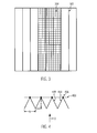
- FIG. 1 shows an exemplary vacuum cleaner filter bag, in which one side is shown open for illustrative purposes. In fact, the page shown here is formed by a weld.
- the exemplary vacuum cleaner filter bag of FIG. 1 included a bag wall of at least partially pleated nonwoven material.
- the at least partially pleated nonwoven material comprises a plurality, in particular more than two, folds 101.
- the folds 101 are in particular standing folds.
- the exemplary vacuum cleaner filter bag of FIG. 1 also comprises an inflow opening 102, through which air to be cleaned can flow into the vacuum cleaner filter bag, and a holding plate 103, which serves to fix the vacuum cleaner filter bag in a chamber of a vacuum cleaner, and has a through hole in the region of the inflow opening 102.
- the pleats 101 of the partially pleated nonwoven material are in the exemplary vacuum cleaner filter bag FIG. 1 formed along the entire length of the vacuum cleaner filter bag.
- the vacuum cleaner filter bag may have a longitudinal side and a broad side.
- the pleats 101 may extend along the longitudinal side or along the broad side, in particular along the entire longitudinal side or broad side.
- a portion 104 of the bag wall is free from wrinkles.
- wrinkles of the at least partially pleated nonwoven material may also be on the entire bag wall.
- the bag wall may in particular comprise two or more filter layers, wherein at least one layer comprises an at least partially pleated nonwoven material.
- FIG. 2 shows a plan view of an inside of a bag wall of an exemplary vacuum cleaner filter bag.
- the pleats 201 of the at least partially pleated nonwoven material are connected together in this example by a fixing device in the form of a plurality of strips of material 205.
- the pleats 201 are held by the strips of material 205 at a predetermined distance from each other.
- the fold width of the folds 201 is fixed by the material strips 205.
- the material strips 205 are at connection points 206 with the folds 201, in particular with an edge of the folds 201, connected, for example glued or welded.
- the material strips 205 may, for example, have a width of 0.5 cm to 4 cm, in particular from 1 cm to 3 cm, for example 2 cm.
- the material strips 205 may comprise a nonwoven material.
- the nonwoven material may in particular comprise extrusion nonwoven fabric, for example a filament spunbonded nonwoven, and / or a carded or airlaid nonwoven fabric.
- the strips of material 205 may also comprise a laminate of a plurality of nonwoven fabrics, in particular a filament spunbonded nonwoven laminate - melt spun microfiber spunbond nonwoven - filament spunbond web.
- the basis weight of the material strips 205 may be less than 200 g / m 2 , in particular between 10 g / m 2 and 30 g / m 2 .
- connection points 206 may be formed such that the connection dissolves during operation of the vacuum cleaner filter bag. By the at least partially dissolved strips of material 205, the flow behavior of the air flowing into the bag can be influenced.
- the material strips 205 may also have a predetermined stretching behavior. Thus, a predetermined expansion of the bag can be achieved during operation.
- the material strips 205 may also have an elasticity, so that the expansion of the bag after operation, ie after switching off the vacuum cleaner, is reduced again by elastic restoring forces. This also allows dust to be carried from the bag wall to the interior of the vacuum cleaner filter bag.
- the fixing element can also be designed as a full-surface material strip.
- the fixing element can have a high air permeability, in particular more than 5000 l / (m 2 s).
- the fixing element may also comprise an air-permeable paper, fabric and / or a film.
- the fixing device can also be perforated and / or slotted.
- FIG. 3 shows a plan view of an inside of a bag wall of another exemplary vacuum cleaner filter bag.
- the fixing device is formed in the form of a net 307 which connects the folds 301 of the pleated nonwoven material in a partial area of the surface. In other areas of the surface, the pleats of the pleated nonwoven material are not connected by the fixing device.
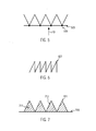
- FIG. 4 shows a cross section through a portion of the bag wall of an exemplary vacuum cleaner filter bag, wherein the cross section is perpendicular to the course of the folds of the pleated nonwoven material.
- FIG. 4 a plurality of pleats of the at least partially pleated nonwoven material of a bag wall of an exemplary vacuum cleaner filter bag interconnected by a fixing device 405.
- the fixing device 405 is connected at connection points 406 to the fold backs of the folds.
- the arrow 410 indicates the direction of flow of the bag wall with the air to be cleaned.
- the fixing device 405 is thus arranged downstream of the at least partially pleated nonwoven material.
- FIG. 4 also shows a pleat leg 409 of a first pleat and a pleat leg 408 of a second pleat that directly or immediately adjoin one another.
- FIG. 4 also illustrates the fold width b and the fold height h.
- the pleat height h and / or the pleat width b can be between 3 mm and 100 mm, in particular between 5 mm and 15 mm.
- FIG. 5 shows a further cross-section through part of a bag wall of an exemplary vacuum cleaner filter bag.
- a plurality of folds 501 are shown, and a fixing device 505 disposed upstream of the inflow direction 510, which are connected to the folds 501 at connection points 506.
- FIG. 6 shows a cross section through a portion of a bag wall of an exemplary vacuum cleaner filter bag, wherein the folds 601 have different lengths of pleat legs in cross section.
- the cavities formed between the folds and the fixing device can be filled with fibers, in particular electrostatically charged fibers, and / or with absorbents.
- fibers in particular electrostatically charged fibers, and / or with absorbents.
- absorbents for example, coated fibers, activated carbon and / or porous polymers can be used as absorbents.
- FIG. 7 shows a cross section of a portion of such a bag wall.
- a plurality of pleats 701 are shown and a fixing device 705 connected thereto.
- Fibers 711 and / or activated carbon 712 are arranged in the cavities between the pleat legs and the fixing device 705.
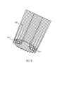
- FIG. 8 shows an exemplary vacuum cleaner filter bag, in particular in a plan view of an outside of the vacuum cleaner filter bag.
- the bag wall includes a plurality of pleats 801.
- the vacuum cleaner filter bag also includes two side pleats 813 and 814, with the side pleats 813 and 814 also including at least partially pleated nonwoven material.
- folds 801 of the at least partially pleated nonwoven material are arranged on the fold legs of the side folds 813 and 814, respectively.
- the gussets 813 and 814 may be partially or completely unfoldable.
- the area available for filtration can be increased for given dimensions of the vacuum cleaner filter bag. This leads to a high separation efficiency with low initial pressure loss. This is accompanied by a lower media passage speed, which increases the separation efficiency, in particular by electrostatically charged fibers of the bag wall.
- FIG. 9 serves as an illustration and shows a diagram showing the volume flow through the bag wall of vacuum cleaner filter bags as a function of the dust load in grams.
- the bag wall consists in each case of a laminate of filament spunbonded nonwoven (spunbonded nonwoven) and meltblown nonwoven fabric. The corresponding measurements were carried out with a vacuum cleaner of the model "Miele S 5210".
- Example 1 Corresponds to a bag wall according to the prior art, ie without an at least partially pleated nonwoven material.
- the bag dimensions are (L x B) 300 mm x 320 mm.
- the SMMS consists of spunbonded nonwoven 35 g / m 2 , 2 x 20 g / m 2 meltblown nonwoven fabric and spunbonded 17 g / m 2 .
- Example 2 Corresponds to a bag wall comprising a fully pleated nonwoven material.
- the fold height is 12 mm.
- the bag dimensions (L x B) were 300 x 630 mm (unfolded).
- the SMMS consists of spunbonded nonwoven 35 g / m 2 , 2 x 20 g / m 2 meltblown nonwoven fabric and spunbonded 17 g / m 2 .
- Example 3 Corresponds to a bag wall according to the invention comprising a completely pleated nonwoven material and a fixing device in the form of a net formed all over with a mesh size of 5 mm x 5 mm.
- the fold height is 12 mm.
- the bag dimensions (L x B) were 300 x 630 mm (unfolded).
- the SMMS consists of spunbonded nonwoven 35 g / m 2 , 2 x 20 g / m 2 meltblown nonwoven fabric and spunbonded 17 g / m 2 .
- Example 4 Corresponds to a bag wall according to the invention comprising a completely pleated nonwoven material and a fixing device in the form of several spaced nonwoven strips (width 20 mm each). The fold height is 12 mm.
- the bag dimensions (L x B) were 300 x 630 mm (unfolded).
- the SMMS consists of spunbonded nonwoven 35 g / m 2 , 2 x 20 g / m 2 meltblown nonwoven fabric and spunbonded 17 g / m 2 .
- Example 5 Corresponds to a bag wall according to the invention comprising a completely pleated nonwoven material and a fixing device in the form of several spaced nonwoven strips (width each 20 mm). The fold height is 12 mm.
- the bag dimensions (L x B) were 300 x 630 mm (unfolded).
- the SMMS consists of spunbonded nonwoven 35 g / m 2 , 2 x 20 g / m 2 meltblown nonwoven fabric and spunbonded 17 g / m 2 .
- the vacuum cleaner filter bag according to Example 5 additionally comprises at least one element for flow deflection or flow distribution (14 strips each 11 mm wide, laminate with a basis weight of 110 g / m 2 ) in the vacuum cleaner filter bag.
- the vacuum cleaner filter bags with a bag wall comprising an at least partially pleated nonwoven material, even at high dust loads a larger volume flow, as a vacuum cleaner filter bag with a bag wall without pleated nonwoven material.
- Table 1 shows averages (from 5 measurements) of the measured pressure loss and the measured penetration of a prior art vacuum cleaner filter bag material with a bag wall of a filament spunbonded nonwoven laminate (basis weight 35 g / m 2 ), 2 layers of meltblown nonwoven fabric (20 basis weight each) g / m 2 ) and a filament spunbonded nonwoven fabric (basis weight 17 g / m 2 ).
- Table 1. Measured with TSI 8130 Flow rate [l / min] Pressure drop ⁇ P [mm H 2 O] Penetration [%] means 86.92 14.46 32.2
- Table 2 shows mean values (from 5 measurements) of the measured pressure loss and the measured penetration of a vacuum cleaner filter bag with a bag wall of a pleated laminate of a filament spunbonded nonwoven (basis weight 35 g / m 2 ), 2 layers of meltblown nonwoven fabric (basis weight 20 g / m 2 each) and a filament spunbonded nonwoven fabric (basis weight 17 g / m 2 ).
- Table 2. Measured with TSI 8130 Flow rate [l / min] Pressure drop ⁇ P [mm H 2 O] Penetration [%] means 42,98 6.86 18.72
- Table 3 are averages (from 2 measurements) of the measured pressure loss and measured penetration of a prior art vacuum cleaner filter bag with a HEPA laminate filament spunbonded pouch (basis weight 35 g / m 2 ), 4 layers of meltblown nonwoven fabric (19 basis weight per unit area) g / m 2 ) and a filament spunbonded nonwoven fabric (basis weight 17 g / m 2 ).
- Table 3 Measured with TSI 8130 Flow rate [l / min] Pressure drop ⁇ P [mm H 2 O] Penetration [%] means 86.1 32.05 0,025
- Table 4 shows average values (from 2 measurements) of the measured pressure loss and the measured penetration of a vacuum cleaner filter bag with a pleated bag wall of a HEPA laminate of a filament spunbonded nonwoven (basis weight 35 g / m 2 ), 4 layers of meltblown nonwoven (basis weight 19 g / m 2 ) and a filament spunbonded nonwoven fabric (basis weight 17 g / m 2 ).
- Table 4. Measured with TSI 8130 Flow rate [l / min] Pressure drop ⁇ P [mm H 2 O] Penetration [%] means 43.05 15.5 0,004
- vacuum cleaner filter bag may be formed in different geometries and / or sizes.
Abstract
Description
Die Erfindung betrifft einen Staubsaugerfilterbeutel mit einer Beutelwand aus Filtermaterial, die eine Durchgangsöffnung aufweist, durch die zu reinigende Luft in den Staubsaugerfilterbeutel einströmen kann.The invention relates to a vacuum cleaner filter bag with a bag wall made of filter material, which has a passage opening through which air to be purified can flow into the vacuum cleaner filter bag.
Staubsaugerfilterbeutel werden heute vorwiegend aus Vliesstoffen gefertigt. Aufgrund ihrer hervorragenden Staubspeicherfähigkeit haben Staubsaugerfilterbeutel aus Vliesstoffen Filterbeutel aus Papier praktisch verdrängt. Die Herstellung der Filterbeutel aus Vliesstoffen unterscheidet sich grundlegend von der Herstellung von Papierbeuteln. Gebräuchlich sind rechteckige Flachbeutel, die aus einer oberen und einer unter Lage gebildet werden, die am Rand umlaufend verschweißt sind. Derartige Filterbeutel sind beispielsweise aus der
Aus der
Die positiven Eigenschaften von Staubsaugerfilterbeuteln aus Vliesstoffen können teilweise aufgrund unzureichender Passform nicht genutzt werden. Daher wurden aufwendige Beutelgeometrien entwickelt, um den im Staubsauger zur Verfügung stehenden Bauraum optimal zu nutzen.The positive characteristics of nonwoven vacuum cleaner filter bags may not be fully utilized due to insufficient fit. Therefore, elaborate bag geometries have been developed in order to optimally use the space available in the vacuum cleaner.
Um ein größeres Füllvolumen im Vergleich zu einem reinen Flachbeutel zu erhalten, werden beispielsweise Flachbeutel mit umlaufender Schweißnaht und ausstülpbaren Seitenfalten verwendet. Derartige Filterbeutel sind beispielsweise aus der
Neben Flachbeuteln finden gelegentlich auch Blockbodenbeutel, auch Klotzbodenbeutel genannt, Verwendung. Blockbodenbeutel aus Vliesstoff sind aufwendig in der Herstellung. Blockbodenbeutel sind beispielsweise aus der
Um die Staubspeicherfähigkeit der Staubsaugerfilterbeutel zu erhöhen, wurden unterschiedliche Lösungen vorgeschlagen.In order to increase the dust storage capacity of the vacuum cleaner filter bags, various solutions have been proposed.
Eine Vorfiltration durch lose Fasern wird beispielsweise in der
Die
Die
Die
Filtermaterialien, die zur Vergrößerung der wirksamen Oberfläche gefaltet verwendet werden, wobei die Falten fixiert/stabilisiert werden, sind bekannt. So offenbart beispielsweise die
Trotz der oben genannten Verbesserungen sind einige Probleme von Staubsaugerfilterbeuteln noch nicht befriedigend gelöst. Der Volumenstrom, der durch den Staubsauger gefördert wird, nimmt bei steigendem Füllgrad des Filterbeutels kontinuierlich ab. Die Staubaufnahme, also die Reinigungswirkung, eines Staubsaugers ist mit einem teilgefüllten Staubsaugerbeutel also geringer als mit einem leeren Beutel. Diese Abnahme der Saugleistung ist bei Filterbeuteln mit einem hohen Abscheidgrad besonders stark.Despite the above improvements, some problems of vacuum cleaner filter bags have not yet been satisfactorily solved. The volume flow, which is conveyed through the vacuum cleaner, decreases continuously with increasing filling level of the filter bag. The dust, so the cleaning effect of a vacuum cleaner is so low with a partially filled vacuum cleaner bag as with an empty bag. This decrease in suction power is particularly strong in filter bags with a high degree of separation.
Aufgabe der vorliegenden Erfindung ist es, einen Staubsaugerfilterbeutel bereitzustellen, der eine hohe Staubspeicherfähigkeit aufweist.The object of the present invention is to provide a vacuum cleaner filter bag having a high dust holding ability.
Die Erfindung stellt einen Staubsaugerfilterbeutel bereit mit einer Beutelwand aus Filtermaterial, die eine Durchgangsöffnung aufweist, durch die zu reinigende Luft in den Staubsaugerfilterbeutel einströmen kann, wobei die Beutelwand ein wenigstens teilweise plissiertes Vliesstoffmaterial umfasst. Die Falten des plissierten Vliesstoffmaterials sind wenigstens teilweise mittels einer Fixiervorrichtung miteinander verbunden. Durch die Fixiervorrichtung können die Falten des wenigstens teilsweise plissierten Vliesstoffmaterials in einem vorherbestimmten Abstand zueinander gehalten werden. Die Fixiervorrichtung ist zudem wenigstens teilweise mit den Falten des wenigstens teilweise plissierten Vliesstoffmaterials verklebt und/oder verschweißt.The invention provides a vacuum cleaner filter bag having a bag wall of filter material having a through opening through which air to be cleaned can flow into the vacuum cleaner filter bag, wherein the bag wall comprises an at least partially pleated nonwoven material. The pleats of the pleated nonwoven material are at least partially interconnected by means of a fixing device. By the fixing device, the folds of the at least partially pleated nonwoven material can be kept at a predetermined distance from each other. The fixing device is also at least partially bonded and / or welded to the folds of the at least partially pleated nonwoven material.
Durch das wenigstens teilweise plissierte Vliesstoffmaterial kann die zur Filtration der zu reinigenden Luft zur Verfügung stehende Fläche vergrößert werden, wodurch eine erhöhte Staubspeicherfähigkeit erreicht wird.By the at least partially pleated nonwoven material, the area available for filtration of the air to be purified can be increased, whereby an increased dust storage capacity is achieved.
Das plissierte Vliesstoffmaterial weist mehrere, insbesondere zwei oder mehr, vorherbestimmte Falten auf. Mit anderen Worten entspricht das wenigstens teilweise plissierte Vliesstoffmaterial einem wenigstens teilweise gefältelten oder gewellten Vliesstoffmaterial.The pleated nonwoven material has a plurality, in particular two or more, predetermined folds. In other words, the at least partially pleated nonwoven material corresponds to an at least partially crimped or corrugated nonwoven material.
Ein Faltenschenkel einer ersten Falte des wenigstens teilweise plissierten Vliesstoffmaterials kann direkt an einen Faltenschenkel einer zweiten Falte des wenigstens teilweise plissierten Vliesstoffmaterials angrenzen. Mit anderen Worten können die Falten des wenigstens teilweise plissierten Vliesstoffmaterials unmittelbar aneinander anschließen oder angrenzen beziehungsweise sich berühren.A pleat leg of a first pleat of the at least partially pleated nonwoven material may directly abut a pleat leg of a second pleat of the at least partially pleated nonwoven material. In other words, the folds of the at least partially pleated nonwoven material can directly adjoin or adjoin one another or touch each other.
Die Falten des plissierten Vliesstoffmaterials können insbesondere zickzackförmig sein. Mit anderen Worten kann eine erste Falte des plissierten Vliesstoffmaterials einer Spiegelung einer zweiten Falte entlang einer senkrechten Ebene zwischen den beiden Falten entsprechen.The pleats of the pleated nonwoven material may in particular be zigzag. In other words, a first fold of the pleated nonwoven material may correspond to a mirroring of a second fold along a vertical plane between the two folds.
Das wenigstens teilweise plissierte Filtermaterial kann insbesondere mehr als 5, 10, 20, 30, 40 oder 50 unmittelbar aneinandergrenzende Falten aufweisen.The at least partially pleated filter material may in particular have more than 5, 10, 20, 30, 40 or 50 directly adjacent folds.
Eine oder mehrere der Falten können liegend oder stehend ausgebildet sein. Unter liegenden Falten sind Falten zu verstehen, deren Faltenschenkel im Wesentlichen parallel zu einer Außenfläche der Beutelwand angeordnet sind. Unter stehenden Falten sind Falten zu verstehen, deren Faltenschenkel mit einer Außenfläche der Beutelwand einen Winkel größer 0° und kleiner 180°, insbesondere größer 20° oder größer 45°, einschließen.One or more of the folds may be lying or standing. Underlying wrinkles are to be understood as wrinkles whose fold limbs are arranged substantially parallel to an outer surface of the pouch wall. Under standing wrinkles are to be understood as wrinkles whose pleat legs with an outer surface of the bag wall at an angle greater than 0 ° and less than 180 °, in particular greater than 20 ° or greater than 45 ° include.
Das wenigstens teilweise plissierte Vliesstoffmaterial kann eine oder mehrere Schichten aus Vliesstoffmaterial umfassen.The at least partially pleated nonwoven material may comprise one or more layers of nonwoven material.
Die Beutelwand des Staubsaugerfilterbeutels kann eine oder mehrere Schichten aus Vliesstoffmaterial umfassen, insbesondere wobei eine oder mehrere Schichten der Beutelwand ein wenigstens teilweise plissiertes Vliesstoffmaterial umfassen oder aus einem wenigstens teilweise plissierten Vliesstoffmaterial bestehen. Die Beutelwand kann auch aus einer oder mehreren Schichten aus wenigstens teilweise plissiertem Vliesstoffmaterial bestehen.The bag wall of the vacuum cleaner filter bag may comprise one or more layers of nonwoven material, in particular wherein one or more layers of the bag wall comprise an at least partially pleated nonwoven material or consist of an at least partially pleated nonwoven material. The bag wall may also consist of one or more layers of at least partially pleated nonwoven material.
Eine Beutelwand umfassend wenigstens teilweise plissiertes Vliesstoffmaterial ist von einer Beutelwand mit einer oder zwei Seitenfalten zu unterscheiden. Während "plissiert" eine Eigenschaft des Vliesstoffmaterials der Beutelwand ist, ist eine Seitenfalte ein Merkmal der Beutelwand, das bei der Formgebung des Beutels hergestellt wird.A bag wall comprising at least partially pleated nonwoven material is to be distinguished from a bag wall having one or two side pleats. While "pleated" is a characteristic of the nonwoven material of the pouch wall, a gusset is a feature of the pouch wall that is fabricated during the molding of the pouch.
Eine Beutelwand umfassend wenigstens teilweise plissiertes Vliesstoffmaterial ist auch von einer Beutelwand umfassend ein gekrepptes oder profiliertes Vliesstoffmaterial zu unterscheiden. Im Gegensatz zum Kreppen eines Vliesstoffmaterials oder einer Profilierung des Vliesstoffmaterials durch Verprägen werden die Materialeigenschaften des Vliesstoffmaterials als solches durch das Plissieren nicht verändert. Durch das Plissieren des Vliesstoffmaterials wird lediglich die Anordnung des Vliesstoffmaterials verändert.A bag wall comprising at least partially pleated nonwoven material is also to be distinguished from a bag wall comprising a creped or profiled nonwoven material. In contrast to creping a nonwoven material or profiling the nonwoven material by embossing, the material properties of the nonwoven material per se are not altered by pleating. By pleating the nonwoven material, only the arrangement of the nonwoven material is changed.
Im Gegensatz zum Kreppen werden beim Plissieren außerdem regelmäßige, insbesondere vorherbestimmte, Falten gebildet.In contrast to creping, pleats also form regular, in particular predetermined, wrinkles.
Die Falten des wenigstens teilweise plissierten Vliesstoffmaterials können in einem vorherbestimmten Bereich der Beutelwand, beispielsweise über die gesamte oder über Teilbereiche der zur Filtration der zu reinigenden Luft zur Verfügung stehenden Fläche der Beutelwand, angeordnet sein.The pleats of the at least partially pleated nonwoven material may be arranged in a predetermined area of the bag wall, for example over all or part of the area of the bag wall available for filtration of the air to be cleaned.
Die Beutelwand kann auch ein vollständig plissiertes Vliesstoffmaterial umfassen oder aus einem vollständig plissierten Vliesstoffmaterial bestehen.The bag wall may also comprise a fully pleated nonwoven material or may consist of a fully pleated nonwoven material.
Falten des wenigstens teilweise plissierten Vliesstoffmaterials können sich über die gesamte Länge oder Breite des Staubsaugerfilterbeutels erstrecken. Mit anderen Worten können Falten des wenigstens teilweise plissierten Vliesstoffmaterials, insbesondere ununterbrochen, von einer ersten durch eine Kante gebildeten Seite des Staubsaugerfilterbeutels zu einer zweiten, der ersten Seite gegenüberliegenden, durch eine Kante gebildeten Seite des Staubsaugerfilterbeutels, verlaufen.Folds of the at least partially pleated nonwoven material may extend the entire length or width of the vacuum cleaner filter bag. In other words, folds of the at least partially pleated nonwoven material, in particular uninterrupted, from a first side formed by an edge of the vacuum cleaner filter bag to a second, the first side opposite, formed by an edge side of the vacuum cleaner filter bag, extend.
Der Staubsaugerfilterbeutel kann als Flachbeutel ausgebildet sein. In diesem Fall kann die Beutelwand eine erste und eine zweite Filtermateriallage umfassen, die durch eine umlaufende Schweißnaht miteinander verbunden sind, wobei die erste und/oder zweite Filtermateriallage das wenigstens teilweise plissierte Vliesstoffmaterial umfassen können.The vacuum cleaner filter bag may be formed as a flat bag. In this case, the bag wall may include first and second filter material layers joined together by a circumferential weld, wherein the first and / or second filter material layers may comprise the at least partially pleated nonwoven material.
Die erste und/oder zweite Filtermateriallage können jeweils eine oder mehrere Schichten aus Vliesstoffmaterial umfassen.The first and / or second filter material layers may each comprise one or more layers of nonwoven material.
Alternativ kann der Staubsaugerfilterbeutel auch als Schlauchbeutel ausgebildet sein. Dabei kann die Beutelwand aus einer Filtermateriallage gefertigt werden, wobei zwei, insbesondere gegenüberliegende, Ränder der Filtermateriallage verbunden werden, wodurch ein Schlauch gebildet wird. Durch Verschließen der offenen Enden des Schlauches durch Querschweißnähte wird ein Schlauchbeutel erhalten. Das Verbinden der Ränder bei der Bildung des Schlauches und/oder das Verschließen der offenen Enden des Schlauches kann durch Ultraschallverschweißen und/oder durch thermisches Verschweißen und/oder durch Verkleben geschehen.Alternatively, the vacuum cleaner filter bag can also be designed as a tubular bag. In this case, the bag wall can be made of a filter material layer, wherein two, in particular opposite, edges of the filter material layer are connected, whereby a hose is formed. By closing the open ends of the tube by transverse welds a tubular bag is obtained. The joining of the edges in the formation of the tube and / or the closing of the open ends of the tube can be done by ultrasonic welding and / or by thermal welding and / or by gluing.
Die Filtermateriallage kann eine oder mehrere Schichten aus Vliesstoffmaterial umfassen.The filter material layer may comprise one or more layers of nonwoven material.
Die Falten des wenigstens teilweise plissierten Vliesstoffmaterials können eine Faltenhöhe zwischen 3 mm und 100 mm, insbesondere zwischen 3 mm und 50 mm, insbesondere zwischen 5 mm und 15 mm, aufweisen. Die Faltenhöhe kann auch größer als 100 mm sein. Dies kann insbesondere bei großen (Volumen von mehr als 10 Liter), insbesondere gewerblich genutzten, Staubsaugerfilterbeuteln der Fall sein.The pleats of the at least partially pleated nonwoven material may have a pleat height between 3 mm and 100 mm, in particular between 3 mm and 50 mm, in particular between 5 mm and 15 mm. The pleat height can also be greater than 100 mm. This may be the case in particular for large (volume of more than 10 liters), in particular commercially used, vacuum cleaner filter bags.
Die Falten des plissierten Vliesstoffmaterials können eine Faltenbreite zwischen 3 mm und 100 mm, insbesondere zwischen 3 mm und 50 mm, insbesondere zwischen 5 mm und 15 mm, aufweisen. Die Faltenbreite kann auch größer als 100 mm sein. Dies kann insbesondere bei großen (Volumen von mehr als 10 Liter), insbesondere gewerblich genutzten, Staubsaugerfilterbeuteln der Fall sein.The pleats of the pleated nonwoven material may have a pleat width between 3 mm and 100 mm, in particular between 3 mm and 50 mm, in particular between 5 mm and 15 mm. The fold width can also be greater than 100 mm. This may be the case in particular for large (volume of more than 10 liters), in particular commercially used, vacuum cleaner filter bags.
Wenigstens zwei Falten des plissierten Vliesstoffmaterials können eine voneinander unterschiedliche Faltenhöhe und/oder Faltenbreite aufweisen. Alternativ können alle Falten des wenigstens teilweise plissierten Vliesstoffmaterials gleiche Faltenhöhen und/oder Faltenbreiten aufweisen.At least two pleats of the pleated nonwoven material may have a different pleat height and / or pleat width. Alternatively, all pleats of the at least partially pleated nonwoven material may have equal pleat heights and / or pleat widths.
Der Staubsaugerfilterbeutel kann außerdem wenigstens eine Seitenfalte umfassen, insbesondere wobei das plissierte Vliesstoffmaterial in der wenigstens einen Seitenfalte angeordnet ist. Es können also eine oder mehrere Falten des wenigstens teilweise plissierten Vliesstoffmaterials an wenigstens einem Faltenschenkel der wenigstens einen Seitenfalte angeordnet sein.The vacuum cleaner filter bag may further comprise at least one gusset, in particular wherein the pleated nonwoven material is disposed in the at least one gusset. Thus, one or more folds of the at least partially pleated nonwoven material can be arranged on at least one pleat leg of the at least one gusset.
Wenigstens zwei Falten des plissierten Vliesstoffmaterials können eine voneinander unterschiedliche Faltenform aufweisen.At least two pleats of the pleated nonwoven material may have a different wrinkle shape from each other.
Die Falten des wenigstens teilweise plissierten Vliesstoffmaterials können jeweils einen ersten und einen zweiten Faltenschenkel umfassen. Der erste und zweite Faltenschenkel können gleich lang oder unterschiedlich lang ausgebildet sein. Eine Kante, an der die Faltenschenkel zusammentreffen, kann durch eine Falzlinie gebildet werden.The pleats of the at least partially pleated nonwoven material may each comprise a first and a second pleat leg. The first and second pleat legs may be the same length or different lengths. An edge at which the pleat legs meet can be formed by a fold line.
Als Materialien für die Beutelwand, insbesondere für das wenigstens teilweise plissierte Vliesstoffmaterial, kommen prinzipiell alle für die Herstellung von Staubsaugerfilterbeuteln bekannten Materialen in Betracht.Suitable materials for the bag wall, in particular for the at least partially pleated nonwoven material, are in principle all materials known for the production of vacuum cleaner filter bags.
Als Vliesstoffmaterial kann ein trocken- oder nassgelegter Vliesstoff oder ein Extrusionsvliesstoff, insbesondere ein schmelzgesponnener Mikrofaserspinnvliesstoff (Meltblownvliesstoff) oder Filamentspinnvliesstoff (Spunbond) verwendet werden. Die Abgrenzung zwischen nassgelegtem Vliesstoffen beziehungsweise Nonwovens und herkömmlichen nassgelegtem Papier erfolgt gemäß der oben genannten Definition, wie sie auch von der International Association Serving the Nonwovens and related Industries (EDANA) verwendet wird. Ein herkömmliches (Filter-) Papier ist also kein Vliesstoff.As the nonwoven fabric material, a dry-laid or wet-laid nonwoven fabric or an extrusion nonwoven fabric, particularly a melt-spun microfiber spunbond fabric (meltblown nonwoven fabric) or spunbonded nonwoven fabric, may be used. The distinction between wet laid nonwovens and conventional wet laid paper is made according to the definition above, as used by the International Association Serving the Nonwoven and Related Industries (EDANA). A conventional (filter) paper is therefore not a nonwoven.
Der Vliesstoff kann Stapelfasern oder Endlosfasern umfassen. Fertigungstechnisch können auch mehrere Schichten an Stapelfasern oder Endlosfasern vorgesehen werden, die zu genau einer Schicht Vliesstoff verfestigt werden.The nonwoven fabric may comprise staple fibers or continuous fibers. Manufacturing technology can also provide several layers of staple fibers or continuous fibers, which are solidified to exactly one layer of nonwoven fabric.
Beispielsweise kann die Beutelwand, insbesondere das wenigstens teilweise plissierte Vliesstoffmaterial, ein Laminat aus Filamentspinnvliesstoff, Meltblownvliesstoff und Filamentspinnvliesstoff (SMS) umfassen. Dieses Laminat kann mittels eines Heißklebers laminiert oder kalandriert sein. Die Schicht aus Meltblownvliesstoff kann gekreppt sein.For example, the bag wall, particularly the at least partially pleated nonwoven material, may comprise a laminate of spunbonded nonwoven fabric, meltblown nonwoven fabric, and filament nonwoven web (SMS). This laminate may be laminated or calendered by means of a hot melt adhesive. The layer of meltblown nonwoven fabric may be creped.
Der Begriff Vliesstoff ("Nonwoven") wird gemäß der Definition nach ISO-Standard ISO 9092: 1988 beziehungsweise CEN-Standard EN29092 verwendet. Insbesondere sind die Begriffe Faservlies oder Vlies und Vliesstoff auf dem Gebiet der Herstellung von Vliesstoffen wie folgt gegeneinander abgegrenzt und auch im Sinne der vorliegenden Erfindung so zu verstehen. Zur Herstellung eines Vliesstoffes werden Fasern und/oder Filamente verwendet. Die lockeren oder losen und noch unverbundenen Fasern und/oder Filamente werden als Vlies oder Faservlies (Web) bezeichnet. Durch einen sogenannten Vliesbindeschritt entsteht aus einem derartigen Faservlies schließlich ein Vliesstoff, der eine ausreichende Festigkeit aufweist, um zum Beispiel zu Rollen aufgewickelt zu werden. Mit anderen Worten wird ein Vliesstoff durch die Verfestigung selbstragend ausgebildet. (Details zur Verwendung der hierin beschriebenen Definitionen und/oder Verfahren lassen sich auch im Standardwerk "
Das wenigstens teilweise plissierte Vliesstoffmaterial kann ein Flächengewicht von unter 250 g/m2, insbesondere unter 200 g/m2, insbesondere zwischen 25 g/m2 und 150 g/m2, aufweisen.The at least partially pleated nonwoven material may have a weight per unit area of less than 250 g / m 2 , in particular less than 200 g / m 2 , in particular between 25 g / m 2 and 150 g / m 2 .
Das wenigstens teilweise plissierte Vliesstoffmaterial kann aber auch ein Flächengewicht von über 250 g/m2 aufweisen. Insbesondere für gewerbliche Staubsaugerfilterbeutel kann dies, je nach mechanischer Anforderung, der Fall sein.However, the at least partially pleated nonwoven material may also have a basis weight of over 250 g / m 2 . This may be the case, in particular for commercial vacuum cleaner filter bags, depending on the mechanical requirements.
Die Fixiervorrichtung kann anströmseitig oder abströmseitig des wenigstens teilweise plissierten Vliesstoffmaterials angeordnet sein. Anströmseitig bedeutet hier dem Inneren des Staubsaugerfilterbeutels zugewandt, während abströmseitig dem Äußeren des Staubsaugerfilterbeutels zugewandt bedeutet.The fixing device can be arranged on the inflow side or outflow side of the at least partially pleated nonwoven material. On the inflow side here means facing the interior of the vacuum cleaner filter bag, while the downstream side faces the exterior of the vacuum cleaner filter bag.
Insbesondere kann die Fixiervorrichtung an Stellen angeklebt und/oder angeschweißt sein, an denen Faltenschenkel zweier unterschiedlicher Falten des wenigstens teilweise plissierten Vliesstoffmaterials aneinandergrenzen. Alternativ oder zusätzlich kann die Fixiervorrichtung am Faltenrücken der Falten angeklebt und/oder angeschweißt sein. Als Faltenrücken kann die Kante einer Falte bezeichnet werden, an der die beiden Faltenschenkel der Falte aneinandergrenzen bzw. sich berühren.In particular, the fixing device can be glued and / or welded at locations where adjoining fold limbs of two different folds of the at least partially pleated nonwoven material. Alternatively or additionally, the fixing device may be glued and / or welded to the fold back of the folds. The pleat back can be the edge of a fold at which the two pleat legs of the pleat adjoin one another or touch each other.
Es können auch zwei oder mehr Falten des wenigstens teilweise plissierten Vliesstoffmaterials durch die Fixiervorrichtung miteinander verbunden sein, während zwei oder mehr Falten des plissierten Vliesstoffmaterials nicht durch die Fixiervorrichtung miteinander verbunden sind.Also, two or more pleats of the at least partially pleated nonwoven fabric may be bonded together by the fixing device while two or more pleats of the pleated nonwoven fabric are not bonded together by the fixing device.
Alternativ oder zusätzlich kann die Fixiervorrichtung derart mit einer oder mehreren Falten des wenigstens teilweise plissierten Vliesstoffmaterials verklebt und/oder verschweißt sein, dass sich die Verbindung im Betrieb des Staubsaugerfilterbeutels löst. Damit kann durch die sich wenigstens teilweise lösende Fixiervorrichtung der Luftstrom innerhalb des Staubsaugerfilterbeutels beeinflusst werden. Mit anderen Worten können Teile der Fixiervorrichtung im Betrieb des Staubsaugerfilterbeutels als Luftverteiler dienen.Alternatively or additionally, the fixing device can be glued and / or welded to one or more folds of the at least partially pleated nonwoven material in such a way that the connection dissolves during operation of the vacuum cleaner filter bag. This can be influenced by the at least partially releasing fixing the air flow within the vacuum cleaner filter bag. In other words, parts of the fixing device can serve as an air distributor during operation of the vacuum cleaner filter bag.
Alternativ oder zusätzlich kann der Staubsaugerfilterbeutel wenigstens ein Element zur Strömungsumlenkung oder Strömungsverteilung im Staubsaugerfilterbeutel umfassen. Ein derartiges Element ist beispielsweise aus der
Die Fixiervorrichtung kann derart ausgebildet sein, dass es die Faltenbreite der Falten, die durch das Fixierelement miteinander verbunden werden, im Betrieb des Staubsaugerfilterbeutels konstant hält.The fixing device may be designed such that it keeps the fold width of the folds which are connected to one another by the fixing element constant during operation of the vacuum cleaner filter bag.
Alternativ oder zusätzlich kann die Fixiervorrichtung ein vorherbestimmtes Dehnungsverhalten aufweisen. Mit anderen Worten kann die Fixiervorrichtung derart ausgebildet sein, dass die Faltenbreite der durch die Fixiervorrichtung verbundenen Falten im Betrieb des Beutels durch Dehnung der Fixiervorrichtung vergrößert werden können. Die Fixiervorrichtung kann eine Elastizität aufweisen, die derart gewählt ist, dass die Fixiervorrichtung nach dem Betrieb des Staubsaugerfilterbeutels, also nach Abschalten des Staubsaugers, wieder in ihre ursprüngliche Form zurückkehrt.Alternatively or additionally, the fixing device may have a predetermined expansion behavior. In other words, the fixing device can be designed such that the fold width of the folds connected by the fixing device can be increased during operation of the bag by stretching the fixing device. The fixing device may have an elasticity which is selected such that the fixing device returns to its original shape after operation of the vacuum cleaner filter bag, that is, after switching off the vacuum cleaner.
Die Fixiervorrichtung kann auch teilweise, insbesondere in Teilbereichen, durch dehnbare Materialstreifen und teilweise, insbesondere in anderen Teilbereichen, durch nicht dehnbare Materialstreifen gebildet werden.The fixing device may also be partially, in particular in sub-areas, formed by stretchable strips of material and partially, in particular in other sub-areas, by non-stretchable strips of material.
Die Fixiervorrichtung kann wenigstens einen Materialstreifen, insbesondere einen Vliesstoffmaterialstreifen, umfassen. Mehrere Materialstreifen können beabstandet zueinander angeordnet sein oder direkt aneinander angrenzen.The fixing device may comprise at least one strip of material, in particular a non-woven material strip. Several strips of material may be spaced apart from each other or directly adjacent to each other.
Mehrere Materialstreifen können quer, insbesondere senkrecht oder unter einem vorherbestimmten Winkel, zur Längsrichtung der Falten verlaufen. Der vorherbestimmte Winkel kann größer als 0° und kleiner als 180°, insbesondere größer als 30° und kleiner als 150°, sein.Several strips of material may run transversely, in particular perpendicularly or at a predetermined angle, to the longitudinal direction of the folds. The predetermined angle may be greater than 0 ° and less than 180 °, in particular greater than 30 ° and less than 150 °.
Das Material der Fixiervorrichtung kann eine hohe Luftdurchlässigkeit aufweisen. Wenn das Material der Fixiervorrichtung luftundurchlässig ist, kann die Fixiervorrichtung gelocht und/oder geschlitzt ausgebildet sein.The material of the fixing device may have a high air permeability. If the material of the fixing device is impermeable to air, the fixing device may be perforated and / or slotted.
Die Fixiervorrichtung kann in Form wenigstens eines durchgehenden Klebstoffstreifens ausgebildet sein. Als Klebstoff kann insbesondere ein Schmelzklebstoff (Hotmelt) verwendet werden.The fixing device may be in the form of at least one continuous adhesive strip. As the adhesive, in particular, a hot melt adhesive (hot melt) can be used.
Der wenigstens eine Materialstreifen kann eine Breite von 0,5 cm bis 4 cm, insbesondere von 1 cm bis 3 cm, beispielsweise 2 cm aufweisen. Der wenigstens eine Materialstreifen kann eine Dicke von 0,1 mm bis 10 mm, insbesondere von 0,3 mm bis 4 mm, aufweisen.The at least one strip of material may have a width of 0.5 cm to 4 cm, in particular of 1 cm to 3 cm, for example 2 cm. The at least one strip of material may have a thickness of 0.1 mm to 10 mm, in particular of 0.3 mm to 4 mm.
Die Fixiervorrichtung kann in Form von einem oder zwei Materialstreifen ausgebildet sein, deren Breite und/oder Länge der Breite und/oder Länge der Beutelwand entsprechen. Mit anderen Worten kann die Fixiervorrichtung vollflächig ausgebildet sein.The fixing device may be in the form of one or two strips of material whose width and / or length correspond to the width and / or length of the bag wall. In other words, the fixing device can be formed over the entire surface.
Die Fixiervorrichtung kann ein Vliesstoffmaterial, eine Folie und/oder ein Papier umfassen.The fixing device may comprise a nonwoven material, a film and / or a paper.
Als Vliesstoffmaterial für die Fixiervorrichtung sind beispielsweise Filamentspinnvliesstoffe, kardierte oder Airlaid Vliesstoffe und/oder Laminate aus mehreren Vliesstoffen möglich. Bei Laminaten aus mehreren Vliesstoffen können die unterschiedlichen Vliesstoffschichten einen Gradienten im Porendurchmesser aufweisen.As the nonwoven material for the fixing device, for example, filament spunbonded nonwoven fabrics, carded or airlaid nonwoven fabrics and / or laminates of a plurality of nonwoven fabrics are possible. For laminates of multiple nonwoven fabrics, the different nonwoven fabric layers may have a gradient in pore diameter.
Die Fixiervorrichtung kann auch in Form eines Gewebes oder eines Netzes ausgebildet sein. Insbesondere kann die Fixiervorrichtung in Form eines extrudierten Netzes ausgebildet sein. Die Maschenweite des Netzes kann dabei zwischen 0,5 mm und 10 cm, insbesondere zwischen 3 mm und 6 mm, liegen. Die Form der Löcher des Netzes kann quadratisch oder rechteckig sein. Es können auch ein oder mehrere Löcher des Netzes quadratisch und ein oder mehrere Löcher des Netzes rechteckig sein.The fixing device can also be designed in the form of a fabric or a net. In particular, the fixing device may be in the form of an extruded net. The mesh size of the network can be between 0.5 mm and 10 cm, in particular between 3 mm and 6 mm. The shape of the holes of the net can be square or rectangular. One or more holes of the mesh may be square and one or more holes of the mesh may be rectangular.
Die Fixiervorrichtung kann auch Filamente, Taue und/oder Garne umfassen.The fixing device may also comprise filaments, tows and / or yarns.
Die Fixiervorrichtung kann auch einer Halteplatte des Staubsaugerfilterbeutels entsprechen. Mit anderen Worten können die Falten des wenigstens teilweise plissierten Vliesstoffmaterials wenigstens teilweise mittels der Halteplatte des Staubsaugerfilterbeutels miteinander verbunden sein.The fixing device may also correspond to a holding plate of the vacuum cleaner filter bag. In other words, the pleats of the at least partially pleated nonwoven material may be at least partially interconnected by means of the support plate of the vacuum cleaner filter bag.
Zwei oder mehr Falten des wenigstens teilweise plissierten Vliesstoffmaterials können auch nicht durch eine Fixiervorrichtung miteinander verbunden sein, also jeweils eine veränderliche Faltenbreite aufweisen. Im Betrieb des Stabsaugerfilterbeutels kann sich der Staubsaugerfilterbeutel in Abhängigkeit vom umgebenden Staubsaugergehäuse entfalten. Unverbundene Falten des plissierten Vliesstoffmaterials können sich im Betrieb an das umgebende Gehäuse anpassen. Damit kann eine verbesserte Raumausnutzung erreicht werden.Two or more folds of the at least partially pleated nonwoven material may also not be connected to one another by a fixing device, that is to say in each case have a variable fold width. During operation of the vacuum cleaner filter bag, the vacuum cleaner filter bag may deploy depending on the surrounding vacuum cleaner housing. Unconnected pleats of the pleated nonwoven material may conform to the surrounding housing during operation. Thus, an improved space utilization can be achieved.
Durch eine vorherbestimmte Kombination von einem oder mehreren Bereichen des wenigstens teilweise plissierten Vliesstoffmaterials, in dem die Falten nicht fixiert sind, und einem oder mehreren Bereichen des plissierten Vliesstoffmaterials, in denen die Falten fixiert sind, kann eine Anpassung an die Geometrie eines Bauraums eines Staubsaugers optimiert werden.By a predetermined combination of one or more regions of the at least partially pleated nonwoven material in which the pleats are not fixed, and one or more Regions of the pleated nonwoven material in which the folds are fixed, an adaptation to the geometry of a construction space of a vacuum cleaner can be optimized.
Ein Vliesstoffmaterial des Fixierelements kann ein Flächengewicht von 10 g/m2 bis 30 g/m2 aufweisen.A nonwoven material of the fixing element may have a basis weight of 10 g / m 2 to 30 g / m 2 .
Die Fixiervorrichtung kann auch als Vorfilterschicht ausgeführt sein. Mit anderen Worten kann die Fixiervorrichtung selbst als Filterschicht ausgebildet sein. In diesem Fall kann das Flächengewicht der Fixiervorrichtung kleiner als 100 g/m2 sein. Beispielsweise kann die Fixiervorrichtung einem Laminat aus einem oder mehreren Filamentspinnvliesstoffen und einem oder mehreren schmelzgesponnener Mikrofaserspinnvliesstoff entsprechen, insbesondere wobei der wenigstens eine schmelzgesponnene Mikrofaserspinnvliesstoff elektrostatisch geladene Fasern umfasst.The fixing device can also be designed as a prefilter layer. In other words, the fixing device itself may be formed as a filter layer. In this case, the basis weight of the fixing device may be smaller than 100 g / m 2 . For example, the fuser may correspond to a laminate of one or more filament spunbond webs and one or more meltblown microfiber spunbonded webs, particularly wherein the at least one meltblown microfiber spunbond web comprises electrostatically charged fibers.
In einem durch die Fixiervorrichtung und den Faltenschenkeln wenigstens einer Falte des wenigstens teilweise plissierten Vliesstoffmaterials gebildeten Hohlraum, können Fasern und/oder Absorbentien angeordnet sein. Die Fasern können insbesondere elektrostatisch geladene Fasern sein. Dadurch kann eine weitere Filterwirkung erreicht werden. Die Fasern können beschichtet sein. Als Absorbentien können beispielsweise poröse Polymere und/oder Aktivkohle verwendet werden. Absorbentien auf Basis beschichteter Polymerfasern sind beispielsweise durch die
Die Beutelwand, insbesondere das wenigstens teilweise plissierte Vliesstoffmaterial und/oder die Fixiervorrichtung, kann wenigstens teilweise elektrostatisch aufgeladen sein. Es können die Fasern des Vliesstoffmaterials vor dem Verfestigen und/oder der Vliesstoff, also nach dem Verfestigen, elektrostatisch aufgeladen werden.The bag wall, in particular the at least partially pleated nonwoven material and / or the fixing device, can be at least partially electrostatically charged. The fibers of the nonwoven material may be electrostatically charged prior to solidification and / or the nonwoven fabric, ie after solidification.
Die elektrostatische Ladung kann beispielsweise durch ein Koronaverfahren erreicht werden. Dabei wird das Vlies oder der Vliesstoff zentriert in einem etwa 3,8 cm (1,5 inches) bis 7,6 cm (3 inches) breitem Bereich zwischen zwei Gleichspannungselektroden für eine Koronaentladung vorbeigeführt. Dabei kann eine der Elektroden eine positive Gleichspannung von 20 bis 30 kV aufweisen während die zweite Elektrode eine negative Gleichspannung von 20 bis 30 kV aufweist.The electrostatic charge can be achieved, for example, by a corona process. In doing so, the web or nonwoven web is centered in a range of about 1.5 inches (3.8 cm) to 7.6 cm (3 inches) wide between two DC corona discharge electrodes. In this case, one of the electrodes can have a positive DC voltage of 20 to 30 kV while the second electrode has a negative DC voltage of 20 to 30 kV.
Alternativ oder zusätzlich kann die elektrostatische Ladung gemäß der Lehre der
Der Staubsaugerfilterbeutel kann ein Flachbeutel sein. Mit anderen Worten kann der Staubsaugerfilterbeutel derart ausgebildet sein, dass er keinen Klotzboden oder Blockboden aufweist.The vacuum cleaner filter bag may be a flat bag. In other words, the vacuum cleaner filter bag may be formed such that it has no block bottom or block bottom.
Alternativ kann der Staubsaugerfilterbeutel auch als Klotzbodenbeutel ausgebildet sein. Als Klotzboden wird ein gefalteter Boden bezeichnet, dessen Aufgabe üblicherweise darin besteht, den Filterbeutel zu stabilisieren und einen dreidimensionalen Beutel zu bilden. Ein Beispiel für einen Blockbodenfilterbeutel ist aus der
Der Staubsaugerfilterbeutel kann insbesondere ein Wegwerfstaubsaugerfilterbeutel sein.The vacuum cleaner filter bag may in particular be a disposable vacuum cleaner filter bag.
Der Filterbeutel kann außerdem eine Halteplatte, die zur Fixierung des Staubsaugerfilterbeutels in einer Kammer eines Staubsaugers dient und im Bereich der Einströmöffnung angeordnet ist, umfassen. Die Halteplatte kann insbesondere aus einem Kunststoff gefertigt sein. Die Halteplatte kann mit der Beutelwand verbunden sein und im Bereich der Einströmöffnung ein Durchgangsloch aufweisen.The filter bag can also comprise a holding plate, which serves to fix the vacuum cleaner filter bag in a chamber of a vacuum cleaner and is arranged in the region of the inflow opening. The retaining plate can in particular be made of a plastic. The holding plate can be connected to the bag wall and have a through hole in the region of the inflow opening.
Die Einströmöffnung und die Halteplatte können beliebig auf der Oberfläche der Beutelwand des Staubsaugerfilterbeutels positioniert werden. Beispielsweise können die Einströmöffnung und die Haltplatte zentriert auf dem Staubsaugerfilterbeutel angeordnet werden.The inflow opening and the holding plate can be arbitrarily positioned on the surface of the bag wall of the vacuum cleaner filter bag. For example, the inflow opening and the holding plate can be centered on the vacuum cleaner filter bag.
Weitere Merkmale und Vorteile der Erfindung werden nachfolgend anhand der beispielhaften Figuren erläutert. Dabei zeigt
- Figur 1
- einen beispielhaften Staubsaugerfilterbeutel;
Figur 2- eine Draufsicht auf eine Innenseite eines beispielhaften Staubsaugerfilterbeutels;
Figur 3- eine Draufsicht auf eine Innenseite eines weiteren beispielhaften Staubsaugerfilterbeutels;
- Figur 4
- einen Querschnitt durch einen Teilbereich eines beispielhaften Stausaugerfilterbeutels;
Figur 5- einen Querschnitt durch einen Teilbereich eines weiteren beispielhaften Staubsaugerfilterbeutels;
- Figur 6
- einen Querschnitt durch einen Teilbereich eines weiteren beispielhaften Staubsaugerfilterbeutels;
- Figur 7
- einen Querschnitt durch einen Teilbereich eines weiteren beispielhaften Staubsaugerfilterbeutels;
- Figur 8
- eine Draufsicht auf die Rückseite eines beispielhaften Staubsaugerfilterbeutels; und
- Figur 9
- ein illustratives Diagramm, in dem der Volumensstrom durch die Beutelwand von beispielhaften Staubsaugerfilterbeuteln in Abhängigkeit von der darin gespeicherten Staubmasse dargestellt ist.
- FIG. 1
- an exemplary vacuum cleaner filter bag;
- FIG. 2
- a plan view of an inside of an exemplary vacuum cleaner filter bag;
- FIG. 3
- a plan view of an inside of another exemplary vacuum cleaner filter bag;
- FIG. 4
- a cross-section through a portion of an exemplary Stausaugerfilterbeutels;
- FIG. 5
- a cross-section through a portion of another exemplary vacuum cleaner filter bag;
- FIG. 6
- a cross-section through a portion of another exemplary vacuum cleaner filter bag;
- FIG. 7
- a cross-section through a portion of another exemplary vacuum cleaner filter bag;
- FIG. 8
- a plan view of the back of an exemplary vacuum cleaner filter bag; and
- FIG. 9
- an illustrative diagram in which the volume flow through the bag wall of exemplary vacuum cleaner filter bags depending on the stored dust mass is shown.
Für die Bestimmung der oben und im Folgenden beschriebenen Parameter werden die folgenden Verfahren verwendet.For the determination of the parameters described above and below, the following methods are used.
Die Luftdurchlässigkeit wird gemäß DIN EN IS09237:1995-12 bestimmt. Insbesondere wird mit einem Differenzdruck von 200 Pa und einer Prüffläche von 20 cm2 gearbeitet. Für die Bestimmung der Luftdurchlässigkeit wurde das Luftdurchlässigkeitsprüfgerät FX3300 der Texttest AG verwendet.The air permeability is determined according to DIN EN IS09237: 1995-12. In particular, a differential pressure of 200 Pa and a test area of 20 cm 2 are used . The air permeability tester FX3300 from Texttest AG was used to determine the air permeability.
Das Flächengewicht wird gemäß DIN EN 29073-1: 1992-08 bestimmt. Für die Bestimmung der Dicke einer oder mehrerer Vliesstoffschichten wird das Verfahren gemäß Norm DIN EN ISO 9073-2: 1997-02 eingesetzt, wobei das Verfahren A verwendet wird.The basis weight is determined according to DIN EN 29073-1: 1992-08. For the determination of the thickness of one or more layers of nonwoven fabric, the method according to standard DIN EN ISO 9073-2: 1997-02 is used, method A being used.
Die Penetration (NaCl-Durchlässigkeit) wird mittels einem TSI 8130 Testgeräts bestimmt. Insbesondere wird 0,3 µm Natriumchlorid bei 86 l/min verwendet.Penetration (NaCl permeability) is determined using a TSI 8130 tester. In particular, 0.3 μm sodium chloride is used at 86 L / min.
Die Faltenbreite kann als mittlerer Abstand zwischen zwei benachbarten Falten, insbesondere zwischen den Faltenrücken zweier aneinandergrenzender Falten, bestimmt werden. Wenn die Falten durch ein Fixierelement verbunden sind kann die Faltenbreite dem mittleren Abstand der Verbindungspunkte einer ersten Falte zu den Verbindungspunkten einer zweiten, angrenzenden Falte entsprechen.The pleat width can be determined as the mean distance between two adjacent pleats, in particular between the pleats of two adjoining pleats. When the pleats are connected by a fixing element, the pleat width may correspond to the average distance of the connection points of a first pleat to the connection points of a second, adjacent pleat.
Die Faltenhöhe einer Falte kann als Normalabstand des Faltenrückens von einer Ebene in der die Kanten der beiden Faltenschenkel liegen, die dem Faltenrücken gegenüber liegen, bestimmte werden. Bei liegenden Falten kann die Faltenhöhe einer Falte als mittlere Länge der Faltenschenkel bestimmt werden. Dazu kann die Ausdehnung einer Falte senkrecht zur Längsrichtung der Falte, also senkrecht zur Richtung in der der Faltenrücken verläuft, gemessen werden und die gemessene Ausdehnung halbiert werden.The pleat height of a pleat can be determined as the normal distance of the pleat back from a plane in which the edges of the two pleat legs which face the pleat back are determined. For horizontal wrinkles, the pleat height of a pleat can be determined as the average length of the pleat legs. This can be the extension of a fold perpendicular to the longitudinal direction the fold, that is perpendicular to the direction in which the fold back runs, are measured and the measured extent are halved.
Der beispielhafte Staubsaugerfilterbeutel der
Im Bereich 104 weist die Beutelwand keine Falten auf. In diesem Bereich 104 ist das Vliesstoffmaterial also nicht plissiert. Der beispielhafte Staubsaugerfilterbeutel der
Die Falten 101 des teilweise plissierten Vliesstoffmaterials sind im beispielhaften Staubsaugerfilterbeutel der
Im Fall des beispielhaften Staubsaugerfilterbeutels der
Die Beutelwand kann insbesondere zwei oder mehr Filterschichten aufweisen, wobei wenigstens eine Schicht ein wenigstens teilweise plissiertes Vliesstoffmaterial umfasst.The bag wall may in particular comprise two or more filter layers, wherein at least one layer comprises an at least partially pleated nonwoven material.
Die Materialstreifen 205 können beispielsweise eine Breite von 0,5 cm bis 4 cm, insbesondere von 1 cm bis 3 cm, beispielsweise 2 cm aufweisen.The material strips 205 may, for example, have a width of 0.5 cm to 4 cm, in particular from 1 cm to 3 cm, for example 2 cm.
Die Materialstreifen 205 können ein Vliesstoffmaterial umfassen. Das Vliesstoffmaterial kann insbesondere Extrusionsvliesstoff, beispielsweise einen Filamentspinnvliesstoff, und/oder einen kardierten oder Airlaid Vliesstoff umfassen. Die Materialstreifen 205 können auch ein Laminat aus mehreren Vliesstoffen, insbesondere ein Laminat aus Filamentspinnvliesstoff - schmelzgesponnener Mikrofaserspinnvliesstoff - Filamentspinnvliesstoff umfassen.The material strips 205 may comprise a nonwoven material. The nonwoven material may in particular comprise extrusion nonwoven fabric, for example a filament spunbonded nonwoven, and / or a carded or airlaid nonwoven fabric. The strips of
Das Flächengewicht der Materialstreifen 205 kann kleiner als 200 g/m2, insbesondere zwischen 10 g/m2 und 30 g/m2, sein.The basis weight of the material strips 205 may be less than 200 g / m 2 , in particular between 10 g / m 2 and 30 g / m 2 .
Einige der Verbindungspunkte 206 können derart ausgebildet sein, dass sich die Verbindung im Betrieb des Staubsaugerfilterbeutels löst. Durch die wenigstens teilweise gelösten Materialstreifen 205 kann das Strömungsverhalten der in den Beutel einströmenden Luft beeinflusst werden.Some of the connection points 206 may be formed such that the connection dissolves during operation of the vacuum cleaner filter bag. By the at least partially dissolved strips of
Die Materialstreifen 205 können auch ein vorherbestimmtes Dehnverhalten aufweisen. Damit kann eine vorherbestimmte Ausdehnung des Beutels im Betrieb erreicht werden. Die Materialstreifen 205 können auch eine Elastizität aufweisen, so dass sich die Ausdehnung des Beutels nach dem Betrieb, also nach Ausschalten des Staubsaugers, durch elastische Rückstellkräfte wieder verringert wird. Dadurch kann auch Staub von der Beutelwand in das Innere des Staubsaugerfilterbeutels befördert werden.The material strips 205 may also have a predetermined stretching behavior. Thus, a predetermined expansion of the bag can be achieved during operation. The material strips 205 may also have an elasticity, so that the expansion of the bag after operation, ie after switching off the vacuum cleaner, is reduced again by elastic restoring forces. This also allows dust to be carried from the bag wall to the interior of the vacuum cleaner filter bag.
Alternativ zu mehreren Materialstreifen 205 kann das Fixierelement auch als ein vollflächiger Materialstreifen ausgebildet sein. In diesem Fall kann das Fixierelement eine hohe Luftdurchlässigkeit aufweisen, insbesondere mehr als 5000 l/(m2s).As an alternative to a plurality of
Das Fixierelement kann auch ein luftdurchlässiges Papier, Gewebe und/oder eine Folie umfassen. Um die Luftdurchlässigkeit zu erhöhen, kann die Fixiereinrichtung auch gelocht und/oder geschlitzt sein.The fixing element may also comprise an air-permeable paper, fabric and / or a film. In order to increase the air permeability, the fixing device can also be perforated and / or slotted.
In den
Insbesondere wenn zur Fixierung der Falten eine vollflächige, luftdurchlässige Fixiervorrichtung verwendet wird, können die gebildeten Hohlräume zwischen den Falten und der Fixiervorrichtung mit Fasern, insbesondere elektrostatisch geladenen Fasern, und/oder mit Absorbentien gefüllt werden. Als Absorbentien können beispielsweise beschichtete Fasern, Aktivkohle und/oder poröse Polymere verwendet werden.In particular, when a full-surface, air-permeable fixing device is used to fix the folds, the cavities formed between the folds and the fixing device can be filled with fibers, in particular electrostatically charged fibers, and / or with absorbents. For example, coated fibers, activated carbon and / or porous polymers can be used as absorbents.
Durch Verwendung eines wenigstens teilweise plissierten Vliesstoffmaterials lässt sich die zur Filtration verfügbare Fläche bei vorgegebenen Abmessungen des Staubsaugerfilterbeutels vergrößern. Dies führt zu einer hohen Abscheideleistung bei geringem Anfangsdruckverlust. Damit einher geht eine niedrigere Mediendurchtrittsgeschwindigkeit, was die Abscheideleistung, insbesondere durch elektrostatisch geladene Fasern der Beutelwand, erhöht.By using an at least partially pleated nonwoven material, the area available for filtration can be increased for given dimensions of the vacuum cleaner filter bag. This leads to a high separation efficiency with low initial pressure loss. This is accompanied by a lower media passage speed, which increases the separation efficiency, in particular by electrostatically charged fibers of the bag wall.
Durch die größere Fläche kann auch eine höhere Staubspeicherfähigkeit erreicht werden.
Beispiel 1: Entspricht einer Beutelwand gemäß dem Stand der Technik, also ohne ein wenigstens teilweise plissiertes Vliesstoffmaterial. Die Beutelmaße betragen (L x B) 300 mm x 320 mm. Das SMMS bestehet aus Spinnvlies 35 g/m2, 2 x 20 g/m2 Meltblownvliesstoff und Spinnvlies 17 g/m2 . Example 1: Corresponds to a bag wall according to the prior art, ie without an at least partially pleated nonwoven material. The bag dimensions are (
Beispiel 2: Entspricht einer Beutelwand umfassend ein vollständig plissiertes Vliesstoffmaterial. Die Faltenhöhe beträgt 12 mm. Die Beutelmaße (L x B) betrug 300 x 630 mm (ausgefaltet). Das SMMS bestehet aus Spinnvlies 35 g/m2, 2 x 20 g/m2 Meltblownvliesstoff und Spinnvlies 17 g/m2.Example 2: Corresponds to a bag wall comprising a fully pleated nonwoven material. The fold height is 12 mm. The bag dimensions (L x B) were 300 x 630 mm (unfolded). The SMMS consists of spunbonded nonwoven 35 g / m 2 , 2 x 20 g / m 2 meltblown nonwoven fabric and spunbonded 17 g / m 2 .
Beispiel 3: Entspricht einer erfindungsgemäßen Beutelwand umfassend ein vollständig plissiertes Vliesstoffmaterial und einer vollflächig ausgebildeten Fixiervorrichtung in Form eines Netzes mit einer Maschenweite von 5 mm x 5 mm. Die Faltenhöhe beträgt 12 mm. Die Beutelmaße (L x B) betrug 300 x 630 mm (ausgefaltet). Das SMMS bestehet aus Spinnvlies 35 g/m2, 2 x 20 g/m2 Meltblownvliesstoff und Spinnvlies 17 g/m2.Example 3: Corresponds to a bag wall according to the invention comprising a completely pleated nonwoven material and a fixing device in the form of a net formed all over with a mesh size of 5 mm x 5 mm. The fold height is 12 mm. The bag dimensions (L x B) were 300 x 630 mm (unfolded). The SMMS consists of spunbonded nonwoven 35 g / m 2 , 2 x 20 g / m 2 meltblown nonwoven fabric and spunbonded 17 g / m 2 .
Beispiel 4: Entspricht einer erfindungsgemäßen Beutelwand umfassend ein vollständig plissiertes Vliesstoffmaterial und einer Fixiervorrichtung in Form von mehreren beabstandeten Vliesstoffstreifen (Breite je 20 mm). Die Faltenhöhe beträgt 12 mm. Die Beutelmaße (L x B) betrug 300 x 630 mm (ausgefaltet). Das SMMS bestehet aus Spinnvlies 35 g/m2, 2 x 20 g/m2 Meltblownvliesstoff und Spinnvlies 17 g/m2.Example 4: Corresponds to a bag wall according to the invention comprising a completely pleated nonwoven material and a fixing device in the form of several spaced nonwoven strips (width 20 mm each). The fold height is 12 mm. The bag dimensions (L x B) were 300 x 630 mm (unfolded). The SMMS consists of spunbonded nonwoven 35 g / m 2 , 2 x 20 g / m 2 meltblown nonwoven fabric and spunbonded 17 g / m 2 .
Beispiel 5: Entspricht einer erfindungsgemäßen Beutelwand umfassend ein vollständig plissiertes Vliesstoffmaterial und einer Fixiervorrichtung in Form von mehreren beabstandeten Vliesstoffstreifen (Breite je 20 mm). Die Faltenhöhe beträgt 12 mm. Die Beutelmaße (L x B) betrug 300 x 630 mm (ausgefaltet). Das SMMS bestehet aus Spinnvlies 35 g/m2, 2 x 20 g/m2 Meltblownvliesstoff und Spinnvlies 17 g/m2. Der Staubsaugerfilterbeutel gemäß Beispiel 5 umfasst zusätzlich wenigstens ein Element zur Strömungsumlenkung oder Strömungsverteilung (14 Streifen mit je 11 mm Breite, Laminat mit einem Flächengewicht von 110 g/m2) im Staubsaugerfilterbeutel.Example 5: Corresponds to a bag wall according to the invention comprising a completely pleated nonwoven material and a fixing device in the form of several spaced nonwoven strips (width each 20 mm). The fold height is 12 mm. The bag dimensions (L x B) were 300 x 630 mm (unfolded). The SMMS consists of spunbonded nonwoven 35 g / m 2 , 2 x 20 g / m 2 meltblown nonwoven fabric and spunbonded 17 g / m 2 . The vacuum cleaner filter bag according to Example 5 additionally comprises at least one element for flow deflection or flow distribution (14 strips each 11 mm wide, laminate with a basis weight of 110 g / m 2 ) in the vacuum cleaner filter bag.
Wie in
Durch die höhere Staubspeicherfähigkeit kann auch der Druckverlustanstieg des Staubsaugerfilterbeutels reduziert werden.Due to the higher dust storage capacity and the pressure loss increase of the vacuum cleaner filter bag can be reduced.
In Tabelle 1 sind Mittelwerte (aus 5 Messungen) des gemessenen Druckverlusts und der gemessenen Penetration eines Staubsaugerfilterbeutelmaterials gemäß des Stands der Technik aufgeführt mit einer Beutelwand aus einem Laminat aus einem Filamentspinnvliesstoff (Flächengewicht 35 g/m2), 2 Schichten Meltblownvliesstoff (Flächengewicht je 20 g/m2) und einem Filamentspinnvliesstoff (Flächengewicht 17 g/m2).
In Tabelle 2 sind Mittelwerte (aus 5 Messungen) des gemessenen Druckverlusts und der gemessenen Penetration eines Staubsaugerfilterbeutels mit einer Beutelwand aus einem plissierten Laminat aus einem Filamentspinnvliesstoff (Flächengewicht 35 g/m2), 2 Schichten Meltblownvliesstoff (Flächengewicht je 20 g/m2) und einem Filamentspinnvliesstoff (Flächengewicht 17 g/m2) angeführt.
Wie aus den Tabellen 1 und 2 ersichtlich, sind der Druckverlust und die Penetration bei einem Staubsaugerfilterbeutel mit einer wenigstens teilweise plissierten Beutelwand deutlich geringer als bei bekannten Staubsaugerfilterbeutel ohne plissierte Beutelwand.As can be seen from Tables 1 and 2, the pressure loss and penetration in a vacuum cleaner filter bag with an at least partially pleated bag wall are significantly lower than in known vacuum cleaner filter bag without pleated bag wall.
In Tabelle 3 sind Mittelwerte (aus 2 Messungen) des gemessenen Druckverlusts und der gemessenen Penetration eines Staubsaugerfilterbeutels gemäß des Stands der Technik mit einer Beutelwand aus einem HEPA Laminat aus einem Filamentspinnvliesstoff (Flächengewicht 35 g/m2), 4 Schichten Meltblownvliesstoff (Flächengewicht je 19 g/m2) und einem Filamentspinnvliesstoff (Flächengewicht 17 g/m2) aufgeführt.
In Tabelle 4 sind Mittelwerte (aus 2 Messungen) des gemessenen Druckverlusts und der gemessenen Penetration eines Staubsaugerfilterbeutels mit einer plissierten Beutelwand aus einem HEPA Laminat aus einem Filamentspinnvliesstoff (Flächengewicht 35 g/m2), 4 Schichten Meltblownvliesstoff (Flächengewicht je 19 g/m2) und einem Filamentspinnvliesstoff (Flächengewicht 17 g/m2) aufgeführt.
Wie aus den Tabellen 3 und 4 ersichtlich, sind der Druckverlust und die Penetration bei einem Staubsaugerfilterbeutel mit einer wenigstens teilweise plissierten Beutelwand deutlich geringer als bei bekannten Staubsaugerfilterbeutel ohne plissierte Beutelwand. Die Verringerung der Penetration ist bei dem HEPA Laminat überproportional stärker als bei dem in Tabellen 1 und 2 verwendeten Laminat.As can be seen from Tables 3 and 4, the pressure loss and penetration in a vacuum cleaner filter bag with an at least partially pleated bag wall are significantly lower than in known vacuum cleaner filter bag without pleated bag wall. The reduction in penetration is disproportionately higher in the HEPA laminate than in the laminate used in Tables 1 and 2.
In Tabellen 1 und 2 bzw. 3 und 4 erkennt man auch einen geringeren Volumensstrom für eine Beutelwand aus einem plissierten Vliesstoffmaterial aufgrund der größeren Fläche einer solchen Beutelwand.In Tables 1 and 2 or 3 and 4, one also recognizes a lower volume flow for a bag wall of a pleated nonwoven material due to the larger area of such a bag wall.
Es versteht sich, dass in den zuvor beschriebenen Ausführungsbeispielen genannte Merkmale nicht auf diese speziellen Kombinationen beschränkt und auch in beliebigen anderen Kombinationen möglich sind. Insbesondere kann der Staubsaugerfilterbeutel in unterschiedlichen Geometrien und/oder Größen ausgebildet.It is understood that in the embodiments described above mentioned features are not limited to these specific combinations and also possible in any other combinations. In particular, the vacuum cleaner filter bag may be formed in different geometries and / or sizes.
Claims (12)
dadurch gekennzeichnet, dass
die Fixiervorrichtung (205; 307; 405; 505; 705) wenigstens teilweise mit den Falten des wenigstens teilweise plissierten Vliesstoffmaterials verklebt und/oder verschweißt ist.A vacuum cleaner filter bag having a bag wall of filter material having a passage opening (102) through which air to be cleaned can flow into the vacuum cleaner bag, the bag wall comprising at least partially pleated nonwoven material and wherein the pleats (101; 201; 301; 501; 601; 701; 801) of the at least partially pleated nonwoven material are at least partially interconnected by means of a fixing device (205; 307; 405; 505; 705);
characterized in that
the fixing device (205; 307; 405; 505; 705) is at least partially bonded and / or welded to the folds of the at least partially pleated nonwoven material.
Priority Applications (3)
| Application Number | Priority Date | Filing Date | Title |
|---|---|---|---|
| EP13179356.4A EP2662010B1 (en) | 2010-03-19 | 2010-03-19 | Vacuum cleaner filter bag |
| DK13179356.4T DK2662010T3 (en) | 2010-03-19 | 2010-03-19 | Vacuum cleaner filter bag |
| PL13179356T PL2662010T3 (en) | 2010-03-19 | 2010-03-19 | Vacuum cleaner filter bag |
Applications Claiming Priority (2)
| Application Number | Priority Date | Filing Date | Title |
|---|---|---|---|
| EP10002964.4A EP2366319B1 (en) | 2010-03-19 | 2010-03-19 | Vacuum cleaner filter bag |
| EP13179356.4A EP2662010B1 (en) | 2010-03-19 | 2010-03-19 | Vacuum cleaner filter bag |
Related Parent Applications (3)
| Application Number | Title | Priority Date | Filing Date |
|---|---|---|---|
| EP10002964.4 Division | 2010-03-19 | ||
| EP10002964.4A Division-Into EP2366319B1 (en) | 2010-03-19 | 2010-03-19 | Vacuum cleaner filter bag |
| EP10002964.4A Division EP2366319B1 (en) | 2010-03-19 | 2010-03-19 | Vacuum cleaner filter bag |
Publications (2)
| Publication Number | Publication Date |
|---|---|
| EP2662010A1 true EP2662010A1 (en) | 2013-11-13 |
| EP2662010B1 EP2662010B1 (en) | 2014-08-06 |
Family
ID=42313071
Family Applications (4)
| Application Number | Title | Priority Date | Filing Date |
|---|---|---|---|
| EP13179356.4A Active EP2662010B1 (en) | 2010-03-19 | 2010-03-19 | Vacuum cleaner filter bag |
| EP10002964.4A Active EP2366319B1 (en) | 2010-03-19 | 2010-03-19 | Vacuum cleaner filter bag |
| EP10163462.4A Active EP2366320B2 (en) | 2010-03-19 | 2010-05-20 | Vacuum cleaner filter bag |
| EP10163463.2A Active EP2366321B2 (en) | 2010-03-19 | 2010-05-20 | Vacuum cleaner filter bag |
Family Applications After (3)
| Application Number | Title | Priority Date | Filing Date |
|---|---|---|---|
| EP10002964.4A Active EP2366319B1 (en) | 2010-03-19 | 2010-03-19 | Vacuum cleaner filter bag |
| EP10163462.4A Active EP2366320B2 (en) | 2010-03-19 | 2010-05-20 | Vacuum cleaner filter bag |
| EP10163463.2A Active EP2366321B2 (en) | 2010-03-19 | 2010-05-20 | Vacuum cleaner filter bag |
Country Status (7)
| Country | Link |
|---|---|
| US (3) | US10188248B2 (en) |
| EP (4) | EP2662010B1 (en) |
| CN (3) | CN102905598B (en) |
| DK (4) | DK2662010T3 (en) |
| ES (4) | ES2537101T3 (en) |
| PL (4) | PL2366319T3 (en) |
| WO (3) | WO2011113544A2 (en) |
Cited By (1)
| Publication number | Priority date | Publication date | Assignee | Title |
|---|---|---|---|---|
| US20130055900A1 (en) * | 2010-03-19 | 2013-03-07 | Ralf Sauer | Vacuum Cleaner Filter Bag |
Families Citing this family (32)
| Publication number | Priority date | Publication date | Assignee | Title |
|---|---|---|---|---|
| US20100098354A1 (en) * | 2008-10-20 | 2010-04-22 | Fraser Robert W | Bag and Methods of Making the Same |
| US9016945B2 (en) * | 2008-10-20 | 2015-04-28 | The Glad Products Company | Bag and method of making the same |
| EP2428151B1 (en) | 2010-09-08 | 2016-11-09 | Eurofilters Holding N.V. | Device for vacuum cleaning with vacuum cleaning device and filter bag |
| PL2502538T3 (en) | 2011-03-22 | 2016-01-29 | Eurofilters Holding Nv | Vacuum cleaner filter bag with filter bag wall connection device |
| DE102011014682A1 (en) | 2011-03-22 | 2012-09-27 | Eurofilters Holding N.V. | Device for vacuuming with vacuum cleaner and filter bag |
| PL2502537T3 (en) | 2011-03-22 | 2019-06-28 | Eurofilters N.V. | Ecologically efficient device for vacuum cleaning |
| PL3072430T3 (en) * | 2012-03-22 | 2017-10-31 | Eurofilters Holding Nv | Device for vacuum cleaning with a vacuum cleaning device and filter bag |
| EP2644077A1 (en) | 2012-03-27 | 2013-10-02 | Jan Schultink | Method for optimising a device for vacuum cleaning with hand-held, compact or upright vacuum cleaning device and filter bag |
| EP2644075A1 (en) * | 2012-03-27 | 2013-10-02 | Jan Schultink | Method for optimising a device for vacuum cleaning with hand-held, compact or upright vacuum cleaning device and filter bag |
| DE102012219344A1 (en) * | 2012-10-23 | 2014-04-24 | BSH Bosch und Siemens Hausgeräte GmbH | Filter system for a room care appliance |
| US20140208705A1 (en) * | 2013-01-25 | 2014-07-31 | Baldwin Filters, Inc. | Mutli-Pass Fluted Filter |
| ES2566904T3 (en) | 2013-03-15 | 2016-04-18 | Eurofilters Holding N.V. | Vacuum cleaner filter bag |
| ES2722398T3 (en) * | 2013-04-05 | 2019-08-09 | Branofilter Gmbh | Dust filter bag |
| CN104116462B (en) * | 2013-04-26 | 2017-06-30 | 天佑电器(苏州)有限公司 | Filter bag and the dust catcher with the filter bag |
| CN103432846A (en) * | 2013-06-27 | 2013-12-11 | 中国北方车辆研究所 | Flat plate type filtration core paper pleat structure |
| EP2835087B1 (en) * | 2013-08-09 | 2018-10-10 | Eurofilters N.V. | Vacuum cleaner filter bag with spacing element |
| ES2609483T3 (en) | 2013-08-09 | 2017-04-20 | Eurofilters N.V. | Filter bag for a vacuum cleaner, as well as a procedure for determining a surface of a vacuum filter bag that directly affects the air flow |
| EP2926705A1 (en) | 2014-04-04 | 2015-10-07 | Eurofilters Holding N.V. | Device for vacuum cleaning with a tank-type vacuum cleaner |
| EP2926706A1 (en) | 2014-04-04 | 2015-10-07 | Eurofilters Holding N.V. | Device for vacuum cleaning |
| EP2929822B1 (en) | 2014-04-08 | 2017-02-22 | Eurofilters N.V. | Vacuum cleaner filter bag for an upright vacuum cleaner |
| US20170173500A1 (en) * | 2015-12-21 | 2017-06-22 | Kuss Filtration Inc. | Filter with flexible ribs |
| EP3219237B1 (en) * | 2016-03-17 | 2018-05-09 | Eurofilters Holding N.V. | Holding plate with improved closure element |
| CN106215564A (en) * | 2016-10-11 | 2016-12-14 | 赵本军 | A kind of novel dust removing filter bag |
| PL3354178T3 (en) | 2017-01-31 | 2022-03-21 | Eurofilters Holding N.V. | Floor vacuum cleaner |
| RU2661469C1 (en) * | 2017-06-26 | 2018-07-16 | Общество с ограниченной ответственностью "Топ-маркет" | Bag for vacuum cleaner |
| KR102619773B1 (en) * | 2018-03-08 | 2024-01-02 | 쓰리엠 이노베이티브 프로퍼티즈 캄파니 | Filter and mask having the same |
| DK3753463T3 (en) * | 2019-06-17 | 2023-06-06 | Eurofilters Holding Nv | VACUUM CLEANER FILTER BAG FOR A HAND VACUUM CLEANER |
| EP3821776A1 (en) * | 2019-11-12 | 2021-05-19 | Eurofilters Holding N.V. | Vacuum cleaner filter bag for a hand vacuum cleaner |
| EP3821777A1 (en) * | 2019-11-12 | 2021-05-19 | Eurofilters Holding N.V. | Vacuum cleaner filter bag for a hand vacuum cleaner |
| DE102020100577B4 (en) | 2020-01-13 | 2021-09-23 | Branofilter Gmbh | Vacuum cleaner filter bag device |
| US20220023784A1 (en) * | 2020-07-23 | 2022-01-27 | Hollingsworth & Vose Company | Filter media comprising a polyethersulfone-based fine fiber layer |
| USD1019034S1 (en) * | 2022-01-07 | 2024-03-19 | Haowen Mo | Vacuum cleaner dust storage bag |
Citations (36)
| Publication number | Priority date | Publication date | Assignee | Title |
|---|---|---|---|---|
| EP0161790A2 (en) | 1984-04-11 | 1985-11-21 | Minnesota Mining And Manufacturing Company | Disposable filter for a vacuum cleaner |
| DE4227744A1 (en) | 1992-08-21 | 1994-02-24 | Knecht Filterwerke Gmbh | Zigzag folded filter strip material - has folds stabilised at least on one side by linearly-formed fixation means running in fold direction |
| EP0639061A1 (en) | 1992-05-06 | 1995-02-22 | Minnesota Mining & Mfg | A dust bag and method of production. |
| US5401446A (en) | 1992-10-09 | 1995-03-28 | The University Of Tennessee Research Corporation | Method and apparatus for the electrostatic charging of a web or film |
| DE19820153C1 (en) * | 1998-05-06 | 1999-12-02 | Branofilter Gmbh | Filter unit for a dirt sucking apparatus |
| WO2000000269A1 (en) | 1998-06-30 | 2000-01-06 | Koehler Otmar | Folded filter |
| EP1059056A1 (en) | 1999-06-08 | 2000-12-13 | 3M Innovative Properties Company | Dust bag and method for manufacturing the same |
| EP1080770A2 (en) | 1999-08-28 | 2001-03-07 | Firma Carl Freudenberg | Pleated filter element and process for making the same |
| DE20101466U1 (en) | 2001-01-27 | 2001-04-19 | Wolf Gmbh | Filter device that can be used in a vacuum cleaner |
| DE202005000918U1 (en) | 2005-01-20 | 2005-03-31 | Branofilter Gmbh | Vacuum Cleaner Bags |
| WO2005060807A1 (en) | 2003-12-19 | 2005-07-07 | Eurofilters N.V. | Vacuum cleaner bag and method for extending the service life thereof |
| DE202005010357U1 (en) | 2005-07-01 | 2005-09-08 | Branofilter Gmbh | A vacuum cleaner dust collection bag has a three layer wall construction in which at least one layer is of a crepe woven material |
| DE102004009956A1 (en) | 2004-03-01 | 2005-09-29 | Eurofilters N.V. | Adsorbent for dust collection filter, dust collection filter and method for odor adsorption |
| DE202005016309U1 (en) | 2005-10-18 | 2005-12-15 | Wolf Gmbh | Vacuum cleaner bag, has base extending from its circumferential side walls for formation of internal space in perpendicular direction, and projecting section that is foldable on base section for storage position of bag |
| WO2006025249A1 (en) * | 2004-08-30 | 2006-03-09 | Toshiba Tec Kabushiki Kaisha | Electric cleaner |
| EP1661500A1 (en) | 2003-11-27 | 2006-05-31 | Marco Padroni | Disposable filtering bag for vacuum cleaners |
| EP1677660A1 (en) | 2003-10-17 | 2006-07-12 | Eurofilters N.V. | Filter bag and method for the production thereof |
| DE202006016304U1 (en) | 2006-10-23 | 2006-12-21 | Wolf Gmbh & Co. Kg | Filter bag e.g. flat bag, for vaccum cleaner, has strip and flexible section that are provided adjacent to inlet opening, where entered air flow is deflected by strip and flexible section, where strip is made of plastic foil |
| DE202006016303U1 (en) | 2006-10-23 | 2006-12-21 | Wolf Gmbh & Co. Kg | Filter bag for vacuum cleaner, has sac formed from air permeable filter material, and inlet opening formed at sac for air to be filtered, where inner cavity of sac is divided into two chambers |
| DE202006019108U1 (en) | 2006-12-19 | 2007-02-22 | Branofilter Gmbh | Method for manufacturing a vacuum cleaner dust bag with additional protection from damage has a front and back wall welded around the rectangular edges and barrier panels on the walls opposite the air inlet opening |
| DE202007000198U1 (en) | 2007-01-05 | 2007-03-08 | Branofilter Gmbh | Dust filter bag for a vacuum cleaner comprises a bag body with material layers made from thermoplastic bonded material |
| EP1787560A1 (en) | 2005-11-22 | 2007-05-23 | Eurofilters Holding N.V | Vacuum cleaner dust bag with deflection device |
| EP1804635A1 (en) | 2005-11-22 | 2007-07-11 | Eurofilters Holding N.V | Vacuum cleaner filter bag and use of said bag |
| DE202007010692U1 (en) | 2007-08-01 | 2007-10-04 | Branofilter Gmbh | Filter device in the form of a dust filter bag or a filter bag |
| DE102006023707B3 (en) | 2006-05-19 | 2008-01-03 | Eurofilters N.V. | Vacuum Cleaner Bags |
| DE202007017064U1 (en) | 2007-12-07 | 2008-03-20 | Branofilter Gmbh | Dust filter bag for vacuum cleaners |
| DE202008003248U1 (en) * | 2008-03-07 | 2008-05-08 | Eurofilters Holding N.V. | Vacuum cleaner filter bag |
| DE202008007717U1 (en) | 2008-06-10 | 2008-08-07 | Wolf Pvg Gmbh & Co. Kg | filter bag |
| EP1982625A2 (en) | 2007-04-20 | 2008-10-22 | Wolf PVG GmbH & Co. Kommanditgesellschaft | Filter bag for a vacuum cleaner |
| DE202008016300U1 (en) | 2008-12-10 | 2009-02-26 | Wolf Pvg Gmbh & Co. Kg | Dust bags |
| DE202009004433U1 (en) | 2009-03-26 | 2009-06-04 | Branofilter Gmbh | Block bottom bag with additional weld and Sollfaltlinien |
| DE102007060747A1 (en) | 2007-12-17 | 2009-06-25 | Vorwerk & Co. Interholding Gmbh | Vacuum cleaner bag has outer filtration surface and inner contents of matted fibers which increase dust absorption volume and duration of service |
| DE102007060748A1 (en) | 2007-12-17 | 2009-06-25 | Vorwerk & Co. Interholding Gmbh | Filter bag i.e. three-dimensional filter bag, manufacturing method, involves stretching two circular disk-shaped non-woven materials to form three-dimensionally formed wall, where stretching is executed in injecting form |
| DE102008006769A1 (en) | 2008-01-30 | 2009-08-13 | Arwed Löseke Papierverarbeitung und Druckerei GmbH | Dust filter bag producing method, involves raising edge sections of upper web by edge zones of fold limbs resting upon on lower web before and during longitudinal welding, where upper web and lower web are made of weldable material |
| DE202009002970U1 (en) | 2008-07-02 | 2009-11-19 | Branofilter Gmbh | Dust filter bag with baffle device |
| DE202009012839U1 (en) | 2009-09-22 | 2009-12-17 | Arwed Löseke Papierverarbeitung und Druckerei GmbH | Vacuum Cleaner Bags |
Family Cites Families (75)
| Publication number | Priority date | Publication date | Assignee | Title |
|---|---|---|---|---|
| DE484759C (en) * | 1927-06-03 | 1929-10-21 | Friedrich Wilhelm Carl Alex Fe | Dust bag made of paper for vacuum cleaners |
| NL28947C (en) * | 1929-03-18 | |||
| US1878384A (en) * | 1929-04-18 | 1932-09-20 | Hoover Co | Suction cleaner |
| DE656164C (en) * | 1935-11-14 | 1938-01-31 | Siemens Schuckertwerke Akt Ges | Vacuum cleaner filters |
| US2514280A (en) * | 1945-03-24 | 1950-07-04 | Eureka Williams Corp | Suction cleaner |
| US2792076A (en) * | 1954-04-22 | 1957-05-14 | Lewyt Corp | Filter bag |
| DE1403128A1 (en) * | 1958-04-22 | 1968-11-28 | Fritz Donner | Paper dust bags for vacuum cleaners |
| GB879188A (en) * | 1959-06-01 | 1961-10-04 | Joseph Chadwick & Sons Ltd | Improvements in or relating to manufacturing of paper bags |
| US3107989A (en) † | 1961-10-18 | 1963-10-22 | Studley Paper Company Inc | Disposable filter bag |
| GB1046200A (en) * | 1964-09-08 | 1966-10-19 | Electrolux Ltd | Improvements relating to vacuum cleaners |
| DE1703030A1 (en) * | 1966-08-10 | 1972-01-27 | Eck B | vacuum cleaner |
| US3416721A (en) | 1967-01-31 | 1968-12-17 | Studley Paper Company Inc | Disposable vacuum cleaner bag |
| US3430843A (en) | 1967-11-13 | 1969-03-04 | Studley Paper Co | Disposable filter bag |
| US3596443A (en) | 1969-10-29 | 1971-08-03 | Modern Dust Bag Co Inc | Vacuum cleaner filter bag |
| US3710948A (en) * | 1970-06-10 | 1973-01-16 | American Air Filter Co | Self-sustaining pocket type filter |
| NO137844C (en) * | 1976-07-16 | 1978-05-24 | Anders Engen | VACUUM BAG. |
| SE410399B (en) * | 1976-10-08 | 1979-10-15 | Lectrostatic Ab | NETWORK FILTER INTENDED TO WORK WITH HIGH PULSE PRESSURE |
| GB1594700A (en) | 1978-05-25 | 1981-08-05 | Marshall D A G | Pleated filtering material |
| DE3129371A1 (en) † | 1981-07-25 | 1983-02-17 | Vorwerk & Co Interholding Gmbh, 5600 Wuppertal | Vacuum cleaner filter bag |
| FI73877C (en) * | 1982-09-29 | 1987-12-10 | Raupak Oy | DAMMPAOSE FOER ANVAENDNING I EN DAMMSUGARE. |
| GB2162768B (en) * | 1984-08-06 | 1989-01-11 | Tilghman Wheelabrator Ltd | Filtering apparatus |
| DE3812849C3 (en) * | 1988-04-18 | 1996-03-21 | Gessner & Co Gmbh | Dust filter bag, its manufacture and use |
| US5080702A (en) * | 1990-02-15 | 1992-01-14 | Home Care Industries, Inc. | Disposable two-ply filter |
| US5181946A (en) * | 1992-02-07 | 1993-01-26 | Home Care Industries, Inc. | Crimped vacuum bag seal and method of making the same |
| JP3274010B2 (en) † | 1993-12-16 | 2002-04-15 | 株式会社日立製作所 | Dust collecting paper bag for vacuum cleaner |
| JP3291672B2 (en) † | 1994-10-06 | 2002-06-10 | 三菱電機ホーム機器株式会社 | Vacuum cleaner dust bag |
| DE29704079U1 (en) † | 1997-03-06 | 1997-04-24 | Kaercher Gmbh & Co Alfred | Filter bags for vacuum cleaners |
| DE19713238A1 (en) | 1997-03-29 | 1998-10-01 | Vorwerk Co Interholding | Filter element made of a substantially limp material and method for producing a zigzag folded filter element |
| US5871836A (en) | 1997-08-27 | 1999-02-16 | Airflo Europe N.V. | Composite pleated fibrous structures containing split film fibers |
| DE19752143A1 (en) * | 1997-11-25 | 1999-05-27 | Mann & Hummel Filter | Filter element |
| ATE248014T1 (en) | 1998-05-11 | 2003-09-15 | Airflo Europe Nv | DUST FILTER BAG FOR A VACUUM CLEANER OR FILTER, AND METHOD FOR FILTERING A GAS |
| US6156086A (en) * | 1999-03-22 | 2000-12-05 | 3M Innovative Properties Company | Dual media vacuum filter bag |
| SE520872C2 (en) † | 1999-04-28 | 2003-09-09 | Electrolux Ab | dust container |
| JP2000350685A (en) * | 1999-06-14 | 2000-12-19 | Hitachi Ltd | Dust collecting filter for vacuum cleaner |
| JP3883767B2 (en) * | 2000-01-28 | 2007-02-21 | 東芝テック株式会社 | Dust collection filter and vacuum cleaner using the dust collection filter |
| DE10013315C2 (en) * | 2000-03-17 | 2002-06-06 | Freudenberg Carl Kg | Pleated filter from a multi-layer filter medium |
| US20010047721A1 (en) * | 2000-05-03 | 2001-12-06 | Scanlon John J. | Vacuum collection bag and method of operation |
| DE50109678D1 (en) † | 2000-09-29 | 2006-06-08 | Vorwerk Co Interholding | Filter bag for a vacuum cleaner |
| DE10064608A1 (en) † | 2000-09-29 | 2002-04-11 | Vorwerk Co Interholding | Filter bag for a vacuum cleaner |
| DE10061073A1 (en) † | 2000-12-08 | 2002-06-20 | Vorwerk Co Interholding | Filter bag for a vacuum cleaner |
| DE10135421A1 (en) * | 2001-07-20 | 2003-02-13 | Hydac Filtertechnik Gmbh | Method for producing a connection point for a filter element and device for producing the same |
| US6814773B2 (en) * | 2001-10-09 | 2004-11-09 | Carrier Corporation | Expandable media filter assembly |
| US7147756B2 (en) | 2003-02-11 | 2006-12-12 | Albany International Corp. | Unique fabric structure for industrial fabrics |
| US20050204714A1 (en) * | 2004-03-22 | 2005-09-22 | 3M Innovative Properties Company | Self-supporting pleated filter and method of making same |
| US7235115B2 (en) * | 2004-07-09 | 2007-06-26 | 3M Innovative Properties Company | Method of forming self-supporting pleated filter media |
| US20060102275A1 (en) | 2004-11-18 | 2006-05-18 | Jorgen Poulsen | Method of making a filter cartridge |
| BRPI0518750B1 (en) * | 2004-12-01 | 2018-03-06 | Concentric Rockford Inc. | HYDRAULIC POWER SUPPLY SYSTEM |
| DE202005000917U1 (en) | 2005-01-20 | 2005-03-24 | Branofilter Gmbh | Vacuum Cleaner Bags |
| DE102005049118B3 (en) * | 2005-10-14 | 2007-02-01 | Papierverarbeitung Görlitz GmbH | Dust filter bag for vacuum cleaner with a layer connected between two bag walls only in one direction |
| DK1804635T4 (en) * | 2005-11-22 | 2011-05-16 | Eurofilters Holding Nv | Vacuum cleaner filter bag and use of a vacuum cleaner filter bag |
| US7799107B2 (en) * | 2006-03-15 | 2010-09-21 | Techtronic Floor Care Technology Limited | Self-sealing bag arrangement for a floor cleaning device |
| DK1849392T3 (en) | 2006-04-25 | 2009-01-19 | Eurofilters Holding Nv | Holding plate for a vacuum cleaner filter bag |
| JP2008073683A (en) * | 2006-07-24 | 2008-04-03 | Sintokogio Ltd | Pleat-type filter for dust collector and dust collector |
| JP4944540B2 (en) * | 2006-08-17 | 2012-06-06 | 日本バイリーン株式会社 | FILTER ELEMENT, MANUFACTURING METHOD THEREOF, AND USE METHOD |
| US20080099053A1 (en) * | 2006-10-31 | 2008-05-01 | Michael Loveless | Wet/dry vacuum bag |
| ATE500773T1 (en) * | 2006-11-03 | 2011-03-15 | Eurofilters Holding Nv | ANTIBACTERIAL VACUUM CLEANER FILTER BAG |
| US7942948B2 (en) * | 2007-03-05 | 2011-05-17 | Bha Group, Inc. | Filter element including a composite filter media |
| US7981177B2 (en) † | 2007-04-18 | 2011-07-19 | Transweb, Llc | Filtration media having a slit-film layer |
| US8157881B1 (en) * | 2007-12-31 | 2012-04-17 | Research Products Corporation | Collapsible extended surface filter and air cleaner system using collapsible extended surface filter |
| EP2098151B1 (en) * | 2008-03-07 | 2013-10-23 | Eurofilters Holding N.V. | Vacuum cleaner filter bag |
| DE202008006904U1 (en) | 2008-05-21 | 2009-10-15 | Wolf Pvg Gmbh & Co. Kg | Holding plate for a vacuum cleaner bag |
| DE102009009152A1 (en) * | 2009-02-06 | 2010-08-12 | Branofilter Gmbh | Dust filter bag for household vacuum cleaner, has impact device comprising impact surface, where wall section exhibiting impact surface has higher impact effect than wall section of bag wall that surrounds wall section exhibiting surface |
| DE202008017637U1 (en) * | 2008-09-04 | 2010-03-25 | Branofilter Gmbh | Dust filter bag device for a vacuum cleaner |
| GB0819209D0 (en) * | 2008-10-20 | 2008-11-26 | Numatic Int Ltd | Vacuum cleaning filter arrangement |
| CN102196851B (en) * | 2008-10-27 | 2014-11-12 | 瑟法Bdh有限公司 | Filter bag, pleatable filtration material therefore, and process of making same |
| US8209914B2 (en) * | 2010-01-25 | 2012-07-03 | Vermont Slate & Copper Services, Inc. | Roofing grommet forming a seal between a roof-mounted structure and a roof |
| EP2263508B1 (en) * | 2009-06-19 | 2015-08-05 | Eurofilters N.V. | Flat bag for a vacuum cleaner with at least two diffusers |
| EP3195782B1 (en) * | 2009-06-19 | 2019-01-09 | Eurofilters N.V. | Sachet for a vacuum cleaner |
| EP2266450B1 (en) | 2009-06-24 | 2016-09-21 | Eurofilters N.V. | Block bottom filter bag for vacuum cleaners |
| DE202009013081U1 (en) * | 2009-09-29 | 2009-12-17 | Sandler Ag | Vacuum Cleaner Bags |
| DK2311360T3 (en) * | 2009-10-19 | 2014-10-06 | Eurofilters Holding Nv | Vacuum cleaner filter bag |
| EP2662010B1 (en) * | 2010-03-19 | 2014-08-06 | Eurofilters Holding N.V. | Vacuum cleaner filter bag |
| US8372181B2 (en) * | 2010-07-07 | 2013-02-12 | General Electric Company | Pleated walled bag filters for gas turbine inlet systems |
| EP2452603B1 (en) * | 2010-11-10 | 2015-10-21 | Eurofilters Holding N.V. | Folded vacuum cleaner filter bag |
| DE202011000339U1 (en) * | 2011-02-15 | 2011-04-14 | Wolf Pvg Gmbh & Co. Kg | Dust bags |
-
2010
- 2010-03-19 EP EP13179356.4A patent/EP2662010B1/en active Active
- 2010-03-19 EP EP10002964.4A patent/EP2366319B1/en active Active
- 2010-03-19 PL PL10002964T patent/PL2366319T3/en unknown
- 2010-03-19 PL PL13179356T patent/PL2662010T3/en unknown
- 2010-03-19 ES ES10002964.4T patent/ES2537101T3/en active Active
- 2010-03-19 ES ES13179356.4T patent/ES2508291T3/en active Active
- 2010-03-19 DK DK13179356.4T patent/DK2662010T3/en active
- 2010-03-19 DK DK10002964.4T patent/DK2366319T3/en active
- 2010-05-20 DK DK10163462.4T patent/DK2366320T4/en active
- 2010-05-20 PL PL10163463T patent/PL2366321T5/en unknown
- 2010-05-20 PL PL10163462.4T patent/PL2366320T5/en unknown
- 2010-05-20 EP EP10163462.4A patent/EP2366320B2/en active Active
- 2010-05-20 ES ES10163463T patent/ES2451698T5/en active Active
- 2010-05-20 ES ES10163462T patent/ES2537105T5/en active Active
- 2010-05-20 EP EP10163463.2A patent/EP2366321B2/en active Active
- 2010-05-20 DK DK10163463.2T patent/DK2366321T4/en active
-
2011
- 2011-03-09 US US13/635,089 patent/US10188248B2/en active Active
- 2011-03-09 US US13/635,001 patent/US10178932B2/en active Active
- 2011-03-09 US US13/635,102 patent/US10182691B2/en active Active
- 2011-03-09 CN CN201180024868.XA patent/CN102905598B/en active Active
- 2011-03-09 WO PCT/EP2011/001165 patent/WO2011113544A2/en active Application Filing
- 2011-03-09 CN CN201180024800.1A patent/CN102905597B/en active Active
- 2011-03-09 WO PCT/EP2011/001164 patent/WO2011113543A1/en active Application Filing
- 2011-03-09 CN CN201180024870.7A patent/CN102905599B/en active Active
- 2011-03-09 WO PCT/EP2011/001166 patent/WO2011113545A2/en active Application Filing
Patent Citations (40)
| Publication number | Priority date | Publication date | Assignee | Title |
|---|---|---|---|---|
| EP0161790A2 (en) | 1984-04-11 | 1985-11-21 | Minnesota Mining And Manufacturing Company | Disposable filter for a vacuum cleaner |
| EP0639061A1 (en) | 1992-05-06 | 1995-02-22 | Minnesota Mining & Mfg | A dust bag and method of production. |
| DE4227744A1 (en) | 1992-08-21 | 1994-02-24 | Knecht Filterwerke Gmbh | Zigzag folded filter strip material - has folds stabilised at least on one side by linearly-formed fixation means running in fold direction |
| US5401446A (en) | 1992-10-09 | 1995-03-28 | The University Of Tennessee Research Corporation | Method and apparatus for the electrostatic charging of a web or film |
| DE19820153C1 (en) * | 1998-05-06 | 1999-12-02 | Branofilter Gmbh | Filter unit for a dirt sucking apparatus |
| WO2000000269A1 (en) | 1998-06-30 | 2000-01-06 | Koehler Otmar | Folded filter |
| EP1059056A1 (en) | 1999-06-08 | 2000-12-13 | 3M Innovative Properties Company | Dust bag and method for manufacturing the same |
| EP1080770A2 (en) | 1999-08-28 | 2001-03-07 | Firma Carl Freudenberg | Pleated filter element and process for making the same |
| DE20101466U1 (en) | 2001-01-27 | 2001-04-19 | Wolf Gmbh | Filter device that can be used in a vacuum cleaner |
| EP1677660A1 (en) | 2003-10-17 | 2006-07-12 | Eurofilters N.V. | Filter bag and method for the production thereof |
| EP1661500A1 (en) | 2003-11-27 | 2006-05-31 | Marco Padroni | Disposable filtering bag for vacuum cleaners |
| WO2005060807A1 (en) | 2003-12-19 | 2005-07-07 | Eurofilters N.V. | Vacuum cleaner bag and method for extending the service life thereof |
| DE102004009956A1 (en) | 2004-03-01 | 2005-09-29 | Eurofilters N.V. | Adsorbent for dust collection filter, dust collection filter and method for odor adsorption |
| EP1725153A1 (en) | 2004-03-01 | 2006-11-29 | Eurofilters N.V. | Adsorbing agent, dust collection chamber, and method for the adsorption of smells |
| WO2006025249A1 (en) * | 2004-08-30 | 2006-03-09 | Toshiba Tec Kabushiki Kaisha | Electric cleaner |
| DE202005000918U1 (en) | 2005-01-20 | 2005-03-31 | Branofilter Gmbh | Vacuum Cleaner Bags |
| DE202005010357U1 (en) | 2005-07-01 | 2005-09-08 | Branofilter Gmbh | A vacuum cleaner dust collection bag has a three layer wall construction in which at least one layer is of a crepe woven material |
| DE202005016309U1 (en) | 2005-10-18 | 2005-12-15 | Wolf Gmbh | Vacuum cleaner bag, has base extending from its circumferential side walls for formation of internal space in perpendicular direction, and projecting section that is foldable on base section for storage position of bag |
| EP1787560A1 (en) | 2005-11-22 | 2007-05-23 | Eurofilters Holding N.V | Vacuum cleaner dust bag with deflection device |
| EP1804635A1 (en) | 2005-11-22 | 2007-07-11 | Eurofilters Holding N.V | Vacuum cleaner filter bag and use of said bag |
| DE202005021300U1 (en) * | 2005-11-22 | 2007-08-23 | Eurofilters Holding N.V. | Vacuum cleaner filter bag |
| DE102006023707B3 (en) | 2006-05-19 | 2008-01-03 | Eurofilters N.V. | Vacuum Cleaner Bags |
| DE202006016304U1 (en) | 2006-10-23 | 2006-12-21 | Wolf Gmbh & Co. Kg | Filter bag e.g. flat bag, for vaccum cleaner, has strip and flexible section that are provided adjacent to inlet opening, where entered air flow is deflected by strip and flexible section, where strip is made of plastic foil |
| DE202006016303U1 (en) | 2006-10-23 | 2006-12-21 | Wolf Gmbh & Co. Kg | Filter bag for vacuum cleaner, has sac formed from air permeable filter material, and inlet opening formed at sac for air to be filtered, where inner cavity of sac is divided into two chambers |
| EP1915938A1 (en) | 2006-10-23 | 2008-04-30 | Wolf PVG GmbH & Co. Kommanditgesellschaft | Filter bag |
| DE202006019108U1 (en) | 2006-12-19 | 2007-02-22 | Branofilter Gmbh | Method for manufacturing a vacuum cleaner dust bag with additional protection from damage has a front and back wall welded around the rectangular edges and barrier panels on the walls opposite the air inlet opening |
| DE202007000198U1 (en) | 2007-01-05 | 2007-03-08 | Branofilter Gmbh | Dust filter bag for a vacuum cleaner comprises a bag body with material layers made from thermoplastic bonded material |
| EP1982625A2 (en) | 2007-04-20 | 2008-10-22 | Wolf PVG GmbH & Co. Kommanditgesellschaft | Filter bag for a vacuum cleaner |
| DE202007010692U1 (en) | 2007-08-01 | 2007-10-04 | Branofilter Gmbh | Filter device in the form of a dust filter bag or a filter bag |
| DE202007017064U1 (en) | 2007-12-07 | 2008-03-20 | Branofilter Gmbh | Dust filter bag for vacuum cleaners |
| DE102007060747A1 (en) | 2007-12-17 | 2009-06-25 | Vorwerk & Co. Interholding Gmbh | Vacuum cleaner bag has outer filtration surface and inner contents of matted fibers which increase dust absorption volume and duration of service |
| DE102007060748A1 (en) | 2007-12-17 | 2009-06-25 | Vorwerk & Co. Interholding Gmbh | Filter bag i.e. three-dimensional filter bag, manufacturing method, involves stretching two circular disk-shaped non-woven materials to form three-dimensionally formed wall, where stretching is executed in injecting form |
| DE102008006769A1 (en) | 2008-01-30 | 2009-08-13 | Arwed Löseke Papierverarbeitung und Druckerei GmbH | Dust filter bag producing method, involves raising edge sections of upper web by edge zones of fold limbs resting upon on lower web before and during longitudinal welding, where upper web and lower web are made of weldable material |
| DE202008003248U1 (en) * | 2008-03-07 | 2008-05-08 | Eurofilters Holding N.V. | Vacuum cleaner filter bag |
| DE202008007717U1 (en) | 2008-06-10 | 2008-08-07 | Wolf Pvg Gmbh & Co. Kg | filter bag |
| DE202009002970U1 (en) | 2008-07-02 | 2009-11-19 | Branofilter Gmbh | Dust filter bag with baffle device |
| WO2010000453A1 (en) | 2008-07-02 | 2010-01-07 | Branofilter Gmbh | Filter bag comprising an external and an internal bag for use in a vacuum cleaner |
| DE202008016300U1 (en) | 2008-12-10 | 2009-02-26 | Wolf Pvg Gmbh & Co. Kg | Dust bags |
| DE202009004433U1 (en) | 2009-03-26 | 2009-06-04 | Branofilter Gmbh | Block bottom bag with additional weld and Sollfaltlinien |
| DE202009012839U1 (en) | 2009-09-22 | 2009-12-17 | Arwed Löseke Papierverarbeitung und Druckerei GmbH | Vacuum Cleaner Bags |
Non-Patent Citations (1)
| Title |
|---|
| W. ALBRECHT; H. FUCHS; W. KITTELMANN: "Definitionen und/oder Verfahren lassen sich auch im Standardwerk", 2000, WILEY-VCH, article "Vliesstoffe" |
Cited By (2)
| Publication number | Priority date | Publication date | Assignee | Title |
|---|---|---|---|---|
| US20130055900A1 (en) * | 2010-03-19 | 2013-03-07 | Ralf Sauer | Vacuum Cleaner Filter Bag |
| US10188248B2 (en) * | 2010-03-19 | 2019-01-29 | Eurofilters Holding N.V. | Vacuum cleaner filter bag |
Also Published As
Similar Documents
| Publication | Publication Date | Title |
|---|---|---|
| EP2662010B1 (en) | Vacuum cleaner filter bag | |
| DE10120223B4 (en) | Multi-layer air filter and its use | |
| EP2133017B1 (en) | Filter bag | |
| EP0974387B1 (en) | Dust filter bag | |
| WO2009007055A1 (en) | Vacuum-cleaner filter bag | |
| EP1740081A1 (en) | Dust filter bag containing a layer of foam | |
| DE10221694A1 (en) | Multi-layer filter structure and use of a multi-layer filter structure | |
| WO2009007059A2 (en) | Vacuum-cleaner filter bag | |
| EP2613682B1 (en) | Vacuum-cleaning apparatus with vacuum-cleaner unit and filter bag | |
| EP2777795B1 (en) | Vacuum cleaner filter bag | |
| EP2502535B1 (en) | Device for vacuum cleaning with vacuum cleaning device and filter bag | |
| WO2015154963A1 (en) | Vacuum cleaner filter bag for an upright vacuum cleaner | |
| EP2452603B1 (en) | Folded vacuum cleaner filter bag | |
| DE102005054903B3 (en) | Dust filter bag, especially for vacuum cleaners, has an inflow layer with a filtration layer bonded to the outflow side of it in at least a three-layer structure for the separation of fine and coarse dust | |
| DE202005018003U1 (en) | Dust filtration bag, e.g. for vacuum cleaner, includes a very open upstream layer only loosely attached to fine filtration downstream layers | |
| EP2066214B1 (en) | Dust filter bag in multi-layer design | |
| EP1123724A1 (en) | Dust filter bag | |
| WO2007057108A1 (en) | Dust filter bag |
Legal Events
| Date | Code | Title | Description |
|---|---|---|---|
| PUAI | Public reference made under article 153(3) epc to a published international application that has entered the european phase |
Free format text: ORIGINAL CODE: 0009012 |
|
| 17P | Request for examination filed |
Effective date: 20130806 |
|
| AC | Divisional application: reference to earlier application |
Ref document number: 2366319 Country of ref document: EP Kind code of ref document: P |
|
| AK | Designated contracting states |
Kind code of ref document: A1 Designated state(s): AT BE BG CH CY CZ DE DK EE ES FI FR GB GR HR HU IE IS IT LI LT LU LV MC MK MT NL NO PL PT RO SE SI SK SM TR |
|
| RIC1 | Information provided on ipc code assigned before grant |
Ipc: A47L 9/14 20060101AFI20140122BHEP Ipc: B01D 46/52 20060101ALI20140122BHEP |
|
| GRAP | Despatch of communication of intention to grant a patent |
Free format text: ORIGINAL CODE: EPIDOSNIGR1 |
|
| INTG | Intention to grant announced |
Effective date: 20140324 |
|
| GRAS | Grant fee paid |
Free format text: ORIGINAL CODE: EPIDOSNIGR3 |
|
| GRAA | (expected) grant |
Free format text: ORIGINAL CODE: 0009210 |
|
| AC | Divisional application: reference to earlier application |
Ref document number: 2366319 Country of ref document: EP Kind code of ref document: P |
|
| AK | Designated contracting states |
Kind code of ref document: B1 Designated state(s): AT BE BG CH CY CZ DE DK EE ES FI FR GB GR HR HU IE IS IT LI LT LU LV MC MK MT NL NO PL PT RO SE SI SK SM TR |
|
| REG | Reference to a national code |
Ref country code: GB Ref legal event code: FG4D Free format text: NOT ENGLISH |
|
| REG | Reference to a national code |
Ref country code: CH Ref legal event code: EP Ref country code: AT Ref legal event code: REF Ref document number: 680577 Country of ref document: AT Kind code of ref document: T Effective date: 20140815 |
|
| REG | Reference to a national code |
Ref country code: IE Ref legal event code: FG4D Free format text: LANGUAGE OF EP DOCUMENT: GERMAN |
|
| REG | Reference to a national code |
Ref country code: DE Ref legal event code: R096 Ref document number: 502010007629 Country of ref document: DE Effective date: 20140918 |
|
| REG | Reference to a national code |
Ref country code: DK Ref legal event code: T3 Effective date: 20140929 |
|
| REG | Reference to a national code |
Ref country code: SE Ref legal event code: TRGR |
|
| REG | Reference to a national code |
Ref country code: ES Ref legal event code: FG2A Ref document number: 2508291 Country of ref document: ES Kind code of ref document: T3 Effective date: 20141016 |
|
| REG | Reference to a national code |
Ref country code: NL Ref legal event code: T3 |
|
| REG | Reference to a national code |
Ref country code: PL Ref legal event code: T3 |
|
| REG | Reference to a national code |
Ref country code: LT Ref legal event code: MG4D |
|
| PG25 | Lapsed in a contracting state [announced via postgrant information from national office to epo] |
Ref country code: GR Free format text: LAPSE BECAUSE OF FAILURE TO SUBMIT A TRANSLATION OF THE DESCRIPTION OR TO PAY THE FEE WITHIN THE PRESCRIBED TIME-LIMIT Effective date: 20141107 Ref country code: NO Free format text: LAPSE BECAUSE OF FAILURE TO SUBMIT A TRANSLATION OF THE DESCRIPTION OR TO PAY THE FEE WITHIN THE PRESCRIBED TIME-LIMIT Effective date: 20141106 Ref country code: LT Free format text: LAPSE BECAUSE OF FAILURE TO SUBMIT A TRANSLATION OF THE DESCRIPTION OR TO PAY THE FEE WITHIN THE PRESCRIBED TIME-LIMIT Effective date: 20140806 Ref country code: FI Free format text: LAPSE BECAUSE OF FAILURE TO SUBMIT A TRANSLATION OF THE DESCRIPTION OR TO PAY THE FEE WITHIN THE PRESCRIBED TIME-LIMIT Effective date: 20140806 Ref country code: BG Free format text: LAPSE BECAUSE OF FAILURE TO SUBMIT A TRANSLATION OF THE DESCRIPTION OR TO PAY THE FEE WITHIN THE PRESCRIBED TIME-LIMIT Effective date: 20141106 Ref country code: PT Free format text: LAPSE BECAUSE OF FAILURE TO SUBMIT A TRANSLATION OF THE DESCRIPTION OR TO PAY THE FEE WITHIN THE PRESCRIBED TIME-LIMIT Effective date: 20141209 |
|
| PG25 | Lapsed in a contracting state [announced via postgrant information from national office to epo] |
Ref country code: IS Free format text: LAPSE BECAUSE OF FAILURE TO SUBMIT A TRANSLATION OF THE DESCRIPTION OR TO PAY THE FEE WITHIN THE PRESCRIBED TIME-LIMIT Effective date: 20141206 Ref country code: LV Free format text: LAPSE BECAUSE OF FAILURE TO SUBMIT A TRANSLATION OF THE DESCRIPTION OR TO PAY THE FEE WITHIN THE PRESCRIBED TIME-LIMIT Effective date: 20140806 Ref country code: CY Free format text: LAPSE BECAUSE OF FAILURE TO SUBMIT A TRANSLATION OF THE DESCRIPTION OR TO PAY THE FEE WITHIN THE PRESCRIBED TIME-LIMIT Effective date: 20140806 Ref country code: HR Free format text: LAPSE BECAUSE OF FAILURE TO SUBMIT A TRANSLATION OF THE DESCRIPTION OR TO PAY THE FEE WITHIN THE PRESCRIBED TIME-LIMIT Effective date: 20140806 |
|
| PG25 | Lapsed in a contracting state [announced via postgrant information from national office to epo] |
Ref country code: EE Free format text: LAPSE BECAUSE OF FAILURE TO SUBMIT A TRANSLATION OF THE DESCRIPTION OR TO PAY THE FEE WITHIN THE PRESCRIBED TIME-LIMIT Effective date: 20140806 Ref country code: SK Free format text: LAPSE BECAUSE OF FAILURE TO SUBMIT A TRANSLATION OF THE DESCRIPTION OR TO PAY THE FEE WITHIN THE PRESCRIBED TIME-LIMIT Effective date: 20140806 Ref country code: CZ Free format text: LAPSE BECAUSE OF FAILURE TO SUBMIT A TRANSLATION OF THE DESCRIPTION OR TO PAY THE FEE WITHIN THE PRESCRIBED TIME-LIMIT Effective date: 20140806 Ref country code: RO Free format text: LAPSE BECAUSE OF FAILURE TO SUBMIT A TRANSLATION OF THE DESCRIPTION OR TO PAY THE FEE WITHIN THE PRESCRIBED TIME-LIMIT Effective date: 20140806 |
|
| REG | Reference to a national code |
Ref country code: DE Ref legal event code: R026 Ref document number: 502010007629 Country of ref document: DE |
|
| PLBI | Opposition filed |
Free format text: ORIGINAL CODE: 0009260 |
|
| PLAX | Notice of opposition and request to file observation + time limit sent |
Free format text: ORIGINAL CODE: EPIDOSNOBS2 |
|
| 26 | Opposition filed |
Opponent name: WOLF PVG GMBH & CO. KG Effective date: 20150504 |
|
| PLBB | Reply of patent proprietor to notice(s) of opposition received |
Free format text: ORIGINAL CODE: EPIDOSNOBS3 |
|
| PG25 | Lapsed in a contracting state [announced via postgrant information from national office to epo] |
Ref country code: LU Free format text: LAPSE BECAUSE OF FAILURE TO SUBMIT A TRANSLATION OF THE DESCRIPTION OR TO PAY THE FEE WITHIN THE PRESCRIBED TIME-LIMIT Effective date: 20150319 Ref country code: MC Free format text: LAPSE BECAUSE OF FAILURE TO SUBMIT A TRANSLATION OF THE DESCRIPTION OR TO PAY THE FEE WITHIN THE PRESCRIBED TIME-LIMIT Effective date: 20140806 |
|
| REG | Reference to a national code |
Ref country code: CH Ref legal event code: PL |
|
| PG25 | Lapsed in a contracting state [announced via postgrant information from national office to epo] |
Ref country code: SI Free format text: LAPSE BECAUSE OF FAILURE TO SUBMIT A TRANSLATION OF THE DESCRIPTION OR TO PAY THE FEE WITHIN THE PRESCRIBED TIME-LIMIT Effective date: 20140806 |
|
| REG | Reference to a national code |
Ref country code: IE Ref legal event code: MM4A |
|
| PG25 | Lapsed in a contracting state [announced via postgrant information from national office to epo] |
Ref country code: LI Free format text: LAPSE BECAUSE OF NON-PAYMENT OF DUE FEES Effective date: 20150331 Ref country code: IE Free format text: LAPSE BECAUSE OF NON-PAYMENT OF DUE FEES Effective date: 20150319 Ref country code: CH Free format text: LAPSE BECAUSE OF NON-PAYMENT OF DUE FEES Effective date: 20150331 |
|
| REG | Reference to a national code |
Ref country code: FR Ref legal event code: PLFP Year of fee payment: 7 |
|
| REG | Reference to a national code |
Ref country code: AT Ref legal event code: MM01 Ref document number: 680577 Country of ref document: AT Kind code of ref document: T Effective date: 20150319 |
|
| PG25 | Lapsed in a contracting state [announced via postgrant information from national office to epo] |
Ref country code: AT Free format text: LAPSE BECAUSE OF NON-PAYMENT OF DUE FEES Effective date: 20150319 |
|
| PG25 | Lapsed in a contracting state [announced via postgrant information from national office to epo] |
Ref country code: MT Free format text: LAPSE BECAUSE OF FAILURE TO SUBMIT A TRANSLATION OF THE DESCRIPTION OR TO PAY THE FEE WITHIN THE PRESCRIBED TIME-LIMIT Effective date: 20140806 |
|
| REG | Reference to a national code |
Ref country code: DE Ref legal event code: R100 Ref document number: 502010007629 Country of ref document: DE |
|
| REG | Reference to a national code |
Ref country code: FR Ref legal event code: PLFP Year of fee payment: 8 |
|
| PLCK | Communication despatched that opposition was rejected |
Free format text: ORIGINAL CODE: EPIDOSNREJ1 |
|
| PG25 | Lapsed in a contracting state [announced via postgrant information from national office to epo] |
Ref country code: SM Free format text: LAPSE BECAUSE OF FAILURE TO SUBMIT A TRANSLATION OF THE DESCRIPTION OR TO PAY THE FEE WITHIN THE PRESCRIBED TIME-LIMIT Effective date: 20140806 Ref country code: HU Free format text: LAPSE BECAUSE OF FAILURE TO SUBMIT A TRANSLATION OF THE DESCRIPTION OR TO PAY THE FEE WITHIN THE PRESCRIBED TIME-LIMIT; INVALID AB INITIO Effective date: 20100319 |
|
| PLBN | Opposition rejected |
Free format text: ORIGINAL CODE: 0009273 |
|
| STAA | Information on the status of an ep patent application or granted ep patent |
Free format text: STATUS: OPPOSITION REJECTED |
|
| 27O | Opposition rejected |
Effective date: 20170111 |
|
| PG25 | Lapsed in a contracting state [announced via postgrant information from national office to epo] |
Ref country code: TR Free format text: LAPSE BECAUSE OF FAILURE TO SUBMIT A TRANSLATION OF THE DESCRIPTION OR TO PAY THE FEE WITHIN THE PRESCRIBED TIME-LIMIT Effective date: 20140806 |
|
| REG | Reference to a national code |
Ref country code: FR Ref legal event code: PLFP Year of fee payment: 9 |
|
| PG25 | Lapsed in a contracting state [announced via postgrant information from national office to epo] |
Ref country code: MK Free format text: LAPSE BECAUSE OF FAILURE TO SUBMIT A TRANSLATION OF THE DESCRIPTION OR TO PAY THE FEE WITHIN THE PRESCRIBED TIME-LIMIT Effective date: 20140806 |
|
| PGFP | Annual fee paid to national office [announced via postgrant information from national office to epo] |
Ref country code: FR Payment date: 20230322 Year of fee payment: 14 Ref country code: DK Payment date: 20230321 Year of fee payment: 14 |
|
| PGFP | Annual fee paid to national office [announced via postgrant information from national office to epo] |
Ref country code: SE Payment date: 20230322 Year of fee payment: 14 Ref country code: PL Payment date: 20230307 Year of fee payment: 14 Ref country code: GB Payment date: 20230322 Year of fee payment: 14 Ref country code: DE Payment date: 20230323 Year of fee payment: 14 Ref country code: BE Payment date: 20230322 Year of fee payment: 14 |
|
| PGFP | Annual fee paid to national office [announced via postgrant information from national office to epo] |
Ref country code: NL Payment date: 20230325 Year of fee payment: 14 |
|
| PGFP | Annual fee paid to national office [announced via postgrant information from national office to epo] |
Ref country code: IT Payment date: 20230331 Year of fee payment: 14 Ref country code: ES Payment date: 20230403 Year of fee payment: 14 |
|
| PGFP | Annual fee paid to national office [announced via postgrant information from national office to epo] |
Ref country code: NL Payment date: 20240320 Year of fee payment: 15 |