EP1059056A1 - Dust bag and method for manufacturing the same - Google Patents
Dust bag and method for manufacturing the same Download PDFInfo
- Publication number
- EP1059056A1 EP1059056A1 EP99110894A EP99110894A EP1059056A1 EP 1059056 A1 EP1059056 A1 EP 1059056A1 EP 99110894 A EP99110894 A EP 99110894A EP 99110894 A EP99110894 A EP 99110894A EP 1059056 A1 EP1059056 A1 EP 1059056A1
- Authority
- EP
- European Patent Office
- Prior art keywords
- wall portions
- dust
- dust bag
- outer edge
- mounting
- Prior art date
- Legal status (The legal status is an assumption and is not a legal conclusion. Google has not performed a legal analysis and makes no representation as to the accuracy of the status listed.)
- Granted
Links
Images
Classifications
-
- A—HUMAN NECESSITIES
- A47—FURNITURE; DOMESTIC ARTICLES OR APPLIANCES; COFFEE MILLS; SPICE MILLS; SUCTION CLEANERS IN GENERAL
- A47L—DOMESTIC WASHING OR CLEANING; SUCTION CLEANERS IN GENERAL
- A47L9/00—Details or accessories of suction cleaners, e.g. mechanical means for controlling the suction or for effecting pulsating action; Storing devices specially adapted to suction cleaners or parts thereof; Carrying-vehicles specially adapted for suction cleaners
- A47L9/10—Filters; Dust separators; Dust removal; Automatic exchange of filters
- A47L9/14—Bags or the like; Rigid filtering receptacles; Attachment of, or closures for, bags or receptacles
-
- B—PERFORMING OPERATIONS; TRANSPORTING
- B31—MAKING ARTICLES OF PAPER, CARDBOARD OR MATERIAL WORKED IN A MANNER ANALOGOUS TO PAPER; WORKING PAPER, CARDBOARD OR MATERIAL WORKED IN A MANNER ANALOGOUS TO PAPER
- B31B—MAKING CONTAINERS OF PAPER, CARDBOARD OR MATERIAL WORKED IN A MANNER ANALOGOUS TO PAPER
- B31B2160/00—Shape of flexible containers
- B31B2160/10—Shape of flexible containers rectangular and flat, i.e. without structural provision for thickness of contents
- B31B2160/106—Shape of flexible containers rectangular and flat, i.e. without structural provision for thickness of contents obtained from sheets cut from larger sheets or webs before finishing the bag forming operations
-
- B—PERFORMING OPERATIONS; TRANSPORTING
- B31—MAKING ARTICLES OF PAPER, CARDBOARD OR MATERIAL WORKED IN A MANNER ANALOGOUS TO PAPER; WORKING PAPER, CARDBOARD OR MATERIAL WORKED IN A MANNER ANALOGOUS TO PAPER
- B31B—MAKING CONTAINERS OF PAPER, CARDBOARD OR MATERIAL WORKED IN A MANNER ANALOGOUS TO PAPER
- B31B2241/00—Making bags or boxes intended for a specific use
- B31B2241/008—Making suction cleaner bags
-
- B—PERFORMING OPERATIONS; TRANSPORTING
- B31—MAKING ARTICLES OF PAPER, CARDBOARD OR MATERIAL WORKED IN A MANNER ANALOGOUS TO PAPER; WORKING PAPER, CARDBOARD OR MATERIAL WORKED IN A MANNER ANALOGOUS TO PAPER
- B31B—MAKING CONTAINERS OF PAPER, CARDBOARD OR MATERIAL WORKED IN A MANNER ANALOGOUS TO PAPER
- B31B70/00—Making flexible containers, e.g. envelopes or bags
- B31B70/14—Cutting, e.g. perforating, punching, slitting or trimming
- B31B70/148—Cutting-out portions from the sides of webs or sheets
-
- B—PERFORMING OPERATIONS; TRANSPORTING
- B31—MAKING ARTICLES OF PAPER, CARDBOARD OR MATERIAL WORKED IN A MANNER ANALOGOUS TO PAPER; WORKING PAPER, CARDBOARD OR MATERIAL WORKED IN A MANNER ANALOGOUS TO PAPER
- B31B—MAKING CONTAINERS OF PAPER, CARDBOARD OR MATERIAL WORKED IN A MANNER ANALOGOUS TO PAPER
- B31B70/00—Making flexible containers, e.g. envelopes or bags
- B31B70/14—Cutting, e.g. perforating, punching, slitting or trimming
- B31B70/16—Cutting webs
-
- B—PERFORMING OPERATIONS; TRANSPORTING
- B31—MAKING ARTICLES OF PAPER, CARDBOARD OR MATERIAL WORKED IN A MANNER ANALOGOUS TO PAPER; WORKING PAPER, CARDBOARD OR MATERIAL WORKED IN A MANNER ANALOGOUS TO PAPER
- B31B—MAKING CONTAINERS OF PAPER, CARDBOARD OR MATERIAL WORKED IN A MANNER ANALOGOUS TO PAPER
- B31B70/00—Making flexible containers, e.g. envelopes or bags
- B31B70/74—Auxiliary operations
- B31B70/81—Forming or attaching accessories, e.g. opening devices, closures or tear strings
-
- Y—GENERAL TAGGING OF NEW TECHNOLOGICAL DEVELOPMENTS; GENERAL TAGGING OF CROSS-SECTIONAL TECHNOLOGIES SPANNING OVER SEVERAL SECTIONS OF THE IPC; TECHNICAL SUBJECTS COVERED BY FORMER USPC CROSS-REFERENCE ART COLLECTIONS [XRACs] AND DIGESTS
- Y10—TECHNICAL SUBJECTS COVERED BY FORMER USPC
- Y10S—TECHNICAL SUBJECTS COVERED BY FORMER USPC CROSS-REFERENCE ART COLLECTIONS [XRACs] AND DIGESTS
- Y10S55/00—Gas separation
- Y10S55/02—Vacuum cleaner bags
-
- Y—GENERAL TAGGING OF NEW TECHNOLOGICAL DEVELOPMENTS; GENERAL TAGGING OF CROSS-SECTIONAL TECHNOLOGIES SPANNING OVER SEVERAL SECTIONS OF THE IPC; TECHNICAL SUBJECTS COVERED BY FORMER USPC CROSS-REFERENCE ART COLLECTIONS [XRACs] AND DIGESTS
- Y10—TECHNICAL SUBJECTS COVERED BY FORMER USPC
- Y10T—TECHNICAL SUBJECTS COVERED BY FORMER US CLASSIFICATION
- Y10T156/00—Adhesive bonding and miscellaneous chemical manufacture
- Y10T156/12—Surface bonding means and/or assembly means with cutting, punching, piercing, severing or tearing
- Y10T156/1304—Means making hole or aperture in part to be laminated
- Y10T156/1309—Means making hole or aperture in part to be laminated and securing separate part over hole or aperture
Abstract
Description
- The invention relates to dust bags to be used primarily in vacuum cleaners. More particularly, the invention refers to dust bags provided with an intake opening for receiving a socket piece of a vacuum cleaner or the like. Further, the invention relates to methods of producing such dust bags.
- Collection equipment for dust and similar materials, such as vacuum cleaners, requires the use of containers or bags for the material to be collected. These bags can consist of paper or any other filtration type material which on the one hand allows to collect the dust and dust-like material and on the other hand has a porosity sufficient for the fluid carrying the dust or dust-like material to penetrate through the walls of the filter-like material with a minimum pressure drop. The materials are well known to the artisan in the field.
- Typically these dust bags are provided with a single intake opening through which the dust or dust-like material is to be transported and collected within the bag. For a number of reasons, this opening should preferably be reinforced by a suitable means. Most typically this is achieved through the use of a mounting means for mounting the dust bag at the socket piece. Such mounting means or so-called collars have an opening most typically of a circular form which practically corresponds to the opening within the bag. The collar is attached to the bag so that a sealing effect is obtained which prevents the fluid and the dust to pass through openings other than the openings of the dust bag and the collar. The collar consists of a relatively stable material, such as cardboard or plastic.
- EP 0 179 950 describes a dust bag and especially methods for attaching a mounting means in a sealing manner by applying adhesive around the opening within the filter bag. The mounting means is designed to receive a socket piece from which dust is discharged and which can be passed through its opening so that the mounting means is slightly stretched and will be fastened in sealing abutment around the socket piece.
- DE 28 06 305 describes a vacuum cleaner bag having a collar, and methods for manufacturing said bag. Also here a collar is sealingly attached to the bag through the use of an adhesive.
- DE 24 16 079 describes a similar configuration in which dust bags are used that are folded in a special manner and are provided with an opening onto which the collar is attached, again through the use of an adhesive.
- DE 23 10 160 relates to a method in which a hose consisting of the above described filter material is produced in a continuous process wherein pieces of this hose are cut off and their ends are folded and sealed in order to form a completely closed bag. On one side of this bag, an opening for sealing attachment of a collar therein is formed in one layer.
- JP 8-38402 and JP 8-38403 relate to a so-called three-dimensional bag which has folded wall portions as e.g. illustrated in Fig. 3 of JP 8-38402 which can be obtained from a four-sided bag with open ends wherein two opposing wall portions are folded inwardly. In one of the two other unfolded wall portions an opening is provided onto which a collar can be attached. The two ends are then closed and sealed. The dust bag is folded along a center line extending perpendicularly to the sealed ends through the collar and the opening therein and is formed in one of the wall portions. The collar may extend beyond one of the sealed ends.
- In all of the known filter bag designs the opening is provided in one of the wall portions of the hose of the filter material established by the wall portions. This provision of the opening is rather complicated to manufacture. Filter bags of the described type are typically disposable items. Therefore, it is essential to minimize both the material consumption and the overall manufacturing cost.
- It is an object of the invention to provide a dust bag and methods to produce dust bags in a simple manner requiring only few manufacturing steps.
- This object is solved by a dust bag according to
claim 1 and by methods for manufacturing dust bags according toclaims 11 and 14. - According to the invention a dust bag for collecting dust-like material, particularly for vacuum cleaners, with at least two opposing wall portions of filter material and with an intake opening is provided, wherein
- the two wall portions are connected to each other and define an outer edge of the dust bag,
- the wall portions each have a recess which is open to the outer edge,
- the recesses of the wall portions are identical in shape and size and opposed to each other in the overlaying state of the wall portions, and
- the two recesses of the wall portions form the intake opening.
- According to the invention, the dust bag comprises at least two wall portions of filter material which in an overlaying state are opposed to each other. The two opposing wall portions are connected to each other at one outer edge of the dust bag. Each wall portion has a recess that is open to the aforementioned edge. The two recesses are identical in shape and size and opposed to each other in the overlaying state. When using the dust bag, the dust bag is unfolded from its overlaying state into an unfolded state. In this state, the two recesses form the intake opening for receiving the socket piece. The remaining edges of the dust bag are also connected to each other. The edges are obtained by connecting two adjacent wall portions and/or by folding the wall portions.
- The wall portions of the dust bag according to the invention can be made from a filtering material selected from the group comprising paper, synthetic material, non-woven material, in particular of recyclable polypropylene, as known to someone skilled in the art.
- Since the recesses are opposed to each other in the overlaying state, they can be cut into the wall portions within one manufacturing step. Each recess forms a half of the intake opening.
- Preferably, the intake opening of the dust bag is surrounded by a mounting means for mounting the dust bag to the socket piece. By insertion of the socket piece into and through the intake opening of the dust bag, the mounting means due to its dimensions can be frictionally seated, thus fixing the dust bag sealingly to the socket piece. According to the invention, the mounting means comprises at least two mounting elements. Each element is fixed to one of the two opposing wall portions and arranged adjacent to the common edge of the two wall portions. Thus, the mounting elements are opposed to each other in the overlaying state. In the unfolded state of the dust bag, the mounting elements are arranged in one plane and form the so-called collar. A sealing element may be arranged e.g. by adherence at the inner edge of the collar for sealing the mounting element to the socket piece.
- In a preferred embodiment of the dust bag, the two mounting elements are flexibly connected to each other. The two mounting elements are connected e.g. via a thin foil. Preferably, the two mounting elements are connected via a spacer element. The spacer element has a width corresponding to the thickness of the wall portions being arranged between the mounting elements in the overlaying state. Thus, the dust bag is relatively flat in the overlaying state and can be stored easily. The spacer element is flexibly connected to each of the two mounting elements.
- The mounting means can be made of one piece. To provide a mounting means having two flexibly connected mounting elements, the one-pieced mounting means can be cut along a symmetry axis wherein the depth of the cut is less than the thickness of the mounting means. Another possibility to manufacture a mounting means out of one piece having two flexibly connected mounting elements is to perforate the mounting means along the symmetry axis. This symmetry axis is in alignment with the common edge of the two wall portions. In both cases described above the one-piece mounting means is provided with a line of weakness and/or a living hinge to facilitate flexibility of the integral connection of the two mounting elements.
- If the two mounting elements are connected via a spacer element, the flexible connection between the mounting elements and the spacer element can also be achieved by the aforementioned cutting process or by perforating, i.e. by providing lines of weakness between each of the mounting elements and the spacer element, respectively.
- In addition, it is possible to fold the wall portions in a manner providing a three-dimensional dust bag. Furthermore, additional wall portions can be used and connected with the two opposing wall portions to manufacture a three-dimensional dust bag. Each wall portion may comprise one or several layers of gas permeable (filter) material.
- A preferred method for manufacturing dust bags according to the invention comprises the steps of:
- overlaying two wall portions of a filter material such that said wall portions are connected along an outer edge of the bag, and
- cutting recesses into both wall portions within one step, which recesses are open to said outer edge and together form an intake opening.
- If desired, after the cutting step, the recesses can be surrounded by a mounting means at opposite sides of the wall portions facing away from each other. For this purpose, mounting means as described above can be used, in particular a mounting means comprising two mounting elements each fixed to one wall portion adjacent to the edges and opposed to each other in the overlaying state of the wall portions. The mounting means having an opening to receive the socket piece can also be fixed to the wall portions before the cutting step is performed.
- Another preferred method for manufacturing a dust bag according to the invention combines the manufacture of the recesses in the mounting means and the cutting of the recesses into both wall portions. Thus, after the step of overlaying two wall portions of filter material as described above, a mounting element is fixed to each of said wall portions at the outer side of each wall portion such that both mounting elements are opposed to each other and arranged adjacent to the outer edge of the wall portions. After this step, recesses are cut into both wall portions and both mounting elements in one step. The recesses are open to the outer edge of the wall portions and form the intake opening. Preferably, the mounting elements are already flexibly connected.
- Within the first step of the two above-described methods it is possible to supply two sheets of filter material separately to form two opposing wall portions. After this supplying step, the outer edges extending in the supply direction can be connected to each other to form a continuous hose or tube of filter material. Thereafter, the recesses are cut into both of the wall portions or into both of the wall portions and the mounting elements. It is also possible to connect the edges extending in the supply direction after the cutting of the recesses. Thereafter, the hose having recesses and, if desired, provided with mounting means if desired, is cut into preferably regular intervals. The thus created two additional open sides are connected such that a bag is obtained which has an essentially rectangular shape with all four sides sealed together.
- Since a hose or tube is easier to handle, the two opposing wall portions are connected to each other along connecting lines which are vertical to the feeding direction before they are cut into dust bags between these two connecting lines. Thus, a bag with all four sides sealed together is obtained directly after the final cutting step.
- Instead of feeding two sheets of filter material separately to form the two opposing wall portions, it is also possible to feed only one sheet of filter material which is folded to form the two opposing wall portions. The folding line extends in the feeding direction. Thereafter, the dust bag is manufactured by one of the above-described various methods.
- In any of the described methods according to the invention, it is also possible to form a three-dimensional bag by folding the wall portions as desired or by adding additional wall portions.
- Hereinafter are described preferred embodiments of the dust bag and preferred manufacturing methods of the dust bag according to the invention. In the drawing:
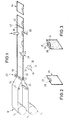
- Fig. 1
- is a schematical perspective view of a preferred manufacturing method,
- Fig. 2
- is a schematical perspective view of a preferred embodiment of the dust bag in its overlaying state,
- Fig. 3
- is a schematical perspective view of the dust bag shown in Fig. 2 in its unfolded state,
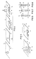
- Fig. 4
- illustrates the steps of another preferred manufacturing process,
- Fig. 5
- illustrates the steps of an additional preferred manufacturing process,
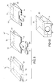
- Figs. 6 to 8
- are schematical side views of dust bags according to the invention with different kinds of preferred mounting elements, and
- Figs. 9 and 10
- illustrate the manufacture of a three-dimensional dust bag according to another preferred embodiment of the invention.
- Fig. 1 shows a preferred manufacturing process according to the invention. In a continuous process two
sheets rolls sheets outer edges device 22. - Accordingly, a flat hose is provided, essentially consisting of two
wall portions upper wall portion 24 and alower wall portion 26, which are sealingly joined together at their longitudinal sides. A mounting means 28 or so-called collar of a relatively stable material, either consisting of a piece of cardboard or a plastic material such as polyethylene or polypropylene may be provided with a layer of adhesive which preferably is laminated onto it or over the entire surface of thecollar 28. Thecollar 28 is provided with at least one line of weakness (perforation or cutting line) so that it can be folded. A first mountingelement 32, i.e. the first half of thecollar 28 is adhered to theupper wall portion 24 along theedge 20 of the bag. A second mountingelement 34, i.e. the second half of thecollar 28 is folded until it can be adhered to thelower wall portion 26 of the dust bag. - The
collar 28 as well as theunderlying wall portions recesses 36 which are semi-circular cuts in the shown manufacturing process. Within the next method step, the twofilter wall portions lines wall portions line 42 to obtaindust bags 44 as shown in Fig. 2. The dust bag withcollar 28 is now ready for use. The two mountingelements elements intake opening 45. The dust bag then automatically unfolds itself and forms a complete bag as shown in Fig. 3. If thedust bag 44 is used, it stays open in its unfolded state. - The continuous hose or tube can be separated into pieces with a straight cut, and further with a cutting tool that provides a rounded edge on the sides. Accordingly some material of the filter has to be discarded. Similarly such cut can also be provided at the
longitudinal edges - The
collar 28 itself can have any shape according to the requirements for the intended use. For example, it can be essentially rectangular, round or elliptical. - Fig. 4 shows another preferred manufacturing method for manufacturing a dust bag according to the invention. Herein the two
recesses wall portions wall portions wall portions wall portions elements dust bag 44 is identical with the dust bag manufactured according to the process described in Fig. 1. - The basic feature of the
collar 28 is that for its intended use it must be brought into an essentially flat configuration and it has to be given inherent stability to be intrinsically stable. This, however, can also be achieved by using separated mountingelements wall portions elements elements collar 28 and thebag 44. - It is essential that the
collar 28 is adhered to the bag in a sealing manner. However, it is not necessary to apply adhesive over the entire surface. For example, adhesive may be applied only in an inner circle while the outer portion is free of adhesive. This may be advantageous when it is necessary to insert the collar into a holding means of the vacuum cleaner. Alternatively, strips of adhesive material are applied onto the upper and lower side of the dust bag, the strip for example being a piece of a so-called transfer tape. Transfer tape on a liner is applied onto the bag whereupon the liner is removed. - Fig. 6 shows an example where the two mounting
elements wall portions common edge 20 of the twowall portions elements hinge 46 or the like. The preferred alternative is shown in Fig. 8 where thecollar 28 preferably consists of a plastic material which is provided with two cuts which only penetrate partially into the material so that essentially two hinges 48,50 are formed. Two hinges 48,50 are preferred to a single one as the width of the dust bag is better accommodated by the distance between the twoadjacent hinges spacer element 52 arranged between the two mountingelements wall portions elements - The intake opening receiving the socket piece can have any suitable form, e.g. the form of a cross. Other configurations can be contemplated, such as a rectangular opening, an elliptical one or anything else. It has to be ensured that in all cases it is possible to open the two
elements collar 28 after assembly so that they form an essentially flat configuration. - While the flat bags appear to be a particularly preferred configuration due to their simplicity and thus relatively low cost, also other configurations of so-called three-dimensional bags 44' as shown in Figs. 9 and 10 are possible. The two
wall portions outer edge 64 of the three-dimensional bag 44'.Recesses 66 are cut in both of thewall portions recesses 66 being open to theouter edge 64 forming anintake opening 70. Thereafter, thecollar 68 is attached to thewall portions collar 68 can be mounted to thewall portions outer edge 64 so that upon formingrecesses 66 in thewall portions collar 68 to create theintake opening 70. - It should, however, be ensured that the
internal folds lower wall portion - According to another embodiment which would allow one to produce a bag in a particularly simple manner, the two opposing wall portions are formed by a single sheet of material, which is folded onto itself with the folding line extending in the feeding direction and defining an outer edge of the dust bag. Then, the sheet is joined together only at the other outer edge. The bag may then be produced in the same manner as depicted in Fig. 1.
Claims (23)
- A dust bag for collecting dust-like material, particularly for vacuum cleaners, with at least two opposing wall portions (24,26) of filter material and with an intake opening, whereinsaid two wall portions (24,26) are connected to each other and define an outer edge (20) of the dust bag,said wall portions (24,26) each have a recess (36a,36b) open to said outer edge (20),the recesses (36a,36b) of said wall portions (24,26) are identical in shape and size and opposed to each other in the overlaying state of said wall portions, andsaid two recesses (36a,36b) of said wall portions (24,26) form said intake opening (45).
- The dust bag according to claim 1, wherein said intake opening (45) is surrounded by a mounting means (28) for mounting the dust bag at the socket piece from which the dust-like material is discharged, said mounting means (28) comprises at least two mounting elements (32,34) each being fixed to one of said two wall portions (24,26) while arranged adjacent to said outer edge (20) and opposed to each other.
- The dust bag according to claim 2 characterized in that the two mounting elements (32,34) are flexibly connected to each other.
- The dust bag according to claim 2 or 3 characterized in that the two mounting elements (32,34) are connected to each other via a spacer element (52) wherein the width of said spacer element (52) corresponds to the thickness of the wall portions (24,26) being arranged between the mounting elements (32,34) in the overlaying state.
- The dust bag according to claim 4 characterized in that the spacer element (52) is flexibly connected to said two mounting elements (32,34).
- The dust bag according to any one of claims 2 to 5 characterized in that the mounting means (28) is made of one piece.
- The dust bag according to claim 6 characterized in that said mounting means (28) comprises a line of weakness along a symmetry axis (30) being in alignment with said outer edge (20).
- The dust bag according to any one of claims 1 to 6, characterized in that at least one of said wall portions (54,56) is additionally folded to form a three-dimensional dust bag.
- The dust bag according to any one of claims 2 to 8 characterized in that said mounting means (28) is made of cardboard or plastic especially polyethylene or polypropylene.
- The dust bag according to any one of claims 2 to 9 characterized in that said mounting means (28) is adhered to said wall portions (24,26) preferably by use of an adhesive.
- A method for manufacturing dust bags for collecting dust-like material, particularly for vacuum cleaners, comprising the steps of:overlaying two wall portions (24,26) of a filter material such that said wall portions (24,26) are connected along an outer edge of the bag, andcutting recesses (36a,36b) into both wall portions (24,26) within one step which recesses (36a,36b) are open to said outer edge and together form an intake opening (45).
- The method for manufacturing dust bags according to claim 11 comprising the additional step after the cutting step:surrounding the recesses (36a,36b) of said wall portions (24,26) with a mounting means (28) at opposite sides of said wall portions (24,26) facing away from each other.
- The method according to claim 12, wherein the mounting means (28) comprises two mounting elements (32,34) each fixed to one wall portion (24,26) adjacent to said outer edge (20) and opposed to each other in the overlaying state of the wall portions (24,26).
- The method for manufacturing dust bags particularly for vacuum cleaners, comprising the steps of:overlaying two wall portions (24,26) of a filter material such that said wall portions (24,26) are connected along an outer edge (20) of the bag, andfixing a mounting element (32,34) to each of said wall portions (24,26) at the outer sides such that the mounting elements (32,34) are opposed to each other and arranged adjacent to said outer edge (20) of said wall portions (24,26), andcutting recesses (36) into both wall portions (24,26) and both mounting elements (32,34) within one step which recesses (36) are open to said outer edge (20) and form an intake opening (45).
- The method according to any one of claims 10 or 14, wherein in the first step two sheets (10,12) of filter material are fed separately and connected to each other to form said two opposing wall portions (24,26) with said outer edge (20).
- The method according to any one of claims 10 or 14, wherein in the first step only one sheet is fed that is folded to form said two opposing wall portions (24,26) with the folding line extending in the feeding direction.
- The method according to claim 15 or 16, wherein at least one of said sheets (10,12) is additionally folded to form a three-dimensional dust bag.
- The method according to any one of claims 11 to 17, wherein the wall portions (24,26) are cut so as to form dust bags after the last step of claim 11 and 14, respectively.
- The method according to claim 18, wherein said two opposing wall portions (24,26) are connected to each other along two connecting lines (38,40), respectively, which are perpendicular to the feeding direction and between which connecting lines (38,40) the wall portions (24,26) are cut so as to form dust bags.
- The method according to claim 19, wherein said recesses (36) are cut simultaneously into two adjacent dust bags prior to separating the wall portions (24,26) into dust bags.
- The method according to any one of claims 18 to 20, wherein all unconnected outer edges of the dust bag are connected prior to separating the wall portions (24,26) into dust bags.
- The method according to any one of claims 18 to 21, wherein the connection of the wall portions (24,26) is performed by heat-sealing or ultrasonic welding or adhering through an adhesive.
- The method according to any one of claims 11 to 22, wherein said mounting means (28) and, respectively, said mounting elements (32,34) as defined in claims 1 to 10 are used.
Priority Applications (3)
| Application Number | Priority Date | Filing Date | Title |
|---|---|---|---|
| EP99110894A EP1059056B1 (en) | 1999-06-08 | 1999-06-08 | Dust bag and method for manufacturing the same |
| DE69921619T DE69921619T2 (en) | 1999-06-08 | 1999-06-08 | Vacuum cleaner bag and method of making the same |
| US09/578,299 US6379409B1 (en) | 1999-06-08 | 2000-05-25 | Dust bag |
Applications Claiming Priority (2)
| Application Number | Priority Date | Filing Date | Title |
|---|---|---|---|
| EP99110894A EP1059056B1 (en) | 1999-06-08 | 1999-06-08 | Dust bag and method for manufacturing the same |
| US09/578,299 US6379409B1 (en) | 1999-06-08 | 2000-05-25 | Dust bag |
Publications (2)
| Publication Number | Publication Date |
|---|---|
| EP1059056A1 true EP1059056A1 (en) | 2000-12-13 |
| EP1059056B1 EP1059056B1 (en) | 2004-11-03 |
Family
ID=26153020
Family Applications (1)
| Application Number | Title | Priority Date | Filing Date |
|---|---|---|---|
| EP99110894A Expired - Lifetime EP1059056B1 (en) | 1999-06-08 | 1999-06-08 | Dust bag and method for manufacturing the same |
Country Status (2)
| Country | Link |
|---|---|
| US (1) | US6379409B1 (en) |
| EP (1) | EP1059056B1 (en) |
Cited By (15)
| Publication number | Priority date | Publication date | Assignee | Title |
|---|---|---|---|---|
| EP1212971A2 (en) * | 2000-12-08 | 2002-06-12 | Vorwerk & Co. Interholding GmbH | Dust bag for vacuum cleaner |
| WO2005034708A1 (en) * | 2003-10-17 | 2005-04-21 | Eurofilters N.V. | Filter bag and method for the production thereof |
| DE10203460B4 (en) * | 2001-01-27 | 2006-05-11 | Wolf Gmbh | In a vacuum cleaner usable filter device |
| WO2006077040A1 (en) * | 2005-01-18 | 2006-07-27 | Miele & Cie. Kg | Vacuum cleaner bag comprising means for compressing the receiving volume, and vacuum cleaner comprising a dust collecting chamber for receiving such vacuum cleaning bags |
| EP1692990A2 (en) * | 2005-02-17 | 2006-08-23 | MELITTA HAUSHALTSPRODUKTE GmbH & Co. Kommanditgesellschaft | Filtering bag for a suction cleaner and process for the manufacture of a suction cleaner filtering bag |
| WO2006104908A2 (en) * | 2005-03-25 | 2006-10-05 | S. C. Johnson & Son, Inc. | Soft-surface remediation device and method of using same |
| WO2007073889A1 (en) * | 2005-12-15 | 2007-07-05 | Eurofilters N.V. | Filter bag for a vacuum cleaner and method for producing the same |
| EP1892087A1 (en) * | 2006-08-23 | 2008-02-27 | Eurofilters Holding N.V | Method for making a vacuum cleaner dust bag |
| WO2011101124A1 (en) | 2010-02-19 | 2011-08-25 | Eurofilters Holding N.V. | Vacuum cleaner filter bag having a side fold |
| EP2366321A1 (en) | 2010-03-19 | 2011-09-21 | Eurofilters Holding N.V. | Vacuum cleaner filter bag |
| DE102010060353A1 (en) * | 2010-11-04 | 2012-05-10 | Papierverarbeitung Görlitz GmbH | Dust filter bag for vacuum cleaner, has receiving opening formed in bag wall toward air inlet opening, and sealing element made of flexible material, where diameter of receiving opening is smaller than or same as diameter of inlet opening |
| EP2452601A1 (en) | 2010-11-10 | 2012-05-16 | Eurofilters Holding N.V. | Vacuum cleaner filter bag with additional attachment device |
| EP2452603A1 (en) | 2010-11-10 | 2012-05-16 | Eurofilters Holding N.V. | Folded vacuum cleaner filter bag |
| CN109591373A (en) * | 2018-12-17 | 2019-04-09 | 江苏广泽环保材料有限公司 | Flattening equipment is used in a kind of production of dust-removal cloth-bag |
| EP3847937B1 (en) | 2020-01-13 | 2022-05-04 | BRANOfilter GmbH | Vacuum cleaner filter bag device |
Families Citing this family (5)
| Publication number | Priority date | Publication date | Assignee | Title |
|---|---|---|---|---|
| DE102006023707B3 (en) * | 2006-05-19 | 2008-01-03 | Eurofilters N.V. | Vacuum Cleaner Bags |
| WO2008051936A2 (en) * | 2006-10-20 | 2008-05-02 | Cummins Filtration Ip | Apparatus, system, and method for manufacturing irregularly shaped panel filters |
| DK2311358T3 (en) * | 2009-10-19 | 2016-02-15 | Eurofilters Holding Nv | A holder plate for a vacuum cleaner filter bag |
| US20120224793A1 (en) * | 2011-03-04 | 2012-09-06 | Trans Western Polymers, Inc. | Polymeric bag with elastic drawtape |
| US10513450B2 (en) | 2016-06-23 | 2019-12-24 | Colgate-Palmolive Company | Wastewater filtration system |
Citations (9)
| Publication number | Priority date | Publication date | Assignee | Title |
|---|---|---|---|---|
| GB954996A (en) * | 1960-02-29 | 1964-04-08 | Heem V D Nv | Dustbag for a suction cleaner |
| US3751881A (en) * | 1970-06-18 | 1973-08-14 | Electrolux Ab | Dust receptacle for a vacuum cleaner |
| DE2310160A1 (en) * | 1973-03-01 | 1974-09-05 | Karl-Heinz Honsel | PROCESS AND MACHINE FOR MANUFACTURING VACUUM CLEANER INSERT BAGS |
| DE2416079A1 (en) * | 1974-04-03 | 1975-10-16 | Klaus Finder | Fixing mach. for reinforcement collars and vacuum cleaner filter bags - has refillable magazines and conveyor belts for precision alignment |
| DE2806305A1 (en) * | 1978-02-15 | 1979-08-16 | Voit Geb | Vacuum cleaner filter bag - has plastics reinforcing sheet attached to suction tube opening side by interposed paper sheet thermo-welded to it |
| EP0179950A1 (en) * | 1984-11-01 | 1986-05-07 | Raymond Leslie Woodley | Improvements relating to sealing arrangements |
| JPH0838402A (en) * | 1994-07-27 | 1996-02-13 | Sanyo Electric Co Ltd | Dust collecting filter for vacuum cleaner |
| JPH0838403A (en) * | 1994-07-27 | 1996-02-13 | Sanyo Electric Co Ltd | Dust collecting filter for vacuum cleaner |
| EP0813839A2 (en) * | 1996-06-19 | 1997-12-29 | Aktiebolaget Electrolux | Method for producing an end closure for a vacuum cleaner dust bag |
Family Cites Families (7)
| Publication number | Priority date | Publication date | Assignee | Title |
|---|---|---|---|---|
| US1995830A (en) * | 1934-01-22 | 1935-03-26 | Augustus L Barnsby | Dust eliminator vacuum cleaner bag emptying device |
| US3392906A (en) * | 1967-04-11 | 1968-07-16 | Studley Paper Company Inc | Vacuum cleaner filter bag |
| US3404515A (en) * | 1967-05-19 | 1968-10-08 | Studley Paper Company Inc | Vacuum cleaner filter bag |
| DE2806306C2 (en) | 1978-02-15 | 1979-12-06 | Bayerische Motoren Werke Ag, 8000 Muenchen | Pressure medium-operated device for adjusting the inclination of a vehicle headlight |
| FI73877C (en) * | 1982-09-29 | 1987-12-10 | Raupak Oy | DAMMPAOSE FOER ANVAENDNING I EN DAMMSUGARE. |
| US5468330A (en) * | 1994-07-01 | 1995-11-21 | Ryan; Michael D. | Apparatus for manufacturing a disposable vacuum cleaner bag |
| SE9604267L (en) * | 1996-11-21 | 1998-05-11 | Anders Rydin | Dust separator for a vacuum cleaner |
-
1999
- 1999-06-08 EP EP99110894A patent/EP1059056B1/en not_active Expired - Lifetime
-
2000
- 2000-05-25 US US09/578,299 patent/US6379409B1/en not_active Expired - Fee Related
Patent Citations (9)
| Publication number | Priority date | Publication date | Assignee | Title |
|---|---|---|---|---|
| GB954996A (en) * | 1960-02-29 | 1964-04-08 | Heem V D Nv | Dustbag for a suction cleaner |
| US3751881A (en) * | 1970-06-18 | 1973-08-14 | Electrolux Ab | Dust receptacle for a vacuum cleaner |
| DE2310160A1 (en) * | 1973-03-01 | 1974-09-05 | Karl-Heinz Honsel | PROCESS AND MACHINE FOR MANUFACTURING VACUUM CLEANER INSERT BAGS |
| DE2416079A1 (en) * | 1974-04-03 | 1975-10-16 | Klaus Finder | Fixing mach. for reinforcement collars and vacuum cleaner filter bags - has refillable magazines and conveyor belts for precision alignment |
| DE2806305A1 (en) * | 1978-02-15 | 1979-08-16 | Voit Geb | Vacuum cleaner filter bag - has plastics reinforcing sheet attached to suction tube opening side by interposed paper sheet thermo-welded to it |
| EP0179950A1 (en) * | 1984-11-01 | 1986-05-07 | Raymond Leslie Woodley | Improvements relating to sealing arrangements |
| JPH0838402A (en) * | 1994-07-27 | 1996-02-13 | Sanyo Electric Co Ltd | Dust collecting filter for vacuum cleaner |
| JPH0838403A (en) * | 1994-07-27 | 1996-02-13 | Sanyo Electric Co Ltd | Dust collecting filter for vacuum cleaner |
| EP0813839A2 (en) * | 1996-06-19 | 1997-12-29 | Aktiebolaget Electrolux | Method for producing an end closure for a vacuum cleaner dust bag |
Non-Patent Citations (1)
| Title |
|---|
| PATENT ABSTRACTS OF JAPAN vol. 1996, no. 06 28 June 1996 (1996-06-28) * |
Cited By (36)
| Publication number | Priority date | Publication date | Assignee | Title |
|---|---|---|---|---|
| EP1212971A3 (en) * | 2000-12-08 | 2003-04-16 | Vorwerk & Co. Interholding GmbH | Dust bag for vacuum cleaner |
| EP1212971A2 (en) * | 2000-12-08 | 2002-06-12 | Vorwerk & Co. Interholding GmbH | Dust bag for vacuum cleaner |
| DE10203460B4 (en) * | 2001-01-27 | 2006-05-11 | Wolf Gmbh | In a vacuum cleaner usable filter device |
| NO337579B1 (en) * | 2003-10-17 | 2016-05-09 | Eurofilters Nv | Filter bag and process for its preparation |
| WO2005034708A1 (en) * | 2003-10-17 | 2005-04-21 | Eurofilters N.V. | Filter bag and method for the production thereof |
| DE10348375A1 (en) * | 2003-10-17 | 2005-05-19 | Eurofilters N.V. | Filter bag and method for its production |
| DE10348375B4 (en) * | 2003-10-17 | 2006-05-04 | Eurofilters N.V. | Filter bag and method for its production |
| US8002862B2 (en) | 2003-10-17 | 2011-08-23 | Eurofilters N.V. | Filter bag and method for the production thereof |
| AU2004280091B2 (en) * | 2003-10-17 | 2010-12-02 | Eurofilters N.V. | Filter bag and method for the production thereof |
| WO2006077040A1 (en) * | 2005-01-18 | 2006-07-27 | Miele & Cie. Kg | Vacuum cleaner bag comprising means for compressing the receiving volume, and vacuum cleaner comprising a dust collecting chamber for receiving such vacuum cleaning bags |
| EP1692990A3 (en) * | 2005-02-17 | 2007-07-25 | MELITTA HAUSHALTSPRODUKTE GmbH & Co. Kommanditgesellschaft | Filtering bag for a suction cleaner and process for the manufacture of a suction cleaner filtering bag |
| EP1692990A2 (en) * | 2005-02-17 | 2006-08-23 | MELITTA HAUSHALTSPRODUKTE GmbH & Co. Kommanditgesellschaft | Filtering bag for a suction cleaner and process for the manufacture of a suction cleaner filtering bag |
| WO2006104908A3 (en) * | 2005-03-25 | 2007-03-22 | Johnson & Son Inc S C | Soft-surface remediation device and method of using same |
| WO2006104908A2 (en) * | 2005-03-25 | 2006-10-05 | S. C. Johnson & Son, Inc. | Soft-surface remediation device and method of using same |
| US7757340B2 (en) | 2005-03-25 | 2010-07-20 | S.C. Johnson & Son, Inc. | Soft-surface remediation device and method of using same |
| WO2007073889A1 (en) * | 2005-12-15 | 2007-07-05 | Eurofilters N.V. | Filter bag for a vacuum cleaner and method for producing the same |
| CN101330859B (en) * | 2005-12-15 | 2011-04-13 | 欧洲过滤袋公司 | Filter bag for vacuum cleaner and production method thereof |
| US8052769B2 (en) | 2005-12-15 | 2011-11-08 | Eurofilters N.V. | Filter bag and method for the production thereof |
| EP1892087A1 (en) * | 2006-08-23 | 2008-02-27 | Eurofilters Holding N.V | Method for making a vacuum cleaner dust bag |
| WO2011101124A1 (en) | 2010-02-19 | 2011-08-25 | Eurofilters Holding N.V. | Vacuum cleaner filter bag having a side fold |
| US8974566B2 (en) | 2010-02-19 | 2015-03-10 | Eurofilters Holding N.V. | Vacuum cleaner filter bag having a side fold |
| EP2366321A1 (en) | 2010-03-19 | 2011-09-21 | Eurofilters Holding N.V. | Vacuum cleaner filter bag |
| US10178932B2 (en) | 2010-03-19 | 2019-01-15 | Eurofilters Holding N.V. | Vacuum cleaner filter bag |
| US10188248B2 (en) | 2010-03-19 | 2019-01-29 | Eurofilters Holding N.V. | Vacuum cleaner filter bag |
| US10182691B2 (en) | 2010-03-19 | 2019-01-22 | Eurofilters Holding N.V. | Vacuum cleaner filter bag |
| WO2011113543A1 (en) | 2010-03-19 | 2011-09-22 | Eurofilters Holding N.V. | Vacuum cleaner filter bag |
| EP2366319A1 (en) | 2010-03-19 | 2011-09-21 | Eurofilters Holding N.V. | Vacuum cleaner filter bag |
| WO2011113544A2 (en) | 2010-03-19 | 2011-09-22 | Eurofilters Holding N.V. | Vacuum cleaner filter bag |
| EP2662010A1 (en) | 2010-03-19 | 2013-11-13 | Eurofilters Holding N.V. | Vacuum cleaner filter bag |
| DE102010060353A1 (en) * | 2010-11-04 | 2012-05-10 | Papierverarbeitung Görlitz GmbH | Dust filter bag for vacuum cleaner, has receiving opening formed in bag wall toward air inlet opening, and sealing element made of flexible material, where diameter of receiving opening is smaller than or same as diameter of inlet opening |
| WO2012062458A1 (en) | 2010-11-10 | 2012-05-18 | Eurofilters Holding N.V. | Folded vacuum cleaner filter bag |
| WO2012062457A1 (en) | 2010-11-10 | 2012-05-18 | Eurofilters Holding N.V. | Vacuum cleaner filter bag having an additional attachment device |
| EP2452603A1 (en) | 2010-11-10 | 2012-05-16 | Eurofilters Holding N.V. | Folded vacuum cleaner filter bag |
| EP2452601A1 (en) | 2010-11-10 | 2012-05-16 | Eurofilters Holding N.V. | Vacuum cleaner filter bag with additional attachment device |
| CN109591373A (en) * | 2018-12-17 | 2019-04-09 | 江苏广泽环保材料有限公司 | Flattening equipment is used in a kind of production of dust-removal cloth-bag |
| EP3847937B1 (en) | 2020-01-13 | 2022-05-04 | BRANOfilter GmbH | Vacuum cleaner filter bag device |
Also Published As
| Publication number | Publication date |
|---|---|
| EP1059056B1 (en) | 2004-11-03 |
| US6379409B1 (en) | 2002-04-30 |
Similar Documents
| Publication | Publication Date | Title |
|---|---|---|
| US6379409B1 (en) | Dust bag | |
| EP1250999B1 (en) | Method of manufacturing a gusset bag | |
| EP0163755A1 (en) | Square ended bag | |
| US20070175190A1 (en) | Filter bag and method for the production thereof | |
| EP0227266B1 (en) | Orally operable water filter | |
| EP1371569A1 (en) | Bag | |
| JPH07222904A (en) | Unit type filter | |
| US20090090092A1 (en) | Filter Bag and Method for the Production Thereof | |
| JPH0679810A (en) | Continuous form incorporating return envelop | |
| JP2019018871A (en) | Packing box | |
| EP0630219B1 (en) | Collection bags and method for producing such bags | |
| WO2001003561A1 (en) | Disposable cleaning means | |
| ATE246125T1 (en) | BAG PACKING OF BAGS MADE OF THERMOPLASTIC PLASTIC FILM AND METHOD FOR THE PRODUCTION THEREOF | |
| EP1187548B1 (en) | Dust container | |
| JP3601233B2 (en) | filter | |
| JP4550406B2 (en) | Bag filter and bag filter manufacturing method | |
| EP1449490A1 (en) | A protective external casing for refuse containers | |
| EP3525982A1 (en) | Drill dust receptacle and blank therefore | |
| JP2004181974A (en) | Manufacturing method for gusset bag and its device | |
| EP0588938B1 (en) | Waste receptacle incorporating a bag supply unit | |
| US20230012256A1 (en) | Vacuum bag | |
| JP3967258B2 (en) | Dripper | |
| DE69921619T2 (en) | Vacuum cleaner bag and method of making the same | |
| EP0813839A2 (en) | Method for producing an end closure for a vacuum cleaner dust bag | |
| KR20060022641A (en) | Dust-collecting filter for electrical cleaner |
Legal Events
| Date | Code | Title | Description |
|---|---|---|---|
| PUAI | Public reference made under article 153(3) epc to a published international application that has entered the european phase |
Free format text: ORIGINAL CODE: 0009012 |
|
| AK | Designated contracting states |
Kind code of ref document: A1 Designated state(s): DE FR GB IT NL SE |
|
| AX | Request for extension of the european patent |
Free format text: AL;LT;LV;MK;RO;SI |
|
| 17P | Request for examination filed |
Effective date: 20010607 |
|
| AKX | Designation fees paid |
Free format text: DE FR GB IT NL SE |
|
| 17Q | First examination report despatched |
Effective date: 20030409 |
|
| GRAP | Despatch of communication of intention to grant a patent |
Free format text: ORIGINAL CODE: EPIDOSNIGR1 |
|
| GRAS | Grant fee paid |
Free format text: ORIGINAL CODE: EPIDOSNIGR3 |
|
| GRAA | (expected) grant |
Free format text: ORIGINAL CODE: 0009210 |
|
| AK | Designated contracting states |
Kind code of ref document: B1 Designated state(s): DE FR GB IT NL SE |
|
| REG | Reference to a national code |
Ref country code: GB Ref legal event code: FG4D |
|
| REF | Corresponds to: |
Ref document number: 69921619 Country of ref document: DE Date of ref document: 20041209 Kind code of ref document: P |
|
| REG | Reference to a national code |
Ref country code: SE Ref legal event code: TRGR |
|
| PLBE | No opposition filed within time limit |
Free format text: ORIGINAL CODE: 0009261 |
|
| STAA | Information on the status of an ep patent application or granted ep patent |
Free format text: STATUS: NO OPPOSITION FILED WITHIN TIME LIMIT |
|
| 26N | No opposition filed |
Effective date: 20050804 |
|
| ET | Fr: translation filed | ||
| PGFP | Annual fee paid to national office [announced via postgrant information from national office to epo] |
Ref country code: NL Payment date: 20070624 Year of fee payment: 9 |
|
| PGFP | Annual fee paid to national office [announced via postgrant information from national office to epo] |
Ref country code: DE Payment date: 20070731 Year of fee payment: 9 |
|
| PGFP | Annual fee paid to national office [announced via postgrant information from national office to epo] |
Ref country code: GB Payment date: 20070628 Year of fee payment: 9 |
|
| PGFP | Annual fee paid to national office [announced via postgrant information from national office to epo] |
Ref country code: IT Payment date: 20070625 Year of fee payment: 9 |
|
| PGFP | Annual fee paid to national office [announced via postgrant information from national office to epo] |
Ref country code: SE Payment date: 20070627 Year of fee payment: 9 |
|
| PGFP | Annual fee paid to national office [announced via postgrant information from national office to epo] |
Ref country code: FR Payment date: 20070618 Year of fee payment: 9 |
|
| EUG | Se: european patent has lapsed | ||
| GBPC | Gb: european patent ceased through non-payment of renewal fee |
Effective date: 20080608 |
|
| NLV4 | Nl: lapsed or anulled due to non-payment of the annual fee |
Effective date: 20090101 |
|
| REG | Reference to a national code |
Ref country code: FR Ref legal event code: ST Effective date: 20090228 |
|
| PG25 | Lapsed in a contracting state [announced via postgrant information from national office to epo] |
Ref country code: DE Free format text: LAPSE BECAUSE OF NON-PAYMENT OF DUE FEES Effective date: 20090101 |
|
| PG25 | Lapsed in a contracting state [announced via postgrant information from national office to epo] |
Ref country code: NL Free format text: LAPSE BECAUSE OF NON-PAYMENT OF DUE FEES Effective date: 20090101 |
|
| PG25 | Lapsed in a contracting state [announced via postgrant information from national office to epo] |
Ref country code: GB Free format text: LAPSE BECAUSE OF NON-PAYMENT OF DUE FEES Effective date: 20080608 |
|
| PG25 | Lapsed in a contracting state [announced via postgrant information from national office to epo] |
Ref country code: IT Free format text: LAPSE BECAUSE OF NON-PAYMENT OF DUE FEES Effective date: 20080608 Ref country code: FR Free format text: LAPSE BECAUSE OF NON-PAYMENT OF DUE FEES Effective date: 20080630 |
|
| PG25 | Lapsed in a contracting state [announced via postgrant information from national office to epo] |
Ref country code: SE Free format text: LAPSE BECAUSE OF NON-PAYMENT OF DUE FEES Effective date: 20080609 |