EP0813839A2 - Method for producing an end closure for a vacuum cleaner dust bag - Google Patents
Method for producing an end closure for a vacuum cleaner dust bag Download PDFInfo
- Publication number
- EP0813839A2 EP0813839A2 EP97850091A EP97850091A EP0813839A2 EP 0813839 A2 EP0813839 A2 EP 0813839A2 EP 97850091 A EP97850091 A EP 97850091A EP 97850091 A EP97850091 A EP 97850091A EP 0813839 A2 EP0813839 A2 EP 0813839A2
- Authority
- EP
- European Patent Office
- Prior art keywords
- work piece
- flap
- folded
- bag
- stage
- Prior art date
- Legal status (The legal status is an assumption and is not a legal conclusion. Google has not performed a legal analysis and makes no representation as to the accuracy of the status listed.)
- Withdrawn
Links
Images

Classifications
-
- A—HUMAN NECESSITIES
- A47—FURNITURE; DOMESTIC ARTICLES OR APPLIANCES; COFFEE MILLS; SPICE MILLS; SUCTION CLEANERS IN GENERAL
- A47L—DOMESTIC WASHING OR CLEANING; SUCTION CLEANERS IN GENERAL
- A47L9/00—Details or accessories of suction cleaners, e.g. mechanical means for controlling the suction or for effecting pulsating action; Storing devices specially adapted to suction cleaners or parts thereof; Carrying-vehicles specially adapted for suction cleaners
- A47L9/10—Filters; Dust separators; Dust removal; Automatic exchange of filters
- A47L9/14—Bags or the like; Rigid filtering receptacles; Attachment of, or closures for, bags or receptacles
- A47L9/1427—Means for mounting or attaching bags or filtering receptacles in suction cleaners; Adapters
- A47L9/1436—Connecting plates, e.g. collars, end closures
Definitions
- This invention relates to a method for producing an end closure for a vacuum cleaner dust bag by manufacturing in a first stage a tube shaped work piece comprising an outer layer and one or several lined layers.
- a seperate sealing piece comprising a layer of a rather non porous but air pervious material, such as the outer layer material of the bag, is glued on the outside of the bottom part or the top part of the bag.
- These sealing pieces are, when they are glued to the outer layer, so flexible that they easily follow the contour of the outside layers.
- the purpose of this invention is to fascilitate the production process by eliminating these sealing operations . This is achieved by means of a method having the characteristics mentioned in the claims.
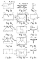
- FIG. 1 is a perspective view of a bag for which the method according to the invention is used
- Figs. 2-6 are three separate projections of different stages of the manufacturing procedure (where a and c are side views and b are end views)
- Fig. 7 is a perspective view of a part of the bag as shown in Fig. 5.
- Fig. 1 shows the finished dust bag which is produced from a tube shaped work piece having several layers of air pervious material 10.
- the bag has an upper mainly flat top part 11 on which a plate 12 of comparatively stiff material such as cardboard or plastic is fastened.
- the plate 12 as well as the top part 11 has an opening 13 through which a sleeve arranged on the vacuum cleaner is inserted in order to distribute the dirty air into the bag.
- the opening 13 might be provided with an elastic membrane 14 partly covering the opening 13 and forming a seal against the sleeve.
- the bag is also provided with a bottom part 15. At least one of the end parts 11, 15 described above is manufactured in accordance with the principle described below.
- a tube shaped work piece 16 comprises an outer layer 16a and one or several inner lined layers 16b together forming the air pervious material 10.
- the outer layer serves as a fine filter having a larger flow resistance and being tighter than the inner layers who serve as a porous coarse filter.
- the work piece is cut into suitable lengths in order to form the finished bag by successive folding and glueing operations.
- Fig. 2 one end of the cut work piece is shown in the flattened out position the work piece having two opposite, inwardly directed folds 17 extending in the length direction.
- Two recesses 18 and 19 respectively which together form the opening 13 in the finished bag might be provided. If the end is used to form the bottom no recesses are produced.
- the far away side of the work piece according to Fig. 2a is also provided with two cuts 20 extending in the length direction through the outer layer 16a.
- the work piece is then, according to what is shown in Fig. 3, provided with folding lines 21, 22 and 23 resp. thereby forming a rectangular collar shaped part 24 having four wall parts 24a, 24b, 24c and 24d.
- the wall parts 24b and 24d are folded inwardly as appears from Fig. 4 after which one side of the wall part 24a is provided with glue on the areas which do not have any lined layers and is according to what is shown in Fig. 5 is folded inwardly so that it partly covers the two wall parts 24b and 24d and is secured to them.
- the inner lined layer 16b will be folded twice within the triangular areas 25 (Fig.
- the plate 12 might then be applied on the end part whereas the other end of the work piece is closed by the same method or in some other way.
- the advantage with the arrangement according to the invention is that glueing takes place directly between the outer layers at the area 27 which gives a sealed connection without using special sealing pieces or by admitting the glue to penetrate the porous lined material.
Abstract
This invention relates to a method for producing an end closure for a vacuum cleaner dust bag by manufacturing in a first stage a tube shaped work piece comprising an outer layer and one or several lined layers. The work piece is in a second stage severed mainly perpendicular to the length direction of the tube shaped work piece and the outer layer is (16a) in connection with said severing operation is provided with one or several cuts or recesses extending from the cut edge in order to form a flap (26). In a third stage parts of the end area of the work piece are successively folded inwardly and in connection therewith the lined layer or layers (16b) are folded inwardly or are removed within a portion of the area defined by the flap in order to uncover a part of the inwardly facing side (area 27) of the outer layer. The flap is then provided with glueing material on the uncovered surfaces and is arranged to overlap at least one of the the remaining inwardly folded end areas of the work piece.

Description
- This invention relates to a method for producing an end closure for a vacuum cleaner dust bag by manufacturing in a first stage a tube shaped work piece comprising an outer layer and one or several lined layers.
- It is previously known to manufacture dust bags for vacuum cleaners by cutting, folding and glueing a tube shaped work piece comprising several layers. All the layers are made from air pervious materal but the outer layer is more homogenous and less porous than the inner layer or layers. The end parts of the work piece are folded to form either a bottom or a top of the dust bag and in case the end part is designed to form a top an opening is formed in the layers. The top is usually glued to a cardboard plate having an air inlet opening which is partly covered by a membrane.
- When manufacturing all these types of vacuum cleaner dust bags it is difficult to completely seal the inside from the outside of the bag at the folded areas since it is difficult to get the glue to penetrate the porous inner layers. Also when the different layers are folded and placed on each other the height of the different folds becomes rather large which means that it is difficult to glue two folded layers to each other on each side of a third folded layer or to glue the cardboard plate evenly to all folded layers beneath. Instead small air channels are are formed through the pourus inner layers and close to the folds through which air leaks out from the bag.
- In order to partly overcome this problem a seperate sealing piece comprising a layer of a rather non porous but air pervious material, such as the outer layer material of the bag, is glued on the outside of the bottom part or the top part of the bag. These sealing pieces are, when they are glued to the outer layer, so flexible that they easily follow the contour of the outside layers. As an alternative it is possible to laminate by glueing or by safeguarding that the glue penetrates the lined material but these alternative methods are complicated from a manufacturing point of view and also expensive.
- The purpose of this invention is to fascilitate the production process by eliminating these sealing operations . This is achieved by means of a method having the characteristics mentioned in the claims.
- An embodiment of the invention will now be described with reference to the accompanying drawings on which Fig. 1 is a perspective view of a bag for which the method according to the invention is used, Figs. 2-6 are three separate projections of different stages of the manufacturing procedure (where a and c are side views and b are end views) whereas Fig. 7 is a perspective view of a part of the bag as shown in Fig. 5.
- Fig. 1 shows the finished dust bag which is produced from a tube shaped work piece having several layers of air
pervious material 10. The bag has an upper mainly flat top part 11 on which aplate 12 of comparatively stiff material such as cardboard or plastic is fastened. Theplate 12 as well as the top part 11 has an opening 13 through which a sleeve arranged on the vacuum cleaner is inserted in order to distribute the dirty air into the bag. The opening 13 might be provided with anelastic membrane 14 partly covering theopening 13 and forming a seal against the sleeve. The bag is also provided with abottom part 15. At least one of theend parts 11, 15 described above is manufactured in accordance with the principle described below. - A tube shaped
work piece 16 comprises anouter layer 16a and one or several inner linedlayers 16b together forming the airpervious material 10. The outer layer serves as a fine filter having a larger flow resistance and being tighter than the inner layers who serve as a porous coarse filter. The work piece is cut into suitable lengths in order to form the finished bag by successive folding and glueing operations. In Fig. 2 one end of the cut work piece is shown in the flattened out position the work piece having two opposite, inwardly directedfolds 17 extending in the length direction. Two recesses 18 and 19 respectively which together form the opening 13 in the finished bag might be provided. If the end is used to form the bottom no recesses are produced. The far away side of the work piece according to Fig. 2a is also provided with twocuts 20 extending in the length direction through theouter layer 16a. - The work piece is then, according to what is shown in Fig. 3, provided with
folding lines part 24 having fourwall parts wall parts wall parts wall parts layer 16b will be folded twice within the triangular areas 25 (Fig. 5) of theflap 26 which is formed between the twocuts 20 of the wall part 24c whereas theareas 27 on the outer layer of the same flap is simultaneously uncovered. Theareas 27 can, as well as the remaining parts of the flap 24c, which is not provided with the lined layers then be provided with glue after which the wall part 24c is folded inwardly to the position shown in Fig. 6 which means that the end part is closed and effectively sealed. - The
plate 12 might then be applied on the end part whereas the other end of the work piece is closed by the same method or in some other way. Thus, the advantage with the arrangement according to the invention is that glueing takes place directly between the outer layers at thearea 27 which gives a sealed connection without using special sealing pieces or by admitting the glue to penetrate the porous lined material.
Claims (5)
- Method for producing an end closure for a vacuum cleaner dust bag by manufacturing in a first stage a tube shaped work piece comprising an outer layer and one or several lined layers, characterized in that the work piece is in a second stage severed mainly perpendicular to the length direction of the tube shaped work piece to form a cut edge and that the outer layer (16a) in connection with said severing operation is provided with one or several cuts or recesses (20) extending from the cut edge in order to form a flap (26) and that in a third stage parts of the end area of the work piece are successively folded away and that in connection therewith the lined layer or layers (16b) are folded inwardly or are removed within a portion of the area defined by the flap in order to uncover a part of the inwardly facing side (area 27) of the outer layer and that the flap is then provided with glueing material on the uncovered surfaces and is arranged to overlap at least one of the the remaining inwardly folded end areas of the work piece.
- Method according to claim 1, characterized in that the tube shaped work piece before being severed is provided with two opposite inwardly facing folds (17) and that the parts of the end areas in the third stage are folded such that a bottom and/or a top part is formed in the bag said part having two opposite mainly rectangular portions (24b,24d) which are partly overlapped of a mainly trapezi formed third part (24a) which is at least partly overlapped by a fourth opposite portion (24c) comprising said flap (26).
- Method according to claim 1 or 2, characterized in that there are two cuts (20) which are mainly parallel with the length direction of the tube shaped work piece.
- Method according to any of the preceding claims, characterized in that the flap and the end area is provided with edge recesses (18,19) which after folding of the bag together forms an opening (13) in the bag.
- Method according to any of the preceding claims , characterized in that a plate (12) which is provided with an opening is fixed by glueing at the outside of the bag at the end areas which are folded inwardly.
Applications Claiming Priority (2)
| Application Number | Priority Date | Filing Date | Title |
|---|---|---|---|
| SE9602422A SE9602422L (en) | 1996-06-19 | 1996-06-19 | Ways to manufacture an end seal for a vacuum cleaner bag |
| SE9602422 | 1996-06-19 |
Publications (2)
| Publication Number | Publication Date |
|---|---|
| EP0813839A2 true EP0813839A2 (en) | 1997-12-29 |
| EP0813839A3 EP0813839A3 (en) | 1999-02-03 |
Family
ID=20403073
Family Applications (1)
| Application Number | Title | Priority Date | Filing Date |
|---|---|---|---|
| EP97850091A Withdrawn EP0813839A3 (en) | 1996-06-19 | 1997-06-10 | Method for producing an end closure for a vacuum cleaner dust bag |
Country Status (2)
| Country | Link |
|---|---|
| EP (1) | EP0813839A3 (en) |
| SE (1) | SE9602422L (en) |
Cited By (3)
| Publication number | Priority date | Publication date | Assignee | Title |
|---|---|---|---|---|
| EP1059056A1 (en) * | 1999-06-08 | 2000-12-13 | 3M Innovative Properties Company | Dust bag and method for manufacturing the same |
| WO2005034708A1 (en) * | 2003-10-17 | 2005-04-21 | Eurofilters N.V. | Filter bag and method for the production thereof |
| WO2006077040A1 (en) * | 2005-01-18 | 2006-07-27 | Miele & Cie. Kg | Vacuum cleaner bag comprising means for compressing the receiving volume, and vacuum cleaner comprising a dust collecting chamber for receiving such vacuum cleaning bags |
Citations (6)
| Publication number | Priority date | Publication date | Assignee | Title |
|---|---|---|---|---|
| US2792076A (en) * | 1954-04-22 | 1957-05-14 | Lewyt Corp | Filter bag |
| US3276192A (en) * | 1963-06-11 | 1966-10-04 | Studley Paper Company Inc | Disposable filter bag |
| US3330100A (en) * | 1964-04-08 | 1967-07-11 | Studley Paper Company Inc | Vacuum cleaner filter bag |
| US3738091A (en) * | 1971-05-24 | 1973-06-12 | Studley Paper Co | Vacuum cleaner filter bag |
| GB1506577A (en) * | 1975-05-23 | 1978-04-05 | Drg Ltd | Vacuum cleaner bags |
| US4322259A (en) * | 1979-06-20 | 1982-03-30 | Studley Paper Company, Inc. | Method of making a reinforced vacuum cleaner filter bag |
-
1996
- 1996-06-19 SE SE9602422A patent/SE9602422L/en not_active Application Discontinuation
-
1997
- 1997-06-10 EP EP97850091A patent/EP0813839A3/en not_active Withdrawn
Patent Citations (6)
| Publication number | Priority date | Publication date | Assignee | Title |
|---|---|---|---|---|
| US2792076A (en) * | 1954-04-22 | 1957-05-14 | Lewyt Corp | Filter bag |
| US3276192A (en) * | 1963-06-11 | 1966-10-04 | Studley Paper Company Inc | Disposable filter bag |
| US3330100A (en) * | 1964-04-08 | 1967-07-11 | Studley Paper Company Inc | Vacuum cleaner filter bag |
| US3738091A (en) * | 1971-05-24 | 1973-06-12 | Studley Paper Co | Vacuum cleaner filter bag |
| GB1506577A (en) * | 1975-05-23 | 1978-04-05 | Drg Ltd | Vacuum cleaner bags |
| US4322259A (en) * | 1979-06-20 | 1982-03-30 | Studley Paper Company, Inc. | Method of making a reinforced vacuum cleaner filter bag |
Cited By (6)
| Publication number | Priority date | Publication date | Assignee | Title |
|---|---|---|---|---|
| EP1059056A1 (en) * | 1999-06-08 | 2000-12-13 | 3M Innovative Properties Company | Dust bag and method for manufacturing the same |
| US6379409B1 (en) | 1999-06-08 | 2002-04-30 | 3M Innovative Properties Company | Dust bag |
| WO2005034708A1 (en) * | 2003-10-17 | 2005-04-21 | Eurofilters N.V. | Filter bag and method for the production thereof |
| AU2004280091B2 (en) * | 2003-10-17 | 2010-12-02 | Eurofilters N.V. | Filter bag and method for the production thereof |
| US8002862B2 (en) | 2003-10-17 | 2011-08-23 | Eurofilters N.V. | Filter bag and method for the production thereof |
| WO2006077040A1 (en) * | 2005-01-18 | 2006-07-27 | Miele & Cie. Kg | Vacuum cleaner bag comprising means for compressing the receiving volume, and vacuum cleaner comprising a dust collecting chamber for receiving such vacuum cleaning bags |
Also Published As
| Publication number | Publication date |
|---|---|
| SE9602422D0 (en) | 1996-06-19 |
| EP0813839A3 (en) | 1999-02-03 |
| SE9602422L (en) | 1997-12-20 |
Similar Documents
| Publication | Publication Date | Title |
|---|---|---|
| US3432998A (en) | End closure for disposable vacuum cleaner dust bag | |
| US5729955A (en) | Method of manufacturing packet with wet tissues | |
| US5725620A (en) | Manually closable vacuum cleaner bag | |
| US6379409B1 (en) | Dust bag | |
| KR20020026261A (en) | Flexible storage bag with closure indicator | |
| US4759640A (en) | Rose-bottom or block-bottom valve bag | |
| US8052769B2 (en) | Filter bag and method for the production thereof | |
| WO1994011089A1 (en) | Filter element | |
| US3237846A (en) | End closure for disposable dust bag | |
| EP0813839A2 (en) | Method for producing an end closure for a vacuum cleaner dust bag | |
| US2672213A (en) | Filter and method of making the same | |
| EP1053184B1 (en) | Close sack with air exhaustion | |
| US4381192A (en) | Filter bag for vacuum cleaner | |
| KR100219988B1 (en) | Dust collecting paper bag for vacuum cleaner | |
| US2832433A (en) | Rectangular filter bags | |
| EP1187548B1 (en) | Dust container | |
| EP1284629B1 (en) | Dust container | |
| SE9100286D0 (en) | PARTY FOR DAMSUGAR PASS | |
| EP0809963A2 (en) | Vacuum cleaner dust bag | |
| US3440805A (en) | Vacuum cleaner filter bag | |
| EP0676229A1 (en) | Air filter with polyurethane support, particularly for motor vehicle passenger compartment | |
| KR970005515B1 (en) | Paper bag of a vacuum cleaner | |
| EP0062326B1 (en) | Procedure for manufacturing paper bags | |
| JPH0711735Y2 (en) | Dust bag for vacuum cleaner | |
| EP0922638A2 (en) | Method for filling a valve bag, and a valve bag |
Legal Events
| Date | Code | Title | Description |
|---|---|---|---|
| PUAI | Public reference made under article 153(3) epc to a published international application that has entered the european phase |
Free format text: ORIGINAL CODE: 0009012 |
|
| AK | Designated contracting states |
Kind code of ref document: A2 Designated state(s): BE DE FR SE |
|
| PUAL | Search report despatched |
Free format text: ORIGINAL CODE: 0009013 |
|
| AK | Designated contracting states |
Kind code of ref document: A3 Designated state(s): AT BE CH DE DK ES FI FR GB GR IE IT LI LU MC NL PT SE |
|
| AKX | Designation fees paid |
Free format text: BE DE FR SE |
|
| STAA | Information on the status of an ep patent application or granted ep patent |
Free format text: STATUS: THE APPLICATION IS DEEMED TO BE WITHDRAWN |
|
| 18D | Application deemed to be withdrawn |
Effective date: 19990804 |