EP2660079B1 - Reifen - Google Patents
Reifen Download PDFInfo
- Publication number
- EP2660079B1 EP2660079B1 EP11853086.4A EP11853086A EP2660079B1 EP 2660079 B1 EP2660079 B1 EP 2660079B1 EP 11853086 A EP11853086 A EP 11853086A EP 2660079 B1 EP2660079 B1 EP 2660079B1
- Authority
- EP
- European Patent Office
- Prior art keywords
- tire
- groove
- protrusion portions
- groove portion
- sidewall
- Prior art date
- Legal status (The legal status is an assumption and is not a legal conclusion. Google has not performed a legal analysis and makes no representation as to the accuracy of the status listed.)
- Not-in-force
Links
- 230000005855 radiation Effects 0.000 description 8
- 230000000694 effects Effects 0.000 description 5
- 230000007423 decrease Effects 0.000 description 4
- 238000010276 construction Methods 0.000 description 3
- 230000003247 decreasing effect Effects 0.000 description 3
- 238000000034 method Methods 0.000 description 2
- 238000012986 modification Methods 0.000 description 2
- 230000004048 modification Effects 0.000 description 2
- MGGVALXERJRIRO-UHFFFAOYSA-N 4-[2-(2,3-dihydro-1H-inden-2-ylamino)pyrimidin-5-yl]-2-[2-oxo-2-(2,4,6,7-tetrahydrotriazolo[4,5-c]pyridin-5-yl)ethyl]-1H-pyrazol-5-one Chemical compound C1C(CC2=CC=CC=C12)NC1=NC=C(C=N1)C=1C(=NN(C=1)CC(=O)N1CC2=C(CC1)NN=N2)O MGGVALXERJRIRO-UHFFFAOYSA-N 0.000 description 1
- IJGRMHOSHXDMSA-UHFFFAOYSA-N Atomic nitrogen Chemical compound N#N IJGRMHOSHXDMSA-UHFFFAOYSA-N 0.000 description 1
- 230000001154 acute effect Effects 0.000 description 1
- 239000000470 constituent Substances 0.000 description 1
- 229910001873 dinitrogen Inorganic materials 0.000 description 1
- 239000007789 gas Substances 0.000 description 1
- 230000000630 rising effect Effects 0.000 description 1
- 230000001629 suppression Effects 0.000 description 1
Images


Classifications
-
- B—PERFORMING OPERATIONS; TRANSPORTING
- B60—VEHICLES IN GENERAL
- B60C—VEHICLE TYRES; TYRE INFLATION; TYRE CHANGING; CONNECTING VALVES TO INFLATABLE ELASTIC BODIES IN GENERAL; DEVICES OR ARRANGEMENTS RELATED TO TYRES
- B60C11/00—Tyre tread bands; Tread patterns; Anti-skid inserts
-
- B—PERFORMING OPERATIONS; TRANSPORTING
- B60—VEHICLES IN GENERAL
- B60C—VEHICLE TYRES; TYRE INFLATION; TYRE CHANGING; CONNECTING VALVES TO INFLATABLE ELASTIC BODIES IN GENERAL; DEVICES OR ARRANGEMENTS RELATED TO TYRES
- B60C11/00—Tyre tread bands; Tread patterns; Anti-skid inserts
- B60C11/03—Tread patterns
- B60C11/04—Tread patterns in which the raised area of the pattern consists only of continuous circumferential ribs, e.g. zig-zag
- B60C11/042—Tread patterns in which the raised area of the pattern consists only of continuous circumferential ribs, e.g. zig-zag further characterised by the groove cross-section
-
- B—PERFORMING OPERATIONS; TRANSPORTING
- B60—VEHICLES IN GENERAL
- B60C—VEHICLE TYRES; TYRE INFLATION; TYRE CHANGING; CONNECTING VALVES TO INFLATABLE ELASTIC BODIES IN GENERAL; DEVICES OR ARRANGEMENTS RELATED TO TYRES
- B60C11/00—Tyre tread bands; Tread patterns; Anti-skid inserts
- B60C11/03—Tread patterns
- B60C11/13—Tread patterns characterised by the groove cross-section, e.g. for buttressing or preventing stone-trapping
- B60C11/1307—Tread patterns characterised by the groove cross-section, e.g. for buttressing or preventing stone-trapping with special features of the groove walls
- B60C2011/1338—Tread patterns characterised by the groove cross-section, e.g. for buttressing or preventing stone-trapping with special features of the groove walls comprising protrusions
-
- B—PERFORMING OPERATIONS; TRANSPORTING
- B60—VEHICLES IN GENERAL
- B60C—VEHICLE TYRES; TYRE INFLATION; TYRE CHANGING; CONNECTING VALVES TO INFLATABLE ELASTIC BODIES IN GENERAL; DEVICES OR ARRANGEMENTS RELATED TO TYRES
- B60C11/00—Tyre tread bands; Tread patterns; Anti-skid inserts
- B60C11/03—Tread patterns
- B60C11/13—Tread patterns characterised by the groove cross-section, e.g. for buttressing or preventing stone-trapping
- B60C11/1353—Tread patterns characterised by the groove cross-section, e.g. for buttressing or preventing stone-trapping with special features of the groove bottom
- B60C2011/1361—Tread patterns characterised by the groove cross-section, e.g. for buttressing or preventing stone-trapping with special features of the groove bottom with protrusions extending from the groove bottom
-
- B—PERFORMING OPERATIONS; TRANSPORTING
- B60—VEHICLES IN GENERAL
- B60C—VEHICLE TYRES; TYRE INFLATION; TYRE CHANGING; CONNECTING VALVES TO INFLATABLE ELASTIC BODIES IN GENERAL; DEVICES OR ARRANGEMENTS RELATED TO TYRES
- B60C2200/00—Tyres specially adapted for particular applications
- B60C2200/06—Tyres specially adapted for particular applications for heavy duty vehicles
Definitions
- the present invention relates to a tire that suppresses a temperature increase of a tire due to running.
- a pneumatic tire hereinafter, a tire mounted on a vehicle
- various methods have been used to suppress a temperature increase of a tire due to vehicle running.
- a temperature increase is remarkable in a heavy-duty tire for a truck, bus, construction vehicle and the like.
- a tire having a number of fin-shaped protrusions in a sidewall portion has been known.
- a fin-shaped protrusions causes turbulence in an airflow passing through a sidewall surface, the turbulence accelerates heat radiation from a tire, and a temperature increase of a sidewall portion is suppressed.
- EP1541383 discloses a tire with particular under flow characteristics.
- PTL1 Japanese Patent Application Publication 2009-160994 (Pages 4 to 5, Fig. 2 )
- the conventional tire described above has a point to be improved. That is, there are limitations to effective suppression of a temperature increase in a tread portion only by a protrusion in a sidewall portion.
- the present invention has been made in view of such a situation. Accordingly, it is an object of the invention to provide a tire that can effectively suppress a temperature increase of a tread portion due to vehicle running.
- a rubber gauge thickness
- a rubber volume is large. If such a heavy-duty tire repeatedly deforms, a temperature of a tread portion increases.
- the inventor of the present application has found that a main heat source exists particularly in a tread portion outside a tire radial direction rather than in a belt layer near a tire equator line in such a heavy-duty tire.
- the feature of the present invention is summarized as a tire (pneumatic tire 10) in which a groove portion (groove portion 30) extending in a tire circumferential direction is formed in a tread portion (tread portion 20), wherein: in a groove bottom (groove bottom 32) of the groove portion, a plurality of protrusion portions (protrusion portions 100) are provided, the protrusion portions extend from one sidewall (sidewall 31) forming the groove portion toward the other sidewall (sidewall 32) facing the one sidewall, the protrusion portions are provided at predetermined interval in the groove portion, and when the length of the protrusion portions along the groove center line is L and the predetermined interval is P, in a tread surface view of the tire, the relation of 1.25 ⁇ P ⁇ 10L is satisfied.
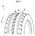
- Fig. 1 is a schematic perspective view of a pneumatic tire 10 according to the present embodiment.
- the pneumatic tire 10 is a pneumatic radial tire mounted on a truck or bus (TBR) or a construction vehicle (ORR) such as a dump truck.
- the pneumatic tire 10 may be filled with inactive gas such as nitrogen gas.
- the pneumatic tire 10 has a tread portion 20 that may contact with a road surface.
- the tread portion 20 has a groove portion 30 formed therein.
- the groove portion 30 is a linear groove extending in a tire circumference direction.
- a plurality of protrusion portions 100 are provided inside the groove portion 30.
- the pneumatic tire 10 is mounted on a vehicle to rotate in the rotational direction R when the vehicle moves forward.
- the rotational direction when the pneumatic tire 10 is mounted is not specified.
- Fig. 2 is a sectional view of the pneumatic tire 10 along the tread width direction and tire radial direction.
- the pneumatic tire 10 has a belt layer 40 comprised of a plurality of belts.
- a rubber gauge (thickness) of the tread portion 20 of the pneumatic tire 10 is larger.
- the pneumatic tire 10 satisfies DC/OD ⁇ 0.015.
- the tire outer diameter OD means the diameter of the pneumatic tire 10 in the part that the outer diameter of the pneumatic tire 10 becomes to be maximum (generally, the tread portion 20 near the tire equator line CL).
- the rubber gauge DC (unit: mm) means the rubber thickness of the tread portion 20 at the position of the tire equator line CL.
- the rubber gauge DC does not include the thickness of the belt layer 40.
- the rubber gauge when the groove portion 30 has been formed at the position including the tire equator line CL, the rubber gauge means the rubber thickness of the tread portion 20 at the position adjacent to the groove portion 30.
- Fig. 3 is a partially broken perspective view of the groove portion 30.
- Fig. 4 shows the shape of the groove portion 30 in the tread surface view (the viewpoint above the tread portion 20) of the groove portion 30.
- Fig. 5 shows the shape of the groove portion 30 from the direction of F5 in Fig. 4 .
- Fig. 6 is a sectional view of the groove portion 30 (the protrusion portions 100) along the line F6-F6 in Fig. 4 .
- the groove bottom 32 of the groove portion 30 is provided with a plurality of protrusion portions 100.
- the protrusion portions 100 are provided at predetermined interval P in the groove portion 30.
- the protrusion portions 100 are extending from one sidewall 31 forming the protrusion portions 100 toward the other sidewall 33.
- the protrusion portions 100 are extending from one sidewall 31 to the other sidewall 33.
- the protrusion portions 100 are provided over the whole groove width W of the groove portion 30.
- the sidewall 31 and sidewall 33 extend to be substantially parallel to the tire circumferential direction, and are formed so as to be opposed each other.
- the protrusion portions 100 are provided so as to be erected outside in the tire radial direction from the groove bottom 32 of the groove portion 30.
- the protrusion portions 100 are a flat-shaped rubber rising from the groove bottom 32, and are provided so as to be inclined with respect to the tire circumferential direction.
- the angle ⁇ formed between the groove center line WL and the protrusion portions 100 are 10 to 60 degrees.
- the angle ⁇ is, in the tread surface view of the pneumatic tire 10, the angle formed between the arranged direction of the protrusion portions 100 and the groove center line WL passing through the center in the width direction of the groove portion 30, and is the angle formed on the side opposite to the rotation direction of the pneumatic tire 10.
- the angle ⁇ is the angle that is formed in the advancing direction of a running wind WD generated when the pneumatic tire 10 rolls in the rotational direction R.
- the protrusion portions 100 provided in the groove portion 30 satisfies the relation of 1.25 ⁇ P ⁇ 10L.
- the length L is the length from one end to the other end of the protrusion portions 100 in the extending direction (in the tire circumferential direction In the present embodiment) of the groove portion 30.
- the interval P is the distance between the centers of the protrusion portions 100 where the protrusion portions 100 and the groove centerline WL intersect.
- the length L can also be expressed as W/tan ⁇ +TW/sin ⁇ .
- the protrusion width TW is, as shown in Fig. 6 , the width of the protrusion portions 100 in the crosswise direction of the protrusion portions 100, namely, in the direction perpendicular to the extending direction of the protrusion portions 100.
- the protrusion portions 100 satisfy the relation of 0.03D ⁇ H ⁇ 0.4D.
- the groove width of the groove portion 30 to be W the groove bottom 32 is flat at least in the width of 0.2W In other words, in the central portion of the groove bottom 32 in the groove width W including the groove centerline WL, the surface of the groove bottom 32 is smooth without any convex or concave portions.
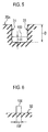
- Fig. 7 shows the relationship between the angle ⁇ and the heat transfer rate (index) in the groove portion 30.
- Fig. 8 shows the relationship between the coefficient applied to the length L of the protrusion portions 100 and the heat transfer rate in the groove portion 30.
- Fig. 9 shows the relationship between the coefficient applied to the groove depth D of the protrusion portions 100 and the heat transfer rate in the groove portion 30.
- Table 1 shows the relationship between the coefficient applied to the length L of the protrusion portions 100 and the heat transfer rate in the groove portion 30.
- the angle ⁇ is preferably set to 10 degrees to 60 degrees. If the angle ⁇ is smaller than 10 degrees, the flow of the running wind WD becomes very weak due to an acute angle portion formed by the protrusion portions 100 and the sidewall 31 (or the sidewall 33), and effective heat radiation from the tread portion 20 is not expected. Further, such a protrusion portions 100 are difficult to make. On the other hand, if the angle ⁇ exceeds 60 degrees, the effect of changing the running wind WD to a spiral flow is decreased. Thus, the air volume passing through the groove bottom 32 decreases, and effective heat radiation from the tread portion 20 is not expected. [Table 1] Examples marked with a "*" are included by way of reference.
- the coefficient applied to the length L is set to 0.75 to 10.00. If the coefficient is smaller than 1.25, the number of protrusion portions 100 provided in the groove portion 30 is too large. Thus, the speed of the running wind WD remarkably decreases, and effective heat radiation from the tread portion 20 is not expected. On the other hand, if the coefficient exceeds 10.00, the effect of changing the running wind ED to a spiral flow is decreased. Thus, the air volume passing through the groove bottom 32 decreases, and effective heat radiation from the tread portion 20 is not expected.
- the coefficient to be applied to the length L is larger than 1.25.
- the coefficient to be applied to the length L is preferably 1.5 or larger, and more preferably, 2.0 or larger.
- the coefficient to be applied to the groove depth D is preferably larger than 0.03, and 0.40 or smaller. If the coefficient is 0.03 or smaller, the height of the protrusion portions 100 in the groove portion 30 is too small. Thus, the effect of changing the running wind WD to a spiral flow is decreased, and effective heat radiation from the tread portion 20 is not expected. On the other hand, if the coefficient exceeds 0.400, the running wind WD can be changed to a spiral flow, but the running wind WD hardly reaches the groove bottom 32, and effective heat radiation from the tread portion 20 is not expected.
- a plurality of protrusion portions 100 are provided in the groove bottom 32 of the groove portion, and the protrusion portions 100 are continuous from one widewall 31 forming the groove portion 30 to the other sidewall 33.
- the protrusion portions 100 are obliquely provided so as to have the angle ⁇ with respect to the groove center line WL.
- the running wind WD passes beyond such a protrusion portions 100, the running wind WD changes to a spiral (swirl-like) flow, and the passing speed of the running wind ED increases.
- the air volume of the running wind WD passing through the groove bottom 32 increases, and heat radiation from the tread portion 20 is accelerated.
- a temperature increase of the tread portion 20 due to vehicle running can be effectively suppressed.
- the groove bottom 32 is flat at least in the width of 0.2W, the flow of the running wind WD passing through the groove bottom 32 is not disturbed, and a temperature increase of the tread portion 20 can be more effectively supressed.
- the groove portion 30 extends to be parallel to the tire circumferential direction, but the groove portion 30 may not extend to be parallel to the tire circumferential direction.
- the groove portion 30 may not be parallel to the tire circumferential direction.
- the groove portion 30 may not be linear, and for example, may be curved toward outside in the tread width direction, or may be zigzagged. When the groove portion 30 is zigzagged, it is preferably shaped not to decrease the speed of the running wind WD.
- the shape of the protrusion portions 100 may not be flat, and for example, may be wave-shaped in the tread surface view, or may be shaped thicker in the portion near the groove center line WL and thinner toward the sidewall 31 and sidewall 33 (or vice versa).
- Figs. 10 (a) to (g) show modifications of the cross-sectional shape of the protrusion portions 100. As shown in Figs. 10 (a) to (g) , the cross-sectional shape of the protrusion portions 100 may not be flat in the upper end (as in Fig. 6 ).
- angle ⁇ , the groove depth D, and the groove width W may not satisfy the conditions defined In the present embodiment described above.
- the present invention can provide a tire that can effectively suppress a temperature increase of a tread portion due to vehicle running.
Claims (7)
- Reifen (10), bei dem ein Rillenteil (30), der sich in einer Umfangsrichtung des Reifens erstreckt, in einem Profilteil (20) gebildet ist, wobei:an einem Rillenboden (32) des Rillenteils (30) eine Vielzahl von Vorsprungsteilen (100) angeordnet ist,sich die Vorsprungsteile (100) von einer Seitenwand (31), die den Rillenteil (30) bildet, zu der anderen Seitenwand (33) erstreckt, die der einen Seitenwand (31) gegenüberliegt,die Vorsprungsteile (100) in einem bestimmten Intervall im Rillenteil (30) angeordnet sind; unddadurch gekennzeichnet, dass in einer Ansicht der Profiloberfläche des Reifens (10) das Verhältnis 1,25L<P≦10L erfüllt ist, wenn die Länge der Vorsprungsteile (100) entlang der Rillenmittellinie (WL) L ist und das bestimmte Intervall P ist.
- Reifen (10) nach Anspruch 1, wobei ein Winkel θ 10 bis 60 Grad beträgt, wobei der Winkel in der Ansicht der Profiloberfläche des Reifens (10) zwischen einer angeordneten Richtung der Vorsprungsteile (100) und einer Rillenmittellinie (WL) gebildet wird, die durch die Mitte des Rillenteils (30) in Breitenrichtung verläuft, und an einer Seite gebildet wird, die einer Rotationsrichtung des Reifens (10) entgegengesetzt angeordnet ist.
- Reifen (10) nach Anspruch 1 oder 2, wobei das Verhältnis 0,03D<H≦0,4D erfüllt ist, wenn die Höhe der Vorsprungsteile (100) vom Rillenboden (32) H ist und die Tiefe von einer Profiloberfläche (20a) des Rillenteils (30) zum Rillenboden (32) D ist.
- Reifen (10) nach einem der Ansprüche 1 bis 3, wobei der Rillenboden (32) mindestens in der Breite von 0,2W flach ist, wenn die Rillenbreite des Rillenteils (30) W ist.
- Reifen (10) nach einem der Ansprüche 1 bis 4, wobei der Rillenteil (30) an einer Stelle gebildet ist, die eine Reifenäquatorlinie (CL) einschließt.
- Reifen (10) nach einem der Ansprüche 1 bis 5, wobei das Verhältnis DC/OD≥0,015 erfüllt ist, wenn ein Außendurchmesser des Reifens OD ist und eine Gummidicke eines Profilteils (20) an einer Stelle einer Reifenäquatorlinie (CL) DC ist.
- Reifen (10) nach einem der Ansprüche 1 bis 7, wobei die Vorsprungsteile (100) kontinuierlich von der einen Seitenwand (31) zu der anderen Seitenwand (33) angeordnet sind.
Applications Claiming Priority (3)
| Application Number | Priority Date | Filing Date | Title |
|---|---|---|---|
| JP2010293382 | 2010-12-28 | ||
| JP2010293377 | 2010-12-28 | ||
| PCT/JP2011/080030 WO2012090917A1 (ja) | 2010-12-28 | 2011-12-26 | タイヤ |
Publications (3)
| Publication Number | Publication Date |
|---|---|
| EP2660079A1 EP2660079A1 (de) | 2013-11-06 |
| EP2660079A4 EP2660079A4 (de) | 2014-10-22 |
| EP2660079B1 true EP2660079B1 (de) | 2016-08-03 |
Family
ID=46383021
Family Applications (1)
| Application Number | Title | Priority Date | Filing Date |
|---|---|---|---|
| EP11853086.4A Not-in-force EP2660079B1 (de) | 2010-12-28 | 2011-12-26 | Reifen |
Country Status (7)
| Country | Link |
|---|---|
| US (1) | US20130276947A1 (de) |
| EP (1) | EP2660079B1 (de) |
| JP (1) | JP5650761B2 (de) |
| CN (1) | CN103260903B (de) |
| BR (1) | BR112013014967B1 (de) |
| ES (1) | ES2592516T3 (de) |
| WO (1) | WO2012090917A1 (de) |
Families Citing this family (5)
| Publication number | Priority date | Publication date | Assignee | Title |
|---|---|---|---|---|
| JP5580369B2 (ja) * | 2012-07-04 | 2014-08-27 | 株式会社ブリヂストン | タイヤ |
| JP6031400B2 (ja) * | 2013-04-12 | 2016-11-24 | 株式会社ブリヂストン | 航空機用タイヤ |
| JP6243233B2 (ja) * | 2014-01-17 | 2017-12-06 | 株式会社ブリヂストン | タイヤ |
| JP6603470B2 (ja) * | 2015-04-10 | 2019-11-06 | 株式会社ブリヂストン | タイヤ |
| JP6803375B2 (ja) * | 2016-03-28 | 2020-12-23 | 株式会社ブリヂストン | タイヤ |
Family Cites Families (18)
| Publication number | Priority date | Publication date | Assignee | Title |
|---|---|---|---|---|
| JP3057381B2 (ja) * | 1991-04-11 | 2000-06-26 | 横浜ゴム株式会社 | 乗用車用空気入りラジアルタイヤ |
| JP2992466B2 (ja) * | 1995-02-24 | 1999-12-20 | 住友ゴム工業株式会社 | 空気入りタイヤ |
| JP2001253211A (ja) * | 2000-01-07 | 2001-09-18 | Bridgestone Corp | 空気入りラジアルタイヤ |
| EP1120296B1 (de) * | 2000-01-26 | 2006-09-27 | Bridgestone Corporation | Luftreifen |
| JP3493177B2 (ja) * | 2000-12-19 | 2004-02-03 | 住友ゴム工業株式会社 | 空気入りタイヤ |
| US7281555B2 (en) * | 2001-06-07 | 2007-10-16 | Bridgestone Corporation | Off-the-road tire |
| JP2003205704A (ja) * | 2002-01-09 | 2003-07-22 | Ohtsu Tire & Rubber Co Ltd :The | 空気入りタイヤ |
| EP1568514A4 (de) * | 2002-11-26 | 2010-12-29 | Yokohama Rubber Co Ltd | Luftreifen |
| JP4437888B2 (ja) * | 2003-01-24 | 2010-03-24 | 株式会社ブリヂストン | 空気入りタイヤ |
| US7329110B2 (en) * | 2003-05-13 | 2008-02-12 | Bridgestone Corporation | Tire vulcanizing mold and pneumatic tire |
| US7004216B2 (en) * | 2003-12-11 | 2006-02-28 | The Goodyear Tire & Rubber Company | Tire tread including spaced projections in base of groove |
| CN101890880B (zh) * | 2006-01-20 | 2013-09-18 | 横滨橡胶株式会社 | 充气轮胎 |
| EP1998814A4 (de) * | 2006-05-11 | 2010-06-16 | Novavax Inc | Neuartige impfstoffe gegen influenza m2 |
| DE102006031779B4 (de) * | 2006-07-10 | 2013-09-26 | Continental Reifen Deutschland Gmbh | Laufstreifenprofil eines Fahrzeugreifens |
| EP2644409B1 (de) * | 2007-02-09 | 2014-12-24 | Bridgestone Corporation | Luftreifen |
| ES2571030T3 (es) * | 2007-03-12 | 2016-05-23 | Bridgestone Corp | Neumático |
| JP5258210B2 (ja) * | 2007-06-05 | 2013-08-07 | 株式会社ブリヂストン | 空気入りタイヤ |
| JP5186203B2 (ja) * | 2007-12-28 | 2013-04-17 | 株式会社ブリヂストン | 空気入りタイヤ |
-
2011
- 2011-12-26 CN CN201180060750.2A patent/CN103260903B/zh not_active Expired - Fee Related
- 2011-12-26 ES ES11853086.4T patent/ES2592516T3/es active Active
- 2011-12-26 JP JP2012550928A patent/JP5650761B2/ja not_active Expired - Fee Related
- 2011-12-26 US US13/994,215 patent/US20130276947A1/en not_active Abandoned
- 2011-12-26 WO PCT/JP2011/080030 patent/WO2012090917A1/ja active Application Filing
- 2011-12-26 BR BR112013014967-1A patent/BR112013014967B1/pt active IP Right Grant
- 2011-12-26 EP EP11853086.4A patent/EP2660079B1/de not_active Not-in-force
Also Published As
| Publication number | Publication date |
|---|---|
| WO2012090917A1 (ja) | 2012-07-05 |
| CN103260903A (zh) | 2013-08-21 |
| CN103260903B (zh) | 2015-10-21 |
| JPWO2012090917A1 (ja) | 2014-06-05 |
| BR112013014967A2 (pt) | 2016-09-13 |
| JP5650761B2 (ja) | 2015-01-07 |
| EP2660079A4 (de) | 2014-10-22 |
| BR112013014967B1 (pt) | 2021-07-20 |
| EP2660079A1 (de) | 2013-11-06 |
| ES2592516T3 (es) | 2016-11-30 |
| US20130276947A1 (en) | 2013-10-24 |
Similar Documents
| Publication | Publication Date | Title |
|---|---|---|
| EP2660079B1 (de) | Reifen | |
| WO2012018128A1 (ja) | タイヤ | |
| EP2896513B1 (de) | Reifen für Baufahrzeug | |
| WO2009107436A1 (ja) | 空気入りタイヤ | |
| EP2974888B1 (de) | Luftreifen | |
| JP5795625B2 (ja) | タイヤ | |
| EP2871072B1 (de) | Reifen | |
| US20160052346A1 (en) | Tread Kerf of Snow Tire | |
| JPWO2014167990A1 (ja) | 空気入りタイヤ | |
| EP3718792A1 (de) | Luftreifen | |
| EP2689940A1 (de) | Luftreifen | |
| JP5799043B2 (ja) | 空気入りタイヤ | |
| US20180201070A1 (en) | Construction vehicle tire | |
| EP2974886B1 (de) | Luftreifen | |
| JP2011183993A (ja) | 空気入りタイヤ | |
| EP2631088B1 (de) | Schwerlastfahrzeugreifen | |
| JP2006182179A (ja) | 空気入りタイヤ | |
| WO2017204353A1 (ja) | 重荷重用タイヤ | |
| JP2011225105A (ja) | 空気入りタイヤ | |
| JP2002019421A (ja) | 空気入りタイヤ | |
| EP3281807B1 (de) | Reifen | |
| JP5985005B2 (ja) | 空気入りタイヤ | |
| JP2021041821A (ja) | 重荷重用空気入りタイヤ | |
| JP2009001103A (ja) | 空気入りタイヤ | |
| JP2014213725A (ja) | 航空機用タイヤ |
Legal Events
| Date | Code | Title | Description |
|---|---|---|---|
| PUAI | Public reference made under article 153(3) epc to a published international application that has entered the european phase |
Free format text: ORIGINAL CODE: 0009012 |
|
| 17P | Request for examination filed |
Effective date: 20130614 |
|
| AK | Designated contracting states |
Kind code of ref document: A1 Designated state(s): AL AT BE BG CH CY CZ DE DK EE ES FI FR GB GR HR HU IE IS IT LI LT LU LV MC MK MT NL NO PL PT RO RS SE SI SK SM TR |
|
| DAX | Request for extension of the european patent (deleted) | ||
| A4 | Supplementary search report drawn up and despatched |
Effective date: 20140918 |
|
| RIC1 | Information provided on ipc code assigned before grant |
Ipc: B60C 11/13 20060101ALI20140912BHEP Ipc: B60C 11/04 20060101AFI20140912BHEP |
|
| GRAP | Despatch of communication of intention to grant a patent |
Free format text: ORIGINAL CODE: EPIDOSNIGR1 |
|
| INTG | Intention to grant announced |
Effective date: 20160314 |
|
| RIN1 | Information on inventor provided before grant (corrected) |
Inventor name: OOGANE, SHUN |
|
| GRAS | Grant fee paid |
Free format text: ORIGINAL CODE: EPIDOSNIGR3 |
|
| GRAA | (expected) grant |
Free format text: ORIGINAL CODE: 0009210 |
|
| AK | Designated contracting states |
Kind code of ref document: B1 Designated state(s): AL AT BE BG CH CY CZ DE DK EE ES FI FR GB GR HR HU IE IS IT LI LT LU LV MC MK MT NL NO PL PT RO RS SE SI SK SM TR |
|
| REG | Reference to a national code |
Ref country code: GB Ref legal event code: FG4D |
|
| REG | Reference to a national code |
Ref country code: CH Ref legal event code: EP Ref country code: AT Ref legal event code: REF Ref document number: 817079 Country of ref document: AT Kind code of ref document: T Effective date: 20160815 |
|
| REG | Reference to a national code |
Ref country code: IE Ref legal event code: FG4D |
|
| REG | Reference to a national code |
Ref country code: DE Ref legal event code: R096 Ref document number: 602011028887 Country of ref document: DE |
|
| REG | Reference to a national code |
Ref country code: ES Ref legal event code: FG2A Ref document number: 2592516 Country of ref document: ES Kind code of ref document: T3 Effective date: 20161130 |
|
| REG | Reference to a national code |
Ref country code: NL Ref legal event code: MP Effective date: 20160803 |
|
| REG | Reference to a national code |
Ref country code: LT Ref legal event code: MG4D |
|
| REG | Reference to a national code |
Ref country code: FR Ref legal event code: PLFP Year of fee payment: 6 |
|
| REG | Reference to a national code |
Ref country code: AT Ref legal event code: MK05 Ref document number: 817079 Country of ref document: AT Kind code of ref document: T Effective date: 20160803 |
|
| PG25 | Lapsed in a contracting state [announced via postgrant information from national office to epo] |
Ref country code: HR Free format text: LAPSE BECAUSE OF FAILURE TO SUBMIT A TRANSLATION OF THE DESCRIPTION OR TO PAY THE FEE WITHIN THE PRESCRIBED TIME-LIMIT Effective date: 20160803 Ref country code: FI Free format text: LAPSE BECAUSE OF FAILURE TO SUBMIT A TRANSLATION OF THE DESCRIPTION OR TO PAY THE FEE WITHIN THE PRESCRIBED TIME-LIMIT Effective date: 20160803 Ref country code: NO Free format text: LAPSE BECAUSE OF FAILURE TO SUBMIT A TRANSLATION OF THE DESCRIPTION OR TO PAY THE FEE WITHIN THE PRESCRIBED TIME-LIMIT Effective date: 20161103 Ref country code: IS Free format text: LAPSE BECAUSE OF FAILURE TO SUBMIT A TRANSLATION OF THE DESCRIPTION OR TO PAY THE FEE WITHIN THE PRESCRIBED TIME-LIMIT Effective date: 20161203 Ref country code: NL Free format text: LAPSE BECAUSE OF FAILURE TO SUBMIT A TRANSLATION OF THE DESCRIPTION OR TO PAY THE FEE WITHIN THE PRESCRIBED TIME-LIMIT Effective date: 20160803 Ref country code: LT Free format text: LAPSE BECAUSE OF FAILURE TO SUBMIT A TRANSLATION OF THE DESCRIPTION OR TO PAY THE FEE WITHIN THE PRESCRIBED TIME-LIMIT Effective date: 20160803 Ref country code: RS Free format text: LAPSE BECAUSE OF FAILURE TO SUBMIT A TRANSLATION OF THE DESCRIPTION OR TO PAY THE FEE WITHIN THE PRESCRIBED TIME-LIMIT Effective date: 20160803 |
|
| PG25 | Lapsed in a contracting state [announced via postgrant information from national office to epo] |
Ref country code: LV Free format text: LAPSE BECAUSE OF FAILURE TO SUBMIT A TRANSLATION OF THE DESCRIPTION OR TO PAY THE FEE WITHIN THE PRESCRIBED TIME-LIMIT Effective date: 20160803 Ref country code: AT Free format text: LAPSE BECAUSE OF FAILURE TO SUBMIT A TRANSLATION OF THE DESCRIPTION OR TO PAY THE FEE WITHIN THE PRESCRIBED TIME-LIMIT Effective date: 20160803 Ref country code: SE Free format text: LAPSE BECAUSE OF FAILURE TO SUBMIT A TRANSLATION OF THE DESCRIPTION OR TO PAY THE FEE WITHIN THE PRESCRIBED TIME-LIMIT Effective date: 20160803 Ref country code: GR Free format text: LAPSE BECAUSE OF FAILURE TO SUBMIT A TRANSLATION OF THE DESCRIPTION OR TO PAY THE FEE WITHIN THE PRESCRIBED TIME-LIMIT Effective date: 20161104 Ref country code: PT Free format text: LAPSE BECAUSE OF FAILURE TO SUBMIT A TRANSLATION OF THE DESCRIPTION OR TO PAY THE FEE WITHIN THE PRESCRIBED TIME-LIMIT Effective date: 20161205 Ref country code: PL Free format text: LAPSE BECAUSE OF FAILURE TO SUBMIT A TRANSLATION OF THE DESCRIPTION OR TO PAY THE FEE WITHIN THE PRESCRIBED TIME-LIMIT Effective date: 20160803 |
|
| PG25 | Lapsed in a contracting state [announced via postgrant information from national office to epo] |
Ref country code: EE Free format text: LAPSE BECAUSE OF FAILURE TO SUBMIT A TRANSLATION OF THE DESCRIPTION OR TO PAY THE FEE WITHIN THE PRESCRIBED TIME-LIMIT Effective date: 20160803 Ref country code: RO Free format text: LAPSE BECAUSE OF FAILURE TO SUBMIT A TRANSLATION OF THE DESCRIPTION OR TO PAY THE FEE WITHIN THE PRESCRIBED TIME-LIMIT Effective date: 20160803 |
|
| REG | Reference to a national code |
Ref country code: DE Ref legal event code: R097 Ref document number: 602011028887 Country of ref document: DE |
|
| PG25 | Lapsed in a contracting state [announced via postgrant information from national office to epo] |
Ref country code: SM Free format text: LAPSE BECAUSE OF FAILURE TO SUBMIT A TRANSLATION OF THE DESCRIPTION OR TO PAY THE FEE WITHIN THE PRESCRIBED TIME-LIMIT Effective date: 20160803 Ref country code: BG Free format text: LAPSE BECAUSE OF FAILURE TO SUBMIT A TRANSLATION OF THE DESCRIPTION OR TO PAY THE FEE WITHIN THE PRESCRIBED TIME-LIMIT Effective date: 20161103 Ref country code: CZ Free format text: LAPSE BECAUSE OF FAILURE TO SUBMIT A TRANSLATION OF THE DESCRIPTION OR TO PAY THE FEE WITHIN THE PRESCRIBED TIME-LIMIT Effective date: 20160803 Ref country code: SK Free format text: LAPSE BECAUSE OF FAILURE TO SUBMIT A TRANSLATION OF THE DESCRIPTION OR TO PAY THE FEE WITHIN THE PRESCRIBED TIME-LIMIT Effective date: 20160803 Ref country code: DK Free format text: LAPSE BECAUSE OF FAILURE TO SUBMIT A TRANSLATION OF THE DESCRIPTION OR TO PAY THE FEE WITHIN THE PRESCRIBED TIME-LIMIT Effective date: 20160803 Ref country code: BE Free format text: LAPSE BECAUSE OF FAILURE TO SUBMIT A TRANSLATION OF THE DESCRIPTION OR TO PAY THE FEE WITHIN THE PRESCRIBED TIME-LIMIT Effective date: 20160803 |
|
| PLBE | No opposition filed within time limit |
Free format text: ORIGINAL CODE: 0009261 |
|
| STAA | Information on the status of an ep patent application or granted ep patent |
Free format text: STATUS: NO OPPOSITION FILED WITHIN TIME LIMIT |
|
| 26N | No opposition filed |
Effective date: 20170504 |
|
| REG | Reference to a national code |
Ref country code: CH Ref legal event code: PL |
|
| GBPC | Gb: european patent ceased through non-payment of renewal fee |
Effective date: 20161226 |
|
| PG25 | Lapsed in a contracting state [announced via postgrant information from national office to epo] |
Ref country code: SI Free format text: LAPSE BECAUSE OF FAILURE TO SUBMIT A TRANSLATION OF THE DESCRIPTION OR TO PAY THE FEE WITHIN THE PRESCRIBED TIME-LIMIT Effective date: 20160803 |
|
| PG25 | Lapsed in a contracting state [announced via postgrant information from national office to epo] |
Ref country code: MC Free format text: LAPSE BECAUSE OF FAILURE TO SUBMIT A TRANSLATION OF THE DESCRIPTION OR TO PAY THE FEE WITHIN THE PRESCRIBED TIME-LIMIT Effective date: 20160803 |
|
| REG | Reference to a national code |
Ref country code: IE Ref legal event code: MM4A |
|
| PG25 | Lapsed in a contracting state [announced via postgrant information from national office to epo] |
Ref country code: LU Free format text: LAPSE BECAUSE OF NON-PAYMENT OF DUE FEES Effective date: 20161226 Ref country code: LI Free format text: LAPSE BECAUSE OF NON-PAYMENT OF DUE FEES Effective date: 20161231 Ref country code: CH Free format text: LAPSE BECAUSE OF NON-PAYMENT OF DUE FEES Effective date: 20161231 |
|
| PG25 | Lapsed in a contracting state [announced via postgrant information from national office to epo] |
Ref country code: GB Free format text: LAPSE BECAUSE OF NON-PAYMENT OF DUE FEES Effective date: 20161226 Ref country code: IE Free format text: LAPSE BECAUSE OF NON-PAYMENT OF DUE FEES Effective date: 20161226 |
|
| REG | Reference to a national code |
Ref country code: FR Ref legal event code: PLFP Year of fee payment: 7 |
|
| PG25 | Lapsed in a contracting state [announced via postgrant information from national office to epo] |
Ref country code: HU Free format text: LAPSE BECAUSE OF FAILURE TO SUBMIT A TRANSLATION OF THE DESCRIPTION OR TO PAY THE FEE WITHIN THE PRESCRIBED TIME-LIMIT; INVALID AB INITIO Effective date: 20111226 Ref country code: CY Free format text: LAPSE BECAUSE OF FAILURE TO SUBMIT A TRANSLATION OF THE DESCRIPTION OR TO PAY THE FEE WITHIN THE PRESCRIBED TIME-LIMIT Effective date: 20160803 |
|
| PG25 | Lapsed in a contracting state [announced via postgrant information from national office to epo] |
Ref country code: MK Free format text: LAPSE BECAUSE OF FAILURE TO SUBMIT A TRANSLATION OF THE DESCRIPTION OR TO PAY THE FEE WITHIN THE PRESCRIBED TIME-LIMIT Effective date: 20160803 |
|
| PG25 | Lapsed in a contracting state [announced via postgrant information from national office to epo] |
Ref country code: MT Free format text: LAPSE BECAUSE OF NON-PAYMENT OF DUE FEES Effective date: 20161226 |
|
| PG25 | Lapsed in a contracting state [announced via postgrant information from national office to epo] |
Ref country code: AL Free format text: LAPSE BECAUSE OF FAILURE TO SUBMIT A TRANSLATION OF THE DESCRIPTION OR TO PAY THE FEE WITHIN THE PRESCRIBED TIME-LIMIT Effective date: 20160803 Ref country code: TR Free format text: LAPSE BECAUSE OF FAILURE TO SUBMIT A TRANSLATION OF THE DESCRIPTION OR TO PAY THE FEE WITHIN THE PRESCRIBED TIME-LIMIT Effective date: 20160803 |
|
| PGFP | Annual fee paid to national office [announced via postgrant information from national office to epo] |
Ref country code: IT Payment date: 20191230 Year of fee payment: 9 |
|
| PGFP | Annual fee paid to national office [announced via postgrant information from national office to epo] |
Ref country code: ES Payment date: 20200121 Year of fee payment: 9 |
|
| PG25 | Lapsed in a contracting state [announced via postgrant information from national office to epo] |
Ref country code: IT Free format text: LAPSE BECAUSE OF NON-PAYMENT OF DUE FEES Effective date: 20201226 |
|
| PGFP | Annual fee paid to national office [announced via postgrant information from national office to epo] |
Ref country code: DE Payment date: 20211210 Year of fee payment: 11 Ref country code: FR Payment date: 20211224 Year of fee payment: 11 |
|
| REG | Reference to a national code |
Ref country code: ES Ref legal event code: FD2A Effective date: 20220412 |
|
| PG25 | Lapsed in a contracting state [announced via postgrant information from national office to epo] |
Ref country code: ES Free format text: LAPSE BECAUSE OF NON-PAYMENT OF DUE FEES Effective date: 20201227 |
|
| REG | Reference to a national code |
Ref country code: DE Ref legal event code: R119 Ref document number: 602011028887 Country of ref document: DE |
|
| PG25 | Lapsed in a contracting state [announced via postgrant information from national office to epo] |
Ref country code: DE Free format text: LAPSE BECAUSE OF NON-PAYMENT OF DUE FEES Effective date: 20230701 |
|
| PG25 | Lapsed in a contracting state [announced via postgrant information from national office to epo] |
Ref country code: FR Free format text: LAPSE BECAUSE OF NON-PAYMENT OF DUE FEES Effective date: 20221231 |