EP2659810A1 - Standfuß eines Gerätes, insbesondere einer Tisch-Küchenmaschine - Google Patents
Standfuß eines Gerätes, insbesondere einer Tisch-Küchenmaschine Download PDFInfo
- Publication number
- EP2659810A1 EP2659810A1 EP13166030.0A EP13166030A EP2659810A1 EP 2659810 A1 EP2659810 A1 EP 2659810A1 EP 13166030 A EP13166030 A EP 13166030A EP 2659810 A1 EP2659810 A1 EP 2659810A1
- Authority
- EP
- European Patent Office
- Prior art keywords
- extension
- stand
- soft tissue
- particular according
- shell
- Prior art date
- Legal status (The legal status is an assumption and is not a legal conclusion. Google has not performed a legal analysis and makes no representation as to the accuracy of the status listed.)
- Granted
Links
Images



Classifications
-
- A—HUMAN NECESSITIES
- A47—FURNITURE; DOMESTIC ARTICLES OR APPLIANCES; COFFEE MILLS; SPICE MILLS; SUCTION CLEANERS IN GENERAL
- A47J—KITCHEN EQUIPMENT; COFFEE MILLS; SPICE MILLS; APPARATUS FOR MAKING BEVERAGES
- A47J43/00—Implements for preparing or holding food, not provided for in other groups of this subclass
- A47J43/04—Machines for domestic use not covered elsewhere, e.g. for grinding, mixing, stirring, kneading, emulsifying, whipping or beating foodstuffs, e.g. power-driven
- A47J43/07—Parts or details, e.g. mixing tools, whipping tools
- A47J43/0716—Parts or details, e.g. mixing tools, whipping tools for machines with tools driven from the lower side
- A47J43/0722—Mixing, whipping or cutting tools
-
- A—HUMAN NECESSITIES
- A47—FURNITURE; DOMESTIC ARTICLES OR APPLIANCES; COFFEE MILLS; SPICE MILLS; SUCTION CLEANERS IN GENERAL
- A47B—TABLES; DESKS; OFFICE FURNITURE; CABINETS; DRAWERS; GENERAL DETAILS OF FURNITURE
- A47B91/00—Feet for furniture in general
- A47B91/04—Elastic supports
Definitions
- the invention relates to a base of a device, in particular a table-top food processor, wherein the device has a housing with a conventional installation downwardly projecting projection which rests on a stand forming a standing part by means of a soft tissue, wherein the soft tissue in an open-topped shell portion of the stand part is added.
- Feet especially for food processors, are known. These are for supporting the device, in particular the food processor, on a surface, in particular on a table surface, designed, more preferably via the base in the device caused vibrations, especially when the device has a drive motor for other purposes, are damped. It should not come to dislocations or even jumps of the device relative to the surface.
- a vibration damper for transformers in which a vibration damping provided for soft tissue between two oppositely open shell portions of the stand part or a frame extension is added.
- the soft tissue forms over an intermediate portion alone a cross-sectional area of the base.
- the invention has the object to provide a base of a device, in particular a table-top kitchen appliance, which provides a favorable damping possibility in an advantageous structure.
- a possible solution of the problem is given according to a first idea of the invention in a base, in which the extension extends into a lateral overlap to the shell portion.
- the soft tissue does not form a single cross-section on any intermediate section of the pedestal. Rather, the extension and the shell section, directed in opposite directions, engage each other in lateral overlap. As a result, a favorable possibility of supporting and receiving the soft tissue is given.
- it follows that the soft tissue is in a protected position with respect to external attacks. As a result, the soft tissue is usually not visible.
- the standing part has a mounting extension which is connected to the extension which extends downwardly from the housing for holding the stand part to the extension .
- the support extension can also enforce the soft tissue at least partially. Preferably, it completely penetrates the soft tissue.
- the holder of the support extension to the extension of the housing also provides a convenient mounting option of the stand part. It may be realized, for example, as further explained below, that the attachment in the course of assembly between the support extension and the extension of the housing interior can be made forth. This may prove to be beneficial in the course of a production of such a device "from bottom to top".
- the soft tissue is preferably a foam part, more preferably a polyurethane foam part. It may be an open-pore or closed-cell foam, with closed-cell foam, in particular in connection with a food processor, having advantages.
- the soft tissue is preferably set to be softer overall, in particular in the area acted upon by the extension, than the standing part. It accordingly has a lower Shore hardness than the stand part.
- the upwardly open shell section forms a preferably peripheral boundary of the deflection space provided by the shell section for the soft tissue.
- the soft tissue can be compressed during movements of the extension relative to the standing part in the covering area to the extension between the extension and the wall of the shell portion.
- the soft tissue is preferably arranged captive in the shell section.
- the shell portion may be formed integrally with the stand part.
- the bottom surface of the shell portion may preferably directly form the standing surface. With regard to an indirect formation of the standing surface, this may be achieved, for example, by arranging a part which sits indirectly on the floor, for example an elastomer part, below the floor.
- the soft tissue is adjusted in terms of its Shore hardness so that the device-side extension at the usual maximum weight of the device or in particular the food processor does not compress the soft tissue in such a way that results in a virtually rigid transition to the stand part. Rather, the hardness is chosen so that even then can still adjust an elastic compression.
- the extension itself is harder with respect to the soft part, in particular by forming the extension made of hard plastic or metal.
- the standing surface forming, more preferably at the same time the shell portion forming standing part is set harder compared to the soft part, this also preferred as a result of embodiment of the stand part as a hard plastic part or metal part, for example.
- the extension is received in the shell portion horizontally and vertically movable.
- the housing-side extension is in particular transversely to a vertical direction, ie, preferably according to a preferred manner in a horizontal direction relative to the standing part forming, further suitably the base area offering shell portion movably mounted.
- this alone can be achieved with a corresponding horizontal movement elastic deformation of the soft tissue in this horizontal direction.
- a bulging in the soft tissue may occur during compression.
- the bead can also be pressed in again due to the elasticity of the soft tissue.
- This is not necessarily a vertical movement of the device connected. Rather, it can even set itself to compensate for the effects, so that it So practically does not come to a dipping of the device so far in the usual horizontal movements.
- the movement of the extension in particular in the horizontal direction relative to the base part, generates a return spring force correspondingly in the soft tissue which is thus subjected to deformation, this also under relative displacement of the extension to the soft tissue.
- the vertical mobility of the extension in the shell portion is carried out vertically downwards, preferably also against a return spring force of the soft tissue, which is compressed accordingly in a weight application or vertical downward displacement of the extension.
- the rotating agitator can resist high resistance due to the dough's toughness. This can also lead to jerky movements at high drive torque of the agitator driving motor.
- a food processor is preferably supported by a plurality of feet, in particular as described here.
- the energy introduced into the base in a shock or swing manner is converted into friction between the associated and superimposed surfaces of the extension and the soft tissue, this also preferably in relation to the associated and superimposed surfaces of the soft tissue and the standing part.
- the horizontal mobility of the extension in the shell portion is preferably limited. This is further preferred by the shell wall of the shell section located in overlap with the extension. In addition or, where appropriate, as an alternative, this limitation can also be set by means of material placement in the region of the soft tissue as a result of a customary combined vertical and horizontal loading by means of the housing-side extension.
- the extension for cooperation with the soft tissue in terms of horizontal movement with a vertical portion of the soft tissue is in coverage. Accordingly, in a horizontal movement of the extension preferably a compression of the soft tissue according to preferably blunt loading of the soft tissue in the region of a vertical portion thereof is achieved.
- the extension preferably has a corresponding section for cooperation with the vertical section of the soft tissue, which section at the same time also provides the support of the extension in the vertical direction on the soft tissue in one embodiment.
- a separate extension portion is provided for the vertical support of the extension on the soft tissue, more preferably a portion which is in relation to a vertical section extends through the extension with horizontal distance outside of the soft tissue vertical portion associated extension portion.
- the soft tissue is at least partially circular in shape, more preferably, in particular, the soft tissue surface defining the circular ring opening forms the vertical portion for cooperation with an extension portion in a horizontal movement. It proves to be advantageous, in particular, this, with the vertical portion of the soft tissue, further in particular the cooperating with the circular ring opening limiting surface portion of the extension with respect to its outer wall at least partially annular. If a separate extension section is provided for cooperation with the soft tissue during a vertical movement, then this preferably runs concentrically to the section of the extension which interacts with the circular ring opening of the soft tissue.
- the stand part further preferably has a vertically extending holding portion which is in holding connection, which is preferably realized as a positive connection, to the extension.
- a vertically extending holding portion which is in holding connection, which is preferably realized as a positive connection, to the extension.
- the standing part is captively connected to the extension, but preferably also the soft tissue received in the shell section, for example according to a circular or annular, the support extension surrounding configuration.
- a table-top kitchen machine can thus be optionally raised and offset without loss of the stand part.
- the positive connection is in this case preferably designed so that a vertical mobility of the extension is given relative to the stand part, wherein more preferably the positive connection between extension and standteil workedem support portion represents a limitation of the vertical mobility in one direction.
- the mounting portion is in this case further preferably designed as a pin passing through the extension vertically, more preferably in the form of a circular cylindrical pin.
- This pin is arranged growing out of the bottom of the dish in a further preferred annular arrangement of the shell wall of the stand part, further preferably correspondingly centrally receiving the vertical body axis of the stand part.
- the pin preferably penetrates the extension in the vertical direction, i. preferably parallel to a lowering direction of the extension connected to the food processor.
- the positive connection is preferably achieved by means of an overlapping disk, which further preferably cooperates with the journal as well as with a mating surface on the extension.
- the extension and the base part are preferably telescopically movable relative to one another via the pin, in particular along a vertical axis passing through both the extension and the base part.
- the extension is preferably at least partially tubular in its section located in overlap with the stationary part, in particular for the vertical throughput of the stand-side journal.
- the free inner diameter of the tube-like Standteil section is here selected to be greater than the outer diameter of the stand side spigot or greater than the largest Quererstreckungslick in the throughput area, whereby the relative horizontal mobility of the extension is achieved to the shell portion or to the stand part.
- the positive retention of the standing part is preferably provided on the extension.
- the material of the soft tissue and the overlap of the extension to the soft tissue is selected or adjusted so that with a displacement of 1 mm with respect to all resting on a base feet of the food processor (preferably: 4 feet) a restoring force of 5 N or more, up to preferably 15 N, more preferably about 10 N.
- the restoring force in particular of the soft tissues, increases disproportionately.
- a restoring force which corresponds to 2.1 to 3 times, more preferably approximately 2.5 times the reset value at 1 mm, preferably occurs.
- a restoring force of the soft parts of about 25 N results. Accordingly, a non-linear increase of the restoring force is provided.
- the soft tissue can, as already mentioned, consist of a foam. It can not only consist of an open-pore or closed-pore, but also of a mixed-pored foam.
- a polyurethane foam more preferably a mixed cellular polyurethane foam with partially closed and partially open pores.
- a soft tissue preferably has a tensile strength (minimum value according to DIN53571) of 0.5 to 1.5 N / mm 2 , more preferably 0.56 to 1.3 N / mm 2 . In a preferred embodiment, a draft of 0.78 N / mm 2 is provided.
- a soft tissue is adjusted so that, based on EN 826, a static modulus of elasticity of 0.05 to 1.3 N / mm 2 is established preferably 0.14 to 0.75 N / mm 2 .
- a dynamic elastic modulus according to DIN53513 of 0.3 to 1.8 N / mm 2 , more preferably 0.6 to 1.3 N / mm 2 is provided.
- FIG. 1 Shown and described is first with reference to Fig. 1 a food processor 1 with a mixing vessel receptacle 2 and a control panel 3.
- the food processor 1 is associated with a stirring bowl 4. This sits in the mixing vessel receptacle 2 a.
- the mixing pot 4 is associated with a stirring pot bottom an agitator provided, which is operated via a arranged in the kitchen machine 1 below the receptacle 2, not shown electric drive.
- the housing 5 of the food processor 1 is supported by support feet 6 on a surface, here a table surface 7.
- the support feet 6 are for this purpose attached to the underside of a housing bottom 8.
- the food processor 1 is suitable, inter alia, for the production of doughs.
- a high resistance is opposed to the rotating agitator by the dough's toughness.
- the required drive torque of the engine is supported, of course, during other engine operation, via the housing 5 and the support legs 6. If the dough ball is arranged unfavorably in the mixing vessel 4, the agitator may remain stuck in the dough for a short time. As a result, the torque is briefly increased. Even such a momentum shock is compensated by the support legs 6, so that the device does not jerky and jump around its center of gravity. In addition, vibrations or, in particular, vertical impacts in the direction of the table surface 7 are compensated for via the support feet 6.
- the movement of the housing 5 in the horizontal direction is allowed.
- the housing 5 can move relative to the support legs 6 or, as explained in more detail below, relative to a section of the support feet 6 in the horizontal plane.
- the possibly suddenly introduced energy is converted into friction and / or restoring and deformation energy.
- the support legs 6 are preferred on the Stand surface - here the table surface 7 - only sessile and prevented by friction against movement relative to the base.
- given by the configuration of the support legs 6 also relative vertical movements of the support feet 6 supported on the housing 5 in particular relative to a portion of the support legs 6.
- Each support leg 6 is designed essentially in two parts, wherein a part is fixed to the housing.
- This is an extension 9 which is molded on the housing side, in particular on the housing bottom side, and protrudes freely vertically downwards over the downwardly directed housing base surface.
- the extension 9 is preferably preferably rigidly connected above the housing bottom 8 to a weighing beam of a weighing device, which load beam in turn engages the housing, in particular the housing base 8, on the other end.
- the projection 9 is designed as a rigid part, more preferably according to one-piece, uniform material configuration together with the housing bottom 8. Accordingly, it may be in the extension 9 to a hard plastic or metal body, which further preferably with respect to a centrally passing through the extension 9 vertical axis x is rotationally symmetrical.
- an extension 9 is also alternatively provided, which can be fixed on the underside of the housing base 8, for example screwed.
- the housing-side projection 9 is seated substantially on a, a standing surface 10 forming stand part 11, which stand part 11 corresponding to substantially the second part of the support leg 6 forms.
- the extension 9 is substantially formed as a rotationally symmetrical hollow body, with a peripheral extension wall 12.
- a peripheral extension wall 12 In the through the extension wall 12 encompassed tube opening 13 is at a vertical distance to the vertical bottom free peripheral edge of the extension wall 12, a bottom 14 in one piece and preferably of the same material with the extension wall 12th moved in.
- a vertically concentric to the vertical axis x arranged tube portion 15 is integrally formed below the lower side, according to vertically down, the projecting vertically downwardly facing end face beyond the defined by the downwardly facing free edge of the extension wall 12 horizontal plane.
- the vertical distance c between the extending in a horizontal plane end face of the tube section 15 and the end edge of the extension wall 12 preferably corresponds to one fifth to one tenth, more preferably about one-eighth of the outer diameter d of the extension wall 12th
- the free radial distance e between the outer wall side of the tube section 15 and the inner wall side of the extension wall 12 further preferably corresponds to about a third to a half, more preferably about a quarter of the extension wall outer diameter d.
- the tube section 15 is centrally penetrated by a circular cylindrical opening 19, which also passes through the bottom 14 at the same time.
- the stand part 11 forms a vertically upwardly open shell portion 16, correspondingly has a more preferably circular disk-shaped shell bottom 17 and a peripheral shell wall 18.
- the shell wall 18 essentially corresponds to the vertical extension dimension of the opening 19 in the extension 9.
- the inner diameter f of the shell portion 16 preferably corresponds to 1.1 to 1.5, more preferably 1.2 to 1.4 times the outer diameter d of the extension wall 12, which in a like in Fig. 3 illustrated basic alignment circumferentially between the extension wall 12 and the shell wall 18, an annular gap 20 sets.
- a preferably circular cross-section pin 21 from.
- This is preferably arranged centrally and in one piece, formed of the same material with the shell portion 16.
- the diameter g is in this case selected smaller than the inner diameter h of the extension-side opening 19, wherein the pin 21 protrudes through the opening 19 with its pointing vertically upwards end face on the upward-facing plane of the extension bottom 14.
- a concentric arrangement of extension 9 and shell portion 16 or stand part 11 results between the pin 21 and the wall of the opening 19 a circumferential gap whose radial dimension is preferably equal to or greater than the radial dimension of the annular gap 20th
- the stand part 11 is held positively on the extension 9.
- an overlap disc 22 is provided which is centrally penetrated by the pin 21 and preferably rests on the upward-facing surface of the extension bottom 14.
- a above the overlap disc 22 wall outside on the pin 21 provided collar 23, preferably in the form of a snap ring or the like captivates the stand part 11 on the overlap plate 22 on the extension 9, while allowing a vertical mobility of the stand part 11 relative to the extension 9, starting from the illustration in FIG Fig. 3 to vertically above.
- a soft tissue 24 is provided. This is preferably designed annular and further preferably consists of a flexible foam.
- the soft tissue 24 sits in the shell section 16 on the shell bottom 17 and preferably has an outer diameter adapted to the inner diameter of the shell wall 18.
- the free inner diameter of the soft tissue 24 is further preferably adapted to the outer diameter of the extension-side tube portion 15, wherein more preferably, the circular ring inner diameter of the soft tissue 24 corresponds to about 1.01 to 1.1 times the tube section outer diameter.
- the soft tissue 24 is held in a preferred embodiment only by frictional or positive fit in the shell portion 16.
- a fastening in this regard is possible, for example, according to bonding.
- the vertical height of the soft tissue 24 further preferably corresponds to about half the height of the shell wall 18, wherein further vertical heights of the soft tissue 24 of preferably one fifth to two thirds of the shell wall height are possible.
- the arrangement is further preferably selected so that in an unloaded basic position as shown in FIG Fig. 3 the extension 9 is seated with the downwardly facing free edge edge of the extension wall 12 on the upwardly facing annular surface of the soft tissue 24, while the tube section 15 of the extension 9 is inserted into the ring opening of the soft tissue 24,
- This position is further preferred also the telescopic extension position of extension 9 and stand part 11, in which position the pin 21 with its collar 23 on the top of the overlap disc 22 is supported, which latter in turn preferably rests on the facing surface of the extension-side bottom 14.
- the soft tissue 24 is preferably adjusted in terms of hardness so that it is in a basic load (taking into account a maximum total weight of the food processor 1 and not activated agitator) preferably not or only slightly compressed on the extension wall 12.
- Fig. 5 shows pure horizontal load according to oscillations rather theoretical.
- a pure horizontal load corresponding to vibrations in the arrows a and b in Fig. 1 marked level, lead to a corresponding displacement of the extension 9 relative to the stand part 11, wherein the extension 9 leaves the common vertical axis x.
- the extension-side tube section 15 is supported on the associated vertical surface of the soft-tissue circular-ring opening, this further under corresponding at least partial compression of the soft-tissue material in the acted upon Zone. This also achieves a sufficient damping of the impact energy.
- the extension 9 is supported in a damped manner in all shock-relevant directions by the soft tissue 24, wherein the soft tissue 24 is preferably designed so that this, via the elastic restoring capabilities, the extension 9 in each case tends to the initial position Fig. 3 urges. Further, the hardness of the soft tissue 24 is selected so that at normal vertical shock loads, especially in proper operation of the food processor, ie continue with proper maximum filling of the stirring pot 4, the vertically downwardly facing free end face of the tube section 15 even in the maximum load a vertical distance to the adheres to the facing surface of the shell bottom 17.
- the shell bottom 17 is preferably provided on the underside with an elastomer part 25, preferably in the form of a rubberized base.
- the elastomer part 25 is fastened to the base part 11 on the underside, for example adhesively bonded, or alternatively produced together with the base part 11, for example in a two-component injection molding process.
- the downwardly facing surface of the elastomer part 25 correspondingly forms the base 10 for cooperation with, for example, the table surface 7.
- the base part 11 is friction-retained on the table surface 7 even in the case of impacts or vibrations introduced via the extension 9.
Landscapes
- Engineering & Computer Science (AREA)
- Mechanical Engineering (AREA)
- Food Science & Technology (AREA)
- Food-Manufacturing Devices (AREA)
Abstract
Description
- Die Erfindung betrifft einen Standfuß eines Gerätes, insbesondere einer Tisch-Küchenmaschine, wobei das Gerät ein Gehäuse mit einem bei üblicher Aufstellung nach unten abragenden Fortsatz aufweist, der auf einem eine Standfläche ausbildenden Standteil mittels eines Weichteils aufsitzt, wobei das Weichteil in einem oben offenen Schalenabschnitt des Standteils aufgenommen ist.
- Standfüße, insbesondere für Küchenmaschinen, sind bekannt. Diese sind zur Abstützung des Gerätes, insbesondere der Küchenmaschine, auf einer Fläche, insbesondere auf einer Tischfläche, ausgelegt, wobei weiter bevorzugt über den Standfuß in dem Gerät hervorgerufene Schwingungen, insbesondere wenn das Gerät zu anderen Zwecken einen Antriebsmotor aufweist, gedämpft werden. Es soll nicht zu Versetzungen oder gar Sprüngen des Gerätes relativ zu der Fläche kommen.
- Aus der
DE 29622725 U1 ist ein Schwingungsdämpfer für Transformatoren bekannt, bei welchem ein zur Schwingungsdämpfung vorgesehenes Weichteil zwischen zwei gegensinnig geöffneten Schalenabschnitten des Standteils beziehungsweise ein Gestell-Fortsatz aufgenommen ist. Das Weichteil bildet über einen Zwischenabschnitt allein eine Querschnittsfläche des Standfußes aus. - Ausgehend von dem genannten Stand der Technik beschäftigt sich die Erfindung mit der Aufgabe, einen Standfuß eines Gerätes, insbesondere einer Tisch-Küchenmaschine anzugeben, der bei vorteilhaftem Aufbau eine günstige Dämpfungsmöglichkeit erbringt.
- Eine mögliche Lösung der Aufgabe ist nach einem ersten Erfindungsgedanken bei einem Standfuß gegeben, bei dem der Fortsatz bis in eine seitliche Überdeckung zu dem Schalenabschnitt erstreckt. Das Weichteil bildet auf keinem Zwischenabschnitt des Standfußes einen alleinigen Querschnitt. Vielmehr fassen der Fortsatz und der Schalenabschnitt, gegensätzlich gerichtet, in seitlicher Überdeckung ineinander. Hierdurch ist eine günstige Möglichkeit der Abstützung und Aufnahme des Weichteils gegeben. Zudem ergibt sich, dass das Weichteil hinsichtlich Angriffen von außen in einer Geschütztlage ist. Das Weichteil ist auch hierdurch in der Regel nicht sichtbar.
- In alternativer oder ergänzender Weise, insbesondere auch unabhängig von dem vorstehend beschriebenen Merkmalskomplex, kann vorgesehen sein, dass das Standteil einen Halterungsfortsatz aufweist, der mit dem Fortsatz, der sich von dem Gehäuse aus nach unten erstreckt, zur Halterung des Standteils an dem Fortsatz verbunden ist. Der Halterungsfortsatz kann hierbei auch das Weichteil zumindest teilweise durchsetzen. Vorzugsweise durchsetzt er das Weichteil vollständig. Die Halterung des Halterungsfortsatzes an dem Fortsatz des Gehäuses erbringt auch eine günstige Montagemöglichkeit des Standteils. Es kann beispielsweise verwirklicht sein, wie nachstehend auch noch weiter erläutert, dass die Befestigung im Zuge des Zusammenbaus zwischen dem Halterungsfortsatz und dem Fortsatz vom Gehäuseinneren her vorgenommen werden kann. Dies kann sich etwa als günstig erweisen im Zuge einer Fertigung eines solchen Gerätes "von unten nach oben".
- Weitere Merkmale der Erfindung sind nachstehend, auch in der Figurenbeschreibung und der Zeichnung, oftmals in ihrer bevorzugten Zuordnung zum Gegenstand des Anspruches 1 oder zu Merkmalen weiterer Ansprüche erläutert. Sie können aber auch in einer Zuordnung zu nur einzelnen Merkmalen des Anspruches 1 oder des jeweiligen weiteren Anspruches oder jeweils unabhängig von Bedeutung sein.
- So handelt es sich bei dem Weichteil bevorzugt um ein Schaumstoffteil, weiter bevorzugt um ein Polyuretan-Schaumstoffteil. Es kann ein offenporiger oder geschlossenporiger Schaumstoff sein, wobei geschlossenporiger Schaumstoff, insbesondere im Zusammenhang bei einer Küchenmaschine, Vorzüge aufweist.
- Von Bedeutung ist auch, dass das Weichteil bevorzugt insgesamt, insbesondere in dem durch den Fortsatz beaufschlagten Bereich, weicher eingestellt ist als das Standteil. Es weist entsprechend eine geringere Shore-Härte als das Standteil auf.
- Der nach oben offene Schalenabschnitt bildet insbesondere eine bevorzugt umlaufende Begrenzung des durch den Schalenabschnitt gegebenen Ausweichraumes für das Weichteil. Das Weichteil kann bei Bewegungen des Fortsatzes relativ zu dem Standteil im Überdeckungsbereich zu dem Fortsatz zwischen dem Fortsatz und der Wand des Schalenabschnittes komprimiert werden.
- Das Weichteil ist bevorzugt unverlierbar in dem Schalenabschnitt angeordnet. Der Schalenabschnitt kann einteilig mit dem Standteil ausgebildet sein. Die Bodenfläche des Schalenabschnittes kann bevorzugt unmittelbar die Standfläche bilden. Im Hinblick auf eine mittelbare Bildung der Standfläche kann dies etwa dadurch gegeben sein, dass unterhalb des Bodens noch ein mittelbar auf dem Boden aufsitzendes Teil, beispielsweise ein Elastomerteil, angeordnet ist.
- Weiter bevorzugt ist das Weichteil hinsichtlich seiner Shore-Härte so eingestellt, dass der geräteseitige Fortsatz bei üblichem Maximalgewicht des Gerätes beziehungsweise insbesondere der Küchenmaschine das Weichteil nicht derart komprimiert, dass sich ein gleichsam starrer Übergang zu dem Standteil ergibt. Vielmehr ist die Härte so gewählt, dass auch dann immer noch sich ein elastisches Einfedern einstellen kann.
- Bevorzugt ist der Fortsatz selbst gegenüber dem Weichteil härter ausgebildet, insbesondere durch eine Ausbildung des Fortsatzes aus Hartkunststoff oder Metall. Auch das die Standfläche ausbildende, weiter bevorzugt zugleich den Schalenabschnitt ausformende Standteil ist gegenüber dem Weichteil härter eingestellt, dies auch bevorzugt zufolge Ausgestaltung des Standteils als Hartkunststoffteil oder beispielsweise Metallteil.
- In weiterer bevorzugter Ausgestaltung ist vorgesehen, dass der Fortsatz in dem Schalenabschnitt horizontal und vertikal beweglich aufgenommen ist. Zufolge dieser Ausgestaltung ist der gehäuseseitige Fortsatz insbesondere quer zu einer Vertikalrichtung, d.h. entsprechend bevorzugt in einer Horizontalrichtung gegenüber dem das Standteil ausbildenden, weiter entsprechend bevorzugt die Standfläche anbietenden Schalenabschnitt beweglich gelagert. In der Zusammenwirkung des Fortsatzes mit dem in dem Schalenabschnitt aufgenommenen Weichteil, soweit ein Aufsitzen des Fortsatzes auf dem Weichteil gegeben ist, kann schon allein hierdurch sich bei entsprechender Horizontalbewegung eine elastische Verformung des Weichteiles in dieser horizontalen Richtung sich einstellen. Es kann insbesondere auch zufolge der bevorzugt vorgesehenen seitlichen Überdeckung zwischen Weichteil und Fortsatz zu einer Wulstbildung im Weichteil beim Zusammendrücken kommen. Zugleich kann der Wulst aber zufolge der Elastizität des Weichteils auch wieder eingedrückt sein. Hiermit ist nicht notwendig auch eine Vertikalbewegung des Gerätes verbunden. Vielmehr kann sich sogar einstellen, dass sich die Effekte kompensieren, so dass es also praktisch bei üblichen Horizontalbewegungen nicht zu einem Eintauchen des Gerätes insoweit kommt.
- Die Bewegung des Fortsatzes insbesondere in Horizontalrichtung relativ zu dem Standteil erzeugt in dem damit verformend beanspruchten Weichteil entsprechend eine Rückstell-Federkraft, dies unter Relativverschiebung auch des Fortsatzes zu dem Weichteil. Die vertikale Beweglichkeit des Fortsatzes in dem Schalenabschnitt erfolgt nach vertikal unten bevorzugt auch entgegen einer Rückstell-Federkraft des Weichteils, das bei einer Gewichtsaufbringung beziehungsweise vertikalen Abwärtsverlagerung des Fortsatzes entsprechend komprimiert wird.
- Bei einer entsprechenden Beanspruchung können sich vertikale und horizontale Bewegungen des Fortsatzes überlagern.
- Bei Küchenmaschinen insbesondere in einem Betriebsmodus, in welchen Teig zubereitet wird, kann sich dem drehenden Rührwerk durch die Zähigkeit des Teiges ein hoher Widerstand entgegengesetzen. Hierdurch kann es auch zu ruckartigen Bewegungen kommen bei hohem Antriebsmoment des das Rührwerk antreibenden Motors. Bevorzugt wird eine solche Küchenmaschine über eine Mehrzahl von Standfüßen, insbesondere wie sie hier beschrieben sind, abgestützt.
- Die stoß- oder schwungartig in den Standfuß eingeleitete Energie wird in Reibung zwischen den zugeordneten und aufeinanderliegenden Flächen von Fortsatz und Weichteil umgesetzt, dies auch bevorzugt in Bezug auf die zugeordneten und aufeinanderliegenden Flächen des Weichteils und des Standteils. Durch einen Standfuß in einer der Ausführungsformen, die hier beschrieben sind, kann erreicht werden, dass sich gleichwohl gegenüber der Auflagefläche, beispielsweise der Tischfläche, auch bei solchen singulären Beanspruchungen keine Positionsveränderung ergibt. Die horizontale Beweglichkeit des Fortsatzes in dem Schalenabschnitt ist bevorzugt begrenzt. Dies weiter bevorzugt durch die in Überdeckung zu dem Fortsatz befindliche Schalenwandung des Schalenabschnittes. Ergänzend oder gegebenenfalls auch alternativ kann diese Begrenzung sich auch durch eine Materialaufwerfung im Bereich des Weichteiles zufolge einer üblichen kombinierten Vertikal- und Horizontalbelastung vermittels des gehäuseseitigen Fortsatz einstellen.
- Durch die Anordnung des Weichteiles und die entsprechende Zusammenwirkung mit dem Standteil sowie mit dem Fortsatz sind auch beispielsweise durch eine Unwucht hervorgerufene kritische Schwingungen gut kompensierbar. Es ergibt sich gleichsam eine schwimmende Lagerung insbesondere in horizontaler Bewegungsrichtung des Fortsatzes.
- In weiterer bevorzugter Ausgestaltung ist vorgesehen, dass der Fortsatz zur Zusammenwirkung mit dem Weichteil hinsichtlich einer horizontalen Bewegung mit einem Vertikalabschnitt des Weichteils in Überdeckung ist. Entsprechend wird bei einer horizontalen Bewegung des Fortsatzes bevorzugt eine Komprimierung des Weichteiles zufolge bevorzugt stumpfer Beaufschlagung des Weichteiles im Bereich eines Vertikalabschnittes desselben erreicht. Bevorzugt weist hierzu der Fortsatz einen entsprechenden Abschnitt auf zur Zusammenwirkung mit dem Vertikalabschnitt des Weichteiles, welcher Abschnitt in einer Ausgestaltung zugleich auch die Abstützung des Fortsatzes in Vertikalrichtung auf dem Weichteil erbringt. Alternativ ist für die Vertikalabstützung des Fortsatzes auf dem Weichteil ein gesonderter Fortsatz-Abschnitt vorgesehen, weiter bevorzugt ein Abschnitt, welcher sich in Bezug auf einen Vertikalschnitt durch den Fortsatz mit horizontalem Abstand außerhalb des dem Weichteil-Vertikalabschnitt zugeordneten Fortsatz-Abschnitt erstreckt.
- Bevorzugt ist in diesem Zusammenhang weiter, dass das Weichteil zumindest teilweise kreisringförmig gestaltet ist, wobei weiter bevorzugt insbesondere die die Kreisringöffnung begrenzende Weichteil-Fläche den Vertikalabschnitt zur Zusammenwirkung mit einem Fortsatz-Abschnitt bei einer horizontalen Bewegung bildet. Hierbei erweist es sich weiter von Vorteil, insbesondere diesen, mit dem Vertikalabschnitt des Weichteiles, weiter insbesondere den mit der die Kreisringöffnung begrenzenden Fläche zusammenwirkenden Abschnitt des Fortsatzes hinsichtlich seiner Außenwandung zumindest teilweise kreisringförmig auszubilden. Ist ein gesonderter Fortsatz-Abschnitt zur Zusammenwirkung mit dem Weichteil bei einer Vertikalbewegung vorgesehen, so verläuft dieser bevorzugt konzentrisch zu dem mit der Kreisringöffnung des Weichteiles zusammenwirkenden Abschnitt des Fortsatzes.
- Das Standteil weist weiter bevorzugt einen sich vertikal erstreckenden Halterungsabschnitt auf, der in Halterungsverbindung, die bevorzugt als Formschlussverbindung realisiert ist, zu dem Fortsatz ist. Hierdurch ist bevorzugt nicht nur das Standteil selbst unverlierbar mit dem Fortsatz verbunden, sondern bevorzugt auch das in dem Schalenabschnitt aufgenommene Weichteil, etwa zufolge einer kreisförmigen oder kreisringförmigen, den Halterungsfortsatz umgebenden Ausgestaltung. Eine beispielsweise Tisch-Küchenmaschine kann somit ohne Verlust des Standteiles wahlweise angehoben und versetzt werden. Die Formschlussverbindung ist hierbei bevorzugt so gestaltet, dass eine vertikale Beweglichkeit des Fortsatzes relativ zu dem Standteil gegeben ist, wobei weiter bevorzugt die Formschlussverbindung zwischen Fortsatz und standteilseitigem Halterungsabschnitt eine Begrenzung der vertikalen Beweglichkeit in einer Richtung darstellt.
- Der Halterungsabschnitt ist hierbei weiter bevorzugt als ein den Fortsatz vertikal durchsetzender Zapfen ausgebildet, weiter bevorzugt in Form eines kreiszylindrischen Zapfens. Dieser Zapfen ist bei weiter bevorzugter kreisringförmiger Anordnung der Schalenwandung des Standteiles zentral aus dem Schalenboden herauswachsend angeordnet, weiter bevorzugt entsprechend zentral die vertikale Körperachse des Standteiles aufnehmend. Der Zapfen durchsetzt bevorzugt den Fortsatz in vertikaler Richtung, d.h. bevorzugt parallel verlaufend zu einer Absenkrichtung des mit der Küchenmaschine verbundenen Fortsatzes. Der Formschluss ist hierbei bevorzugt durch eine Übergreifscheibe erreicht, welche weiter bevorzugt sowohl mit dem Zapfen als auch mit einer Gegenfläche am Fortsatz zusammenwirkt. Fortsatz und Standteil sind über den Zapfen bevorzugt insbesondere entlang einer sowohl den Fortsatz als auch das Standteil durchsetzenden Vertikalachse teleskopartig zueinander beweglich.
- Der Fortsatz ist bevorzugt in seinem in Überdeckung zu dem Standteil befindlichen Abschnitt zumindest teilweise röhrenartig ausgebildet, insbesondere zum vertikalen Durchsatz des standteilseitigen Zapfens. Der freie Innendurchmesser des röhrenartigen Standteil-Abschnittes ist hierbei größer gewählt als der Außendurchmesser des standteilseitigen Zapfens bzw. größer als dessen größtes Quererstreckungsmaß im Durchsatzbereich, womit die relative horizontale Beweglichkeit des Fortsatzes zu dem Schalenabschnitt bzw. zu dem Standteil erreicht ist. Hierbei ist bevorzugt in jeder horizontalen Ausrichtung des Fortsatzes relativ zu dem Standteil die formschlüssige Halterung des Standteiles an dem Fortsatz gegeben.
- Bevorzugt ist das Material des Weichteils und die Überdeckung des Fortsatzes zu dem Weichteil so gewählt bzw. eingestellt, dass bei einer Verschiebung von 1 mm bezüglich aller auf einer Unterlage aufstehenden Standfüße der Küchenmaschine (bevorzugt: 4 Standfüße) eine Rückstellkraft von 5 N oder mehr, bis hin zu bevorzugt 15 N, weiter bevorzugt etwa 10 N einstellt.
- Zudem ist diesbezüglich bevorzugt, dass mit zunehmender Horizontalverschiebung der in Überdeckung zu den Weichteilen liegenden Fortsätze die Rückstellkraft insbesondere der Weichteile (jeweils) überproportional zunimmt. So stellt sich bevorzugt bei einer Verdopplung der Horizontalverschiebung von 1 mm auf 2 mm eine Rückstellkraft ein, die dem 2,1- bis 3-Fachen, weiter bevorzugt etwa dem 2,5-Fachen des Rückstellwertes bei 1 mm entspricht. Bevorzugt ergibt sich bei einer Horizontalverschiebung von 2 mm eine Rückstellkraft der Weichteile von etwa 25 N. Entsprechend ist eine nicht-lineare Zunahme der Rückstellkraft vorgesehen.
- Das Weichteil kann, wie schon angesprochen, aus einem Schaumstoff bestehen. Es kann hierbei nicht nur aus einem offenporigen oder geschlossenporigen, sondern auch aus einem gemischtporigen Schaumstoff bestehen. Bevorzugt ein Polyurethan-Schaum, weiter bevorzugt ein gemischtzelliger Polyurethan-Schaumstoff mit teilweise geschlossenen und teilweise offenen Poren.
- Bevorzugt weist ein Weichteil eine Zugfertigkeit (Minimalwert nach DIN53571) von 0,5 bis 1,5 N/mm2, weiter bevorzugt 0,56 bis 1,3 N/mm2 auf. In bevorzugter Ausgestaltung ist eine Zugfertigkeit von 0,78 N/mm2 vorgesehen.
- Weiter bevorzugt ist ein Weichteil so eingestellt, dass sich in Anlehnung an die EN 826 ein statisches Elastizitätsmodul von 0,05 bis 1,3 N/mm2 einstellt, weiter bevorzugt 0,14 bis 0,75 N/mm2. Zudem ist ein dynamisches Elastizitätsmodul nach DIN53513 von 0,3 bis 1,8 N/mm2, weiter bevorzugt 0,6 bis 1,3 N/mm2 vorgesehen.
- Nachstehend ist die Erfindung anhand der beigefügten Zeichnung erläutert, die aber lediglich ein Ausführungsbeispiel darstellt. Auf der Zeichnung zeigt:
- Fig. 1
- in perspektivischer Darstellung eine Tisch-Küchenmaschine mit Standfüßen zum Aufstellen der Küchenmaschine auf einer Tischfläche;
- Fig. 2
- eine perspektivische, teilweise aufgebrochene Darstellung eines Bodenbereiches der Küchenmaschine mit einem Standfuß;
- Fig. 3
- den Schnitt gemäß der Linie III-III in
Fig. 2 , eine im Wesentlichen unbelastete Grundstellung des Standfußes betreffend; - Fig. 4
- eine der
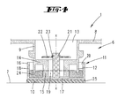
Fig. 3 entsprechende Darstellung, bei einer vertikalen Belastung des Standfußes; - Fig. 5
- eine weitere, der
Fig. 3 entsprechende Darstellung bei einer horizontalen Belastung; - Fig. 6
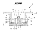
- eine der
Fig. 3 entsprechende Darstellung, bei einer überlagerten vertikalen und horizontalen Belastung. - Dargestellt und beschrieben ist zunächst mit Bezug zu
Fig. 1 eine Küchenmaschine 1 mit einer Rührgefäß-Aufnahme 2 und einem Bedienfeld 3. - Der Küchenmaschine 1 ist ein Rührtopf 4 zugeordnet. Dieser sitzt in der Rührgefäß-Aufnahme 2 ein. In dem Rührtopf 4 ist zugeordnet einem Rührtopfboden ein Rührwerk vorgesehen, welches über einen in der Küchenmaschine 1 unterhalb der Aufnahme 2 angeordneten, nicht dargestellten Elektroantrieb betrieben wird.
- Das Gehäuse 5 der Küchenmaschine 1 stützt sich über Stützfüße 6 auf einer Fläche, hier einer Tischfläche 7 ab. Die Stützfüße 6 sind hierzu unterseitig eines Gehäusebodens 8 befestigt.
- Die Küchenmaschine 1 ist unter anderem geeignet zur Herstellung von Teigen. In einem solchen Teigmodus wird mit dem sich drehenden Rührwerk durch die Zähigkeit des Teiges ein hoher Widerstand entgegengesetzt. Das erforderliche Antriebsmoment des Motors wird, natürlich bei sonstigem Motorbetrieb auch, über das Gehäuse 5 und die Stützfüße 6 abgestützt. Ist die Teigkugel ungünstig im Rührgefäß 4 angeordnet, bleibt das Rührwerk gegebenenfalls kurzzeitig im Teig stecken. Zufolge dessen wird das Drehmoment kurzzeitig erhöht. Auch ein solcher Momentenstoß wird von den Stützfüßen 6 kompensiert, so dass sich das Gerät nicht ruckartig und sprunghaft um seinen Schwerpunkt dreht. Darüber hinaus werden über die Stützfüße 6 Vibrationen bzw. insbesondere vertikale Stöße in Richtung auf die Tischfläche 7 kompensiert.
- Die Bewegung des Gehäuses 5 in horizontaler Richtung (vergleiche Pfeil a und b in
Fig. 1 ) wird zugelassen. Das Gehäuse 5 kann sich relativ zu den Stützfüßen 6 bzw., wie nachstehend näher erläutert, relativ zu einem Teilabschnitt der Stützfüße 6 in der horizontalen Ebene bewegen. Die gegebenenfalls sprungartig eingeleitete Energie wird in Reibung und/oder Rückstell- und Verformungsenergie umgewandelt. Die Stützfüße 6 sind hierbei bevorzugt auf der Standfläche - hier der Tischfläche 7 - nur aufsitzend und durch Reibschluss an einer Bewegung relativ zu der Standfläche gehindert. Darüber hinaus sind durch die Ausgestaltung der Stützfüße 6 zudem auch relative Vertikalbewegungen des sich über die Stützfüße 6 abstützenden Gehäuses 5 insbesondere relativ zu einem Teilabschnitt der Stützfüße 6 gegeben. - Jeder Stützfuß 6 ist im Wesentlichen zweiteilig gestaltet, wobei ein Teil gehäusefest vorgesehen ist. Hierbei handelt es sich um einen Fortsatz 9, der gehäuseseitig, insbesondere gehäusebodenseitig, angeformt ist und nach vertikal unten über die nach unten gerichtete Gehäusebodenfläche frei abragt. In alternativer Ausgestaltung ist der Fortsatz 9 bevorzugt oberhalb des Gehäusebodens 8 mit einem Wiegebalken einer Wägevorrichtung bevorzugt starr verbunden, welcher Wiegebalken anderenends wiederum an dem Gehäuse, insbesondere Gehäuseboden 8 angreift.
- Der Fortsatz 9 ist als Starrteil ausgebildet, weiter bevorzugt zufolge einstückiger, materialeinheitlicher Ausgestaltung zusammen mit dem Gehäuseboden 8. Entsprechend kann es sich bei dem Fortsatz 9 um einen Hartkunststoff- oder Metallkörper handeln, der weiter bevorzugt mit Bezug auf eine zentral den Fortsatz 9 durchsetzende Vertikalachse x rotationssymmetrisch ausgebildet ist. Neben der einstückigen Ausgestaltung ist weiter alternativ ein Fortsatz 9 vorgesehen, der unterseitig am Gehäuseboden 8 festlegbar, beispielsweise einschraubbar ist.
- Der gehäuseseitige Fortsatz 9 sitzt im Wesentlichen auf einem, eine Standfläche 10 ausbildenden Standteil 11 auf, welches Standteil 11 entsprechend im Wesentlichen das zweite Teil des Stützfußes 6 bildet.
- Der Fortsatz 9 ist im Wesentlichen als rotationssymmetrischer Hohlkörper gebildet, mit einer umlaufenden Fortsatzwandung 12. In die durch die Fortsatzwandung 12 umfasste Röhrenöffnung 13 ist mit vertikalem Abstand zur nach vertikal unten freien Randkante der Fortsatzwandung 12 ein Boden 14 einstückig und bevorzugt materialeinheitlich mit der Fortsatzwandung 12 eingezogen.
- An dem Boden 14 ist unterseitig, entsprechend nach vertikal unten gerichtet, eine konzentrisch zur Vertikalachse x angeordneter Röhrenabschnitt 15 angeformt, dessen nach vertikal unten weisende Stirnfläche über die durch die nach unten weisende freie Randkante der Fortsatzwandung 12 definierte Horizontalebene hinausragt. Der vertikale Abstand c zwischen der sich in einer Horizontalebene erstreckenden Stirnfläche des Röhrenabschnittes 15 und der Stirnrandkante der Fortsatzwandung 12 entspricht bevorzugt einem Fünftel bis einem Zehntel, weiter bevorzugt etwa einem Achtel des Außendurchmessers d der Fortsatzwandung 12.
- Das freie radiale Abstandsmaß e zwischen der Wandungsaußenseite des Röhrenabschnittes 15 und der Wandungsinnenseite der Fortsatzwandung 12 entspricht weiter bevorzugt etwa einem Drittel bis einem Halben, weiter bevorzugt etwa einem Viertel des Fortsatzwandungs-Außendurchmessers d.
- Der Röhrenabschnitt 15 ist zentral durchsetzt von einem kreiszylinderförmigen Durchbruch 19, welcher zugleich auch den Boden 14 durchsetzt.
- Das Standteil 11 formt einen nach vertikal oben offenen Schalenabschnitt 16 aus, weist entsprechend einen weiter bevorzugt kreisscheibenförmigen Schalenboden 17 und eine umlaufende Schalenwandung 18 auf. Die vertikale Höhe der Schalenwandung 18 entspricht im Wesentlichen dem vertikalen Erstreckungsmaß des Durchbruchs 19 im Fortsatz 9.
- Der Innendurchmesser f des Schalenabschnittes 16 entspricht bevorzugt dem 1,1- bis 1,5-, weiter bevorzugt dem 1,2- bis 1,4-Fachen des Außendurchmessers d der Fortsatzwandung 12, womit sich in einer wie in
Fig. 3 dargestellten Grundausrichtung umlaufend zwischen der Fortsatzwandung 12 und der Schalenwandung 18 ein Ringspalt 20 einstellt. - Ausgehend von der schaleninnenseitigen Oberfläche des Schalenbodens 17 wächst ein bevorzugt im Querschnitt kreisscheibenförmiger Zapfen 21 aus. Dieser ist bevorzugt zentral angeordnet und einstückig, materialeinheitlich mit dem Schalenabschnitt 16 ausgeformt. Der Durchmesser g ist hierbei kleiner gewählt als der Innendurchmesser h des fortsatzseitigen Durchbruches 19, wobei der Zapfen 21 den Durchbruch 19 durchtretend mit seiner nach vertikal oben weisenden Stirnfläche über die nach oben weisende Ebene des Fortsatz-Bodens 14 hinausragt. Bei konzentrischer Anordnung von Fortsatz 9 und Schalenabschnitt 16 bzw. Standteil 11 ergibt sich zwischen dem Zapfen 21 und der Wandung des Durchbruches 19 ein umlaufender Spalt, dessen Radialmaß bevorzugt gleich oder größer ist dem Radialmaß des Ringspaltes 20.
- Das Standteil 11 ist an dem Fortsatz 9 formschlüssig gehaltert. Hierzu ist eine Übergreifscheibe 22 vorgesehen, welche zentral durchsetzt ist von dem Zapfen 21 und bevorzug auf der nach oben weisenden Oberfläche des Fortsatz-Bodens 14 aufliegt. Ein oberhalb der Übergreifscheibe 22 wandungsaußenseitig an dem Zapfen 21 vorgesehener Kragen 23, bevorzugt in Form eines Sprengringes oder dergleichen fesselt das Standteil 11 über die Übergreifscheibe 22 an dem Fortsatz 9, dies unter Ermöglichung einer vertikalen Beweglichkeit des Standteiles 11 relativ zu dem Fortsatz 9, ausgehend von der Darstellung in
Fig. 3 nach vertikal oben. - Bodenseitig des Standteiles 11 ist ein Weichteil 24 vorgesehen. Dieses ist bevorzugt kreisringförmig gestaltet und besteht weiter bevorzugt aus einem Weichschaumstoff. Das Weichteil 24 sitzt in dem Schalenabschnitt 16 auf dem Schalenboden 17 auf und weist bevorzugt einen an den Innendurchmesser der Schalenwandung 18 angepassten Außendurchmesser auf. Der freie Innendurchmesser des Weichteiles 24 ist weiter bevorzugt angepasst an den Außendurchmesser des fortsatzseitigen Röhrenabschnittes 15, wobei weiter bevorzugt der Kreisring-Innendurchmesser des Weichteiles 24 etwa dem 1,01- bis 1,1-Fachen des Röhrenabschnitt-Außendurchmessers entspricht.
- Das Weichteil 24 ist in einer bevorzugten Ausgestaltung lediglich durch Reib-oder Formschluss in dem Schalenabschnitt 16 gehalten. In alternativer Ausgestaltung ist auch eine Befestigung diesbezüglich möglich, beispielsweise zufolge Verklebung.
- Die vertikale Höhe des Weichteiles 24 entspricht weiter bevorzugt etwa der halben Höhe der Schalenwandung 18, wobei weiter auch vertikale Höhen des Weichteiles 24 von bevorzugt ein Fünftel bis zwei Drittel der Schalenwandungshöhe möglich sind.
- Die Anordnung ist weiter bevorzugt so gewählt, dass in einer unbelasteten Grundstellung gemäß der Darstellung in
Fig. 3 der Fortsatz 9 mit der nach unten weisenden freien Stirnrandkante der Fortsatzwandung 12 auf der nach oben weisenden ringförmigen Oberfläche des Weichteils 24 aufsitzt, während der Röhrenabschnitt 15 des Fortsatzes 9 in die Ringöffnung des Weichteils 24 eintaucht, dies unter vertikaler Beabstandung der nach unten weisenden Röhrenabschnitt-Stirnfläche zur zugewandten Oberfläche des Schalenbodens 17. Diese Stellung ist weiter bevorzugt zudem die Telekop-Auszugsstellung von Fortsatz 9 und Standteil 11, in welcher Stellung sich der Zapfen 21 mit seinem Kragen 23 oberseitig auf der Übergreifscheibe 22 abstützt, welch letztere wiederum bevorzugt auf der zugewandten Oberfläche des fortsatzseitigen Bodens 14 aufliegt. Das Weichteil 24 ist hinsichtlich der Härte bevorzugt so eingestellt, dass dieses in einer Grundbelastung (unter Berücksichtigung eines maximalen Gesamtgewichts der Küchenmaschine 1 und bei nicht aktiviertem Rührwerk) bevorzugt nicht oder nur unwesentlich über die Fortsatzwandung 12 komprimiert wird. - Bei einer wie in
Fig. 4 beispielhaft dargestellten rein vertikal gerichteten Stoßbelastung wird zufolge entsprechenden Eintauchens der Fortsatzwandung 12 in das Weichteil 24 und damit einhergehendem Verdrängen des Weichteilmaterials die gewünschte Dämpfung der Stoßenergie erreicht, wobei bevorzugt zufolge außenseitig umlaufender sowie im Bereich der Kreisringöffnung innenseitiger Abstützung des Weichteils 24 die ringförmige Gestalt des Weichteiles 24 im Wesentlichen stabilisiert ist. - Wie auch die zuvor beschriebene reine vertikale Stoßbelastung ist auch die in
Fig. 5 dargestellte reine horizontale Belastung zufolge Schwingungen eher theoretisch. Eine solche reine horizontale Belastung, entsprechend Schwingungen in der durch die Pfeile a und b inFig. 1 gekennzeichneten Ebene, führen zu einer entsprechenden Verlagerung des Fortsatzes 9 relativ zu dem Standteil 11, wobei der Fortsatz 9 die gemeinsame Vertikalachse x verlässt. Hierbei erfolgt eine Abstützung des fortsatzseitigen Röhrenabschnittes 15 an der zugeordneten Vertikalfäche der Weichteil-Kreisringöffnung, dies weiter unter entsprechender zumindest teilweiser Komprimierung des Weichteilmaterials in der beaufschlagten Zone. Auch hierdurch ist eine ausreichende Dämpfung der Stoßenergie erreicht. - Eine beim üblichen Betrieb einer Küchenmaschine 1 in der Regel auftretende Stoßbelastung sowohl in vertikaler als auch in horizontaler Richtung ist in
Fig. 6 dargestellt. Entsprechend ist das Weichteil 24 sowohl von vertikal oben durch die Fortsatzwandung 12 als auch von radial innen nach radial außen im Bereich der Weichteil-Kreisringöffnung durch den Röhrenabschnitt 15 beaufschlagt. - Der Fortsatz 9 ist insgesamt in allen stoßrelevanten Richtungen durch das Weichteil 24 gedämpft gelagert, wobei das Weichteil 24 bevorzugt so ausgelegt ist, dass dieses über die elastischen Rückstellfähigkeiten den Fortsatz 9 jeweils tendenziell in die Ausgangsposition gemäß
Fig. 3 drängt. Weiter ist die Härte des Weichteiles 24 so gewählt, dass bei üblichen vertikalen Stoßbelastungen insbesondere bei ordnungsgemäßem Betrieb der Küchenmaschine, d.h. weiter bei ordnungsgemäßer Maximalbefüllung des Rührtopfes 4, die nach vertikal unten weisende freie Stirnfläche des Röhrenabschnittes 15 auch in der Maximalbelastung einen vertikalen Abstand zu der zugewandten Oberfläche des Schalenbodens 17 einhält. - Wie weiter dargestellt, ist bevorzugt der Schalenboden 17 unterseitig mit einem Elastomerteil 25 bevorzugt in Form einer gummierten Unterlage versehen. Das Elastomerteil 25 ist unterseitig an dem Standteil 11 befestigt, beispielsweise klebebefestigt, weiter alternativ zusammen mit dem Standteil 11 beispielsweise in einem Zwei-Komponenten-Spritzverfahren hergestellt.
- Die nach unten weisende Fläche des Elastomerteils 25 bildet entsprechend die Standfläche 10 zur Zusammenwirkung mit beispielsweise der Tischfläche 7. Zufolge dieser Ausgestaltung ist das Standteil 11 auch bei über den Fortsatz 9 eingeleiteten Stößen beziehungsweise Vibrationen auf der Tischfläche 7 reibschlussgehaltert.
- Alle offenbarten Merkmale sind (für sich) erfindungswesentlich. In die Offenbarung der Anmeldung wird hiermit auch der Offenbarungsinhalt der zugehörigen/beigefügten Prioritätsunterlagen (Abschrift der Voranmeldung) vollinhaltlich mit einbezogen, auch zu dem Zweck, Merkmale dieser Unterlagen in Ansprüche vorliegender Anmeldung mit aufzunehmen. Die Unteransprüche charakterisieren in ihrer fakultativ nebengeordneten Fassung eigenständige erfinderische Weiterbildungen des Standes der Technik, insbesondere um auf Basis dieser Ansprüche Teilanmeldungen vorzunehmen.
Bezugszeichenliste: 1 Küchenmaschine 2 Rührgefäß-Aufnahme 3 Bedienfeld 4 Rührtopf 5 Gehäuse 6 Stützfuß 7 Tischfläche 8 Gehäuseboden 9 Fortsatz 10 Standfläche 11 Standteil 12 Fortsatzwandung 13 Röhrenöffnung 14 Boden 15 Röhrenabschnitt 16 Schalenabschnitt 17 Schalenboden 18 Schalenwandung 19 Durchbruch 20 Ringspalt 21 Zapfen 22 Übergreifscheibe 23 Kragen 24 Weichteil 25 Elastomerteil a Bewegungsrichtung b Bewegungsrichtung c Abstand d Durchmesser e Abstand f Innendurchmesser g Durchmesser h Durchmesser x Vertikalachse
Claims (10)
- Standfuß (6) eines Gerätes, insbesondere einer Tisch-Küchenmaschine (1), wobei das Gerät ein Gehäuse (5) mit einem bei üblicher Aufstellung nach unten abragenden Fortsatz (9) aufweist, der auf einem eine Standfläche (10) ausbildenden Standteil (11) mittels eines Weichteils (24) aufsitzt, wobei das Weichteil (24) in einem oben offenen Schalenabschnitt (16) des Standteils (11) aufgenommen ist, dadurch gekennzeichnet, dass sich der Fortsatz (9) bis in seitliche Überdeckung zu dem Schalenabschnitt (16) erstreckt.
- Standfuß (6) nach den Merkmalen des Oberbegriffes des Anspruchs 1 oder nach Anspruch 1 oder insbesondere danach, dadurch gekennzeichnet, dass Standteil einen Halterungsfortsatz (9) aufweist, der mit dem Fortsatz (9) zur Halterung des Standteils (11) an dem Fortsatz (9) verbunden ist.
- Standfuß nach einem oder mehreren der vorhergehenden Ansprüche oder insbesondere danach, dadurch gekennzeichnet, dass der Fortsatz (9) mit dem Weichteil (24) zum Einen durch Aufsitzen und zum Anderen durch Zusammenwirkung mit einer freien Seitenfläche, bei relativer Beweglichkeit des Fortsatzes (9) zu der Seitenfläche, zusammenwirkt.
- Standfuß nach einem oder mehreren der vorhergehenden Ansprüche oder insbesondere danach, dadurch gekennzeichnet, dass das Standteil (11) mit dem Fortsatz (9) zur verliersicheren Halterung formschlüssig mit dem Fortsatz (9) zusammenwirkt.
- Standfuß nach einem oder mehreren der vorhergehenden Ansprüche oder insbesondere danach, dadurch gekennzeichnet, dass der Fortsatz (9) in dem Schalenabschnitt (16) unter vertikaler Überdeckung zu dem Schalenabschnitt (16) horizontal und vertikal beweglich aufgenommen ist.
- Standfuß nach einem oder mehreren der vorhergehenden Ansprüche oder insbesondere danach, dadurch gekennzeichnet, dass das Weichteil (24) zumindest teilweise kreisringförmig gestaltet ist.
- Standfuß nach einem oder mehreren der vorhergehenden Ansprüche oder insbesondere danach, dadurch gekennzeichnet, dass der Formschluss durch eine Übergreifscheibe (22) erreicht ist.
- Standfuß nach einem oder mehreren der vorhergehenden Ansprüche oder insbesondere danach, dadurch gekennzeichnet, dass der Fortsatz (9) in seinem in Überdeckung zu dem Standteil (11) befindlichen Abschnitt zumindest teilweise röhrenartig ausgebildet ist.
- Standfuß nach einem oder mehreren der vorhergehenden Ansprüche oder insbesondere danach, dadurch gekennzeichnet, dass das Material des Weichteils (24) und die Überdeckung des Fortsatzes (9) zu dem Weichteil (24) bezüglich aller auf einer Unterlage aufstehender Standfüße eines Gerätes so gewählt bzw. eingestellt ist, dass sich bei 1 mm horizontaler Verschiebung eine Rückstellkraft von 5 N oder mehr einstellt.
- Standfuß nach einem oder mehreren der vorhergehenden Ansprüche oder insbesondere danach, dadurch gekennzeichnet, dass mit zunehmender Horizontalverschiebung die Rückstellkraft überproportional zunimmt.
Priority Applications (1)
| Application Number | Priority Date | Filing Date | Title |
|---|---|---|---|
| PL13166030T PL2659810T3 (pl) | 2012-05-02 | 2013-04-30 | Nóżka urządzenia, zwłaszcza stołowego robota kuchennego |
Applications Claiming Priority (2)
| Application Number | Priority Date | Filing Date | Title |
|---|---|---|---|
| DE102012103810 | 2012-05-02 | ||
| DE102013101907A DE102013101907A1 (de) | 2012-05-02 | 2013-02-26 | Standfuß eines Gerätes, insbesondere einer Tisch-Küchenmaschine |
Publications (2)
| Publication Number | Publication Date |
|---|---|
| EP2659810A1 true EP2659810A1 (de) | 2013-11-06 |
| EP2659810B1 EP2659810B1 (de) | 2018-07-18 |
Family
ID=48190361
Family Applications (1)
| Application Number | Title | Priority Date | Filing Date |
|---|---|---|---|
| EP13166030.0A Active EP2659810B1 (de) | 2012-05-02 | 2013-04-30 | Standfuß eines Gerätes, insbesondere einer Tisch-Küchenmaschine |
Country Status (6)
| Country | Link |
|---|---|
| EP (1) | EP2659810B1 (de) |
| CN (1) | CN103381073B (de) |
| DE (1) | DE102013101907A1 (de) |
| ES (1) | ES2681048T3 (de) |
| PL (1) | PL2659810T3 (de) |
| PT (1) | PT2659810T (de) |
Cited By (3)
| Publication number | Priority date | Publication date | Assignee | Title |
|---|---|---|---|---|
| DE102014116210A1 (de) | 2013-11-06 | 2015-05-07 | Vorwerk & Co. Interholding Gmbh | Standfuß eines Gerätes, insbesondere einer Tisch-Küchenmaschine |
| EP3017738A1 (de) | 2014-11-06 | 2016-05-11 | Vorwerk & Co. Interholding GmbH | Standfuss eines gerätes, insbesondere einer tisch-küchenmaschine |
| US9827843B2 (en) | 2013-06-19 | 2017-11-28 | Tente Gmbh & Co. Kg | Roller having a driven wheel, load truck comprising a roller having a driven wheel and operating device |
Citations (5)
| Publication number | Priority date | Publication date | Assignee | Title |
|---|---|---|---|---|
| US5042765A (en) * | 1990-07-02 | 1991-08-27 | Widerstrom Fahey W | Self adjusting shim device |
| WO2006042432A1 (de) * | 2004-10-21 | 2006-04-27 | Alemis Maschinenbau Gmbh | Abstützvorrichtung für gegenstände wie möbel |
| US20070262213A1 (en) * | 2006-05-11 | 2007-11-15 | Whirlpool S.A. | Self-leveling foot for an appliance |
| JP2008086609A (ja) * | 2006-10-03 | 2008-04-17 | Ishiguro Seisakusho:Kk | 設置面段差吸収型の家具装着脚 |
| WO2008130177A1 (en) * | 2007-04-24 | 2008-10-30 | Lg Electronics Inc. | Damping leg and refrigerator having the same |
Family Cites Families (4)
| Publication number | Priority date | Publication date | Assignee | Title |
|---|---|---|---|---|
| DE29622725U1 (de) | 1996-01-23 | 1997-06-05 | Lic Langmatz Gmbh, 82467 Garmisch-Partenkirchen | Schwingungsdämpfer, insbesondere für Transformatoren |
| JP3062945B2 (ja) * | 1998-02-09 | 2000-07-12 | 株式会社ブリヂストン | 床支持脚用スタンド |
| CN2694050Y (zh) * | 2004-04-21 | 2005-04-20 | 夏齐霄 | 一种带有中心弹性支撑体的缓冲抗震装置 |
| DE102009054201A1 (de) * | 2009-11-21 | 2011-05-26 | Vorwerk & Co. Interholding Gmbh | Standfuß, insbesondere für eine Tisch-Küchenmaschine |
-
2013
- 2013-02-26 DE DE102013101907A patent/DE102013101907A1/de not_active Withdrawn
- 2013-04-30 EP EP13166030.0A patent/EP2659810B1/de active Active
- 2013-04-30 PT PT13166030T patent/PT2659810T/pt unknown
- 2013-04-30 PL PL13166030T patent/PL2659810T3/pl unknown
- 2013-04-30 ES ES13166030.0T patent/ES2681048T3/es active Active
- 2013-05-02 CN CN201310277642.1A patent/CN103381073B/zh active Active
Patent Citations (5)
| Publication number | Priority date | Publication date | Assignee | Title |
|---|---|---|---|---|
| US5042765A (en) * | 1990-07-02 | 1991-08-27 | Widerstrom Fahey W | Self adjusting shim device |
| WO2006042432A1 (de) * | 2004-10-21 | 2006-04-27 | Alemis Maschinenbau Gmbh | Abstützvorrichtung für gegenstände wie möbel |
| US20070262213A1 (en) * | 2006-05-11 | 2007-11-15 | Whirlpool S.A. | Self-leveling foot for an appliance |
| JP2008086609A (ja) * | 2006-10-03 | 2008-04-17 | Ishiguro Seisakusho:Kk | 設置面段差吸収型の家具装着脚 |
| WO2008130177A1 (en) * | 2007-04-24 | 2008-10-30 | Lg Electronics Inc. | Damping leg and refrigerator having the same |
Cited By (4)
| Publication number | Priority date | Publication date | Assignee | Title |
|---|---|---|---|---|
| US9827843B2 (en) | 2013-06-19 | 2017-11-28 | Tente Gmbh & Co. Kg | Roller having a driven wheel, load truck comprising a roller having a driven wheel and operating device |
| DE102014116210A1 (de) | 2013-11-06 | 2015-05-07 | Vorwerk & Co. Interholding Gmbh | Standfuß eines Gerätes, insbesondere einer Tisch-Küchenmaschine |
| EP3017738A1 (de) | 2014-11-06 | 2016-05-11 | Vorwerk & Co. Interholding GmbH | Standfuss eines gerätes, insbesondere einer tisch-küchenmaschine |
| US9976690B2 (en) | 2014-11-06 | 2018-05-22 | Vorwerk & Co. Interholding Gmbh | Foot of a device, in particular of a table-top kitchen appliance |
Also Published As
| Publication number | Publication date |
|---|---|
| PT2659810T (pt) | 2018-11-07 |
| ES2681048T3 (es) | 2018-09-11 |
| DE102013101907A1 (de) | 2013-11-07 |
| PL2659810T3 (pl) | 2018-11-30 |
| CN103381073B (zh) | 2018-12-11 |
| EP2659810B1 (de) | 2018-07-18 |
| CN103381073A (zh) | 2013-11-06 |
Similar Documents
| Publication | Publication Date | Title |
|---|---|---|
| EP3017738B1 (de) | Standfuss eines gerätes, insbesondere einer tisch-küchenmaschine | |
| EP1845822B1 (de) | Tragelement für sitzm\bel | |
| EP1197168A2 (de) | Lagerung für einen Sitz | |
| DE1282262B (de) | Stuhl | |
| DE4006608A1 (de) | Sitzmoebel mit einer schwingenden sitzflaeche | |
| DE20019569U1 (de) | Sitzvorrichtung für ein Sitzmöbel | |
| WO2013131658A1 (de) | Funktionsstuhl | |
| EP2659810B1 (de) | Standfuß eines Gerätes, insbesondere einer Tisch-Küchenmaschine | |
| DE102010016989B4 (de) | Kippvorrichtung zum Neigen einer Fläche, insbesondere einer Sitzfläche und Stuhl mit einer solchen Kippvorrichtung | |
| EP2325520B1 (de) | Standfuß, insbesondere für eine Tisch-Küchenmaschine | |
| DE202021004413U1 (de) | Einsatzmodul für einen Topf eines Küchengeräts | |
| EP2870903B1 (de) | Standfuß einer Tisch-Küchenmaschine | |
| DE3829440A1 (de) | Sitz- oder ruhemoebel | |
| EP1493357B1 (de) | Haushaltsmaschine und Standfuss für eine Haushaltsmaschine, insbesondere Waschmaschine oder Wäscheschleuder | |
| DE112020002777T5 (de) | Kippbarer Hocker | |
| WO2009024329A1 (de) | Pendel-hocker | |
| DE102008008919B4 (de) | Dentalgerät | |
| DE202011000995U1 (de) | Standfuß, insbesondere für eine Tisch-Küchenmaschine | |
| DE202008017086U1 (de) | Bewegungsstuhl | |
| WO2022228736A1 (de) | Aktivdynamisches sitzmöbel | |
| DE202016000382U1 (de) | 3D bewegliche Sitzvorrichtung | |
| DE202011004345U1 (de) | Stehhilfe | |
| DE202018100096U1 (de) | Sitzlagerung und Stuhl | |
| CH179295A (de) | Anordnung für die nachgiebige Lagerung eines getragenen Teils auf einem tragenden Teil. |
Legal Events
| Date | Code | Title | Description |
|---|---|---|---|
| PUAI | Public reference made under article 153(3) epc to a published international application that has entered the european phase |
Free format text: ORIGINAL CODE: 0009012 |
|
| AK | Designated contracting states |
Kind code of ref document: A1 Designated state(s): AL AT BE BG CH CY CZ DE DK EE ES FI FR GB GR HR HU IE IS IT LI LT LU LV MC MK MT NL NO PL PT RO RS SE SI SK SM TR |
|
| AX | Request for extension of the european patent |
Extension state: BA ME |
|
| 17P | Request for examination filed |
Effective date: 20131212 |
|
| RBV | Designated contracting states (corrected) |
Designated state(s): AL AT BE BG CH CY CZ DE DK EE ES FI FR GB GR HR HU IE IS IT LI LT LU LV MC MK MT NL NO PL PT RO RS SE SI SK SM TR |
|
| 17Q | First examination report despatched |
Effective date: 20150407 |
|
| GRAP | Despatch of communication of intention to grant a patent |
Free format text: ORIGINAL CODE: EPIDOSNIGR1 |
|
| STAA | Information on the status of an ep patent application or granted ep patent |
Free format text: STATUS: GRANT OF PATENT IS INTENDED |
|
| INTG | Intention to grant announced |
Effective date: 20180102 |
|
| GRAS | Grant fee paid |
Free format text: ORIGINAL CODE: EPIDOSNIGR3 |
|
| GRAJ | Information related to disapproval of communication of intention to grant by the applicant or resumption of examination proceedings by the epo deleted |
Free format text: ORIGINAL CODE: EPIDOSDIGR1 |
|
| GRAL | Information related to payment of fee for publishing/printing deleted |
Free format text: ORIGINAL CODE: EPIDOSDIGR3 |
|
| STAA | Information on the status of an ep patent application or granted ep patent |
Free format text: STATUS: EXAMINATION IS IN PROGRESS |
|
| GRAR | Information related to intention to grant a patent recorded |
Free format text: ORIGINAL CODE: EPIDOSNIGR71 |
|
| INTC | Intention to grant announced (deleted) | ||
| STAA | Information on the status of an ep patent application or granted ep patent |
Free format text: STATUS: GRANT OF PATENT IS INTENDED |
|
| GRAA | (expected) grant |
Free format text: ORIGINAL CODE: 0009210 |
|
| STAA | Information on the status of an ep patent application or granted ep patent |
Free format text: STATUS: THE PATENT HAS BEEN GRANTED |
|
| INTG | Intention to grant announced |
Effective date: 20180606 |
|
| AK | Designated contracting states |
Kind code of ref document: B1 Designated state(s): AL AT BE BG CH CY CZ DE DK EE ES FI FR GB GR HR HU IE IS IT LI LT LU LV MC MK MT NL NO PL PT RO RS SE SI SK SM TR |
|
| REG | Reference to a national code |
Ref country code: GB Ref legal event code: FG4D Free format text: NOT ENGLISH |
|
| REG | Reference to a national code |
Ref country code: CH Ref legal event code: EP |
|
| REG | Reference to a national code |
Ref country code: IE Ref legal event code: FG4D Free format text: LANGUAGE OF EP DOCUMENT: GERMAN |
|
| REG | Reference to a national code |
Ref country code: AT Ref legal event code: REF Ref document number: 1018458 Country of ref document: AT Kind code of ref document: T Effective date: 20180815 |
|
| REG | Reference to a national code |
Ref country code: DE Ref legal event code: R096 Ref document number: 502013010623 Country of ref document: DE |
|
| REG | Reference to a national code |
Ref country code: ES Ref legal event code: FG2A Ref document number: 2681048 Country of ref document: ES Kind code of ref document: T3 Effective date: 20180911 |
|
| REG | Reference to a national code |
Ref country code: PT Ref legal event code: SC4A Ref document number: 2659810 Country of ref document: PT Date of ref document: 20181107 Kind code of ref document: T Free format text: AVAILABILITY OF NATIONAL TRANSLATION Effective date: 20181010 |
|
| REG | Reference to a national code |
Ref country code: NL Ref legal event code: MP Effective date: 20180718 |
|
| REG | Reference to a national code |
Ref country code: LT Ref legal event code: MG4D |
|
| PG25 | Lapsed in a contracting state [announced via postgrant information from national office to epo] |
Ref country code: NL Free format text: LAPSE BECAUSE OF FAILURE TO SUBMIT A TRANSLATION OF THE DESCRIPTION OR TO PAY THE FEE WITHIN THE PRESCRIBED TIME-LIMIT Effective date: 20180718 |
|
| PG25 | Lapsed in a contracting state [announced via postgrant information from national office to epo] |
Ref country code: RS Free format text: LAPSE BECAUSE OF FAILURE TO SUBMIT A TRANSLATION OF THE DESCRIPTION OR TO PAY THE FEE WITHIN THE PRESCRIBED TIME-LIMIT Effective date: 20180718 Ref country code: IS Free format text: LAPSE BECAUSE OF FAILURE TO SUBMIT A TRANSLATION OF THE DESCRIPTION OR TO PAY THE FEE WITHIN THE PRESCRIBED TIME-LIMIT Effective date: 20181118 Ref country code: LT Free format text: LAPSE BECAUSE OF FAILURE TO SUBMIT A TRANSLATION OF THE DESCRIPTION OR TO PAY THE FEE WITHIN THE PRESCRIBED TIME-LIMIT Effective date: 20180718 Ref country code: SE Free format text: LAPSE BECAUSE OF FAILURE TO SUBMIT A TRANSLATION OF THE DESCRIPTION OR TO PAY THE FEE WITHIN THE PRESCRIBED TIME-LIMIT Effective date: 20180718 Ref country code: BG Free format text: LAPSE BECAUSE OF FAILURE TO SUBMIT A TRANSLATION OF THE DESCRIPTION OR TO PAY THE FEE WITHIN THE PRESCRIBED TIME-LIMIT Effective date: 20181018 Ref country code: FI Free format text: LAPSE BECAUSE OF FAILURE TO SUBMIT A TRANSLATION OF THE DESCRIPTION OR TO PAY THE FEE WITHIN THE PRESCRIBED TIME-LIMIT Effective date: 20180718 Ref country code: GR Free format text: LAPSE BECAUSE OF FAILURE TO SUBMIT A TRANSLATION OF THE DESCRIPTION OR TO PAY THE FEE WITHIN THE PRESCRIBED TIME-LIMIT Effective date: 20181019 Ref country code: NO Free format text: LAPSE BECAUSE OF FAILURE TO SUBMIT A TRANSLATION OF THE DESCRIPTION OR TO PAY THE FEE WITHIN THE PRESCRIBED TIME-LIMIT Effective date: 20181018 |
|
| PG25 | Lapsed in a contracting state [announced via postgrant information from national office to epo] |
Ref country code: LV Free format text: LAPSE BECAUSE OF FAILURE TO SUBMIT A TRANSLATION OF THE DESCRIPTION OR TO PAY THE FEE WITHIN THE PRESCRIBED TIME-LIMIT Effective date: 20180718 Ref country code: HR Free format text: LAPSE BECAUSE OF FAILURE TO SUBMIT A TRANSLATION OF THE DESCRIPTION OR TO PAY THE FEE WITHIN THE PRESCRIBED TIME-LIMIT Effective date: 20180718 Ref country code: AL Free format text: LAPSE BECAUSE OF FAILURE TO SUBMIT A TRANSLATION OF THE DESCRIPTION OR TO PAY THE FEE WITHIN THE PRESCRIBED TIME-LIMIT Effective date: 20180718 |
|
| REG | Reference to a national code |
Ref country code: DE Ref legal event code: R097 Ref document number: 502013010623 Country of ref document: DE |
|
| PG25 | Lapsed in a contracting state [announced via postgrant information from national office to epo] |
Ref country code: EE Free format text: LAPSE BECAUSE OF FAILURE TO SUBMIT A TRANSLATION OF THE DESCRIPTION OR TO PAY THE FEE WITHIN THE PRESCRIBED TIME-LIMIT Effective date: 20180718 Ref country code: RO Free format text: LAPSE BECAUSE OF FAILURE TO SUBMIT A TRANSLATION OF THE DESCRIPTION OR TO PAY THE FEE WITHIN THE PRESCRIBED TIME-LIMIT Effective date: 20180718 Ref country code: CZ Free format text: LAPSE BECAUSE OF FAILURE TO SUBMIT A TRANSLATION OF THE DESCRIPTION OR TO PAY THE FEE WITHIN THE PRESCRIBED TIME-LIMIT Effective date: 20180718 |
|
| PLBE | No opposition filed within time limit |
Free format text: ORIGINAL CODE: 0009261 |
|
| STAA | Information on the status of an ep patent application or granted ep patent |
Free format text: STATUS: NO OPPOSITION FILED WITHIN TIME LIMIT |
|
| PG25 | Lapsed in a contracting state [announced via postgrant information from national office to epo] |
Ref country code: SK Free format text: LAPSE BECAUSE OF FAILURE TO SUBMIT A TRANSLATION OF THE DESCRIPTION OR TO PAY THE FEE WITHIN THE PRESCRIBED TIME-LIMIT Effective date: 20180718 Ref country code: DK Free format text: LAPSE BECAUSE OF FAILURE TO SUBMIT A TRANSLATION OF THE DESCRIPTION OR TO PAY THE FEE WITHIN THE PRESCRIBED TIME-LIMIT Effective date: 20180718 Ref country code: SM Free format text: LAPSE BECAUSE OF FAILURE TO SUBMIT A TRANSLATION OF THE DESCRIPTION OR TO PAY THE FEE WITHIN THE PRESCRIBED TIME-LIMIT Effective date: 20180718 |
|
| 26N | No opposition filed |
Effective date: 20190423 |
|
| PG25 | Lapsed in a contracting state [announced via postgrant information from national office to epo] |
Ref country code: SI Free format text: LAPSE BECAUSE OF FAILURE TO SUBMIT A TRANSLATION OF THE DESCRIPTION OR TO PAY THE FEE WITHIN THE PRESCRIBED TIME-LIMIT Effective date: 20180718 |
|
| REG | Reference to a national code |
Ref country code: CH Ref legal event code: PL |
|
| REG | Reference to a national code |
Ref country code: BE Ref legal event code: MM Effective date: 20190430 |
|
| PG25 | Lapsed in a contracting state [announced via postgrant information from national office to epo] |
Ref country code: MC Free format text: LAPSE BECAUSE OF FAILURE TO SUBMIT A TRANSLATION OF THE DESCRIPTION OR TO PAY THE FEE WITHIN THE PRESCRIBED TIME-LIMIT Effective date: 20180718 Ref country code: LU Free format text: LAPSE BECAUSE OF NON-PAYMENT OF DUE FEES Effective date: 20190430 |
|
| PG25 | Lapsed in a contracting state [announced via postgrant information from national office to epo] |
Ref country code: CH Free format text: LAPSE BECAUSE OF NON-PAYMENT OF DUE FEES Effective date: 20190430 Ref country code: LI Free format text: LAPSE BECAUSE OF NON-PAYMENT OF DUE FEES Effective date: 20190430 |
|
| PG25 | Lapsed in a contracting state [announced via postgrant information from national office to epo] |
Ref country code: BE Free format text: LAPSE BECAUSE OF NON-PAYMENT OF DUE FEES Effective date: 20190430 |
|
| PG25 | Lapsed in a contracting state [announced via postgrant information from national office to epo] |
Ref country code: IE Free format text: LAPSE BECAUSE OF NON-PAYMENT OF DUE FEES Effective date: 20190430 |
|
| REG | Reference to a national code |
Ref country code: AT Ref legal event code: MM01 Ref document number: 1018458 Country of ref document: AT Kind code of ref document: T Effective date: 20190430 |
|
| PG25 | Lapsed in a contracting state [announced via postgrant information from national office to epo] |
Ref country code: AT Free format text: LAPSE BECAUSE OF NON-PAYMENT OF DUE FEES Effective date: 20190430 |
|
| PG25 | Lapsed in a contracting state [announced via postgrant information from national office to epo] |
Ref country code: CY Free format text: LAPSE BECAUSE OF FAILURE TO SUBMIT A TRANSLATION OF THE DESCRIPTION OR TO PAY THE FEE WITHIN THE PRESCRIBED TIME-LIMIT Effective date: 20180718 |
|
| PG25 | Lapsed in a contracting state [announced via postgrant information from national office to epo] |
Ref country code: HU Free format text: LAPSE BECAUSE OF FAILURE TO SUBMIT A TRANSLATION OF THE DESCRIPTION OR TO PAY THE FEE WITHIN THE PRESCRIBED TIME-LIMIT; INVALID AB INITIO Effective date: 20130430 Ref country code: MT Free format text: LAPSE BECAUSE OF FAILURE TO SUBMIT A TRANSLATION OF THE DESCRIPTION OR TO PAY THE FEE WITHIN THE PRESCRIBED TIME-LIMIT Effective date: 20180718 |
|
| PGFP | Annual fee paid to national office [announced via postgrant information from national office to epo] |
Ref country code: TR Payment date: 20210420 Year of fee payment: 9 |
|
| PG25 | Lapsed in a contracting state [announced via postgrant information from national office to epo] |
Ref country code: MK Free format text: LAPSE BECAUSE OF FAILURE TO SUBMIT A TRANSLATION OF THE DESCRIPTION OR TO PAY THE FEE WITHIN THE PRESCRIBED TIME-LIMIT Effective date: 20180718 |
|
| P01 | Opt-out of the competence of the unified patent court (upc) registered |
Effective date: 20230517 |
|
| PGFP | Annual fee paid to national office [announced via postgrant information from national office to epo] |
Ref country code: PL Payment date: 20250417 Year of fee payment: 13 Ref country code: DE Payment date: 20250417 Year of fee payment: 13 |
|
| PGFP | Annual fee paid to national office [announced via postgrant information from national office to epo] |
Ref country code: ES Payment date: 20250519 Year of fee payment: 13 |
|
| PGFP | Annual fee paid to national office [announced via postgrant information from national office to epo] |
Ref country code: IT Payment date: 20250430 Year of fee payment: 13 |
|
| PGFP | Annual fee paid to national office [announced via postgrant information from national office to epo] |
Ref country code: PT Payment date: 20250429 Year of fee payment: 13 |
|
| PGFP | Annual fee paid to national office [announced via postgrant information from national office to epo] |
Ref country code: FR Payment date: 20250422 Year of fee payment: 13 |
|
| PGFP | Annual fee paid to national office [announced via postgrant information from national office to epo] |
Ref country code: GB Payment date: 20260324 Year of fee payment: 14 |