EP2657988A2 - Solar photovoltaic-thermal system - Google Patents
Solar photovoltaic-thermal system Download PDFInfo
- Publication number
- EP2657988A2 EP2657988A2 EP13165493.1A EP13165493A EP2657988A2 EP 2657988 A2 EP2657988 A2 EP 2657988A2 EP 13165493 A EP13165493 A EP 13165493A EP 2657988 A2 EP2657988 A2 EP 2657988A2
- Authority
- EP
- European Patent Office
- Prior art keywords
- transparent
- thermal system
- film
- light
- solar photovoltaic
- Prior art date
- Legal status (The legal status is an assumption and is not a legal conclusion. Google has not performed a legal analysis and makes no representation as to the accuracy of the status listed.)
- Granted
Links
- 239000011521 glass Substances 0.000 claims description 31
- 239000000463 material Substances 0.000 claims description 22
- 229910044991 metal oxide Inorganic materials 0.000 claims description 20
- 150000004706 metal oxides Chemical class 0.000 claims description 20
- JAONJTDQXUSBGG-UHFFFAOYSA-N dialuminum;dizinc;oxygen(2-) Chemical compound [O-2].[O-2].[O-2].[O-2].[O-2].[Al+3].[Al+3].[Zn+2].[Zn+2] JAONJTDQXUSBGG-UHFFFAOYSA-N 0.000 claims description 19
- 229910052751 metal Inorganic materials 0.000 claims description 16
- 239000002184 metal Substances 0.000 claims description 16
- BQCADISMDOOEFD-UHFFFAOYSA-N Silver Chemical compound [Ag] BQCADISMDOOEFD-UHFFFAOYSA-N 0.000 claims description 14
- 229910052709 silver Inorganic materials 0.000 claims description 14
- 239000004332 silver Substances 0.000 claims description 14
- XLOMVQKBTHCTTD-UHFFFAOYSA-N Zinc monoxide Chemical compound [Zn]=O XLOMVQKBTHCTTD-UHFFFAOYSA-N 0.000 claims description 9
- 239000005341 toughened glass Substances 0.000 claims description 9
- 230000003287 optical effect Effects 0.000 claims description 7
- GWEVSGVZZGPLCZ-UHFFFAOYSA-N Titan oxide Chemical compound O=[Ti]=O GWEVSGVZZGPLCZ-UHFFFAOYSA-N 0.000 claims description 5
- 229910052782 aluminium Inorganic materials 0.000 claims description 4
- XAGFODPZIPBFFR-UHFFFAOYSA-N aluminium Chemical compound [Al] XAGFODPZIPBFFR-UHFFFAOYSA-N 0.000 claims description 4
- TZCXTZWJZNENPQ-UHFFFAOYSA-L barium sulfate Chemical compound [Ba+2].[O-]S([O-])(=O)=O TZCXTZWJZNENPQ-UHFFFAOYSA-L 0.000 claims description 4
- 239000007769 metal material Substances 0.000 claims description 4
- 239000011787 zinc oxide Substances 0.000 claims description 4
- VYZAMTAEIAYCRO-UHFFFAOYSA-N Chromium Chemical compound [Cr] VYZAMTAEIAYCRO-UHFFFAOYSA-N 0.000 claims description 3
- GYHNNYVSQQEPJS-UHFFFAOYSA-N Gallium Chemical compound [Ga] GYHNNYVSQQEPJS-UHFFFAOYSA-N 0.000 claims description 3
- 229910052804 chromium Inorganic materials 0.000 claims description 3
- 239000011651 chromium Substances 0.000 claims description 3
- 229910052733 gallium Inorganic materials 0.000 claims description 3
- PCHJSUWPFVWCPO-UHFFFAOYSA-N gold Chemical compound [Au] PCHJSUWPFVWCPO-UHFFFAOYSA-N 0.000 claims description 3
- 229910052737 gold Inorganic materials 0.000 claims description 3
- 239000010931 gold Substances 0.000 claims description 3
- 239000004809 Teflon Substances 0.000 claims description 2
- 229920006362 Teflon® Polymers 0.000 claims description 2
- 238000005452 bending Methods 0.000 claims description 2
- 229910052755 nonmetal Inorganic materials 0.000 claims description 2
- 230000008021 deposition Effects 0.000 claims 1
- 210000004027 cell Anatomy 0.000 description 33
- 239000010408 film Substances 0.000 description 29
- 239000012530 fluid Substances 0.000 description 8
- 238000010438 heat treatment Methods 0.000 description 7
- 238000000034 method Methods 0.000 description 7
- -1 polyethylene Polymers 0.000 description 6
- 239000004698 Polyethylene Substances 0.000 description 4
- 239000004743 Polypropylene Substances 0.000 description 4
- 229920000573 polyethylene Polymers 0.000 description 4
- 229920001155 polypropylene Polymers 0.000 description 4
- 229920005989 resin Polymers 0.000 description 4
- 239000011347 resin Substances 0.000 description 4
- 239000000853 adhesive Substances 0.000 description 3
- 230000001070 adhesive effect Effects 0.000 description 3
- 230000005540 biological transmission Effects 0.000 description 3
- 239000005038 ethylene vinyl acetate Substances 0.000 description 3
- 239000007789 gas Substances 0.000 description 3
- 230000002093 peripheral effect Effects 0.000 description 3
- 229920003023 plastic Polymers 0.000 description 3
- 239000004033 plastic Substances 0.000 description 3
- 229920003229 poly(methyl methacrylate) Polymers 0.000 description 3
- 229920000139 polyethylene terephthalate Polymers 0.000 description 3
- 239000005020 polyethylene terephthalate Substances 0.000 description 3
- 239000004926 polymethyl methacrylate Substances 0.000 description 3
- 238000005496 tempering Methods 0.000 description 3
- XLYOFNOQVPJJNP-UHFFFAOYSA-N water Substances O XLYOFNOQVPJJNP-UHFFFAOYSA-N 0.000 description 3
- DQXBYHZEEUGOBF-UHFFFAOYSA-N but-3-enoic acid;ethene Chemical compound C=C.OC(=O)CC=C DQXBYHZEEUGOBF-UHFFFAOYSA-N 0.000 description 2
- 238000001816 cooling Methods 0.000 description 2
- 230000000694 effects Effects 0.000 description 2
- 239000000203 mixture Substances 0.000 description 2
- 230000035515 penetration Effects 0.000 description 2
- 229920001200 poly(ethylene-vinyl acetate) Polymers 0.000 description 2
- 229920000747 poly(lactic acid) Polymers 0.000 description 2
- 229920003050 poly-cycloolefin Polymers 0.000 description 2
- 239000004626 polylactic acid Substances 0.000 description 2
- 239000002952 polymeric resin Substances 0.000 description 2
- 229920002620 polyvinyl fluoride Polymers 0.000 description 2
- 230000035939 shock Effects 0.000 description 2
- 229920003002 synthetic resin Polymers 0.000 description 2
- 239000004925 Acrylic resin Substances 0.000 description 1
- RYGMFSIKBFXOCR-UHFFFAOYSA-N Copper Chemical compound [Cu] RYGMFSIKBFXOCR-UHFFFAOYSA-N 0.000 description 1
- 229920000181 Ethylene propylene rubber Polymers 0.000 description 1
- 229910001335 Galvanized steel Inorganic materials 0.000 description 1
- 239000011358 absorbing material Substances 0.000 description 1
- 230000009286 beneficial effect Effects 0.000 description 1
- 210000003850 cellular structure Anatomy 0.000 description 1
- 229920002678 cellulose Polymers 0.000 description 1
- 239000001913 cellulose Substances 0.000 description 1
- 238000006243 chemical reaction Methods 0.000 description 1
- 239000004020 conductor Substances 0.000 description 1
- 229910052802 copper Inorganic materials 0.000 description 1
- 239000010949 copper Substances 0.000 description 1
- 229910021419 crystalline silicon Inorganic materials 0.000 description 1
- 230000001419 dependent effect Effects 0.000 description 1
- 230000006866 deterioration Effects 0.000 description 1
- 238000005516 engineering process Methods 0.000 description 1
- 230000007613 environmental effect Effects 0.000 description 1
- 239000005357 flat glass Substances 0.000 description 1
- 239000008397 galvanized steel Substances 0.000 description 1
- 229910052738 indium Inorganic materials 0.000 description 1
- APFVFJFRJDLVQX-UHFFFAOYSA-N indium atom Chemical compound [In] APFVFJFRJDLVQX-UHFFFAOYSA-N 0.000 description 1
- 229910003437 indium oxide Inorganic materials 0.000 description 1
- PJXISJQVUVHSOJ-UHFFFAOYSA-N indium(iii) oxide Chemical compound [O-2].[O-2].[O-2].[In+3].[In+3] PJXISJQVUVHSOJ-UHFFFAOYSA-N 0.000 description 1
- UAFICZUDNYNDQU-UHFFFAOYSA-N indium;oxomolybdenum Chemical compound [In].[Mo]=O UAFICZUDNYNDQU-UHFFFAOYSA-N 0.000 description 1
- AMGQUBHHOARCQH-UHFFFAOYSA-N indium;oxotin Chemical compound [In].[Sn]=O AMGQUBHHOARCQH-UHFFFAOYSA-N 0.000 description 1
- 230000001678 irradiating effect Effects 0.000 description 1
- 238000003754 machining Methods 0.000 description 1
- 238000004519 manufacturing process Methods 0.000 description 1
- 230000007246 mechanism Effects 0.000 description 1
- 150000002739 metals Chemical class 0.000 description 1
- 238000005240 physical vapour deposition Methods 0.000 description 1
- 229920005668 polycarbonate resin Polymers 0.000 description 1
- 239000004431 polycarbonate resin Substances 0.000 description 1
- 229920001225 polyester resin Polymers 0.000 description 1
- 239000004645 polyester resin Substances 0.000 description 1
- 239000011112 polyethylene naphthalate Substances 0.000 description 1
- 229920001721 polyimide Polymers 0.000 description 1
- 239000009719 polyimide resin Substances 0.000 description 1
- 229920005672 polyolefin resin Polymers 0.000 description 1
- 229920005990 polystyrene resin Polymers 0.000 description 1
- 229920005749 polyurethane resin Polymers 0.000 description 1
- 238000002360 preparation method Methods 0.000 description 1
- 230000003252 repetitive effect Effects 0.000 description 1
- 239000010935 stainless steel Substances 0.000 description 1
- 229910001220 stainless steel Inorganic materials 0.000 description 1
- 239000000758 substrate Substances 0.000 description 1
- 229920002994 synthetic fiber Polymers 0.000 description 1
- 229920001187 thermosetting polymer Polymers 0.000 description 1
- 239000010409 thin film Substances 0.000 description 1
- OGIDPMRJRNCKJF-UHFFFAOYSA-N titanium oxide Inorganic materials [Ti]=O OGIDPMRJRNCKJF-UHFFFAOYSA-N 0.000 description 1
- ILJSQTXMGCGYMG-UHFFFAOYSA-N triacetic acid Chemical compound CC(=O)CC(=O)CC(O)=O ILJSQTXMGCGYMG-UHFFFAOYSA-N 0.000 description 1
- 239000002023 wood Substances 0.000 description 1
- YVTHLONGBIQYBO-UHFFFAOYSA-N zinc indium(3+) oxygen(2-) Chemical compound [O--].[Zn++].[In+3] YVTHLONGBIQYBO-UHFFFAOYSA-N 0.000 description 1
Images


Classifications
-
- H—ELECTRICITY
- H01—ELECTRIC ELEMENTS
- H01L—SEMICONDUCTOR DEVICES NOT COVERED BY CLASS H10
- H01L31/00—Semiconductor devices sensitive to infrared radiation, light, electromagnetic radiation of shorter wavelength or corpuscular radiation and specially adapted either for the conversion of the energy of such radiation into electrical energy or for the control of electrical energy by such radiation; Processes or apparatus specially adapted for the manufacture or treatment thereof or of parts thereof; Details thereof
- H01L31/04—Semiconductor devices sensitive to infrared radiation, light, electromagnetic radiation of shorter wavelength or corpuscular radiation and specially adapted either for the conversion of the energy of such radiation into electrical energy or for the control of electrical energy by such radiation; Processes or apparatus specially adapted for the manufacture or treatment thereof or of parts thereof; Details thereof adapted as photovoltaic [PV] conversion devices
- H01L31/054—Optical elements directly associated or integrated with the PV cell, e.g. light-reflecting means or light-concentrating means
- H01L31/0547—Optical elements directly associated or integrated with the PV cell, e.g. light-reflecting means or light-concentrating means comprising light concentrating means of the reflecting type, e.g. parabolic mirrors, concentrators using total internal reflection
-
- H—ELECTRICITY
- H01—ELECTRIC ELEMENTS
- H01L—SEMICONDUCTOR DEVICES NOT COVERED BY CLASS H10
- H01L31/00—Semiconductor devices sensitive to infrared radiation, light, electromagnetic radiation of shorter wavelength or corpuscular radiation and specially adapted either for the conversion of the energy of such radiation into electrical energy or for the control of electrical energy by such radiation; Processes or apparatus specially adapted for the manufacture or treatment thereof or of parts thereof; Details thereof
- H01L31/04—Semiconductor devices sensitive to infrared radiation, light, electromagnetic radiation of shorter wavelength or corpuscular radiation and specially adapted either for the conversion of the energy of such radiation into electrical energy or for the control of electrical energy by such radiation; Processes or apparatus specially adapted for the manufacture or treatment thereof or of parts thereof; Details thereof adapted as photovoltaic [PV] conversion devices
- H01L31/042—PV modules or arrays of single PV cells
- H01L31/048—Encapsulation of modules
- H01L31/0488—Double glass encapsulation, e.g. photovoltaic cells arranged between front and rear glass sheets
-
- H—ELECTRICITY
- H02—GENERATION; CONVERSION OR DISTRIBUTION OF ELECTRIC POWER
- H02S—GENERATION OF ELECTRIC POWER BY CONVERSION OF INFRARED RADIATION, VISIBLE LIGHT OR ULTRAVIOLET LIGHT, e.g. USING PHOTOVOLTAIC [PV] MODULES
- H02S40/00—Components or accessories in combination with PV modules, not provided for in groups H02S10/00 - H02S30/00
- H02S40/40—Thermal components
- H02S40/44—Means to utilise heat energy, e.g. hybrid systems producing warm water and electricity at the same time
-
- Y—GENERAL TAGGING OF NEW TECHNOLOGICAL DEVELOPMENTS; GENERAL TAGGING OF CROSS-SECTIONAL TECHNOLOGIES SPANNING OVER SEVERAL SECTIONS OF THE IPC; TECHNICAL SUBJECTS COVERED BY FORMER USPC CROSS-REFERENCE ART COLLECTIONS [XRACs] AND DIGESTS
- Y02—TECHNOLOGIES OR APPLICATIONS FOR MITIGATION OR ADAPTATION AGAINST CLIMATE CHANGE
- Y02E—REDUCTION OF GREENHOUSE GAS [GHG] EMISSIONS, RELATED TO ENERGY GENERATION, TRANSMISSION OR DISTRIBUTION
- Y02E10/00—Energy generation through renewable energy sources
- Y02E10/50—Photovoltaic [PV] energy
- Y02E10/52—PV systems with concentrators
-
- Y—GENERAL TAGGING OF NEW TECHNOLOGICAL DEVELOPMENTS; GENERAL TAGGING OF CROSS-SECTIONAL TECHNOLOGIES SPANNING OVER SEVERAL SECTIONS OF THE IPC; TECHNICAL SUBJECTS COVERED BY FORMER USPC CROSS-REFERENCE ART COLLECTIONS [XRACs] AND DIGESTS
- Y02—TECHNOLOGIES OR APPLICATIONS FOR MITIGATION OR ADAPTATION AGAINST CLIMATE CHANGE
- Y02E—REDUCTION OF GREENHOUSE GAS [GHG] EMISSIONS, RELATED TO ENERGY GENERATION, TRANSMISSION OR DISTRIBUTION
- Y02E10/00—Energy generation through renewable energy sources
- Y02E10/60—Thermal-PV hybrids
Definitions
- the present invention relates to a solar photovoltaic-thermal system, and more particularly to an integrated system having a solar heat collection assembly with a light collection cavity and having a double-glass solar cell component.
- Solar energy is the most prevalently used environmentally friendly source of energy. Generally, there are two principal manners by which solar energy is utilized. In the first manner, a solar heat collector directly absorbs radiant heat from sunlight, and in the second manner, solar energy is converted into electric energy by utilizing the photovoltaic effect of a solar cell.
- Solar heat collectors are most commonly employed in solar heaters, which are generally operated by guiding sunlight to a water pipe through a condensing reflecting plate or a vacuum heat collector, so that optical energy from sunlight is converted into heat energy to heat water in the pipe.
- the solar cell assembly is generally formed by combining a multilayered structure of glass, ethylene vinyl acetate (EVA), a photovoltaic component and a solar energy back sheet, and peripheral components such as an outer frame made of aluminum, galvanized steel sheet, wood and synthetic materials (such as polyethylene (PE), polypropylene (PP) and ethylene propylene rubber), a junction box, lead wires, and a battery.
- EVA ethylene vinyl acetate
- PE polyethylene
- PP polypropylene
- ethylene propylene rubber ethylene propylene rubber
- the solar cell assembly outputs a certain working voltage and working current through photovoltaic effect.
- efficiency of the solar cell assembly is limited, and a large part of solar energy is converted into heat energy and accumulated in a solar energy component, which results in increased temperature of the solar energy component and causes damage to the solar cell assembly and decrease in the total output power.
- the solar cell assembly and the solar heat collector can be integrated to form a solar photovoltaic-thermal system, not only can solar energy be utilized more effectively, but also the heat energy accumulated by the solar energy component can be effectively reduced, thereby avoiding the aforementioned problems.
- the solar cell assembly and the solar heat collector can be integrated to form a solar photovoltaic-thermal system.
- a reduced amount of materials is required to form a solar photovoltaic-thermal system of the present invention, which is economically beneficial.
- a solar photovoltaic-thermal system comprising:
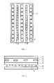
- FIG. 1 is a schematic top view of a solar photovoltaic-thermal system of the present invention
- FIG. 2 is a schematic cross-sectional view of the solar photovoltaic-thermal system of the present invention.
- FIG. 3 to FIG. 5 show light wavelength and transmission data of different examples of a long-waveband light reflecting layer in the present invention.
- a solar photovoltaic-thermal system comprising:
- the solar photovoltaic-thermal system of the present invention comprises a photovoltaic component 3, a heat exchanger 5.
- the arrows indicate the flow direction of the working fluid to be heated by the heat exchanger 5.
- the fluid flows to a heating system not shown in the drawings, such as a heating system of a building.
- the solar photovoltaic-thermal system of the present invention comprises a transparent glass front cover 1, a transparent encapsulating material 2 for encapsulating a plurality of photovoltaic components 3, transparent glass back sheet 4, the afore-mentioned heat exchanger 5, a light guide 6 and a light reflecting plate 7.
- the space enclosed by the light guides 6 and the light reflecting plate 7 forms a light collection cavity.
- the space between the transparent glass back sheet 4 and the light reflecting plate 7 is subdivided by the plurality of light guides 6, which are preferably disposed at regular spacings, into a plurality of light collection cavities, which accommodate a respective heat exchanger 5.
- the heat exchangers 5 are disposed in the middle of the associated light collection cavity and are fixed (or abut) the bottom surface of the transparent glass back sheet 4.
- FIG. 3 to FIG. 5 show light wavelength and transmission data of different examples of a long-waveband light reflecting layer in the present invention.
- the selected long-waveband light reflecting layers considered for Fig. 3 are respectively a multilayered structure of silver film/gallium zinc oxide (GZO) film/silver film.
- the multilayered structure considered for Fig. 4 is a multilayer structure consisting of silver film/GZO film/aluminum zinc oxide (AZO) film/GZO film/silver film.
- the alternating-layered structure considered for Fig. 5 consists of GZO and AZO (GZO/AZO/GZO/AZO/GZO/AZO/GZO/AZO/GZO/AZO/GZO/AZO/GZO/GZO). These layers are preferably used in the solar photovoltaic-thermal system of the present invention as explained in more detail in the following.
- the solar cell assembly of the present invention may be any type of solar cell assembly.
- the solar cell assembly of the present invention may include peripheral components such as an outer frame, an injunction box, lead wires, and a battery. All the peripheral components may be manufactured by means of conventional technology, and therefore are not described in any further detail in the present invention.
- a low reflective transparent glass plate is used, so as to provide sufficient light transmissive property and mechanical strength, such as compressive strength, tensile strength and hardness, and prevent moisture from entering the solar cell assembly.
- the encapsulating material used in the solar cell assembly of the present invention is mainly for fixing the photovoltaic component of the solar cell and providing physical protection to the photovoltaic component, such as resisting shock and preventing moisture from entering.
- the encapsulating layer in the solar cell assembly of the present invention may be made of any conventional material; currently, EVA is the most extensively used encapsulating material for a solar cell plate.
- EVA is a thermosetting resin, has properties such as high light transmission, heat resistance, low-temperature resistance, moisture resistance, and weather proofing after curing, has good adherence with metal, glass and plastic, and also has certain elasticity, shock resistance and heat conductivity, and therefore is an ideal solar cell encapsulating material.
- photovoltaic component in the solar cell assembly of the present invention which may be selected from various forms of photovoltaic components, such as a crystalline silicon photovoltaic component, a thin-film photovoltaic component, and a dye light-sensitive photovoltaic component.
- the solar photovoltaic-thermal system of the present invention at least one part of the irradiation area should not be covered by the photovoltaic component, so that light can penetrate the layer of the solar cell assembly and reach the light collection cavity at the bottom thereof, so as to heat the fluid in the heat exchanger.
- the proportion left uncovered may be adjusted to accommodate particular conditions of its implementation, such as the conversion efficiency of the photovoltaic component, duration and intensity of sunlight, and the demand for electric power relative to that for thermal power. Generally, it would be appropriate that the amount covered is from 30% to 80%, preferably from 40% to 60%.
- the solar photovoltaic-thermal system of the present invention has the configuration of the solar cell assembly and the heat exchanger as shown in FIG. 1 .
- the photovoltaic component in the solar cell assembly may be a double-facial photovoltaic component, such as HIT Double ® of SANYO Corporation, Japan, which can fully utilize the optical energy reflected by the light collection cavity back to the photovoltaic component.
- the back sheet in the solar cell assembly of the present invention simultaneously serves as the top cover of the light collection cavity, and therefore needs to have special properties. Firstly, the back sheet has to be transparent, so that light can enter the light collection cavity. Secondly, the back sheet is supported only by the outer frame and the light guide, leaving a large portion thereof suspended in the air, and therefore has to have excellent mechanical properties. Generally, an appropriate back sheet material should have compressive strength of at least about 120 MPa, bending strength of at least about 120 MPa and tensile strength of at least about 90 MPa.
- a novel type of physical tempered glass which may be made through treatment procedures such as aerodynamic heating and cooling, may be used as the back sheet glass of the present invention.
- this physical tempered glass may be made by performing heating in a aerodynamic-heating tempering furnace (such as a flatbed tempering furnace produced by LiSEC corporation) at a temperature ranging from about 600°C to about 750°C, preferably from 630°C to about 700°C, and then performing rapid cooling through, for example, an air nozzle.
- a aerodynamic-heating tempering furnace such as a flatbed tempering furnace produced by LiSEC corporation
- the term "aerodynamic heating” refers to a process of transferring heat to an object through high-temperature gas generated when the object and air or other gases move at a high relative velocity.
- the solar back sheet of most conventional solar cells is made of polyvinyl fluoride (such as Tedlar ® of DuPont Corporation, US). Such material does not have the requisite mechanical properties as described above, and therefore is not applicable to the present invention.
- Normal glass does not have the requisite mechanical properties, either (for example, normal glass only has a tensile strength of about 40MPa), and thus cannot be applied to the present invention.
- a conventional physically tempered glass might have sufficient mechanical properties, but must normally be over 3 millimeters thick to avoid deformation, which makes it heavy, and thus not only imposes an increased load on the light guide but also makes it unsuitable for mounting on the roof of a residential building.
- conventional chemically tempered glass it might meet the requisite mechanical properties and is not subject to the limitations imposed on thickness by machining.
- chemically tempered glass degrades very easily due to environmental factors, and has certain other disadvantages that limit its range of application, such as being difficult to coat, stripping easily and being costly.
- the solar heat collection assembly of the present invention is formed of a light collection cavity enclosed by the back sheet of a solar cell assembly, a light guide, and a light reflecting plate, and a heat exchanger therein.
- the main aim of the light collection cavity lies in that: the incident sunlight that enters is confined in the light collection cavity, and optical energy is converted into radiant heat through mechanisms such as scattering and reflecting so that the radiant heat is concentrated on the heat exchanger and heats the fluid therein.
- the temperature of the light collection cavity is higher than the temperature of the fluid in the heat exchanger, a part of the heat energy is transferred to the fluid through conduction.
- the light guide and the bottom-most light reflecting plate in the solar heat collection assembly of the present invention may be made of various materials, such as glass or plastic.
- the plastic material may be formed of one or more polymeric resin layers.
- the type of resin used for forming the polymeric resin layer is not particularly limited, and can be, for example, but not limited to, polyester resin, such as polyethylene terephthalate (PET) or polyethylene naphthalate (PEN); polyacrylate resin, such as polymethylmethacrylate (PMMA); polyolefin resin, such as polyethylene (PE) or polypropylene (PP); polystyrene resin; polycycloolefin resin; polyimide resin; polycarbonate resin; polyurethane resin; triacetate cellulose (TAC); polylactic acid; or a mixture thereof, and preferably is PET, PMMA, polycycloolefin resin, TAC, polylactic acid or a mixture thereof.
- PET polyethylene terephthalate
- PEN polyethylene naphthalate
- the surface shape of the light guide in the present invention is not particularly limited. However, its main purpose is to reflect the incident light onto the heat exchanger as much as possible, so it preferably has a plane with a slant angle (such as a side of a triangle), an arc surface or a parabolic surface.
- a surface of the light guide and a surface of the light reflecting plate may be covered with a reflecting layer.
- the primary function of the reflecting layer on the light guide and the light reflecting plate is to reflect full-waveband light, so the type of material employed is not particularly limited and preferably may be metal, such as silver, gold, aluminum or chromium; and a metal oxide or a non-metal material. Materials such as TiO 2 BaSO 4 , and Teflon have a white appearance, and therefore may provide more effective reflection of light, and are thus preferable materials.
- the reflecting layer may be bonded to the light guide or the light reflecting plate by means of any suitable method; for example, they can be bonded by using an adhesive.
- a preferable method is to directly deposit a metal on a glass substrate by utilizing methods such as physical vapor deposition. This method does not need any adhesive, so in addition to reducing manufacturing process steps, it avoids problems associated with deterioration of the adhesive. Such method is preferable in view of reliability.
- the light guide may be made of metals.
- the back of the back sheet of the solar cell assembly may be covered with a reflecting layer.
- the reflecting layer on the back of the back sheet has to be capable of selectively reflecting light.
- the incident sunlight is mainly short waveband, while the light reflected after irradiating the object is converted into long-waveband light, so the back of the back sheet of the solar cell assembly of the present invention is mostly preferably covered with a reflecting layer that mainly reflects long-waveband light.
- the long-waveband light reflecting layer is a multilayered structure formed primarily of a metal film and a transparent metal oxide film, and may employ any of the following types of design:
- Suitable highly reflective metal includes, for example, silver, gold, aluminum or chromium, and preferably silver.
- the suitable transparent metal oxide includes, for example, an indium tin oxide (ITO), an indium oxide plus titanium oxide (ITiO), an indium molybdenum oxide (IMO), a zinc oxide (ZnO), an indium gallium zinc oxide (IGZO), an AZO, a GZO, and an indium zinc oxide (IZO), and preferably GZO and AZO.
- ITO indium tin oxide
- ITiO indium oxide plus titanium oxide
- IMO indium molybdenum oxide
- ZnO zinc oxide
- IGZO indium gallium zinc oxide
- AZO indium gallium zinc oxide
- GZO AZO
- IZO indium zinc oxide
- the long-waveband light reflecting layer is a multilayered structure of silver film/GZO film/silver film and the light transmission-wavelength data thereof are as shown in FIG.
- the long-waveband light reflecting layer is an alternating multilayered structure (GZO/AZO/GZO/AZO/GZO/AZO/GZO/AZO/GZO/AZO/GZO/AZO/GZO/AZO/GZO/GZO/GZO) of GZO and AZO, and the light transmission-wavelength data thereof are as shown in FIG. 5 .
- each light collection cavity at least one heat exchanger should be provided to remove the heat energy in the cavity.
- the material of the heat exchanger used in the present invention has no special limitation, and may be made of a heat conducting material such as copper or stainless steel.
- the type of heat exchanger also has no limitation; for example, a column tube heat exchanger or a spiral-tube heat exchanger may be used.
- the heat exchanger may be coated or covered with a dark heat absorbing material, so as to increase heat transfer efficiency.
- the fluid in the heat exchanger may be any suitable fluid, preferably one with a high specific heat, such as water. However, a gas is also possible.
- the solar photovoltaic-thermal system of the present invention may have the cross-section configuration as shown in FIG. 2 .
Landscapes
- Physics & Mathematics (AREA)
- Condensed Matter Physics & Semiconductors (AREA)
- Electromagnetism (AREA)
- General Physics & Mathematics (AREA)
- Engineering & Computer Science (AREA)
- Computer Hardware Design (AREA)
- Microelectronics & Electronic Packaging (AREA)
- Power Engineering (AREA)
- Photovoltaic Devices (AREA)
Abstract
Description
- The present invention relates to a solar photovoltaic-thermal system, and more particularly to an integrated system having a solar heat collection assembly with a light collection cavity and having a double-glass solar cell component.
- Solar energy is the most prevalently used environmentally friendly source of energy. Generally, there are two principal manners by which solar energy is utilized. In the first manner, a solar heat collector directly absorbs radiant heat from sunlight, and in the second manner, solar energy is converted into electric energy by utilizing the photovoltaic effect of a solar cell.
- Solar heat collectors are most commonly employed in solar heaters, which are generally operated by guiding sunlight to a water pipe through a condensing reflecting plate or a vacuum heat collector, so that optical energy from sunlight is converted into heat energy to heat water in the pipe.
- The solar cell assembly is generally formed by combining a multilayered structure of glass, ethylene vinyl acetate (EVA), a photovoltaic component and a solar energy back sheet, and peripheral components such as an outer frame made of aluminum, galvanized steel sheet, wood and synthetic materials (such as polyethylene (PE), polypropylene (PP) and ethylene propylene rubber), a junction box, lead wires, and a battery. Under sunlight irradiation, the solar cell assembly outputs a certain working voltage and working current through photovoltaic effect. However, efficiency of the solar cell assembly is limited, and a large part of solar energy is converted into heat energy and accumulated in a solar energy component, which results in increased temperature of the solar energy component and causes damage to the solar cell assembly and decrease in the total output power.
- It is an object of the present invention to provide a highly efficient and reliable solar photovoltaic-thermal system.
- This problem is solved by a solar photovoltaic-thermal system as claimed by
claim 1. Further advantageous embodiments are the subject-matter of the dependent claims. - Because according to the present invention the solar cell assembly and the solar heat collector can be integrated to form a solar photovoltaic-thermal system, not only can solar energy be utilized more effectively, but also the heat energy accumulated by the solar energy component can be effectively reduced, thereby avoiding the aforementioned problems. Moreover, according to the present invention the solar cell assembly and the solar heat collector can be integrated to form a solar photovoltaic-thermal system. Thus, a reduced amount of materials is required to form a solar photovoltaic-thermal system of the present invention, which is economically beneficial.
- According to the present invention there is provided a solar photovoltaic-thermal system comprising:
- a solar cell assembly comprising a transparent glass front cover, a transparent encapsulating material, a transparent glass back sheet and photovoltaic components encapsulated by the transparent encapsulating material, wherein a gap allowing light penetration is provided between adjacent photovoltaic components;
- a plurality of light guides disposed below the transparent glass back sheet of the solar cell assembly;
- a light reflecting plate disposed below the solar cell assembly and the light guide, wherein the light reflecting plate, the two adjacent light guides and the transparent glass back sheet form a light collection cavity; and
- a heat exchanger disposed in the light collection cavity.
- The invention will be described according to the appended drawings, in which:
-
FIG. 1 is a schematic top view of a solar photovoltaic-thermal system of the present invention; -
FIG. 2 is a schematic cross-sectional view of the solar photovoltaic-thermal system of the present invention; and -
FIG. 3 to FIG. 5 show light wavelength and transmission data of different examples of a long-waveband light reflecting layer in the present invention. - In this context, unless otherwise limited, a singular term (such as "a") also includes a plural form thereof. In this context, all embodiments and exemplary terms (for example, "such as") only aim at making the present invention more prominent, but are not intended to limit the scope of the present invention; terms in this specification should not be construed as implying that any component not claimed may form a necessary component for implementing the present invention.
- According to the present invention there is provided a solar photovoltaic-thermal system comprising:
- a solar cell assembly comprising a transparent glass front cover, a transparent encapsulating material, a transparent glass back sheet and photovoltaic components encapsulated by the transparent encapsulating material, wherein a gap allowing light penetration is provided between adjacent photovoltaic components;
- a plurality of light guides disposed below the transparent glass back sheet of the solar cell assembly;
- a light reflecting plate disposed below the solar cell assembly and the light guide, wherein the light reflecting plate, the two adjacent light guides and the transparent glass back sheet form a light collection cavity; and
- a heat exchanger disposed in the light collection cavity.
- More specifically, as shown in the top view of
Fig. 1 , the solar photovoltaic-thermal system of the present invention comprises aphotovoltaic component 3, aheat exchanger 5. The arrows indicate the flow direction of the working fluid to be heated by theheat exchanger 5. The fluid flows to a heating system not shown in the drawings, such as a heating system of a building. - As shown in the schematic cross-sectional view of
Fig. 2 , the solar photovoltaic-thermal system of the present invention comprises a transparentglass front cover 1, a transparentencapsulating material 2 for encapsulating a plurality ofphotovoltaic components 3, transparent glass back sheet 4, the afore-mentionedheat exchanger 5, alight guide 6 and a light reflectingplate 7. The space enclosed by thelight guides 6 and thelight reflecting plate 7 forms a light collection cavity. More specifically, the space between the transparent glass back sheet 4 and thelight reflecting plate 7 is subdivided by the plurality oflight guides 6, which are preferably disposed at regular spacings, into a plurality of light collection cavities, which accommodate arespective heat exchanger 5. As shown inFig. 2 , preferably theheat exchangers 5 are disposed in the middle of the associated light collection cavity and are fixed (or abut) the bottom surface of the transparent glass back sheet 4. -
FIG. 3 to FIG. 5 show light wavelength and transmission data of different examples of a long-waveband light reflecting layer in the present invention. The selected long-waveband light reflecting layers considered forFig. 3 are respectively a multilayered structure of silver film/gallium zinc oxide (GZO) film/silver film. The multilayered structure considered forFig. 4 is a multilayer structure consisting of silver film/GZO film/aluminum zinc oxide (AZO) film/GZO film/silver film. The alternating-layered structure considered forFig. 5 consists of GZO and AZO (GZO/AZO/GZO/AZO/GZO/AZO/GZO/AZO/GZO/AZO/GZO). These layers are preferably used in the solar photovoltaic-thermal system of the present invention as explained in more detail in the following. - Parts and technical features of the solar photovoltaic-thermal system of the present invention are further illustrated below.
- The solar cell assembly of the present invention may be any type of solar cell assembly. In addition to the front cover, the encapsulating material, the photovoltaic component, and the back sheet, the solar cell assembly of the present invention may include peripheral components such as an outer frame, an injunction box, lead wires, and a battery. All the peripheral components may be manufactured by means of conventional technology, and therefore are not described in any further detail in the present invention.
- No special limitation is imposed on the front cover used in the solar cell assembly of the present invention; generally, a low reflective transparent glass plate is used, so as to provide sufficient light transmissive property and mechanical strength, such as compressive strength, tensile strength and hardness, and prevent moisture from entering the solar cell assembly.
- The encapsulating material used in the solar cell assembly of the present invention is mainly for fixing the photovoltaic component of the solar cell and providing physical protection to the photovoltaic component, such as resisting shock and preventing moisture from entering. The encapsulating layer in the solar cell assembly of the present invention may be made of any conventional material; currently, EVA is the most extensively used encapsulating material for a solar cell plate. EVA is a thermosetting resin, has properties such as high light transmission, heat resistance, low-temperature resistance, moisture resistance, and weather proofing after curing, has good adherence with metal, glass and plastic, and also has certain elasticity, shock resistance and heat conductivity, and therefore is an ideal solar cell encapsulating material.
- No particular limitation is imposed on the photovoltaic component in the solar cell assembly of the present invention, which may be selected from various forms of photovoltaic components, such as a crystalline silicon photovoltaic component, a thin-film photovoltaic component, and a dye light-sensitive photovoltaic component.
- In the solar photovoltaic-thermal system of the present invention, at least one part of the irradiation area should not be covered by the photovoltaic component, so that light can penetrate the layer of the solar cell assembly and reach the light collection cavity at the bottom thereof, so as to heat the fluid in the heat exchanger. The proportion left uncovered may be adjusted to accommodate particular conditions of its implementation, such as the conversion efficiency of the photovoltaic component, duration and intensity of sunlight, and the demand for electric power relative to that for thermal power. Generally, it would be appropriate that the amount covered is from 30% to 80%, preferably from 40% to 60%. In a specific embodiment, the solar photovoltaic-thermal system of the present invention has the configuration of the solar cell assembly and the heat exchanger as shown in
FIG. 1 . - In a specific embodiment of the present invention, the photovoltaic component in the solar cell assembly may be a double-facial photovoltaic component, such as HIT Double® of SANYO Corporation, Japan, which can fully utilize the optical energy reflected by the light collection cavity back to the photovoltaic component.
- The back sheet in the solar cell assembly of the present invention simultaneously serves as the top cover of the light collection cavity, and therefore needs to have special properties. Firstly, the back sheet has to be transparent, so that light can enter the light collection cavity. Secondly, the back sheet is supported only by the outer frame and the light guide, leaving a large portion thereof suspended in the air, and therefore has to have excellent mechanical properties. Generally, an appropriate back sheet material should have compressive strength of at least about 120 MPa, bending strength of at least about 120 MPa and tensile strength of at least about 90 MPa.
- A novel type of physical tempered glass, which may be made through treatment procedures such as aerodynamic heating and cooling, may be used as the back sheet glass of the present invention. Specifically, this physical tempered glass may be made by performing heating in a aerodynamic-heating tempering furnace (such as a flatbed tempering furnace produced by LiSEC corporation) at a temperature ranging from about 600°C to about 750°C, preferably from 630°C to about 700°C, and then performing rapid cooling through, for example, an air nozzle. In this context, the term "aerodynamic heating" refers to a process of transferring heat to an object through high-temperature gas generated when the object and air or other gases move at a high relative velocity. When the tempered glass is heated in the aerodynamic heating manner, the glass and the tempering furnace do not directly contact, so the glass is not deformed, and is suitable for thin glass. For a more detailed physical tempered glass preparation method, reference may be made to the content in the application of Chinese Patent Application No.
201110198526.1 US Patent Publication No. 2013/0008500 A1 ), the whole content of which is hereby expressly incorporated by reference and part of the disclosure of the present application. - The solar back sheet of most conventional solar cells is made of polyvinyl fluoride (such as Tedlar® of DuPont Corporation, US). Such material does not have the requisite mechanical properties as described above, and therefore is not applicable to the present invention.
- Normal glass does not have the requisite mechanical properties, either (for example, normal glass only has a tensile strength of about 40MPa), and thus cannot be applied to the present invention. Moreover, a conventional physically tempered glass might have sufficient mechanical properties, but must normally be over 3 millimeters thick to avoid deformation, which makes it heavy, and thus not only imposes an increased load on the light guide but also makes it unsuitable for mounting on the roof of a residential building. As for conventional chemically tempered glass, it might meet the requisite mechanical properties and is not subject to the limitations imposed on thickness by machining. However, chemically tempered glass degrades very easily due to environmental factors, and has certain other disadvantages that limit its range of application, such as being difficult to coat, stripping easily and being costly.
- The solar heat collection assembly of the present invention is formed of a light collection cavity enclosed by the back sheet of a solar cell assembly, a light guide, and a light reflecting plate, and a heat exchanger therein.
- The main aim of the light collection cavity lies in that: the incident sunlight that enters is confined in the light collection cavity, and optical energy is converted into radiant heat through mechanisms such as scattering and reflecting so that the radiant heat is concentrated on the heat exchanger and heats the fluid therein. In addition, because the temperature of the light collection cavity is higher than the temperature of the fluid in the heat exchanger, a part of the heat energy is transferred to the fluid through conduction.
- The light guide and the bottom-most light reflecting plate in the solar heat collection assembly of the present invention may be made of various materials, such as glass or plastic. The plastic material may be formed of one or more polymeric resin layers. The type of resin used for forming the polymeric resin layer is not particularly limited, and can be, for example, but not limited to, polyester resin, such as polyethylene terephthalate (PET) or polyethylene naphthalate (PEN); polyacrylate resin, such as polymethylmethacrylate (PMMA); polyolefin resin, such as polyethylene (PE) or polypropylene (PP); polystyrene resin; polycycloolefin resin; polyimide resin; polycarbonate resin; polyurethane resin; triacetate cellulose (TAC); polylactic acid; or a mixture thereof, and preferably is PET, PMMA, polycycloolefin resin, TAC, polylactic acid or a mixture thereof.
- The surface shape of the light guide in the present invention is not particularly limited. However, its main purpose is to reflect the incident light onto the heat exchanger as much as possible, so it preferably has a plane with a slant angle (such as a side of a triangle), an arc surface or a parabolic surface.
- In order to increase heat collection efficiency of the light collection cavity, a surface of the light guide and a surface of the light reflecting plate may be covered with a reflecting layer. The primary function of the reflecting layer on the light guide and the light reflecting plate is to reflect full-waveband light, so the type of material employed is not particularly limited and preferably may be metal, such as silver, gold, aluminum or chromium; and a metal oxide or a non-metal material. Materials such as TiO2 BaSO4, and Teflon have a white appearance, and therefore may provide more effective reflection of light, and are thus preferable materials. The reflecting layer may be bonded to the light guide or the light reflecting plate by means of any suitable method; for example, they can be bonded by using an adhesive. When the reflecting layer is made of a metal material while the light guide or the light reflecting plate is made of a glass material, a preferable method is to directly deposit a metal on a glass substrate by utilizing methods such as physical vapor deposition. This method does not need any adhesive, so in addition to reducing manufacturing process steps, it avoids problems associated with deterioration of the adhesive. Such method is preferable in view of reliability.
- Alternatively, the light guide may be made of metals.
- Likewise, in order to improve effectiveness of the light collection cavity, the back of the back sheet of the solar cell assembly may be covered with a reflecting layer. However, in order to allow sunlight to enter the light collection cavity, the reflecting layer on the back of the back sheet has to be capable of selectively reflecting light. Further, the incident sunlight is mainly short waveband, while the light reflected after irradiating the object is converted into long-waveband light, so the back of the back sheet of the solar cell assembly of the present invention is mostly preferably covered with a reflecting layer that mainly reflects long-waveband light.
- Generally, the long-waveband light reflecting layer is a multilayered structure formed primarily of a metal film and a transparent metal oxide film, and may employ any of the following types of design:
- (1) highly reflective metal film layer/transparent metal oxide film layer/highly reflective metal film layer;
- (2) highly reflective metal film layer/transparent metal oxide film layer (A)/transparent metal oxide film layer (B)/transparent metal oxide film layer (A)/highly reflective metal film layer, where the optical refractive index of the transparent metal oxide film layer A is greater than the optical refractive index of the transparent metal oxide film layer B; and
- (3) repetitive alternating multilayered structure of different transparent metal oxide film layers.
- Suitable highly reflective metal includes, for example, silver, gold, aluminum or chromium, and preferably silver. The suitable transparent metal oxide includes, for example, an indium tin oxide (ITO), an indium oxide plus titanium oxide (ITiO), an indium molybdenum oxide (IMO), a zinc oxide (ZnO), an indium gallium zinc oxide (IGZO), an AZO, a GZO, and an indium zinc oxide (IZO), and preferably GZO and AZO. As a specific example (1), the long-waveband light reflecting layer is a multilayered structure of silver film/GZO film/silver film and the light transmission-wavelength data thereof are as shown in
FIG. 3 ; as a specific example (2), the long-waveband light reflecting layer is a multilayered structure of silver film/GZO (n = 2.1) film/AZO (n = 1.9) film/GZO (n = 2.1) film/silver film, and the light transmission-wavelength data thereof are as shown inFIG. 4 . As a specific example (3), the long-waveband light reflecting layer is an alternating multilayered structure (GZO/AZO/GZO/AZO/GZO/AZO/GZO/AZO/GZO/AZO/GZO) of GZO and AZO, and the light transmission-wavelength data thereof are as shown inFIG. 5 . - In each light collection cavity, at least one heat exchanger should be provided to remove the heat energy in the cavity. The material of the heat exchanger used in the present invention has no special limitation, and may be made of a heat conducting material such as copper or stainless steel. The type of heat exchanger also has no limitation; for example, a column tube heat exchanger or a spiral-tube heat exchanger may be used. The heat exchanger may be coated or covered with a dark heat absorbing material, so as to increase heat transfer efficiency.
- The fluid in the heat exchanger may be any suitable fluid, preferably one with a high specific heat, such as water. However, a gas is also possible.
- In a specific embodiment, the solar photovoltaic-thermal system of the present invention may have the cross-section configuration as shown in
FIG. 2 .
Claims (11)
- A solar photovoltaic-thermal system comprising:a solar cell assembly comprising a transparent glass front cover (1), a transparent encapsulating material (2), a transparent glass back sheet (4) and a photovoltaic component (3) encapsulated by the transparent encapsulating material (2);a plurality of light guides (6), located below the transparent glass back sheet (4) of the solar cell assembly; anda light reflecting plate (7) disposed below the solar cell assembly and the light guide, wherein the light reflecting plate (7), two adjacent light guides (6) and the transparent glass back sheet (4) form a light collection cavity; anda heat exchanger (5) disposed in the light collection cavity.
- The solar photovoltaic-thermal system according to Claim 1, wherein the transparent glass back sheet (4) is physical tempered glass.
- The solar photovoltaic-thermal system according to Claim 2, wherein the physical tempered glass has compressive strength ranging from about 120 MPa to about 300 MPa, bending strength ranging from about 120 MPa to about 300 MPa and tensile strength ranging from about 90 MPa to about 180 MPa.
- The solar photovoltaic-thermal system according to any of the preceding claims, wherein the surface of the transparent glass back sheet (4) facing the light collection cavity is covered with a long-waveband light reflecting layer.
- The solar photovoltaic-thermal system according to Claim 4, wherein the long-waveband light reflecting layer is a multilayered structure of highly reflective metal film/transparent metal oxide film/highly reflective metal film.
- The solar photovoltaic-thermal system according to Claim 5, wherein the highly reflective metal film is a silver film, and the transparent metal oxide film is a zinc oxide film.
- The solar photovoltaic-thermal system according to Claim 4, wherein the long-waveband light reflecting layer is a multilayered structure of highly reflective metal film/transparent metal oxide film (A)/transparent metal oxide film (B)/transparent metal oxide film (A)/highly reflective metal film, and wherein the optical refractive index of the transparent metal oxide film (A) is greater than the optical refractive index of the transparent metal oxide film (B).
- The solar photovoltaic-thermal system according to Claim 7, wherein the highly reflective metal film of the long-waveband light reflecting layer is silver, the transparent metal oxide film (A) is a gallium zinc oxide (GZO) film, and the transparent metal oxide film (B) is an aluminum zinc oxide (AZO) film.
- The solar photovoltaic-thermal system according to any of claims 4 to 8, wherein the long-waveband light reflecting layer is bonded to the transparent glass back sheet by direct deposition.
- The solar photovoltaic-thermal system according to any of the preceding claims, wherein the light reflecting plate (7) or the light guide (6) or both are covered with a reflecting layer on the surfaces facing the light collection cavity.
- The solar photovoltaic-thermal system according to Claim 10, wherein the reflecting layer is a metal material selected from silver, gold, aluminum or chromium or a metal oxide or a non-metal material selected from TiO2, BaSO4 or Teflon.
Applications Claiming Priority (1)
| Application Number | Priority Date | Filing Date | Title |
|---|---|---|---|
| CN201210127145.9A CN103378199B (en) | 2012-04-26 | 2012-04-26 | Solar energy hot systems |
Publications (3)
| Publication Number | Publication Date |
|---|---|
| EP2657988A2 true EP2657988A2 (en) | 2013-10-30 |
| EP2657988A3 EP2657988A3 (en) | 2015-09-30 |
| EP2657988B1 EP2657988B1 (en) | 2017-06-07 |
Family
ID=48193131
Family Applications (1)
| Application Number | Title | Priority Date | Filing Date |
|---|---|---|---|
| EP13165493.1A Active EP2657988B1 (en) | 2012-04-26 | 2013-04-26 | Solar photovoltaic-thermal system |
Country Status (5)
| Country | Link |
|---|---|
| US (1) | US10461206B2 (en) |
| EP (1) | EP2657988B1 (en) |
| JP (1) | JP6351209B2 (en) |
| CN (1) | CN103378199B (en) |
| TW (1) | TWI565918B (en) |
Cited By (2)
| Publication number | Priority date | Publication date | Assignee | Title |
|---|---|---|---|---|
| CN110034197A (en) * | 2018-01-10 | 2019-07-19 | 协鑫能源工程有限公司 | Photovoltaic module |
| EP3771091A4 (en) * | 2018-03-20 | 2021-12-01 | Kaneka Corporation | Glass building material |
Families Citing this family (16)
| Publication number | Priority date | Publication date | Assignee | Title |
|---|---|---|---|---|
| US9714756B2 (en) | 2013-03-15 | 2017-07-25 | Morgan Solar Inc. | Illumination device |
| US9960303B2 (en) | 2013-03-15 | 2018-05-01 | Morgan Solar Inc. | Sunlight concentrating and harvesting device |
| US9595627B2 (en) | 2013-03-15 | 2017-03-14 | John Paul Morgan | Photovoltaic panel |
| US9464782B2 (en) | 2013-03-15 | 2016-10-11 | Morgan Solar Inc. | Light panel, optical assembly with improved interface and light panel with improved manufacturing tolerances |
| TWM458534U (en) * | 2013-03-20 | 2013-08-01 | Sunvalue Co Ltd | Solar power generation bricks |
| KR101400206B1 (en) * | 2013-11-20 | 2014-05-28 | 주식회사 이건창호 | Method for manufacturing solar cell structure for thermal insulation |
| TWI532205B (en) * | 2014-01-17 | 2016-05-01 | 王立康 | A Method for Fabricating Crystalline Silicon Solar Cell Having Local Rear Contacts and Passivation Layer and the Device |
| KR101604824B1 (en) | 2014-04-25 | 2016-03-18 | 최진곤 | Hybrid solar panel for solar energy generation device |
| JP6552893B2 (en) * | 2015-07-07 | 2019-07-31 | 日清紡メカトロニクス株式会社 | Hybrid solar cell module |
| CN105895719B (en) * | 2016-05-13 | 2017-12-26 | 广东大粤新能源科技股份有限公司 | A kind of solar photovoltaic assembly |
| DE202016004934U1 (en) * | 2016-08-13 | 2017-11-14 | Consolar Solare Energiesysteme Gmbh | Photovoltaic thermal module with air heat exchanger |
| CN107070398B (en) * | 2017-05-31 | 2019-08-09 | 刘海明 | One kind is based on water flow heat absorption circulating solar energy solar panel |
| CN108417655B (en) * | 2018-03-28 | 2024-07-09 | 盐城天合国能光伏科技有限公司 | Thin type component of reflective heat-dissipation efficient flat-plate solar cell |
| CN108417654B (en) * | 2018-03-28 | 2024-07-09 | 盐城天合国能光伏科技有限公司 | Thin type assembly of heat dissipation efficient flat-plate solar cell |
| CN111464131B (en) * | 2019-01-18 | 2022-03-08 | 北京航空航天大学 | Wind-resistant anti-freezing high-concentration photovoltaic-photo-thermal solar comprehensive utilization system |
| CN115164596B (en) * | 2022-06-15 | 2024-08-16 | 成都中建材光电材料有限公司 | Activation treatment device and activation treatment method for thin film solar cell |
Citations (1)
| Publication number | Priority date | Publication date | Assignee | Title |
|---|---|---|---|---|
| US20130008500A1 (en) | 2011-07-06 | 2013-01-10 | Changzhou Almaden Co., Ltd. | Physical tempered glass, solar cover plate, solar backsheet and solar panel |
Family Cites Families (54)
| Publication number | Priority date | Publication date | Assignee | Title |
|---|---|---|---|---|
| US3866285A (en) * | 1974-03-01 | 1975-02-18 | Dow Corning | Method of constructing a solar energy collector |
| JPS53109237A (en) * | 1977-03-03 | 1978-09-22 | Toshio Nakatani | High temperature solar heater |
| US4395582A (en) * | 1979-03-28 | 1983-07-26 | Gibbs & Hill, Inc. | Combined solar conversion |
| US4411490A (en) * | 1980-08-18 | 1983-10-25 | Maurice Daniel | Apparatus for collecting, distributing and utilizing solar radiation |
| JPS58135685A (en) * | 1982-02-08 | 1983-08-12 | Toshiba Corp | Hybrid type solar energy collector |
| JPS6041764U (en) * | 1983-08-31 | 1985-03-25 | 矢崎総業株式会社 | heat collector |
| US4892593A (en) * | 1984-10-09 | 1990-01-09 | Lew Hyok S | Solar trap |
| JPH03267655A (en) * | 1990-03-15 | 1991-11-28 | Sanyo Electric Co Ltd | Solar energy collector |
| CN2124432U (en) * | 1992-06-02 | 1992-12-09 | 赵贵 | Focus-thermal tube type solar heat collector |
| JPH06201197A (en) * | 1992-10-08 | 1994-07-19 | Kokusai Gijutsu Kaihatsu Kk | Solar heat collecting device |
| US6057504A (en) * | 1994-10-05 | 2000-05-02 | Izumi; Hisao | Hybrid solar collector for generating electricity and heat by separating solar rays into long wavelength and short wavelength |
| JP3698215B2 (en) * | 1995-01-23 | 2005-09-21 | 勝泰 河野 | Light receiving element |
| JP2001311564A (en) * | 2000-04-27 | 2001-11-09 | Yazaki Corp | Heat collector with solar cell |
| AUPR174800A0 (en) * | 2000-11-29 | 2000-12-21 | Australian National University, The | Semiconductor processing |
| JP2003218367A (en) * | 2002-01-22 | 2003-07-31 | Fuji Photo Film Co Ltd | Solar battery unit |
| DE10322048A1 (en) * | 2002-05-16 | 2003-11-27 | Manfred Jezerkowsky | Thermal/electric power production device for converting solar energy has a module with an absorber for yielding thermal energy and a solar module for producing electric energy |
| JP2004205062A (en) * | 2002-12-24 | 2004-07-22 | Takeo Saito | Light-concentrating solar water heater |
| JP2004317117A (en) * | 2003-04-02 | 2004-11-11 | Showa Denko Kk | Solar heat collector with solar power generation function |
| US7241506B2 (en) * | 2003-06-10 | 2007-07-10 | Cardinal Cg Company | Corrosion-resistant low-emissivity coatings |
| US7817567B2 (en) * | 2003-07-28 | 2010-10-19 | Jds Uniphase Corporation | Troubleshooting a specific voice over internet protocol (VOIP) telephone call transmitted over a communications network |
| US20050161074A1 (en) * | 2003-12-16 | 2005-07-28 | Paul Garvison | Photovoltaic module mounting unit and system |
| DE102004022629B9 (en) * | 2004-05-07 | 2008-09-04 | Schott Ag | Flooded lithium aluminosilicate flat glass with high temperature resistance, which can be preloaded chemically and thermally and its use |
| JP4841128B2 (en) * | 2004-09-28 | 2011-12-21 | 京セラ株式会社 | Photoelectric conversion device and photovoltaic device using the same |
| US20080115825A1 (en) * | 2006-09-20 | 2008-05-22 | Patel Rajen M | Electronic Device Module Comprising an Ethylene Multi-Block Copolymer |
| JP4851953B2 (en) * | 2007-02-07 | 2012-01-11 | 株式会社日立製作所 | Optical member |
| CN101319748A (en) * | 2007-06-07 | 2008-12-10 | 张玉良 | Vacuum controllable heat preservation method and solar heat collection and comprehensive utilization method |
| US20090014868A1 (en) * | 2007-07-10 | 2009-01-15 | International Business Machines Corporation | Manufacturing ic chip in portions for later combining, and related structure |
| KR101405933B1 (en) * | 2007-07-12 | 2014-06-12 | 엘지전자 주식회사 | Portable terminal and method for displaying position information in the portable terminal |
| EP2201309A4 (en) * | 2007-09-10 | 2010-12-01 | Banyan Energy Inc | Compact optics for concentration, aggregation and illumination of light energy |
| JP5331325B2 (en) * | 2007-09-28 | 2013-10-30 | 旭ファイバーグラス株式会社 | Solar cell module |
| WO2009093780A1 (en) * | 2008-01-24 | 2009-07-30 | Hae Sung Solar Co., Ltd. | Solar cell modules and the manufacturing method thereof |
| KR20100127775A (en) * | 2008-02-12 | 2010-12-06 | 퀄컴 엠이엠스 테크놀로지스, 인크. | Dual layer thin film holographic solar concentrator/collector |
| TWI370229B (en) * | 2008-03-21 | 2012-08-11 | Hon Hai Prec Ind Co Ltd | Solar collector |
| JP4459286B2 (en) * | 2008-08-08 | 2010-04-28 | 防衛省技術研究本部長 | Infrared detector |
| FR2936862B1 (en) * | 2008-10-02 | 2013-02-15 | Suez Environnement | DEVICE FOR GENERATING ENERGY FROM SOLAR RADIATION. |
| FR2940271B1 (en) * | 2008-12-22 | 2011-10-21 | Saint Gobain | SUBSTRATE WITH STACK WITH THERMAL PROPERTIES AND ABSORBENT LAYER (S) |
| TW201036185A (en) * | 2009-03-27 | 2010-10-01 | tong-qin Su | Thermal collection apparatus of solar power generation and thermal collection unit of power generation |
| SI23059A (en) * | 2009-05-25 | 2010-11-30 | Hrovatiäś@Igor | Collector for collecting and converting solar energy |
| JP2011000012A (en) * | 2009-06-17 | 2011-01-06 | Nakahara Kodenshi Kenkyusho:Kk | Plant factory |
| US20100326520A1 (en) * | 2009-06-29 | 2010-12-30 | Auria Solar Co., Ltd. | Thin film solar cell and manufacturing method thereof |
| CN201463295U (en) * | 2009-07-01 | 2010-05-12 | 山东力诺瑞特新能源有限公司 | Intermediate-temperature solar heat collector |
| US8108970B2 (en) * | 2009-07-28 | 2012-02-07 | Shin Zu Shing Co., Ltd. | Hinge mechanism and an electronic device therewith |
| JP2011066292A (en) * | 2009-09-18 | 2011-03-31 | Mitsubishi Heavy Ind Ltd | Solar cell panel |
| US9029683B2 (en) * | 2009-10-16 | 2015-05-12 | Soleeva Solar, Inc. | Self-contained, multi-fluid energy conversion and management system for converting solar energy to electric and thermal energy |
| IL205146A (en) * | 2010-02-02 | 2017-02-28 | T O U Millennium Electric Ltd | Solar paneland method for its manufacture |
| CA2936099C (en) * | 2010-02-17 | 2017-06-13 | Macdonald, Dettwiler And Associates Inc. | Scalable common interface plate system for robot |
| JP2011198825A (en) * | 2010-03-17 | 2011-10-06 | Ntt Docomo Inc | Solar energy generator |
| JP2013528951A (en) * | 2010-06-04 | 2013-07-11 | ダウ グローバル テクノロジーズ エルエルシー | Electronic device module comprising homogeneous polyolefin copolymer and adhesion-enhanced graft polymer membrane |
| JP2012007420A (en) * | 2010-06-25 | 2012-01-12 | Lic Co Ltd | Solar heat absorption panel and roof structure for building |
| US20120000508A1 (en) * | 2010-07-02 | 2012-01-05 | Du Pont Apollo Limited | Thermal device and photovoltaic module having the same |
| US20120024365A1 (en) * | 2010-07-27 | 2012-02-02 | Alliance For Sustainable Energy, Llc | Solar energy systems |
| US20120160302A1 (en) * | 2010-12-27 | 2012-06-28 | Jeffrey Michael Citron | Trough shaped fresnel reflector solar concentrator |
| CN201918411U (en) * | 2010-12-31 | 2011-08-03 | 浙江梅地亚新能源科技有限公司 | Flat-plate photovoltaic and photo-thermal complementary solar component |
| JP5617690B2 (en) * | 2011-02-24 | 2014-11-05 | 三洋電機株式会社 | Solar cell module manufacturing method and solar cell module |
-
2012
- 2012-04-26 CN CN201210127145.9A patent/CN103378199B/en active Active
-
2013
- 2013-04-26 JP JP2013093501A patent/JP6351209B2/en active Active
- 2013-04-26 US US13/871,236 patent/US10461206B2/en active Active
- 2013-04-26 TW TW102115209A patent/TWI565918B/en active
- 2013-04-26 EP EP13165493.1A patent/EP2657988B1/en active Active
Patent Citations (1)
| Publication number | Priority date | Publication date | Assignee | Title |
|---|---|---|---|---|
| US20130008500A1 (en) | 2011-07-06 | 2013-01-10 | Changzhou Almaden Co., Ltd. | Physical tempered glass, solar cover plate, solar backsheet and solar panel |
Cited By (2)
| Publication number | Priority date | Publication date | Assignee | Title |
|---|---|---|---|---|
| CN110034197A (en) * | 2018-01-10 | 2019-07-19 | 协鑫能源工程有限公司 | Photovoltaic module |
| EP3771091A4 (en) * | 2018-03-20 | 2021-12-01 | Kaneka Corporation | Glass building material |
Also Published As
| Publication number | Publication date |
|---|---|
| CN103378199B (en) | 2018-11-16 |
| EP2657988B1 (en) | 2017-06-07 |
| US20130284237A1 (en) | 2013-10-31 |
| TW201344127A (en) | 2013-11-01 |
| US10461206B2 (en) | 2019-10-29 |
| TWI565918B (en) | 2017-01-11 |
| JP6351209B2 (en) | 2018-07-04 |
| JP2013229609A (en) | 2013-11-07 |
| CN103378199A (en) | 2013-10-30 |
| EP2657988A3 (en) | 2015-09-30 |
Similar Documents
| Publication | Publication Date | Title |
|---|---|---|
| EP2657988B1 (en) | Solar photovoltaic-thermal system | |
| EP2693101A1 (en) | Solar lighting system | |
| US8039731B2 (en) | Photovoltaic concentrator for solar energy system | |
| US20140326306A1 (en) | Highly efficient solar cell module | |
| US10181815B2 (en) | Receiver for PV/T solar energy systems | |
| US10594256B2 (en) | Photovoltaic thermal collector | |
| JP2013229609A5 (en) | ||
| US20150155410A1 (en) | High efficiency double-glass solar modules | |
| JP5218670B2 (en) | Solar cell module | |
| JP5212307B2 (en) | Solar cell module | |
| WO2014180019A1 (en) | Solar module | |
| CN115911140A (en) | High-light-transmission and water vapor transmission-resistant photovoltaic module and preparation method and application thereof | |
| JP2013115216A (en) | Solar cell backside sheet and solar cell module | |
| CN209963067U (en) | Photovoltaic module | |
| JP6086778B2 (en) | Solar cell prism member and solar cell module | |
| CN108417654B (en) | Thin type assembly of heat dissipation efficient flat-plate solar cell | |
| CN207250537U (en) | A kind of solar cell module | |
| KR20120035294A (en) | Solar cell module | |
| JP6693828B2 (en) | Solar cells and solar cell modules | |
| JPH03267655A (en) | Solar energy collector | |
| WO2010073932A1 (en) | Solar cell module | |
| TWI814224B (en) | Photovoltaic module with light guide structure | |
| CN111081801B (en) | Lighting and power generation integrated glass with adjustable radiation transmittance | |
| CN108417655B (en) | Thin type component of reflective heat-dissipation efficient flat-plate solar cell | |
| JP2012084741A (en) | Solar cell module |
Legal Events
| Date | Code | Title | Description |
|---|---|---|---|
| PUAI | Public reference made under article 153(3) epc to a published international application that has entered the european phase |
Free format text: ORIGINAL CODE: 0009012 |
|
| AK | Designated contracting states |
Kind code of ref document: A2 Designated state(s): AL AT BE BG CH CY CZ DE DK EE ES FI FR GB GR HR HU IE IS IT LI LT LU LV MC MK MT NL NO PL PT RO RS SE SI SK SM TR |
|
| AX | Request for extension of the european patent |
Extension state: BA ME |
|
| PUAL | Search report despatched |
Free format text: ORIGINAL CODE: 0009013 |
|
| AK | Designated contracting states |
Kind code of ref document: A3 Designated state(s): AL AT BE BG CH CY CZ DE DK EE ES FI FR GB GR HR HU IE IS IT LI LT LU LV MC MK MT NL NO PL PT RO RS SE SI SK SM TR |
|
| AX | Request for extension of the european patent |
Extension state: BA ME |
|
| RIC1 | Information provided on ipc code assigned before grant |
Ipc: H01L 31/048 20140101ALI20150825BHEP Ipc: H01L 31/052 20140101AFI20150825BHEP |
|
| 17P | Request for examination filed |
Effective date: 20160329 |
|
| RBV | Designated contracting states (corrected) |
Designated state(s): AL AT BE BG CH CY CZ DE DK EE ES FI FR GB GR HR HU IE IS IT LI LT LU LV MC MK MT NL NO PL PT RO RS SE SI SK SM TR |
|
| REG | Reference to a national code |
Ref country code: DE Ref legal event code: R079 Ref document number: 602013021899 Country of ref document: DE Free format text: PREVIOUS MAIN CLASS: H01L0031058000 Ipc: H02S0040440000 |
|
| RIC1 | Information provided on ipc code assigned before grant |
Ipc: H01L 31/048 20060101ALI20160920BHEP Ipc: H02S 40/22 20140101ALI20160920BHEP Ipc: H02S 40/44 20140101AFI20160920BHEP |
|
| GRAP | Despatch of communication of intention to grant a patent |
Free format text: ORIGINAL CODE: EPIDOSNIGR1 |
|
| INTG | Intention to grant announced |
Effective date: 20170103 |
|
| GRAS | Grant fee paid |
Free format text: ORIGINAL CODE: EPIDOSNIGR3 |
|
| AK | Designated contracting states |
Kind code of ref document: B1 Designated state(s): AL AT BE BG CH CY CZ DE DK EE ES FI FR GB GR HR HU IE IS IT LI LT LU LV MC MK MT NL NO PL PT RO RS SE SI SK SM TR |
|
| REG | Reference to a national code |
Ref country code: GB Ref legal event code: FG4D |
|
| GRAA | (expected) grant |
Free format text: ORIGINAL CODE: 0009210 |
|
| REG | Reference to a national code |
Ref country code: CH Ref legal event code: EP Ref country code: AT Ref legal event code: REF Ref document number: 899904 Country of ref document: AT Kind code of ref document: T Effective date: 20170615 |
|
| REG | Reference to a national code |
Ref country code: IE Ref legal event code: FG4D |
|
| REG | Reference to a national code |
Ref country code: DE Ref legal event code: R096 Ref document number: 602013021899 Country of ref document: DE |
|
| REG | Reference to a national code |
Ref country code: NL Ref legal event code: MP Effective date: 20170607 |
|
| REG | Reference to a national code |
Ref country code: LT Ref legal event code: MG4D |
|
| PG25 | Lapsed in a contracting state [announced via postgrant information from national office to epo] |
Ref country code: HR Free format text: LAPSE BECAUSE OF FAILURE TO SUBMIT A TRANSLATION OF THE DESCRIPTION OR TO PAY THE FEE WITHIN THE PRESCRIBED TIME-LIMIT Effective date: 20170607 Ref country code: FI Free format text: LAPSE BECAUSE OF FAILURE TO SUBMIT A TRANSLATION OF THE DESCRIPTION OR TO PAY THE FEE WITHIN THE PRESCRIBED TIME-LIMIT Effective date: 20170607 Ref country code: GR Free format text: LAPSE BECAUSE OF FAILURE TO SUBMIT A TRANSLATION OF THE DESCRIPTION OR TO PAY THE FEE WITHIN THE PRESCRIBED TIME-LIMIT Effective date: 20170908 Ref country code: LT Free format text: LAPSE BECAUSE OF FAILURE TO SUBMIT A TRANSLATION OF THE DESCRIPTION OR TO PAY THE FEE WITHIN THE PRESCRIBED TIME-LIMIT Effective date: 20170607 Ref country code: NO Free format text: LAPSE BECAUSE OF FAILURE TO SUBMIT A TRANSLATION OF THE DESCRIPTION OR TO PAY THE FEE WITHIN THE PRESCRIBED TIME-LIMIT Effective date: 20170907 Ref country code: ES Free format text: LAPSE BECAUSE OF FAILURE TO SUBMIT A TRANSLATION OF THE DESCRIPTION OR TO PAY THE FEE WITHIN THE PRESCRIBED TIME-LIMIT Effective date: 20170607 |
|
| REG | Reference to a national code |
Ref country code: AT Ref legal event code: MK05 Ref document number: 899904 Country of ref document: AT Kind code of ref document: T Effective date: 20170607 |
|
| PG25 | Lapsed in a contracting state [announced via postgrant information from national office to epo] |
Ref country code: SE Free format text: LAPSE BECAUSE OF FAILURE TO SUBMIT A TRANSLATION OF THE DESCRIPTION OR TO PAY THE FEE WITHIN THE PRESCRIBED TIME-LIMIT Effective date: 20170607 Ref country code: RS Free format text: LAPSE BECAUSE OF FAILURE TO SUBMIT A TRANSLATION OF THE DESCRIPTION OR TO PAY THE FEE WITHIN THE PRESCRIBED TIME-LIMIT Effective date: 20170607 Ref country code: LV Free format text: LAPSE BECAUSE OF FAILURE TO SUBMIT A TRANSLATION OF THE DESCRIPTION OR TO PAY THE FEE WITHIN THE PRESCRIBED TIME-LIMIT Effective date: 20170607 Ref country code: BG Free format text: LAPSE BECAUSE OF FAILURE TO SUBMIT A TRANSLATION OF THE DESCRIPTION OR TO PAY THE FEE WITHIN THE PRESCRIBED TIME-LIMIT Effective date: 20170907 Ref country code: NL Free format text: LAPSE BECAUSE OF FAILURE TO SUBMIT A TRANSLATION OF THE DESCRIPTION OR TO PAY THE FEE WITHIN THE PRESCRIBED TIME-LIMIT Effective date: 20170607 |
|
| PG25 | Lapsed in a contracting state [announced via postgrant information from national office to epo] |
Ref country code: AT Free format text: LAPSE BECAUSE OF FAILURE TO SUBMIT A TRANSLATION OF THE DESCRIPTION OR TO PAY THE FEE WITHIN THE PRESCRIBED TIME-LIMIT Effective date: 20170607 Ref country code: SK Free format text: LAPSE BECAUSE OF FAILURE TO SUBMIT A TRANSLATION OF THE DESCRIPTION OR TO PAY THE FEE WITHIN THE PRESCRIBED TIME-LIMIT Effective date: 20170607 Ref country code: RO Free format text: LAPSE BECAUSE OF FAILURE TO SUBMIT A TRANSLATION OF THE DESCRIPTION OR TO PAY THE FEE WITHIN THE PRESCRIBED TIME-LIMIT Effective date: 20170607 Ref country code: EE Free format text: LAPSE BECAUSE OF FAILURE TO SUBMIT A TRANSLATION OF THE DESCRIPTION OR TO PAY THE FEE WITHIN THE PRESCRIBED TIME-LIMIT Effective date: 20170607 Ref country code: CZ Free format text: LAPSE BECAUSE OF FAILURE TO SUBMIT A TRANSLATION OF THE DESCRIPTION OR TO PAY THE FEE WITHIN THE PRESCRIBED TIME-LIMIT Effective date: 20170607 |
|
| PG25 | Lapsed in a contracting state [announced via postgrant information from national office to epo] |
Ref country code: IT Free format text: LAPSE BECAUSE OF FAILURE TO SUBMIT A TRANSLATION OF THE DESCRIPTION OR TO PAY THE FEE WITHIN THE PRESCRIBED TIME-LIMIT Effective date: 20170607 Ref country code: SM Free format text: LAPSE BECAUSE OF FAILURE TO SUBMIT A TRANSLATION OF THE DESCRIPTION OR TO PAY THE FEE WITHIN THE PRESCRIBED TIME-LIMIT Effective date: 20170607 Ref country code: IS Free format text: LAPSE BECAUSE OF FAILURE TO SUBMIT A TRANSLATION OF THE DESCRIPTION OR TO PAY THE FEE WITHIN THE PRESCRIBED TIME-LIMIT Effective date: 20171007 Ref country code: PL Free format text: LAPSE BECAUSE OF FAILURE TO SUBMIT A TRANSLATION OF THE DESCRIPTION OR TO PAY THE FEE WITHIN THE PRESCRIBED TIME-LIMIT Effective date: 20170607 |
|
| REG | Reference to a national code |
Ref country code: DE Ref legal event code: R097 Ref document number: 602013021899 Country of ref document: DE |
|
| PLBE | No opposition filed within time limit |
Free format text: ORIGINAL CODE: 0009261 |
|
| STAA | Information on the status of an ep patent application or granted ep patent |
Free format text: STATUS: NO OPPOSITION FILED WITHIN TIME LIMIT |
|
| REG | Reference to a national code |
Ref country code: FR Ref legal event code: PLFP Year of fee payment: 6 |
|
| PG25 | Lapsed in a contracting state [announced via postgrant information from national office to epo] |
Ref country code: DK Free format text: LAPSE BECAUSE OF FAILURE TO SUBMIT A TRANSLATION OF THE DESCRIPTION OR TO PAY THE FEE WITHIN THE PRESCRIBED TIME-LIMIT Effective date: 20170607 |
|
| 26N | No opposition filed |
Effective date: 20180308 |
|
| PG25 | Lapsed in a contracting state [announced via postgrant information from national office to epo] |
Ref country code: SI Free format text: LAPSE BECAUSE OF FAILURE TO SUBMIT A TRANSLATION OF THE DESCRIPTION OR TO PAY THE FEE WITHIN THE PRESCRIBED TIME-LIMIT Effective date: 20170607 |
|
| PG25 | Lapsed in a contracting state [announced via postgrant information from national office to epo] |
Ref country code: MC Free format text: LAPSE BECAUSE OF FAILURE TO SUBMIT A TRANSLATION OF THE DESCRIPTION OR TO PAY THE FEE WITHIN THE PRESCRIBED TIME-LIMIT Effective date: 20170607 |
|
| REG | Reference to a national code |
Ref country code: CH Ref legal event code: PL |
|
| REG | Reference to a national code |
Ref country code: BE Ref legal event code: MM Effective date: 20180430 |
|
| REG | Reference to a national code |
Ref country code: IE Ref legal event code: MM4A |
|
| PG25 | Lapsed in a contracting state [announced via postgrant information from national office to epo] |
Ref country code: LU Free format text: LAPSE BECAUSE OF NON-PAYMENT OF DUE FEES Effective date: 20180426 |
|
| PG25 | Lapsed in a contracting state [announced via postgrant information from national office to epo] |
Ref country code: BE Free format text: LAPSE BECAUSE OF NON-PAYMENT OF DUE FEES Effective date: 20180430 Ref country code: LI Free format text: LAPSE BECAUSE OF NON-PAYMENT OF DUE FEES Effective date: 20180430 Ref country code: CH Free format text: LAPSE BECAUSE OF NON-PAYMENT OF DUE FEES Effective date: 20180430 |
|
| PG25 | Lapsed in a contracting state [announced via postgrant information from national office to epo] |
Ref country code: IE Free format text: LAPSE BECAUSE OF NON-PAYMENT OF DUE FEES Effective date: 20180426 |
|
| PG25 | Lapsed in a contracting state [announced via postgrant information from national office to epo] |
Ref country code: MT Free format text: LAPSE BECAUSE OF NON-PAYMENT OF DUE FEES Effective date: 20180426 |
|
| PG25 | Lapsed in a contracting state [announced via postgrant information from national office to epo] |
Ref country code: TR Free format text: LAPSE BECAUSE OF FAILURE TO SUBMIT A TRANSLATION OF THE DESCRIPTION OR TO PAY THE FEE WITHIN THE PRESCRIBED TIME-LIMIT Effective date: 20170607 |
|
| PG25 | Lapsed in a contracting state [announced via postgrant information from national office to epo] |
Ref country code: PT Free format text: LAPSE BECAUSE OF FAILURE TO SUBMIT A TRANSLATION OF THE DESCRIPTION OR TO PAY THE FEE WITHIN THE PRESCRIBED TIME-LIMIT Effective date: 20170607 Ref country code: HU Free format text: LAPSE BECAUSE OF FAILURE TO SUBMIT A TRANSLATION OF THE DESCRIPTION OR TO PAY THE FEE WITHIN THE PRESCRIBED TIME-LIMIT; INVALID AB INITIO Effective date: 20130426 |
|
| PG25 | Lapsed in a contracting state [announced via postgrant information from national office to epo] |
Ref country code: MK Free format text: LAPSE BECAUSE OF NON-PAYMENT OF DUE FEES Effective date: 20170607 Ref country code: CY Free format text: LAPSE BECAUSE OF FAILURE TO SUBMIT A TRANSLATION OF THE DESCRIPTION OR TO PAY THE FEE WITHIN THE PRESCRIBED TIME-LIMIT Effective date: 20170607 |
|
| PG25 | Lapsed in a contracting state [announced via postgrant information from national office to epo] |
Ref country code: AL Free format text: LAPSE BECAUSE OF FAILURE TO SUBMIT A TRANSLATION OF THE DESCRIPTION OR TO PAY THE FEE WITHIN THE PRESCRIBED TIME-LIMIT Effective date: 20170607 |
|
| REG | Reference to a national code |
Ref country code: FR Ref legal event code: PLFP Year of fee payment: 11 |
|
| P01 | Opt-out of the competence of the unified patent court (upc) registered |
Effective date: 20230510 |
|
| PGFP | Annual fee paid to national office [announced via postgrant information from national office to epo] |
Ref country code: GB Payment date: 20240307 Year of fee payment: 12 |
|
| PGFP | Annual fee paid to national office [announced via postgrant information from national office to epo] |
Ref country code: FR Payment date: 20240228 Year of fee payment: 12 |
|
| PGFP | Annual fee paid to national office [announced via postgrant information from national office to epo] |
Ref country code: DE Payment date: 20240306 Year of fee payment: 12 |