EP2657594B1 - Verfahren und Vorrichtung zur Verhinderung von Lichtverlusten aus Lichtleiterplatten und Anzeigevorrichtung mit einer mit reflektierendem Material lackierten Lichtleiterplatte - Google Patents
Verfahren und Vorrichtung zur Verhinderung von Lichtverlusten aus Lichtleiterplatten und Anzeigevorrichtung mit einer mit reflektierendem Material lackierten Lichtleiterplatte Download PDFInfo
- Publication number
- EP2657594B1 EP2657594B1 EP13165436.0A EP13165436A EP2657594B1 EP 2657594 B1 EP2657594 B1 EP 2657594B1 EP 13165436 A EP13165436 A EP 13165436A EP 2657594 B1 EP2657594 B1 EP 2657594B1
- Authority
- EP
- European Patent Office
- Prior art keywords
- guide plate
- light guide
- dispenser
- light
- reflective material
- Prior art date
- Legal status (The legal status is an assumption and is not a legal conclusion. Google has not performed a legal analysis and makes no representation as to the accuracy of the status listed.)
- Active
Links
Images







Classifications
-
- G—PHYSICS
- G02—OPTICS
- G02B—OPTICAL ELEMENTS, SYSTEMS OR APPARATUS
- G02B6/00—Light guides; Structural details of arrangements comprising light guides and other optical elements, e.g. couplings
-
- G—PHYSICS
- G06—COMPUTING OR CALCULATING; COUNTING
- G06F—ELECTRIC DIGITAL DATA PROCESSING
- G06F17/00—Digital computing or data processing equipment or methods, specially adapted for specific functions
-
- G—PHYSICS
- G02—OPTICS
- G02B—OPTICAL ELEMENTS, SYSTEMS OR APPARATUS
- G02B5/00—Optical elements other than lenses
- G02B5/08—Mirrors
-
- G—PHYSICS
- G02—OPTICS
- G02B—OPTICAL ELEMENTS, SYSTEMS OR APPARATUS
- G02B6/00—Light guides; Structural details of arrangements comprising light guides and other optical elements, e.g. couplings
- G02B6/0001—Light guides; Structural details of arrangements comprising light guides and other optical elements, e.g. couplings specially adapted for lighting devices or systems
- G02B6/0011—Light guides; Structural details of arrangements comprising light guides and other optical elements, e.g. couplings specially adapted for lighting devices or systems the light guides being planar or of plate-like form
- G02B6/0013—Means for improving the coupling-in of light from the light source into the light guide
- G02B6/0023—Means for improving the coupling-in of light from the light source into the light guide provided by one optical element, or plurality thereof, placed between the light guide and the light source, or around the light source
- G02B6/0031—Reflecting element, sheet or layer
-
- G—PHYSICS
- G02—OPTICS
- G02B—OPTICAL ELEMENTS, SYSTEMS OR APPARATUS
- G02B6/00—Light guides; Structural details of arrangements comprising light guides and other optical elements, e.g. couplings
- G02B6/0001—Light guides; Structural details of arrangements comprising light guides and other optical elements, e.g. couplings specially adapted for lighting devices or systems
- G02B6/0011—Light guides; Structural details of arrangements comprising light guides and other optical elements, e.g. couplings specially adapted for lighting devices or systems the light guides being planar or of plate-like form
- G02B6/0065—Manufacturing aspects; Material aspects
-
- G—PHYSICS
- G02—OPTICS
- G02F—OPTICAL DEVICES OR ARRANGEMENTS FOR THE CONTROL OF LIGHT BY MODIFICATION OF THE OPTICAL PROPERTIES OF THE MEDIA OF THE ELEMENTS INVOLVED THEREIN; NON-LINEAR OPTICS; FREQUENCY-CHANGING OF LIGHT; OPTICAL LOGIC ELEMENTS; OPTICAL ANALOGUE/DIGITAL CONVERTERS
- G02F1/00—Devices or arrangements for the control of the intensity, colour, phase, polarisation or direction of light arriving from an independent light source, e.g. switching, gating or modulating; Non-linear optics
- G02F1/01—Devices or arrangements for the control of the intensity, colour, phase, polarisation or direction of light arriving from an independent light source, e.g. switching, gating or modulating; Non-linear optics for the control of the intensity, phase, polarisation or colour
- G02F1/13—Devices or arrangements for the control of the intensity, colour, phase, polarisation or direction of light arriving from an independent light source, e.g. switching, gating or modulating; Non-linear optics for the control of the intensity, phase, polarisation or colour based on liquid crystals, e.g. single liquid crystal display cells
- G02F1/133—Constructional arrangements; Operation of liquid crystal cells; Circuit arrangements
- G02F1/1333—Constructional arrangements; Manufacturing methods
- G02F1/1335—Structural association of cells with optical devices, e.g. polarisers or reflectors
Definitions
- Exemplary embodiments relate to a method and apparatus for preventing a light leakage from a light guide plate and a display device having a light guide plate painted with a reflective material.
- the invention is defined by the appended claims.
- a light guide plate (LGP) used in an liquid crystal display (LCD) may guide light to a liquid crystal, and for the purpose of uniform luminance and illumination of a back light unit (BLU), the light guide plate may have a reflective tape attached to a side surface the light guide plate to prevent light emitted from a cold cathode fluorescent lamp (CCFL) or a light emitting diode (LED) from leaking from a side surface of the light guide plate.
- CCFL cold cathode fluorescent lamp
- LED light emitting diode
- the reflective tape may be adhered to the side surface of the light guide plate manually by an operator.
- a manual attachment operation may have disadvantages of prolonged operation time, reduced productivity and precision, and increased production costs.
- a series of automated devices may be used to attach a reflective tape automatically, but may provide low operational performance.
- An aspect of the present invention provides painting a side surface of a light guide plate with a liquid-state reflective material automatically.
- Another aspect of the present invention also provides painting a side surface of a light guide plate with a reflective material discharged from a dispenser in such a state that the dispenser is in a horizontal relationship with the light guide plate, rather than a perpendicular relationship with the light guide plate with respect to the ground.
- Still another aspect of the present invention also provides painting a side surface of a light guide plate while maintaining a distance between the light guide plate and the dispenser uniformly by interpolation, wherein the distance may be measured using a vision camera.
- Yet another aspect of the present invention also provides paining at least one side surface of a light guide plate with a reflective material under a predetermined painting condition.
- Further another aspect of the present invention also provides painting a light guide plate with a reflective material with the same painting width and height throughout a constant speed section and increasing and decreasing speed sections, by controlling a discharge rate of a dispenser based on a movement speed of the dispenser.
- an apparatus for preventing a light leakage from a light guide plate including a sensing unit to sense at least one side surface of a light guide plate, a dispenser to discharge a reflective material to the at least one side surface of the light guide plate to prevent light generated from a back light unit from leaking from the side surface of the light guide plate, and a control unit to control the dispenser.
- the reflective material may be a liquid-type.
- the dispenser may discharge the reflective material while moving along the at least one side surface of the light guide plate in a longitudinal direction at a uniform distance from the light guide plate.
- the dispenser may discharge the reflective material to the at least one side surface of the light guide plate with a width corresponding to 80% to 90% of a thickness of the light guide plate.
- the dispenser may discharge the reflective material to the at least one side surface of the light guide plate with a height in a range of 90 micrometers ( ⁇ m) and 110 ⁇ m.
- the dispenser may discharge the reflective material in an angle range of -45 degrees to +45 degrees relative to the light guide plate with respect to the horizontal.
- the control unit may control a discharge rate of the dispenser or a relative location of the dispenser to the light guide plate.
- the control unit may control the discharge rate of the dispenser based on the movement speed of the dispenser to form a reflective material layer of a uniform thickness on the at least one side surface of the light guide plate.
- the control unit may increase the discharge rate of the dispenser as the movement speed of the dispenser increases, and may reduce the discharge rate of the dispenser as the movement speed of the dispenser decreases.
- the preventing apparatus may further include a measuring unit to measure a processing error present in the at least one side surface of the light guide plate or whether the light guide plate is aligned with the dispenser.
- the control unit may control an amount of the reflective material to be discharged to the at least one side surface of the light guide plate based on the processing error.
- the control unit may control the relative location of the dispenser to the light guide plate based on the processing error or whether the light guide plate is aligned with the dispenser.
- a method of preventing a light leakage from a light guide plate including sensing at least one side surface of a light guide plate, and discharging a reflective material from a dispenser to the at least one side surface of the light guide plate.
- the preventing method may further include controlling a discharge rate of the dispenser or a relative location of the dispenser to the light guide plate.
- the controlling of the discharge rate of the dispenser may include controlling the discharge rate of the dispenser based on a movement speed of the dispenser to form a reflective material layer of a uniform thickness on the at least one side surface of the light guide plate.
- the controlling of the discharge rate of the dispenser may include increasing the discharge rate of the dispenser as the movement speed of the dispenser increases, and reducing the discharge rate of the dispenser as the movement speed of the dispenser decreases.
- the preventing method may further include measuring a processing error present in the at least one side surface of the light guide plate or whether the light guide plate is aligned with the dispenser.
- the controlling of the discharge rate of the dispenser may include controlling an amount of the reflective material to be discharged to the at least one side surface of the light guide plate based on the processing error.
- the controlling of the discharge rate of the dispenser may include controlling the relative location of the dispenser to the light guide plate based on the processing error or whether the light guide plate is aligned with the dispenser.
- a display device including a back light unit to generate light, a light guide plate having at least one side surface painted with a reflective material to prevent the light generated from the back light unit from leaking from the light guide plate, and a display panel disposed on the light guide plate.
- An amount of the reflective material to be discharged may be controlled based on a processing error for at least one side surface of the light guide plate or whether the light guide plate is aligned properly.
- a width of the reflective material discharged to the at least one side surface of the light guide plate may correspond to 80% to 90% of a thickness of the light guide plate.
- FIG. 1 is a diagram illustrating a method of attaching a reflective tape to a side surface of a light guide plate.
- a reflective tape may be attached to a side surface of a light guide plate by a human operator or a machine to prevent light generated from a back light unit, in particular, a light incidence surface from leaking from the side surface of the light guide plate.
- a manual taping operation may take a great time, resulting in a reduced yield, and an automated taping operation may be inefficient due to a processing error associated with processing of the side surface of the light guide plate.
- an exemplary embodiment may automatically paint a side surface of a light guide plate with a liquid-state reflective material, for example, an reflective ink, in lieu of a reflective tape, under a predetermined condition, to reduce production costs and to improve a product quality.
- FIG. 2 is a block diagram illustrating an apparatus for preventing a light leakage from a light guide plate according to an exemplary embodiment.
- an apparatus 200 for preventing a light leakage from a light guide plate may include a sensing unit 210, a dispenser 220, and a control unit 230. Also, the preventing apparatus 200 may further include a measuring unit 240 and a support unit 250.
- the sensing unit 210 may sense at least one side surface of a light guide plate.
- the dispenser 220 may discharge a reflective material to the at least one side surface of the light guide plate.
- the reflective material ma y correspond to a liquid-state reflective ink for preventing light generated from a back light unit from leaking from the side surface of the light guide plate.
- the reflective material may correspond to, for example, an acryl-based liquid-state reflective material or an epoxy-based liquid-state reflective material.
- the dispenser 220 may discharge the reflective material while moving along one side surface of the light guide plate in a longitudinal direction at a uniform distance from the light guide plate.
- the dispenser 220 may further include a needle-type nozzle 225.
- the control unit 230 may control the nozzle 225 to maintain a uniform distance from the light guide plate.
- the dispenser 220 may discharge the reflective material to the at least one side surface of the light guide plate with a width corresponding to 80% to 90% of a thickness of the light guide plate and a height in a range of 90 micrometers ( ⁇ m) and 110 ⁇ m.
- the dispenser 220 may discharge the reflective material in an angle range of -45 degrees to +45 degrees relative to the light guide plate with respect to the horizontal.
- the control unit 230 may control the dispenser 220. More particularly, the control unit 230 may control a discharge rate of the dispenser 220 or a relative location of the dispenser 220 to the light guide plate.
- the control unit 230 may control the discharge rate of the dispenser 220 based on a movement speed of the dispenser 220. Particularly, the control unit 230 may control the discharge rate of the dispenser 220 based on the movement speed of the dispenser 220 to form a reflective material layer of a uniform thickness on the at least one side surface of the light guide plate. The control unit 230 may change the discharge rate of the dispenser 220 linearly with a change in the movement speed of the dispenser 220.
- the present inventive concept is not limited in this regard, and the discharge rate of the dispenser 220 may be changed, for example, increased or decreased, by exponential, logarithmic and differential relationships and a multi-dimensional function relationship.
- a method of controlling the discharge rate of the dispenser 220 by the control unit 230 is described in further detail with reference to FIG. 5 .
- the measuring unit 240 may measure a processing error present in the at least one side surface of the light guide plate or whether the light guide plate is aligned with the dispenser 220.
- control unit 230 may control an amount of the reflective material to be discharged to the at least one side surface of the light guide plate based on the processing error.
- whether the light guide plate is aligned with the dispenser 220 may represent whether a location of the light guide plate is misaligned with a location of the dispenser 220.
- the processing error may cause a fault at a portion of the light guide plate.
- the control unit 230 may control the dispenser 220 to discharge an appropriate amount of the reflective material based on the presence of the fault at the corresponding portion or the location of the light guide plate misaligned with the dispenser 220.
- the control unit 230 may control the relative location of the dispenser 220 to the light guide plate based on the processing error or whether the light guide plate is aligned with the dispenser 220. That is, in a case in which the relative distance between the light guide plate and the dispenser 220 changes due to the processing error or for some reasons, the control unit 230 may control the location of the dispenser 220 or the location of the light guide plate to maintain an optimal distance between the light guide plate and the dispenser 220, also referred to as an optimal painting gap.
- the optimal painting gap may represent an optimal distance between the light guide plate and the dispenser 220 to be maintained for painting under a predetermined painting condition, for example, a painting width and a painting height, and may correspond to a gap allowing a minimum painting thickness.
- the support unit 250 may support the light guide plate to enable the dispenser 240 to discharge the reflective material in such a state that the dispenser 240 is in a horizontal relationship with the light guide plate.
- the preventing apparatus 200 may further include a reservoir to receive the liquid-state reflective material, for example, a reflective ink, in use for preventing light generated from the back light unit from leaking from the at least one side surface of the light guide plate.
- a reservoir to receive the liquid-state reflective material, for example, a reflective ink, in use for preventing light generated from the back light unit from leaking from the at least one side surface of the light guide plate.
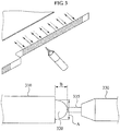
- FIG. 3 is a diagram illustrating discharge of a reflective material from a dispenser of an apparatus for preventing a light leakage from a light guide plate according to an exemplary embodiment.
- the apparatus for preventing a light leakage from a light guide plate may realize an optimum painting condition by measuring a distance between a light guide plate 310 and a dispenser 330, that is, a painting gap, and by maintaining the corresponding distance uniformly through interpolation.
- the painting condition may include a painting gap, a painting width A, and a painting height B.
- an exemplary embodiment may use a needle-type nozzle 335 to the dispenser 330, and may employ a mechanism of controlling the nozzle 335 to get closer to the reflective material 320 to a minimum painting gap and spreading the reflective material 320 by pressing down the reflective material 320 through direct contact.
- a discharge rate of the dispenser 330 may be controlled based on a processing error on at least one side surface of the light guide plate 310 or whether the light guide plate 310 is aligned with the dispenser 330, and accordingly, a reflective material layer of a uniform thickness may be formed on the at least one side surface of the light guide plate 310.
- the reflective material 320 may correspond to, for example, an acryl-based liquid-state reflective material or an epoxy-based liquid-state reflective material.
- the preventing apparatus may discharge the reflective material 320 to the light guide plate 310 through the nozzle 335 of the dispenser 330 based on the optimum painting condition.
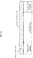
- the painting width A of the reflective material 320 discharged through the nozzle 335 of the dispenser 330 may correspond to 80% and 90% of a thickness of the light guide plate 310, and the painting height B may be in a range of 90 ⁇ m to 110 ⁇ m. That is, when the thickness of the light guide plate 310 is, for example, 2 millimeters (mm), the painting width of the reflective material 320 may range from 1.6 mm to 1.8 mm.
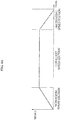
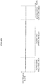
- FIGS. 4A through 4C are graphs illustrating a discharge rate of a dispenser and a painting width when control of the discharge rate of the dispenser by an apparatus for preventing a light leakage from a light guide plate according to an exemplary embodiment is undone.
- the graph of FIG. 4A illustrates a movement speed of a dispenser per unit time. As shown in the graph of FIG. 4B , a discharge rate of the dispenser per unit time may be uniform.
- the graph of FIG. 4C illustrates, in the above case, a correlation between the discharge rate of the dispenser and a width of the reflective material applied to the light guide plate when the discharge rate of the dispenser is uncontrolled.
- variable speed section may correspond to, for example, a section in which painting is conducted by the dispenser in motion or a section in which painting is executed while the light guide plate is in motion and the dispenser remains stationary. Accordingly, it may be impossible to maintain a uniform painting width throughout the entire side surface of the light guide plate as shown in FIG. 4C .
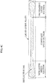
- FIGS. 5A through 5C are graphs illustrating a discharge rate of a dispenser and a painting width when the discharge rate of the dispenser is controlled by an apparatus for preventing a light leakage from a light guide plate according to an exemplary embodiment.
- the graph of FIG. 5A illustrates a movement speed of a dispenser per unit time. As shown in the graph of FIG. 5B , a discharge rate of the dispenser per unit time may be controlled.
- the graph of FIG. 5C illustrates a correlation between the discharge rate of the dispenser and a width of the reflective material applied to the light guide plate when the discharge rate of the dispenser per unit time is controlled by the preventing apparatus based on the movement speed of the dispenser.
- a greater amount of the reflective material may be used in painting o ver a variable speed section in which the movement speed of the dispenser increases or decreases than a constant speed section in which the movement speed of the dispenser is constant.
- the discharge rate of the dispenser may be controlled to discharge a relatively smaller amount of the reflective material across the variable speed section and a relative larger amount of the reflective material across the constant speed section.
- control unit of the preventing apparatus may control the discharge rate of the dispenser to allow the painting with the reflective material of a uniform width and a uniform height throughout the variable speed section and the constant speed section, as shown in FIG. 5C , by increasing the discharge rate of the dispenser with an increasing movement speed of the dispenser and by reducing the discharge rate of the dispenser with a decreasing movement speed of the dispenser.
- the discharge rate of the dispenser may be controlled based on a processing error on at least one side surface of the light guide plate or whether the light guide plate is aligned with the dispenser, and a reflective material layer of a uniform thickness may be formed on the at least one side surface of the light guide plate.
- the reflective material may correspond to, for example, an acryl-based liquid-state reflective material or an epoxy-based liquid-state reflective material.
- FIG. 6 is a diagram illustrating an apparatus for preventing a light leakage from a light guide plate viewed from the front and side according to another exemplary embodiment.
- the preventing apparatus may include a belt conveyor 610, a first moving stage 620, a pre-align unit 630, a second moving stage 640, a vision align unit 650, and a dispenser 660.
- the belt conveyor 610 may transfer a light guide plate 605 by a driving source carrying out synchronized control, for example, a servo motor.
- the belt conveyor 610 may consist of two conveyor belts, rather than a flat belt, to accommodate a stage unit used to move the light guide plate 605.
- the two conveyor belts may be controlled by each servo motor in a synchronized manner.
- the belt conveyor 610 may adjust a width between the two conveyor belts automatically through an LM guide, a ball screw, and a servo motor, to enable the transfer of light guide plates of various sizes.
- the first moving stage 620 may move vertically, and may move up the transferred light guide plate 605.
- the first moving stage 620 may further include a vacuum plate having a capacity to adsorb the light guide plate 605 to prevent misalignment during transferring the light guide plate 605.
- the first moving stage 620 may move the light guide plate 605 in an adsorbed state by the vacuum plate.
- the first moving stage 620 may enable the transfer of light guide plates of various sizes by replacing with a vacuum plate of a corresponding size by a light guide plate model change (M/C) among a plurality of vacuum plates of various suitable sizes prepared for each size group of the light guide plate.
- a driving source for the first moving stage 620 may be controlled by a servo motor.
- the pre-align unit 630 may align the light guide plate 605 seated on the first moving stage 620 to a first location.
- the second moving stage 640 may move along an X-axis and a Z-axis, that is, horizontally and vertically, and may move the light guide plate 605 aligned to the first location to a painting area. Similar to the first moving stage 620, the second moving stage 640 may enable the transfer of light guide plates of various sizes by replacing with a vacuum plate of a corresponding size by a light guide plate model change (M/C) among a plurality of vacuum plates of various suitable sizes prepared for each size group of the light guide plate.
- a driving source for the second moving stage 640 may be controlled by a servo motor.
- the vision align unit 650 may measure a processing error for each of at least one side surface of the light guide plate 605 and whether the light guide plate 605 is aligned with the dispenser 660, by conducting a line scan of the light guide plate 605 being transferred to the painting area.
- the vision align unit 650 may measure the processing error for each of the at least one side surface of the light guide plate 605 and whether the light guide plate 605 is aligned with the dispenser 660 by conducting a line scan using a vision camera moving horizontally based on a size of the light guide plate 605 transferred to the painting area.
- the vision align unit 650 may include a first vision align unit 653 and a second vision align unit 656, and the first vision align unit 653 and the second vision align unit 656 may correspond to, for example, a vision camera.
- the first vision align unit 653 may measure a processing error for each of a second surface and a third surface of the light guide plate 605 and whether the light guide plate 605 is aligned with the dispenser 660, by conducting a line scan of the second surface and the third surface of the light guide plate 605 being transferred to the painting area.
- the first vision align unit 653 may be fixed above the light guide plate 605, and may measure whether the light guide plate 605 is aligned with the dispenser 660 by conducting a line scan of the second surface and the third surface of the light guide plate 605 while the light guide plate 605 is being transferred by the second moving stage 640 to the painting area in an adsorbed state.
- a vision camera having a large field of view may be adopted, but it may cause increased costs.
- an exemplary embodiment may use a vision camera having a small field of view, and may measure whether a light guide plate is aligned properly using a vision camera moving along a Y-axis, that is, horizontally based on a size of the light guide plate.
- An operation of moving the vision camera may be controlled by a servo motor.
- the second vision align unit 656 may measure a processing error on a first surface of the light guide plate 605 and whether the light guide plate 605 is aligned with the dispenser 660 by conducting a line scan of the first surface of the light guide plate 605 transferred to the painting area.
- the dispenser 660 may paint at least one side surface of the light guide plate 605 with the reflective material under a preset painting condition, based on the processing error and whether the light guide plate 605 is aligned with the dispenser 660.
- the dispenser 660 may paint each side surface concurrently based on the size of the corresponding light guide plate 605 and the painting condition.
- the dispenser 660 may further include a robot 665 to perform vertical and horizontal interpolation based on the processing error for each of the at least one side surface of the light guide plate 605 and whether the light guide plate 605 is aligned with the dispenser 660.
- the robot 665 may perform X- and Y-axis interpolation based on a data value measured by the vision align unit 650, and may enable the painting while maintaining a predetermined distance between the light guide plate 605 and the dispenser 660, that is, a painting interval.
- the second moving stage 640 may move down to dispose the light guide plate 605 on the belt conveyor 670, and may move to an area of the first moving stage 640 where the second moving stage 640 may stand by for a next operation. Then, the belt conveyor 670 may transfer the light guide plate 605 to a hardener for a next process.
- the belt conveyor 670 may have the same configuration and function as the belt conveyor 610.
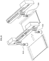
- FIG. 7 is a diagram illustrating a configuration of a dispenser and a vision align unit of an apparatus for preventing a light leakage from a light guide plate according to another exemplary embodiment.
- a vision align unit 730 may measure a processing error for each of at least one side surface of the light guide plate 700 and whether the light guide plate 700 is aligned with a dispenser 710.
- the dispenser 710 may paint the at least one side surface of the light guide plate 700 under controlled conditions based on data measured by the vision align unit 730, for example, an amount of a reflective material to be discharged through a nozzle 715, a painting interval, and a painting width.
- FIG. 8 is a diagram illustrating a configuration of a vision align unit of an apparatus for preventing a light leakage from a light guide plate according to another exemplary embodiment.
- a first vision align unit 810 and 820 may be fixed above a light guide plate, and the light guide plate may be moved to a painting area. Then, the fixed first vision align unit 810 and 820 may measure a processing error for each of at least one side surface of the light guide plate, for example, a second surface and a third surface and whether the light guide plate is aligned with the dispenser, by conducting a line scan of the second surface and the third surface of the light guide plate.
- a second vision align unit 830 may conduct a line scan of at least one remaining side surface of the light guide plate while moving directly above the light guide plate.
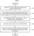
- FIG. 9 is a flowchart illustrating a method of preventing a light leakage from a light guide plate according to an exemplary embodiment.
- an apparatus for preventing a light leakage from a light guide plate hereinafter referred to as a preventing apparatus, may sense at least one side surface of the light guide plate.
- the preventing apparatus may measure a processing error present in the at least one side surface of the light guide plate or whether the light guide plate is aligned with a dispenser.
- the preventing apparatus may control a relative location of the dispenser to the light guide plate based on a result of the measurement in 920.
- the preventing apparatus may control a discharge rate of the dispenser, in turn, an amount of a reflective material to be discharged from the dispenser to the at least one side surface of the light guide plate.
- the preventing apparatus may discharge the reflective material from the dispenser to the at least one side surface of the light guide plate.
- the preventing apparatus may control the discharge rate of the dispenser based on a movement speed of the dispenser, to form a reflective material layer of a uniform thickness on the at least one side surface of the light guide plate.
- the preventing apparatus may control the discharge rate of the dispenser, that is, the amount of the reflective material for the at least one side surface of the light guide plate, based on the processing error.
- the preventing apparatus may control the relative location of the dispenser to the light guide plate based on the processing error or whether the light guide plate is aligned with the dispenser.
- the preventing apparatus may, in operation 940, control the discharge rate of the dispenser based on the movement speed of the dispenser.
- the preventing apparatus may change the discharge rate of the dispenser linearly with a change in the movement speed of the dispenser. More particularly, the preventing apparatus may increase the discharge rate of the dispenser with an increasing movement speed of the dispenser, and may reduce the discharge rate of the dispenser with a decreasing movement speed of the dispenser.
- the preventing apparatus may allow the painting with the reflective material of a uniform painting width and a uniform painting height over the entire painting area.
- the preventing apparatus may change the discharge rate of the dispenser with the change in the movement speed of the dispenser, for example, by exponential, logarithmic and differential relationships and a multi-dimensional function relationship.
- the preventing apparatus may support the light guide plate to enable the dispenser to discharge the reflective material in such a state that the dispenser is in a horizontal relationship with the light guide plate.
- the light guide plate is perpendicular to the ground, more space may be needed to manufacture an equipment and complexity in equipment configuration may increase.
- an exemplary embodiment may support the dispenser and the light guide plate on a horizontal level to enable discharging and painting of the reflective material in such a state that the dispenser is in a horizontal relationship with the light guide plate.
- the preventing apparatus may paint the at least one side surface of the light guide plate with the reflective material based on the discharge rate of the dispenser.
- FIG. 10 is a flowchart illustrating a method of preventing a light leakage from a light guide plate according to another exemplary embodiment.
- an apparatus for preventing a light leakage from a light guide plate may transfer a light guide plate to a location of a first moving stage through a belt conveyor when the light guide plate is put in.
- the preventing apparatus may determine whether the light guide plate is disposed at the location of the first moving stage using a sensor.
- the preventing apparatus may pre-align the light guide plate to a first location by moving up the light guide plate transferred to the first moving stage by the belt conveyor.
- the preventing apparatus may align the light guide plate to the first location by moving up the light guide plate disposed on the first moving stage in an absorbed state based on a result of the measurement in operation 1010.
- the preventing apparatus may adsorb to transfer the light guide plate aligned to the first location to a painting area.
- a second moving stage may move up and may adsorb the light guide plate disposed on the first moving stage by vacuum whereas the first moving stage may release the vacuum and may move down.
- the preventing apparatus may conduct a line scan for each of at least one side surface of the light guide plate using a plurality of vision cameras.
- the preventing apparatus may, in operation 1040, conduct a line scan by a vision camera moving horizontally based on a size of the light guide plate transferred to the painting area.
- the preventing apparatus may conduct a line scan of at least one side surface of the light guide plate, for example, a second surface and a third surface, using at least two first vision cameras fixed above the light guide plate. Subsequently, when transfer to the painting area is completed, the preventing apparatus may conduct a line scan of a remaining side surface of the light guide plate, for example, a first surface, using a second vision camera.
- the preventing apparatus may measure a processing error for each of the at least one side surface of the light guide plate and whether the light guide plate is aligned with the dispenser, based on a result of the scan.
- whether the light guide plate is aligned with the dispenser may represent how much a location of the light guide plate is misaligned with a location of the dispenser.
- the preventing apparatus may perform interpolation for the location of the light guide plate based on the processing error for each of the at least one side surface of the light guide plate and whether the light guide plate is aligned with the dispenser.
- the preventing apparatus may uniformly maintain a distance between the light guide plate and a tip of a nozzle of the dispenser, that is, a painting interval by controlling a robot of the dispenser using the processing error for each of the at least one side surface of the light guide plate and a measurement value for misalignment of the light guide plate from the dispenser.
- the preventing apparatus may paint the at least one side surface of the light guide plate with the reflective material under a preset painting condition with respect to the interpolated location based on the processing error or whether the light guide plate is aligned with the dispenser.
- the preventing apparatus may paint the at least one side surface of the light guide plate with the reflective material while maintaining a predetermined distance from the light guide plate with respect to the interpolated location.
- the preventing apparatus may release the vacuum applied by the second moving stage and may put down the light guide plate on the belt conveyor. Then, the belt conveyor may transfer the light guide plate to a drying furnace for a next process, during which the second moving stage may move to a location of the first moving stage to adsorb a new light guide plate.
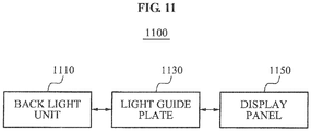
- FIG. 11 is a block diagram illustrating a display device having a light guide plate painted with a reflective material according to an exemplary embodiment.
- the display device 1100 may include a back light unit 1110, a light guide plate 1130, and a display panel 1150.
- the back light unit 1110 may generate light.
- the light guide plate 1130 may have at least one side surface, and to prevent the light generated from the back light unit 1110 from leaking from the light guide plate 1130, the at least one side surface of the light guide plate 1130 may be painted with a reflective material.
- the at least one side surface of the light guide plate 1130 may be painted with a controlled amount of the reflective material discharged based on a processing error for the at least one side surface of the light guide plate 1130 or whether the light guide plate 1130 is aligned properly.
- a width of the reflective material discharged to the at least one side surface of the light guide plate 1130 may correspond to 80% to 90% of a thickness of the light guide plate 1130.
- the reflective material may correspond to, for example, acryl-based liquid-state reflective material or an epoxy-based liquid-state reflective material.
- the display panel 1150 may be disposed on the light guide plate 1130.
- the above-described exemplary embodiments of the present invention may be recorded in computer-readable media including program instructions to implement various operations embodied by a computer.
- the media may also include, alone or in combination with the program instructions, data files, data structures, and the like.
- Examples of computer-readable media include magnetic media such as hard discs, floppy discs, and magnetic tape; optical media such as CD ROM discs and DVDs; magneto-optical media such as floptical discs; and hardware devices that are specially configured to store and perform program instructions, such as read-only memory (ROM), random access memory (RAM), flash memory, and the like.
- Examples of program instructions include both machine code, such as produced by a compiler, and files containing higher level code that may be executed by the computer using an interpreter.
- the described hardware devices may be configured to act as one or more software modules in order to perform the operations of the above-described exemplary embodiments of the present invention, or vice versa.
- a reflective ink of a lower price than a reflective tape may be used in preventing light emitted from a cold cathode fluorescent lamp (CCFL) or a light emitting diode (LED) from leaking from a side surface of a light guide plate, to reduce production costs.
- CCFL cold cathode fluorescent lamp
- LED light emitting diode
- a side surface of a light guide plate may be painted with a reflective material discharged from a dispenser in such a state that the dispenser is in a horizontal relationship with the light guide plate with respect to the ground, to optimize an equipment configuration and an installation space and to minimize equipment investment costs, compared to a case in which the dispenser is in a vertical relationship with the light guide plate.
- an optimum painting condition for example, a painting width and a painting height, may be realized by measuring a distance between a light guide plate and a dispenser using a vision camera and by maintaining the corresponding distance uniformly by interpolation, to improve a product quality.
- a discharge rate of a dispenser may be controlled in real time based on a movement speed of the dispenser to paint a light guide plate with a reflective material with the same painting width and height throughout a constant speed section and a variable speed section in which the movement speed of the dispenser increases or decreases per unit time, resulting in improved product quality.
Landscapes
- Physics & Mathematics (AREA)
- General Physics & Mathematics (AREA)
- Optics & Photonics (AREA)
- Engineering & Computer Science (AREA)
- Theoretical Computer Science (AREA)
- Mathematical Physics (AREA)
- Manufacturing & Machinery (AREA)
- Nonlinear Science (AREA)
- Software Systems (AREA)
- General Engineering & Computer Science (AREA)
- Databases & Information Systems (AREA)
- Data Mining & Analysis (AREA)
- Chemical & Material Sciences (AREA)
- Crystallography & Structural Chemistry (AREA)
- Planar Illumination Modules (AREA)
- Liquid Crystal (AREA)
- Application Of Or Painting With Fluid Materials (AREA)
Claims (11)
- Vorrichtung zur Verhinderung von Lichtverlust aus einer Lichtleiterplatte (310; 605; 700; 1130), die Vorrichtung (200) dadurch gekennzeichnet, dass sie Folgendes umfasst:eine Abtasteinheit (210) zum Abtasten von mindestens einer Seitenoberfläche einer Lichtleiterplatte;einen Geber (220; 330; 710) zum Abgeben eines reflektierenden flüssigen Materials (320) an die mindestens eine Seitenoberfläche der Lichtleiterplatte, um zu verhindern, dass Licht, erzeugt von einer Rücklichteinheit (1110) aus der Seitenoberfläche der Lichtleiterplatte austritt;eine Messeinheit (240) zum Messen eines Verarbeitungsfehlers, vorhanden in der mindestens einen Seitenoberfläche der Lichtleiterplatte, oder ob die Lichtleiterplatte auf den Geber ausgerichtet ist;undeine Steuerungseinheit (230) zum Steuern des Gebers auf der Basis der Messung, die Steuerung umfassend das Steuern einer Menge des reflektierenden flüssigen Materials, abzugeben an die mindestens eine Seitenoberfläche der Lichtleiterplatte, oder Steuern des relativen Standorts des Gebers zu der Lichtleiterplatte.
- Vorrichtung nach Anspruch 1, wobei der Geber (220; 330; 710) angeordnet ist zum Abgeben des reflektierenden flüssigen Materials (320) während des Bewegens entlang der mindestens einen Seitenoberfläche der Lichtleiterplatte (310; 605; 700; 1130) in einer Längsrichtung in einem gleichmäßigen Abstand von der Lichtleiterplatte.
- Vorrichtung nach Anspruch 1 oder 2, wobei der Geber (220; 330; 710) angeordnet ist zum Abgeben des reflektierenden flüssigen Materials (320) an die mindestens eine Seitenoberfläche der Lichtleiterplatte (310; 605; 700; 1130) mit einer Breite (A) entsprechend 80 % bis 90 % einer Dicke der Lichtleiterplatte.
- Vorrichtung nach Anspruch 1, wobei der Geber (220; 330; 710) angeordnet ist zum Abgeben des reflektierenden flüssigen Materials (320) an die mindestens eine Seitenoberfläche der Lichtleiterplatte (310; 605; 700; 1130) mit einer Lagendicke (B) des abgegebenen reflektierenden flüssigen Materials in einem Bereich von 90 Mikrometern (µm) bis 110 µm.
- Vorrichtung nach Anspruch 1, wobei der Geber (220; 330; 710) angeordnet ist zum Abgeben des reflektierenden flüssigen Materials (320) in einem Winkelbereich von -45 Grad bis +45 Grad relativ zu der Lichtleiterplatte (310; 605; 700; 1130) in Bezug auf die Horizontale.
- Vorrichtung nach Anspruch 1, wobei die Steuerungseinheit angeordnet ist zum Steuern der Abgaberate des Gebers (220; 330; 710) auf der Basis der Bewegungsgeschwindigkeit des Gebers, um eine reflektierende Materiallage von einer gleichmäßigen Dicke (B) auf der mindestens einen Seitenoberfläche der Lichtleiterplatte (310; 605;700; 1130) zu bilden.
- Vorrichtung nach Anspruch 6, wobei die Steuerungseinheit (230) angeordnet ist zum Erhöhen der Abgaberate des Gebers (220; 330; 710) mit zunehmender Bewegungsgeschwindigkeit des Gebers und angeordnet ist zum Vermindern der Abgaberate des Gebers mit abnehmender Bewegungsgeschwindigkeit des Gebers.
- Verfahren zum Verhindern von Lichtverlust aus einer Lichtleiterplatte (310; 605; 700; 1130), das Verfahren dadurch gekennzeichnet, dass es folgende automatisch ausgeführte Schritte umfasst:Abtasten an mindestens einer Seitenoberfläche einer Lichtleiterplatte (310; 605; 700; 1130);Messen eines Verarbeitungsfehlers in der mindestens einen Seitenoberfläche der Lichtleiterplatte oder ob die Lichtleiterplatte auf einen Geber (220; 330; 710) ausgerichtet ist; undAbgeben eines reflektierenden flüssigen Materials (320) von dem Geber an die mindestens eine Seitenoberfläche der Lichtleiterplatte;wobei, während des Abgebens und auf der Basis der Messung, einer Menge des reflektierenden flüssigen Materials, abzugeben an die mindestens eine Seitenoberfläche der Lichtleiterplatte gesteuert wird oder der relative Standort des Gebers zu der Lichtleiterplatte gesteuert wird.
- Lichtleiterplatte, dadurch gekennzeichnet, dass sie mindestens eine Seitenoberfläche aufweist, die automatisch durch ein Verfahren nach Anspruch 8 mit einem abgegebenen flüssigen Material (320) angemalt ist, um zu verhindern, dass Licht, erzeugt von einer Rücklichteinheit (1110) aus der Lichtleiterplatte (310; 605; 700; 1130) austritt.
- Lichtleiterplatte nach Anspruch 9, wobei eine Breite (A) des reflektierenden flüssigen Materials (320), abgegeben an die mindestens eine Seitenoberfläche der Lichtleiterplatte (310; 605; 700; 1130), 80 % bis 90 % einer Dicke der Lichtleiterplatte entspricht.
- Lichtleiterplatte nach Anspruch 9 oder Anspruch 10, wobei die Lichtleiterplatte (310; 605; 700; 1130) Teil einer Anzeigevorrichtung (1100) ist, welche Anzeigevorrichtung ferner eine Rücklichteinheit (1110) zum Erzeugen von Licht und eine auf der Lichtleiterplatte angeordnete Anzeigetafel (1150) umfasst.
Priority Applications (1)
| Application Number | Priority Date | Filing Date | Title |
|---|---|---|---|
| PL13165436T PL2657594T3 (pl) | 2012-04-25 | 2013-04-25 | Sposób i urządzenie do zapobiegania przedostawaniu się światła z płyty kierującej światło i urządzenie wyświetlające mające płytę kierującą światło pomalowaną materiałem odblaskowym |
Applications Claiming Priority (1)
| Application Number | Priority Date | Filing Date | Title |
|---|---|---|---|
| KR1020120043220A KR101304715B1 (ko) | 2012-04-25 | 2012-04-25 | 도광판에서의 빛 누출 방지 방법 및 그 장치와 반사재가 토출된 도광판을 가지는 디스플레이 장치 |
Publications (2)
| Publication Number | Publication Date |
|---|---|
| EP2657594A1 EP2657594A1 (de) | 2013-10-30 |
| EP2657594B1 true EP2657594B1 (de) | 2019-03-13 |
Family
ID=48468131
Family Applications (1)
| Application Number | Title | Priority Date | Filing Date |
|---|---|---|---|
| EP13165436.0A Active EP2657594B1 (de) | 2012-04-25 | 2013-04-25 | Verfahren und Vorrichtung zur Verhinderung von Lichtverlusten aus Lichtleiterplatten und Anzeigevorrichtung mit einer mit reflektierendem Material lackierten Lichtleiterplatte |
Country Status (9)
| Country | Link |
|---|---|
| US (1) | US20130289764A1 (de) |
| EP (1) | EP2657594B1 (de) |
| JP (1) | JP5745569B2 (de) |
| KR (1) | KR101304715B1 (de) |
| CN (1) | CN103424927A (de) |
| BR (1) | BR102013010062B1 (de) |
| MX (1) | MX2013004672A (de) |
| PL (1) | PL2657594T3 (de) |
| TW (1) | TWI509299B (de) |
Families Citing this family (3)
| Publication number | Priority date | Publication date | Assignee | Title |
|---|---|---|---|---|
| JP6525535B2 (ja) * | 2014-09-09 | 2019-06-05 | 三菱電機株式会社 | 光源ユニット、照明ランプ及び照明装置 |
| WO2016060052A1 (ja) * | 2014-10-15 | 2016-04-21 | シャープ株式会社 | 照明装置、表示装置、及び照明装置の製造方法 |
| JP6787547B2 (ja) * | 2016-01-22 | 2020-11-18 | ショーダテクトロン株式会社 | 端面塗布装置 |
Family Cites Families (23)
| Publication number | Priority date | Publication date | Assignee | Title |
|---|---|---|---|---|
| JPH04271866A (ja) * | 1991-02-27 | 1992-09-28 | Hitachi Medical Corp | 真空管用固体潤滑転動玉軸受の潤滑剤塗布方法及び塗布装置 |
| US5741558A (en) * | 1993-04-07 | 1998-04-21 | Nordson Corporation | Method and apparatus for coating three dimensional articles |
| US5736686A (en) * | 1995-03-01 | 1998-04-07 | Gtco Corporation | Illumination apparatus for a digitizer tablet with improved light panel |
| EP0879991A3 (de) * | 1997-05-13 | 1999-04-21 | Matsushita Electric Industrial Co., Ltd. | Beleuchtungssystème |
| JPH11353922A (ja) * | 1998-06-10 | 1999-12-24 | Advanced Display Inc | 照明装置およびこれを備えた液晶表示装置並びに照明装置の製造方法 |
| JP2001166298A (ja) * | 1999-12-03 | 2001-06-22 | Mitsubishi Electric Corp | 液晶表示装置用バックライトおよび液晶表示装置用バックライトの製造方法 |
| JP2002268061A (ja) * | 2001-03-09 | 2002-09-18 | Nitto Denko Corp | 反射型液晶表示装置 |
| DE10222250A1 (de) * | 2002-05-16 | 2003-11-27 | Roehm Gmbh | Verbesserte Lichtleitkörper sowie Verfahren zu dessen Herstellung |
| US20070248307A1 (en) * | 2002-10-04 | 2007-10-25 | Page David J | Transparent light emitting members and method of manufacture |
| TWI282015B (en) * | 2003-08-22 | 2007-06-01 | Hon Hai Prec Ind Co Ltd | Process about a reflective film of a light guide plate |
| KR100665936B1 (ko) * | 2004-04-21 | 2007-01-09 | 주식회사 나래나노텍 | 박막 성형공정에서 코팅막 두께 검출장치 및 방법 |
| KR100677122B1 (ko) * | 2004-06-23 | 2007-02-02 | 삼성전자주식회사 | 백라이트 유닛용 도광판 및 그 제조방법 |
| CN100555043C (zh) * | 2006-08-29 | 2009-10-28 | 瀚宇彩晶股份有限公司 | 显示器的背光模块及其检测方法 |
| EP2095159A1 (de) * | 2006-12-18 | 2009-09-02 | E. I. Du Pont de Nemours and Company | Diffuser reflektor mit einem vlies-blatt mit spezifischem reflexionsgrad und dickeabweichungen zur verwendung in displays |
| JP5457176B2 (ja) * | 2007-06-08 | 2014-04-02 | 東洋鋼鈑株式会社 | 光反射板の製造方法 |
| KR101273083B1 (ko) * | 2007-06-21 | 2013-06-10 | 엘지이노텍 주식회사 | 발광장치 |
| JP2009128647A (ja) * | 2007-11-26 | 2009-06-11 | Hitachi Displays Ltd | 液晶表示装置 |
| US7980748B2 (en) * | 2008-08-28 | 2011-07-19 | Sharp Kabushiki Kaisha | Lighting system including light guide with reflective micro structures on edge surfaces |
| JP2010125422A (ja) * | 2008-11-28 | 2010-06-10 | Nissan Motor Co Ltd | 塗工装置および塗工装置の制御方法 |
| JP4877372B2 (ja) * | 2009-08-28 | 2012-02-15 | カシオ計算機株式会社 | 塗布装置及び塗布方法 |
| JP2012015324A (ja) * | 2010-06-30 | 2012-01-19 | Fujifilm Corp | 液体塗布装置及び液体塗布方法並びにナノインプリントシステム |
| EP2500623A1 (de) * | 2011-03-18 | 2012-09-19 | Koninklijke Philips Electronics N.V. | Verfahren zur Bereitstellung einer reflektierenden Beschichtung auf einem Substrat für eine lichtemittierende Vorrichtung |
| US20130063965A1 (en) * | 2011-09-14 | 2013-03-14 | Shenzhen China Star Optoelectronics Technology Co.,Ltd. | Light guide plate and backlight module |
-
2012
- 2012-04-25 KR KR1020120043220A patent/KR101304715B1/ko active Active
-
2013
- 2013-04-24 TW TW102114651A patent/TWI509299B/zh active
- 2013-04-25 US US13/870,683 patent/US20130289764A1/en not_active Abandoned
- 2013-04-25 MX MX2013004672A patent/MX2013004672A/es active IP Right Grant
- 2013-04-25 BR BR102013010062-5A patent/BR102013010062B1/pt active IP Right Grant
- 2013-04-25 PL PL13165436T patent/PL2657594T3/pl unknown
- 2013-04-25 CN CN2013101479381A patent/CN103424927A/zh active Pending
- 2013-04-25 EP EP13165436.0A patent/EP2657594B1/de active Active
- 2013-04-25 JP JP2013092013A patent/JP5745569B2/ja active Active
Non-Patent Citations (1)
| Title |
|---|
| None * |
Also Published As
| Publication number | Publication date |
|---|---|
| MX2013004672A (es) | 2014-02-06 |
| BR102013010062B1 (pt) | 2020-11-24 |
| JP2013229332A (ja) | 2013-11-07 |
| KR101304715B1 (ko) | 2013-09-06 |
| BR102013010062A2 (pt) | 2015-06-16 |
| PL2657594T3 (pl) | 2019-08-30 |
| TW201350943A (zh) | 2013-12-16 |
| CN103424927A (zh) | 2013-12-04 |
| US20130289764A1 (en) | 2013-10-31 |
| EP2657594A1 (de) | 2013-10-30 |
| JP5745569B2 (ja) | 2015-07-08 |
| TWI509299B (zh) | 2015-11-21 |
Similar Documents
| Publication | Publication Date | Title |
|---|---|---|
| KR101129193B1 (ko) | 페이스트 디스펜서의 제어방법 | |
| CN101444773B (zh) | 检测涂胶机的喷孔和激光位移传感器的光点的位置的位置检测设备和方法 | |
| KR101911701B1 (ko) | 페이스트 디스펜서 및 그 제어방법 | |
| EP2538267B1 (de) | Betitelungsverfahren und -vorrichtung | |
| EP2657594A1 (de) | Verfahren und Vorrichtung zur Verhinderung von Lichtverlusten aus Lichtleiterplatten und Anzeigevorrichtung mit einer mit reflektierendem Material lackierten Lichtleiterplatte | |
| KR101578859B1 (ko) | 터치 스크린 디스플레이 조립체의 접합 장치 | |
| CN102085510A (zh) | 用于控制涂胶机的方法 | |
| KR101392837B1 (ko) | 형상 추적 기능을 가지는 접착제 도포장치 | |
| CN101178520A (zh) | 糊状物分配装置 | |
| CN102023416A (zh) | 密封胶涂布机和密封胶涂布方法 | |
| TWI611845B (zh) | 膠塗佈機 | |
| CN108393212B (zh) | 分配装置 | |
| CN102085505A (zh) | 控制密封胶涂布机的方法 | |
| KR20110028778A (ko) | 페이스트 도포방법 | |
| US20110236578A1 (en) | Paste applicator and paste applying method | |
| KR20120115801A (ko) | 디스플레이 패널 검사장치 | |
| KR20070088345A (ko) | 실런트 도포 상태에 근거한 액정 적하량 결정 방법 | |
| US20140090529A1 (en) | Dust Protection Method for Glass Substrate Cutter | |
| CN101676774A (zh) | 一种用于显示密封胶图案的待查区域的方法 | |
| JP4532512B2 (ja) | シーラント塗布状態に基づいた液晶滴下量決定方法 | |
| KR101107499B1 (ko) | 페이스트 디스펜서 및 그 제어방법 | |
| KR101841219B1 (ko) | 페이스트 디스펜서 | |
| KR101347162B1 (ko) | 액정패널용 광학특성 측정장비 | |
| KR20120077294A (ko) | 페이스트 디스펜서 | |
| KR101186832B1 (ko) | 필름 연결부 컷팅장치 |
Legal Events
| Date | Code | Title | Description |
|---|---|---|---|
| PUAI | Public reference made under article 153(3) epc to a published international application that has entered the european phase |
Free format text: ORIGINAL CODE: 0009012 |
|
| AK | Designated contracting states |
Kind code of ref document: A1 Designated state(s): AL AT BE BG CH CY CZ DE DK EE ES FI FR GB GR HR HU IE IS IT LI LT LU LV MC MK MT NL NO PL PT RO RS SE SI SK SM TR |
|
| AX | Request for extension of the european patent |
Extension state: BA ME |
|
| 17P | Request for examination filed |
Effective date: 20140429 |
|
| RBV | Designated contracting states (corrected) |
Designated state(s): AL AT BE BG CH CY CZ DE DK EE ES FI FR GB GR HR HU IE IS IT LI LT LU LV MC MK MT NL NO PL PT RO RS SE SI SK SM TR |
|
| GRAP | Despatch of communication of intention to grant a patent |
Free format text: ORIGINAL CODE: EPIDOSNIGR1 |
|
| STAA | Information on the status of an ep patent application or granted ep patent |
Free format text: STATUS: GRANT OF PATENT IS INTENDED |
|
| INTG | Intention to grant announced |
Effective date: 20180726 |
|
| GRAJ | Information related to disapproval of communication of intention to grant by the applicant or resumption of examination proceedings by the epo deleted |
Free format text: ORIGINAL CODE: EPIDOSDIGR1 |
|
| STAA | Information on the status of an ep patent application or granted ep patent |
Free format text: STATUS: REQUEST FOR EXAMINATION WAS MADE |
|
| INTC | Intention to grant announced (deleted) | ||
| GRAR | Information related to intention to grant a patent recorded |
Free format text: ORIGINAL CODE: EPIDOSNIGR71 |
|
| GRAS | Grant fee paid |
Free format text: ORIGINAL CODE: EPIDOSNIGR3 |
|
| STAA | Information on the status of an ep patent application or granted ep patent |
Free format text: STATUS: GRANT OF PATENT IS INTENDED |
|
| GRAA | (expected) grant |
Free format text: ORIGINAL CODE: 0009210 |
|
| STAA | Information on the status of an ep patent application or granted ep patent |
Free format text: STATUS: THE PATENT HAS BEEN GRANTED |
|
| INTG | Intention to grant announced |
Effective date: 20190130 |
|
| AK | Designated contracting states |
Kind code of ref document: B1 Designated state(s): AL AT BE BG CH CY CZ DE DK EE ES FI FR GB GR HR HU IE IS IT LI LT LU LV MC MK MT NL NO PL PT RO RS SE SI SK SM TR |
|
| REG | Reference to a national code |
Ref country code: GB Ref legal event code: FG4D |
|
| REG | Reference to a national code |
Ref country code: CH Ref legal event code: EP Ref country code: AT Ref legal event code: REF Ref document number: 1108201 Country of ref document: AT Kind code of ref document: T Effective date: 20190315 |
|
| REG | Reference to a national code |
Ref country code: IE Ref legal event code: FG4D |
|
| REG | Reference to a national code |
Ref country code: DE Ref legal event code: R096 Ref document number: 602013052152 Country of ref document: DE |
|
| REG | Reference to a national code |
Ref country code: NL Ref legal event code: MP Effective date: 20190313 |
|
| REG | Reference to a national code |
Ref country code: LT Ref legal event code: MG4D |
|
| PG25 | Lapsed in a contracting state [announced via postgrant information from national office to epo] |
Ref country code: NO Free format text: LAPSE BECAUSE OF FAILURE TO SUBMIT A TRANSLATION OF THE DESCRIPTION OR TO PAY THE FEE WITHIN THE PRESCRIBED TIME-LIMIT Effective date: 20190613 Ref country code: LT Free format text: LAPSE BECAUSE OF FAILURE TO SUBMIT A TRANSLATION OF THE DESCRIPTION OR TO PAY THE FEE WITHIN THE PRESCRIBED TIME-LIMIT Effective date: 20190313 Ref country code: FI Free format text: LAPSE BECAUSE OF FAILURE TO SUBMIT A TRANSLATION OF THE DESCRIPTION OR TO PAY THE FEE WITHIN THE PRESCRIBED TIME-LIMIT Effective date: 20190313 Ref country code: SE Free format text: LAPSE BECAUSE OF FAILURE TO SUBMIT A TRANSLATION OF THE DESCRIPTION OR TO PAY THE FEE WITHIN THE PRESCRIBED TIME-LIMIT Effective date: 20190313 |
|
| PG25 | Lapsed in a contracting state [announced via postgrant information from national office to epo] |
Ref country code: RS Free format text: LAPSE BECAUSE OF FAILURE TO SUBMIT A TRANSLATION OF THE DESCRIPTION OR TO PAY THE FEE WITHIN THE PRESCRIBED TIME-LIMIT Effective date: 20190313 Ref country code: NL Free format text: LAPSE BECAUSE OF FAILURE TO SUBMIT A TRANSLATION OF THE DESCRIPTION OR TO PAY THE FEE WITHIN THE PRESCRIBED TIME-LIMIT Effective date: 20190313 Ref country code: BG Free format text: LAPSE BECAUSE OF FAILURE TO SUBMIT A TRANSLATION OF THE DESCRIPTION OR TO PAY THE FEE WITHIN THE PRESCRIBED TIME-LIMIT Effective date: 20190613 Ref country code: HR Free format text: LAPSE BECAUSE OF FAILURE TO SUBMIT A TRANSLATION OF THE DESCRIPTION OR TO PAY THE FEE WITHIN THE PRESCRIBED TIME-LIMIT Effective date: 20190313 Ref country code: LV Free format text: LAPSE BECAUSE OF FAILURE TO SUBMIT A TRANSLATION OF THE DESCRIPTION OR TO PAY THE FEE WITHIN THE PRESCRIBED TIME-LIMIT Effective date: 20190313 Ref country code: GR Free format text: LAPSE BECAUSE OF FAILURE TO SUBMIT A TRANSLATION OF THE DESCRIPTION OR TO PAY THE FEE WITHIN THE PRESCRIBED TIME-LIMIT Effective date: 20190614 |
|
| REG | Reference to a national code |
Ref country code: AT Ref legal event code: MK05 Ref document number: 1108201 Country of ref document: AT Kind code of ref document: T Effective date: 20190313 |
|
| PG25 | Lapsed in a contracting state [announced via postgrant information from national office to epo] |
Ref country code: PT Free format text: LAPSE BECAUSE OF FAILURE TO SUBMIT A TRANSLATION OF THE DESCRIPTION OR TO PAY THE FEE WITHIN THE PRESCRIBED TIME-LIMIT Effective date: 20190713 Ref country code: EE Free format text: LAPSE BECAUSE OF FAILURE TO SUBMIT A TRANSLATION OF THE DESCRIPTION OR TO PAY THE FEE WITHIN THE PRESCRIBED TIME-LIMIT Effective date: 20190313 Ref country code: AL Free format text: LAPSE BECAUSE OF FAILURE TO SUBMIT A TRANSLATION OF THE DESCRIPTION OR TO PAY THE FEE WITHIN THE PRESCRIBED TIME-LIMIT Effective date: 20190313 Ref country code: IT Free format text: LAPSE BECAUSE OF FAILURE TO SUBMIT A TRANSLATION OF THE DESCRIPTION OR TO PAY THE FEE WITHIN THE PRESCRIBED TIME-LIMIT Effective date: 20190313 Ref country code: RO Free format text: LAPSE BECAUSE OF FAILURE TO SUBMIT A TRANSLATION OF THE DESCRIPTION OR TO PAY THE FEE WITHIN THE PRESCRIBED TIME-LIMIT Effective date: 20190313 Ref country code: SK Free format text: LAPSE BECAUSE OF FAILURE TO SUBMIT A TRANSLATION OF THE DESCRIPTION OR TO PAY THE FEE WITHIN THE PRESCRIBED TIME-LIMIT Effective date: 20190313 Ref country code: ES Free format text: LAPSE BECAUSE OF FAILURE TO SUBMIT A TRANSLATION OF THE DESCRIPTION OR TO PAY THE FEE WITHIN THE PRESCRIBED TIME-LIMIT Effective date: 20190313 Ref country code: CZ Free format text: LAPSE BECAUSE OF FAILURE TO SUBMIT A TRANSLATION OF THE DESCRIPTION OR TO PAY THE FEE WITHIN THE PRESCRIBED TIME-LIMIT Effective date: 20190313 |
|
| PG25 | Lapsed in a contracting state [announced via postgrant information from national office to epo] |
Ref country code: SM Free format text: LAPSE BECAUSE OF FAILURE TO SUBMIT A TRANSLATION OF THE DESCRIPTION OR TO PAY THE FEE WITHIN THE PRESCRIBED TIME-LIMIT Effective date: 20190313 |
|
| REG | Reference to a national code |
Ref country code: CH Ref legal event code: PL |
|
| REG | Reference to a national code |
Ref country code: DE Ref legal event code: R097 Ref document number: 602013052152 Country of ref document: DE |
|
| REG | Reference to a national code |
Ref country code: BE Ref legal event code: MM Effective date: 20190430 |
|
| PG25 | Lapsed in a contracting state [announced via postgrant information from national office to epo] |
Ref country code: IS Free format text: LAPSE BECAUSE OF FAILURE TO SUBMIT A TRANSLATION OF THE DESCRIPTION OR TO PAY THE FEE WITHIN THE PRESCRIBED TIME-LIMIT Effective date: 20190713 Ref country code: AT Free format text: LAPSE BECAUSE OF FAILURE TO SUBMIT A TRANSLATION OF THE DESCRIPTION OR TO PAY THE FEE WITHIN THE PRESCRIBED TIME-LIMIT Effective date: 20190313 Ref country code: LU Free format text: LAPSE BECAUSE OF NON-PAYMENT OF DUE FEES Effective date: 20190425 |
|
| PLBE | No opposition filed within time limit |
Free format text: ORIGINAL CODE: 0009261 |
|
| STAA | Information on the status of an ep patent application or granted ep patent |
Free format text: STATUS: NO OPPOSITION FILED WITHIN TIME LIMIT |
|
| PG25 | Lapsed in a contracting state [announced via postgrant information from national office to epo] |
Ref country code: DK Free format text: LAPSE BECAUSE OF FAILURE TO SUBMIT A TRANSLATION OF THE DESCRIPTION OR TO PAY THE FEE WITHIN THE PRESCRIBED TIME-LIMIT Effective date: 20190313 Ref country code: CH Free format text: LAPSE BECAUSE OF NON-PAYMENT OF DUE FEES Effective date: 20190430 Ref country code: MC Free format text: LAPSE BECAUSE OF FAILURE TO SUBMIT A TRANSLATION OF THE DESCRIPTION OR TO PAY THE FEE WITHIN THE PRESCRIBED TIME-LIMIT Effective date: 20190313 Ref country code: LI Free format text: LAPSE BECAUSE OF NON-PAYMENT OF DUE FEES Effective date: 20190430 |
|
| 26N | No opposition filed |
Effective date: 20191216 |
|
| PG25 | Lapsed in a contracting state [announced via postgrant information from national office to epo] |
Ref country code: BE Free format text: LAPSE BECAUSE OF NON-PAYMENT OF DUE FEES Effective date: 20190430 Ref country code: SI Free format text: LAPSE BECAUSE OF FAILURE TO SUBMIT A TRANSLATION OF THE DESCRIPTION OR TO PAY THE FEE WITHIN THE PRESCRIBED TIME-LIMIT Effective date: 20190313 |
|
| PG25 | Lapsed in a contracting state [announced via postgrant information from national office to epo] |
Ref country code: TR Free format text: LAPSE BECAUSE OF FAILURE TO SUBMIT A TRANSLATION OF THE DESCRIPTION OR TO PAY THE FEE WITHIN THE PRESCRIBED TIME-LIMIT Effective date: 20190313 |
|
| PG25 | Lapsed in a contracting state [announced via postgrant information from national office to epo] |
Ref country code: IE Free format text: LAPSE BECAUSE OF NON-PAYMENT OF DUE FEES Effective date: 20190425 |
|
| PG25 | Lapsed in a contracting state [announced via postgrant information from national office to epo] |
Ref country code: FR Free format text: LAPSE BECAUSE OF NON-PAYMENT OF DUE FEES Effective date: 20190513 |
|
| PG25 | Lapsed in a contracting state [announced via postgrant information from national office to epo] |
Ref country code: CY Free format text: LAPSE BECAUSE OF FAILURE TO SUBMIT A TRANSLATION OF THE DESCRIPTION OR TO PAY THE FEE WITHIN THE PRESCRIBED TIME-LIMIT Effective date: 20190313 |
|
| PG25 | Lapsed in a contracting state [announced via postgrant information from national office to epo] |
Ref country code: HU Free format text: LAPSE BECAUSE OF FAILURE TO SUBMIT A TRANSLATION OF THE DESCRIPTION OR TO PAY THE FEE WITHIN THE PRESCRIBED TIME-LIMIT; INVALID AB INITIO Effective date: 20130425 Ref country code: MT Free format text: LAPSE BECAUSE OF FAILURE TO SUBMIT A TRANSLATION OF THE DESCRIPTION OR TO PAY THE FEE WITHIN THE PRESCRIBED TIME-LIMIT Effective date: 20190313 |
|
| PG25 | Lapsed in a contracting state [announced via postgrant information from national office to epo] |
Ref country code: MK Free format text: LAPSE BECAUSE OF FAILURE TO SUBMIT A TRANSLATION OF THE DESCRIPTION OR TO PAY THE FEE WITHIN THE PRESCRIBED TIME-LIMIT Effective date: 20190313 |
|
| PGFP | Annual fee paid to national office [announced via postgrant information from national office to epo] |
Ref country code: DE Payment date: 20250320 Year of fee payment: 13 |
|
| PGFP | Annual fee paid to national office [announced via postgrant information from national office to epo] |
Ref country code: GB Payment date: 20260324 Year of fee payment: 14 |
|
| PGFP | Annual fee paid to national office [announced via postgrant information from national office to epo] |
Ref country code: PL Payment date: 20260324 Year of fee payment: 14 |