EP2657537A2 - Hydraulisches System - Google Patents
Hydraulisches System Download PDFInfo
- Publication number
- EP2657537A2 EP2657537A2 EP13162367.0A EP13162367A EP2657537A2 EP 2657537 A2 EP2657537 A2 EP 2657537A2 EP 13162367 A EP13162367 A EP 13162367A EP 2657537 A2 EP2657537 A2 EP 2657537A2
- Authority
- EP
- European Patent Office
- Prior art keywords
- orifice
- ratio
- mode
- pressure
- pump
- Prior art date
- Legal status (The legal status is an assumption and is not a legal conclusion. Google has not performed a legal analysis and makes no representation as to the accuracy of the status listed.)
- Withdrawn
Links
- 230000003321 amplification Effects 0.000 claims abstract description 103
- 238000003199 nucleic acid amplification method Methods 0.000 claims abstract description 103
- 239000012530 fluid Substances 0.000 claims abstract description 55
- 238000000034 method Methods 0.000 claims abstract description 54
- 238000006073 displacement reaction Methods 0.000 claims description 22
- 230000001419 dependent effect Effects 0.000 description 3
- 230000005540 biological transmission Effects 0.000 description 1
- 239000000446 fuel Substances 0.000 description 1
- 239000000463 material Substances 0.000 description 1
- 238000005086 pumping Methods 0.000 description 1
- 238000010079 rubber tapping Methods 0.000 description 1
Images


Classifications
-
- F—MECHANICAL ENGINEERING; LIGHTING; HEATING; WEAPONS; BLASTING
- F15—FLUID-PRESSURE ACTUATORS; HYDRAULICS OR PNEUMATICS IN GENERAL
- F15B—SYSTEMS ACTING BY MEANS OF FLUIDS IN GENERAL; FLUID-PRESSURE ACTUATORS, e.g. SERVOMOTORS; DETAILS OF FLUID-PRESSURE SYSTEMS, NOT OTHERWISE PROVIDED FOR
- F15B11/00—Servomotor systems without provision for follow-up action; Circuits therefor
- F15B11/16—Servomotor systems without provision for follow-up action; Circuits therefor with two or more servomotors
- F15B11/161—Servomotor systems without provision for follow-up action; Circuits therefor with two or more servomotors with sensing of servomotor demand or load
- F15B11/165—Servomotor systems without provision for follow-up action; Circuits therefor with two or more servomotors with sensing of servomotor demand or load for adjusting the pump output or bypass in response to demand
-
- F—MECHANICAL ENGINEERING; LIGHTING; HEATING; WEAPONS; BLASTING
- F04—POSITIVE - DISPLACEMENT MACHINES FOR LIQUIDS; PUMPS FOR LIQUIDS OR ELASTIC FLUIDS
- F04B—POSITIVE-DISPLACEMENT MACHINES FOR LIQUIDS; PUMPS
- F04B49/00—Control, e.g. of pump delivery, or pump pressure of, or safety measures for, machines, pumps, or pumping installations, not otherwise provided for, or of interest apart from, groups F04B1/00 - F04B47/00
-
- E—FIXED CONSTRUCTIONS
- E02—HYDRAULIC ENGINEERING; FOUNDATIONS; SOIL SHIFTING
- E02F—DREDGING; SOIL-SHIFTING
- E02F9/00—Component parts of dredgers or soil-shifting machines, not restricted to one of the kinds covered by groups E02F3/00 - E02F7/00
- E02F9/20—Drives; Control devices
- E02F9/22—Hydraulic or pneumatic drives
- E02F9/2264—Arrangements or adaptations of elements for hydraulic drives
-
- E—FIXED CONSTRUCTIONS
- E02—HYDRAULIC ENGINEERING; FOUNDATIONS; SOIL SHIFTING
- E02F—DREDGING; SOIL-SHIFTING
- E02F9/00—Component parts of dredgers or soil-shifting machines, not restricted to one of the kinds covered by groups E02F3/00 - E02F7/00
- E02F9/20—Drives; Control devices
- E02F9/22—Hydraulic or pneumatic drives
- E02F9/2278—Hydraulic circuits
- E02F9/2296—Systems with a variable displacement pump
-
- F—MECHANICAL ENGINEERING; LIGHTING; HEATING; WEAPONS; BLASTING
- F15—FLUID-PRESSURE ACTUATORS; HYDRAULICS OR PNEUMATICS IN GENERAL
- F15B—SYSTEMS ACTING BY MEANS OF FLUIDS IN GENERAL; FLUID-PRESSURE ACTUATORS, e.g. SERVOMOTORS; DETAILS OF FLUID-PRESSURE SYSTEMS, NOT OTHERWISE PROVIDED FOR
- F15B11/00—Servomotor systems without provision for follow-up action; Circuits therefor
- F15B11/02—Systems essentially incorporating special features for controlling the speed or actuating force of an output member
-
- F—MECHANICAL ENGINEERING; LIGHTING; HEATING; WEAPONS; BLASTING
- F15—FLUID-PRESSURE ACTUATORS; HYDRAULICS OR PNEUMATICS IN GENERAL
- F15B—SYSTEMS ACTING BY MEANS OF FLUIDS IN GENERAL; FLUID-PRESSURE ACTUATORS, e.g. SERVOMOTORS; DETAILS OF FLUID-PRESSURE SYSTEMS, NOT OTHERWISE PROVIDED FOR
- F15B13/00—Details of servomotor systems ; Valves for servomotor systems
- F15B13/02—Fluid distribution or supply devices characterised by their adaptation to the control of servomotors
-
- F—MECHANICAL ENGINEERING; LIGHTING; HEATING; WEAPONS; BLASTING
- F15—FLUID-PRESSURE ACTUATORS; HYDRAULICS OR PNEUMATICS IN GENERAL
- F15B—SYSTEMS ACTING BY MEANS OF FLUIDS IN GENERAL; FLUID-PRESSURE ACTUATORS, e.g. SERVOMOTORS; DETAILS OF FLUID-PRESSURE SYSTEMS, NOT OTHERWISE PROVIDED FOR
- F15B11/00—Servomotor systems without provision for follow-up action; Circuits therefor
- F15B11/16—Servomotor systems without provision for follow-up action; Circuits therefor with two or more servomotors
- F15B11/161—Servomotor systems without provision for follow-up action; Circuits therefor with two or more servomotors with sensing of servomotor demand or load
- F15B11/168—Servomotor systems without provision for follow-up action; Circuits therefor with two or more servomotors with sensing of servomotor demand or load with an isolator valve (duplicating valve), i.e. at least one load sense [LS] pressure is derived from a work port load sense pressure but is not a work port pressure itself
-
- F—MECHANICAL ENGINEERING; LIGHTING; HEATING; WEAPONS; BLASTING
- F15—FLUID-PRESSURE ACTUATORS; HYDRAULICS OR PNEUMATICS IN GENERAL
- F15B—SYSTEMS ACTING BY MEANS OF FLUIDS IN GENERAL; FLUID-PRESSURE ACTUATORS, e.g. SERVOMOTORS; DETAILS OF FLUID-PRESSURE SYSTEMS, NOT OTHERWISE PROVIDED FOR
- F15B2211/00—Circuits for servomotor systems
- F15B2211/20—Fluid pressure source, e.g. accumulator or variable axial piston pump
- F15B2211/205—Systems with pumps
- F15B2211/2053—Type of pump
- F15B2211/20538—Type of pump constant capacity
-
- F—MECHANICAL ENGINEERING; LIGHTING; HEATING; WEAPONS; BLASTING
- F15—FLUID-PRESSURE ACTUATORS; HYDRAULICS OR PNEUMATICS IN GENERAL
- F15B—SYSTEMS ACTING BY MEANS OF FLUIDS IN GENERAL; FLUID-PRESSURE ACTUATORS, e.g. SERVOMOTORS; DETAILS OF FLUID-PRESSURE SYSTEMS, NOT OTHERWISE PROVIDED FOR
- F15B2211/00—Circuits for servomotor systems
- F15B2211/20—Fluid pressure source, e.g. accumulator or variable axial piston pump
- F15B2211/205—Systems with pumps
- F15B2211/2053—Type of pump
- F15B2211/20546—Type of pump variable capacity
-
- F—MECHANICAL ENGINEERING; LIGHTING; HEATING; WEAPONS; BLASTING
- F15—FLUID-PRESSURE ACTUATORS; HYDRAULICS OR PNEUMATICS IN GENERAL
- F15B—SYSTEMS ACTING BY MEANS OF FLUIDS IN GENERAL; FLUID-PRESSURE ACTUATORS, e.g. SERVOMOTORS; DETAILS OF FLUID-PRESSURE SYSTEMS, NOT OTHERWISE PROVIDED FOR
- F15B2211/00—Circuits for servomotor systems
- F15B2211/20—Fluid pressure source, e.g. accumulator or variable axial piston pump
- F15B2211/25—Pressure control functions
- F15B2211/253—Pressure margin control, e.g. pump pressure in relation to load pressure
-
- F—MECHANICAL ENGINEERING; LIGHTING; HEATING; WEAPONS; BLASTING
- F15—FLUID-PRESSURE ACTUATORS; HYDRAULICS OR PNEUMATICS IN GENERAL
- F15B—SYSTEMS ACTING BY MEANS OF FLUIDS IN GENERAL; FLUID-PRESSURE ACTUATORS, e.g. SERVOMOTORS; DETAILS OF FLUID-PRESSURE SYSTEMS, NOT OTHERWISE PROVIDED FOR
- F15B2211/00—Circuits for servomotor systems
- F15B2211/40—Flow control
- F15B2211/405—Flow control characterised by the type of flow control means or valve
- F15B2211/40507—Flow control characterised by the type of flow control means or valve with constant throttles or orifices
-
- F—MECHANICAL ENGINEERING; LIGHTING; HEATING; WEAPONS; BLASTING
- F15—FLUID-PRESSURE ACTUATORS; HYDRAULICS OR PNEUMATICS IN GENERAL
- F15B—SYSTEMS ACTING BY MEANS OF FLUIDS IN GENERAL; FLUID-PRESSURE ACTUATORS, e.g. SERVOMOTORS; DETAILS OF FLUID-PRESSURE SYSTEMS, NOT OTHERWISE PROVIDED FOR
- F15B2211/00—Circuits for servomotor systems
- F15B2211/40—Flow control
- F15B2211/405—Flow control characterised by the type of flow control means or valve
- F15B2211/40515—Flow control characterised by the type of flow control means or valve with variable throttles or orifices
-
- F—MECHANICAL ENGINEERING; LIGHTING; HEATING; WEAPONS; BLASTING
- F15—FLUID-PRESSURE ACTUATORS; HYDRAULICS OR PNEUMATICS IN GENERAL
- F15B—SYSTEMS ACTING BY MEANS OF FLUIDS IN GENERAL; FLUID-PRESSURE ACTUATORS, e.g. SERVOMOTORS; DETAILS OF FLUID-PRESSURE SYSTEMS, NOT OTHERWISE PROVIDED FOR
- F15B2211/00—Circuits for servomotor systems
- F15B2211/50—Pressure control
- F15B2211/505—Pressure control characterised by the type of pressure control means
- F15B2211/50509—Pressure control characterised by the type of pressure control means the pressure control means controlling a pressure upstream of the pressure control means
- F15B2211/50536—Pressure control characterised by the type of pressure control means the pressure control means controlling a pressure upstream of the pressure control means using unloading valves controlling the supply pressure by diverting fluid to the return line
-
- F—MECHANICAL ENGINEERING; LIGHTING; HEATING; WEAPONS; BLASTING
- F15—FLUID-PRESSURE ACTUATORS; HYDRAULICS OR PNEUMATICS IN GENERAL
- F15B—SYSTEMS ACTING BY MEANS OF FLUIDS IN GENERAL; FLUID-PRESSURE ACTUATORS, e.g. SERVOMOTORS; DETAILS OF FLUID-PRESSURE SYSTEMS, NOT OTHERWISE PROVIDED FOR
- F15B2211/00—Circuits for servomotor systems
- F15B2211/60—Circuit components or control therefor
- F15B2211/605—Load sensing circuits
- F15B2211/6051—Load sensing circuits having valve means between output member and the load sensing circuit
-
- F—MECHANICAL ENGINEERING; LIGHTING; HEATING; WEAPONS; BLASTING
- F15—FLUID-PRESSURE ACTUATORS; HYDRAULICS OR PNEUMATICS IN GENERAL
- F15B—SYSTEMS ACTING BY MEANS OF FLUIDS IN GENERAL; FLUID-PRESSURE ACTUATORS, e.g. SERVOMOTORS; DETAILS OF FLUID-PRESSURE SYSTEMS, NOT OTHERWISE PROVIDED FOR
- F15B2211/00—Circuits for servomotor systems
- F15B2211/60—Circuit components or control therefor
- F15B2211/605—Load sensing circuits
- F15B2211/6058—Load sensing circuits with isolator valves
-
- F—MECHANICAL ENGINEERING; LIGHTING; HEATING; WEAPONS; BLASTING
- F15—FLUID-PRESSURE ACTUATORS; HYDRAULICS OR PNEUMATICS IN GENERAL
- F15B—SYSTEMS ACTING BY MEANS OF FLUIDS IN GENERAL; FLUID-PRESSURE ACTUATORS, e.g. SERVOMOTORS; DETAILS OF FLUID-PRESSURE SYSTEMS, NOT OTHERWISE PROVIDED FOR
- F15B2211/00—Circuits for servomotor systems
- F15B2211/60—Circuit components or control therefor
- F15B2211/65—Methods of control of the load sensing pressure
- F15B2211/651—Methods of control of the load sensing pressure characterised by the way the load pressure is communicated to the load sensing circuit
-
- F—MECHANICAL ENGINEERING; LIGHTING; HEATING; WEAPONS; BLASTING
- F15—FLUID-PRESSURE ACTUATORS; HYDRAULICS OR PNEUMATICS IN GENERAL
- F15B—SYSTEMS ACTING BY MEANS OF FLUIDS IN GENERAL; FLUID-PRESSURE ACTUATORS, e.g. SERVOMOTORS; DETAILS OF FLUID-PRESSURE SYSTEMS, NOT OTHERWISE PROVIDED FOR
- F15B2211/00—Circuits for servomotor systems
- F15B2211/60—Circuit components or control therefor
- F15B2211/65—Methods of control of the load sensing pressure
- F15B2211/653—Methods of control of the load sensing pressure the load sensing pressure being higher than the load pressure
Definitions
- the present invention relates to a hydraulic system, in particular a hydraulic system used on working machines.
- a typical working machine may include a hydraulic system having a hydraulic pump and one or more hydraulically operated services (such as actuators) coupled to the hydraulic pump.
- One or more control valves are used to control the supply of hydraulic fluid from the hydraulic pump to the or each actuator.
- an operator may use a control interface to control operation of the one or more control valves to cause actuation of one or more of the actuators.
- the actuators may be coupled to parts of the working machine.
- the actuation of an actuator may cause movement of a working arm of the working machine.
- Known load sensing hydraulic systems aim to keep a constant flow for a given position of a control valve, in particular for a given position of a spool of a directional control spool valve. This is done by maintaining a constant pressure difference known as (valve) margin pressure, across the orifice made by the spool.
- the associated pump has a control valve that automatically keeps the pump pressure and flow at a level needed to fulfil the system load and flow needs.
- a "stand by" pressure typically be somewhere the range 20-30 bar.
- a signal representative of the pressure demanded at the service is sent to the pump control valve which then controls the pump to operate at the required pump pressure and flow.
- the pump outlet pressure will typically be somewhere in the range 20-30 bar above the pressure at the service and the difference between the pump supply pressure and the service pressure is called the pump margin pressure.
- the pump margin pressure and the valve margin pressures are usually identical (ignoring any line losses).
- the margin pressure On a variable displacement hydraulic pump the margin pressure is set by a load sense controller bias spring. On a fixed displacement hydraulic pump the margin pressure is set by a bypass regulator valve bias spring. It is not possible to adjust the spring pressure of the load sense controller bias spring or the bypass regulator valve bias spring whilst the machine is in operation i.e. whilst the machine is being used and as such the spring pressure is fixed whilst the machine is being used
- a higher margin pressure can be advantageous in some circumstances, for example when a loading shovel is being used to load loose material, such as earth.
- a higher margin pressure can be disadvantageous. For example, where an operator needs to carefully control the position of a service. With a higher margin pressure the service can react too quickly to operator inputs making precise control of the service difficult. Additionally, higher margin pressures for low flow requirements represent an unnecessary energy loss.
- An example where careful control of a service is required would be operative of a loading shovel during a grading operation (i.e. an operation where a ground surface is levelled off or graded by taking a thin skim off the ground). In such prior art systems the margin pressure has to be set at a compromise.
- An object of the present invention is to overcome one or more problems associated with the prior art.
- a method of operating a hydraulic system including providing a hydraulic pump having a pump outlet, a main orifice having a main orifice inlet in fluid communication with the pump outlet and a main orifice outlet for supplying pressurised fluid to a service, a flow orifice having a flow orifice inlet for sensing a pressure representative of a pressure at the pump outlet and a flow orifice outlet, an amplification orifice having an amplification orifice inlet in fluid communication with the flow orifice outlet and an amplification orifice outlet for sensing a pressure representative of a pressure at a service, means for generating an output signal representative of a fluid pressure between the flow orifice outlet and the amplification orifice inlet, and a pump controller for controlling the hydraulic pump in response to the output signal, the flow orifice defining a flow orifice cross section area and the amplification orifice defining an amplification orifice cross section area, the flow or
- the method may include operating the system in the first mode when the first mode ratio regime is to have a fixed ratio.
- the method may include the first mode ratio regime which fixes the ratio at greater than 1 or less than 1 or equal to 1.
- the method may include operating the system in the first mode when the first mode ratio regime is to have a variable ratio.
- the method may include the variable ratio including a ratio of greater than 1 and/or including a ratio of less than 1 and/or including a ratio equal to 1.
- the method may include the variable ratio excluding a ratio of greater than 1 or wherein the variable ratio excluding a ratio of less than 1.
- the method may include operating the system in the second mode when the second mode ratio regime is to have a fixed ratio.
- the method may include the second mode ratio being greater than 1 or less than 1, or equal to 1.
- the method may include operating the system in the second mode when the second mode ratio regime is to have a variable ratio.
- the method may include having a variable ratio which includes a ratio of greater than 1 and/or includes a ratio of less than 1 and/or includes a ratio equal to 1.
- the method may include having a variable ratio which excludes a ratio of greater than 1 or wherein the variable ratio excludes a ratio of less than 1.
- the method may further comprise the steps of operating the system in a third mode so as to define a third mode ratio regime so that the ratio is controlled differently in the first mode and the second mode and the third mode wherein when operating the system in the third mode the third mode ratio regime is to have a fixed ratio.
- the method may include the third mode ratio being greater than 1 or less than 1, or equal to 1.
- the method may further comprise the steps of operating the system in a third mode so as to define a third mode ratio regime so that the ratio is controlled differently in the first mode and the second mode and the third mode wherein when operating the system in the third mode the third mode ratio regime is to have a variable ratio.
- the method may include the variable ratio including a ratio of greater than 1 and/or including a ratio of less than 1 and/or including a ratio equal to 1.
- the method may include the variable ratio excluding a ratio of greater than 1 or wherein the variable ratio excludes a ratio of less than 1.
- the method may include the amplification orifice outlet is in fluid communication with a service.
- the method may include the flow orifice being variable.
- the method may include the amplification orifice being variable.
- the method may include the flow orifice being fixed.
- the method may include the amplification orifice being fixed.
- the method may include the main orifice being variable only between a first position and a second position.
- the method may include the flow orifice being variable only between a first position and a second position.
- the method may include the amplification orifice being variable only between a first position and a second position.
- the method may include the first position being a closed position.
- the method may include the main orifice being variable between a first position, a second position and a third position.
- the method may include the flow orifice being variable between a first position, a second position and a third position.
- the method may include the amplification orifice being variable between a first position, a second position and a third position.
- the method may include the first position being a closed position.
- the method may include the main orifice being continuously variable.
- the method may include the flow orifice being continuously variable.
- the method may include the amplification orifice being continuously variable.
- the method may include the hydraulic pump being a variable displacement hydraulic pump having a pump margin pressure and the controller is configured to vary a margin pressure of the main orifice relative to the pump margin pressure in response to the output signal.
- the method may include the hydraulic pump is a fixed displacement hydraulic pump, having a pump margin pressure defined by a bypass regulator valve and the controller is configured to vary a margin pressure of the main orifice relative to the pump margin pressure in response to the output signal.
- the method may include the controller being configured to increase the margin pressure of the main orifice relative to the pump margin pressure in response to the output signal.
- a hydraulic system including a hydraulic pump having a pump outlet, a main orifice having a main orifice inlet in fluid communication with the pump outlet and a main orifice outlet for supplying pressurised fluid to a service, a flow orifice having a flow orifice inlet for sensing a pressure representative of a pressure at the pump outlet and a flow orifice outlet, an amplification orifice having an amplification orifice inlet in fluid communication with the flow orifice outlet and an amplification orifice outlet for sensing a pressure representative of a pressure at a service, means for generating an output signal representative of a fluid pressure between the flow orifice outlet and the amplification orifice inlet, and a pump controller for controlling the hydraulic pump in response to the output signal, the flow orifice defining a flow orifice cross section area and the amplification orifice defining an amplification orifice cross section area, the flow orifice cross section area and
- the hydraulic system may include the pump defining a pump margin pressure and the system being configured to vary the main orifice margin pressure relative to the pump margin pressure.
- the hydraulic system may include the main orifice margin pressure being greater than the pump margin pressure.
- the working machine 10 may be a machine as generally depicted in figure 1 ; however, it will be appreciated that embodiments of the present invention may be used in relation to other types of working machine and the machine depicted in figure 1 is merely shown by way of example.
- the working machine 10 includes a main body 12 which may include a cab 14 mounted thereon.
- the main body 12 of the machine carries an engine 16.
- the main body 12 may include a ground engaging arrangement 18.
- the ground engaging arrangement may comprise, for example, a plurality of wheels mounted on a plurality of axles and/or may comprise one or more endless tracks.
- the ground engaging arrangement 18 is coupled to the engine 16 which is configured to drive the ground engaging arrangement 18 with respect to a ground surface to cause movement of the main body across the ground surface.
- the working machine 10 may include one or more working arms 20 on which may be mounted respective working tools or implements 22.
- the working machine may include two working arms 20, for example, as depicted in figure 1 .
- the or each working arm 20 may comprise a plurality of arm sections coupled to each other - for example, with the distal end of one arm section coupled in a pivotable configuration to a proximal end of another arm section.
- the or each working arm 20, or a part thereof, may be configured for movement with respect to the main body 12 of the working machine 10.
- a working arm 20 may comprise a boom coupled to a dipper arm.
- Movement of the or each working arm, or part thereof, may be driven by a respective service such as an actuator 24 which may be a hydraulic actuator 24.
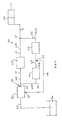
- a hydraulic system 30 (see figure 2 ) is provided to control and drive a hydraulic service of the working machine such as one or more of the or each actuator 24 of the working machine 10.
- Hydraulic system 30 includes a hydraulic pump 32 driven by the engine and having a pump outlet 60 and a pump inlet 65 in fluid communication with a source of hydraulic fluid 34 in the form of a tank.
- the hydraulic pump supplies pressurised fluid to a hydraulic service (in this case an actuator 24) primarily via main orifice 43 as described below.
- the hydraulic system has a main fluid path 61 and a secondary fluid path 62.
- the main fluid path is in fluid communication with the pump outlet 60 and includes a main orifice 43.
- the secondary fluid path 62 is in parallel with the main orifice 43.
- the secondary fluid path includes a flow (or pilot) orifice 44 and an amplification orifice 45 in series with the flow orifice.
- Means 63 is capable of generating an output signal representative of the fluid pressure in the secondary fluid path 62 between the flow orifice 44 and the amplification orifice 45 in this case means 63 is a port connected to pressure sensing line 66.
- a pump controller 64 is capable of controlling the pump flow in response to the output signal.
- the main orifice 43 is variable and at least one of the flow orifice 44 and amplification orifice 45 is a variable orifice.
- Pump 32 may be a variable displacement pump or it may be a fixed displacement pump.
- the pump controller 64 may act to vary the pump flow. For example where pump 32 is a variable displacement swash plate pump then the pump controller 64 may act to vary the angle of the swash plate, thereby varying the pump flow.
- the fixed displacement pump may include a bypass valve through which excess fluid flow can pass on route to a reservoir (or tank) of hydraulic fluid (such as source of hydraulic fluid 34).
- the pump controller 64 may vary the relief pressure of the bypass valve, thereby varying the amount of excess fluid flow that passes to tank.
- the main orifice 43 is a variable orifice, which may be variable between just two orifice areas, or it may be variable between two or more discreet orifice areas, or it may be continuously variable over a range of orifice areas.
- the smallest orifice area of the main orifice may be zero (i.e. the main orifice may be closable) or the smallest orifice area may be a non zero area (i.e. the main orifice may not be closable).
- the main orifice 43 may be varied manually or electrically, or via a pilot pressure.
- the flow orifice (or pilot orifice) 44 may be a fixed orifice or may be a variable orifice. When the flow orifice 44 is a variable orifice, it may be variable between just two orifice areas, or it may be variable between two or more discreet orifice areas, or it may be continuously variable over a range of orifice areas. When the flow orifice 44 is a variable orifice the smallest orifice area may be zero (i.e. the flow orifice may be closable) or the smallest orifice area may be a non zero area (i.e. the flow orifice may not be closable). Where flow orifice 44 is variable it may be varied manually, or electrically, or via a pilot pressure.
- the amplification orifice 45 may be a fixed orifice or may be a variable orifice. When the amplification orifice 45 is a variable orifice, it may be variable between just two orifice areas, or it may be variable between two or more discreet orifice areas, or it may be continuously variable over a range of orifice areas. When the amplification orifice 45 is a variable orifice the smallest orifice area may be a non zero area (i.e. the amplification orifice may not be closable). Where amplification orifice 45 is variable it may be varied manually, or electrically, or via a pilot pressure.
- main orifice 43, flow orifice 44 and amplification orifice 45 are variable, they may be varied together or they may be varied independently.
- the means 63 for generating an output signal representative of the fluid pressure in the secondary fluid path between the flow orifice and amplification orifice may be a tapping generating a pilot pressure signal or may be a pressure sensor that generates an electrical signal.
- the pump When the service is being operated the pump will be pumping hydraulic fluid along line 50, and line 61A, through the main orifice 43 along line 61B and line 51 to the service 24. Because there will be a pressure drop across the main orifice as the hydraulic fluid passes through the orifice then the pump outlet pressure will be higher than the service pressure, the difference between the pump outlet pressure and service pressure being the margin pressure.
- the pressure in the line 62B between the flow orifice will be less than the pump outlet pressure but will be greater than the service pressure.
- the pressure in the line 62B (the intermediate pressure) between the flow orifice and amp orifice can be varied and will be less than the pump outlet pressure but more than the service pressure.
- This intermediate pressure can then be communicated to the pump via line 66 so that the pump swash setting is controlled to match the flow demands.
- the present invention allows the system to be operated in a first mode and in a second mode such that the ratio is controlled differently in the first mode and the second mode.
- the first mode of operation defines a first mode ratio regime and the second mode defines a second mode ratio regime which is different from the first mode ratio regime.
- the cross section area of the flow orifice may be 3 mm 2 and the cross section area of the amplification orifice may be set to 4 mm 2 , giving a ratio of 3:4 i.e. 0.75.
- This ratio remains constant, setting a fixed valve margin pressure (in this case equivalent to the pump margin x (1 + 0.75 2 ), different to the pump margin pressure proportional to the ratio.
- the valve orifice 43 will have a relatively low margin pressure of about 1.56 times the pump margin pressure across it and hence this mode is suitable for precision work, such as grading.
- the ratio regime is to have a fixed ratio i.e. when operating in this mode the ratio does not change, i.e. the ratio remains constant.
- the cross section area of the flow orifice may be 3 mm 2 and the cross section area of the amplification orifice may be set to 1 mm 2 , giving a ratio of 3:1 i.e. 3.
- This ratio remains constant when operating the machine in this mode.
- the valve orifice 43 will have a relatively high margin pressure (about 10 times the pump margin) across it and hence this mode is suitable for fast work such as loading.
- the ratio regime is to have a fixed ratio i.e. when operating in this mode the ratio does not change, i.e. the ratio remains constant.
- the cross section area of the flow orifice may be 3 mm 2 and the cross section area of the amplification orifice may vary between 4 mm 2 at a relatively low displacement of an associated spool and 1.5 mm 2 at a relatively high displacement of an associated spool. Under these circumstances the ratio will vary between 3:4, i.e. 0.75 at relatively low displacements and 3:1, i.e. 3 at relatively high displacements.
- valve orifice 43 will have a relatively low margin (of about 1.56 times the pump margin pressure across it) at low spool displacement and will have a relatively high margin (of about 10 times the pump margin across it) at high spool displacement and hence this mode is suitable for precision work such as grading at low spool displacement and is suitable for fast work, such as loading at high spool displacement spool.
- the spool may typically be a control spool for controlling the service (such as an actuator). In this mode the ratio regime is to have a variable ratio i.e. when operating in this mode the ratio changes i.e. the ratio does not remain constant.
- the flow orifice cross section area is 3 mm 2 , i.e. the flow orifice cross section area is fixed.
- the ratio in three different ways (the ratio fixed at 0.75, the ratio fixed at 3, the ratio variable between 0.75 and 3) i.e. it is possible to have three different ratio regimes by being able to control the ratio in three different ways (i.e. by having three different ratio regimes) then the pressure at the means 63 and in hydraulic lines 66 can be controlled in three different ways allowing the valve margin pressure across orifice 43 to be controlled in three different ways.
- the amplification orifice is variable and the flow orifice is fixed and this equates to option 2 in table 1 above.
- the amplification orifice could be fixed and the flow orifice could be variable as in option 3 in table 1 above.
- the cross section area of the flow orifice may remain constant during operation in this mode.
- the cross section area of the flow orifice may remain constant at a different cross section area.
- the cross section area of the flow orifice may vary dependant upon a characteristic of machine (for example dependent upon the position of associated spool).
- both the flow orifice and the amplification orifice are variable.
- the cross section area of the flow orifice may be set to 2 mm 2 and the cross section area of the amplification orifice may be set to 4 mm 2 giving a ratio of 2:4 or 0.5. This ratio remains constant when operating the machine in this mode. In this mode the valve will have a relatively low pressure margin and hence this may be suitable for precision work, such as grading.
- the cross section area of the flow orifice may be set to 4 mm 2 and the cross section area of the amplification orifice may be set to 2 mm 2 giving a ratio of 4:2 i.e. 2. This ratio remains constant when operating the machine in this mode. In this mode the valve will have a relatively high margin and hence this mode is suitable for fast work such as loading.
- the cross section area of either the amplification orifice or the flow orifice or both orifices may vary depending upon a characteristic of the machine, for example depending upon the position of an associated spool.
- the cross section area of the amplification orifice may vary whilst cross section area of the flow orifice remains constant.
- the cross section area of the flow orifice may be variable whilst the cross section area of the amplification orifice remains constant.
- the cross section area of the amplification orifice may vary and the cross section area of the flow orifice may vary.
- the cross section area of the flow orifice to be variable and the cross section area of the amplification orifice to be variable allows the system to be operated in a first mode and in a second mode such that the ratio is controlled differently in the first mode and the second mode.
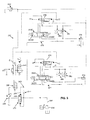
- Pump 232 is a fixed displacement pump.
- a bypass regulator 270 allows excess fluid flow to pass to tank and is controlled via a port 263 between the flow orifice 244 and amplification orifice 245 and pressure sensing line 266.
- the flow orifice and amplification orifice are in series with the amplification orifice being downstream of the flow orifice.
- main orifices 243A and 243B there are two main orifices 243A and 243B.
- the main orifice 243A is defined by orifice 243A1 and orifice 243A2 of control valve 271.
- Orifice 243B is defined by orifice 243B1 and 243B2 contained within control valve 272.
- Load sensing copy valve 277 is provided. Copy valves are known per se and act to replicate the pressure either side of the valve. Thus, the pressure at C is replicated by the copy valve such that the pressure at C' is the same as the pressure at C.
- Control valve 271 controls service 273 and control valve 272 controls service 274.
- a compensator 275 is associated with control valve 271 and a compensator 276 is associated with control valve 272.
- Compensators per se are known and act to reduce pressure being supplied to the associated service under certain conditions. Thus, for the purpose of explanation, it is assumed that service 273 requires a higher pressure than service 274. Accordingly, the spool of compensator 275 will be positioned as shown in figure 3 and when the control valve 271 is operated, then hydraulic fluid will pass through the control valve 271, through the compensator 275 (without any significant loss in pressure) through control valve 271 to service 273.
- the spool of compensator 276 will be positioned towards the left when viewing figure 3 i.e. the spool will move to the middle position shown and may move nearly to the fully closed position (the right hand box symbol) since the pressure at D in the hydraulic circuit will be less than the pressure at A and therefore the pressure at C' will cause the spool of the compensator to move left when viewing figure 3 . This will result in fluid flowing through compensator 276 dropping the pressure between A and D.
- Hydraulic system 330 includes a known drain regulator 280 which is arranged to drain trapped pressure when no service spool is actuated thus allowing pump pressure to fall back to a low standby value.
- Relief valves 281 and 282 are provided to protect service 274.
- Relief valves 283 and 284 are provided to protect service 273.
- Relief valve 285 acts to limit the pressure in line 266 but can be temporarily overridden by a "boost" valve 286, which, when actuated by the operator results in a pressure drop across the valve thereby enabling the pressure in line 266 to increase above the relief valve pressure setting of relief valve 285.
- This "boost" valve is used in circumstances where extra system pressure is temporarily required, for example, during a digging operation.
- the main orifice 243A and 243B are in fluid communication with the pump outlet. Each main orifice 243A and 243B supplies pressurised fluid to its associated service 273 and 274.
- the flow orifice 244 has a flow orifice inlet which senses a pressure representative of the pressure of the pump outlet, i.e. in this case it senses the pressure of the pump outlet.
- the flow orifice has an outlet.
- the amplification orifice 245 has an inlet in fluid communication with the flow orifice outlet.
- the amplification orifice outlet senses a pressure, C' representative of a pressure C at a service (in the above example, the pressure at service 273).
- Means in the form of port 263 generate an output signal representative of the fluid pressure between the flow orifice outlet and the amplification orifice inlet.
- a pump controller (in this case bypass regulator 270) controls the hydraulic pump in response to the output signal.
- the flow orifice defines a flow orifice cross section area in this case a fixed cross section area.
- the amplification orifice defines an amplification orifice cross section area, in this case a variable cross section area.
- the flow orifice cross section area and the amplification cross section area define a ratio.
- the main orifice 243A, 243B is variable. The ratio is variable (by virtue of varying the amplification orifice 245).
- the hydraulic system 30 can be operated in a first mode and in a second mode such that the ratio is controlled differently in the first mode and the second mode.
- the ratio is controlled differently by virtue of controlling the cross section area of the amplification orifice differently in the first and second modes.
- the amplification orifice can be controlled by maintaining the amplification orifice cross section area at a specified value.
- the amplification orifice may be maintained at a specified value different from the value when operating in first mode.
- the cross section area of the amplification orifice may be variable.
- the flow orifice may be variable.
- the amplification orifice may be fixed and the flow orifice may be variable.
- the flow orifice When the flow orifice is variable it may operate in a first mode where the cross section area of flow orifice is fixed.
- the system may operate in a second mode where the cross section area of the flow orifice is fixed at a different value to when operating the first mode.
- the system may operate in a mode where the cross section area of the flow orifice is variable.
- the bypass regulator 270 includes a spring 290 which sets a basic pump pressure margin.
- this basic setting may be relatively low, for example 4 bar.
- the pressure in line 266 acts to assist spring 290 thereby increasing the pump pressure i.e. the pump pressure will always be 4 bar higher than the pressure in line 266. Because the ratio of cross section areas between the flow orifice and amplification orifice can be varied depending upon which mode of operation this system is being operated under, then the pressure in line 266 varies depending upon the mode of operation in which the system is operating and hence the valve orifice 243A1 and 243B1 margin pressure can be varied depending upon the mode of operation in which the system is being operated.
- hydraulic system 330 With reference to figure 4 there is shown a further hydraulic system 330 with components that fulfil the same function as hydraulic system 230 being labelled 100 greater.
- hydraulic system 330 includes a variable pump with associated hydraulic circuitry whereas hydraulic system 230 has a fixed pump with associated hydraulic circuitry.
- pump 332 is a variable displacement pump.
- pump 332 has a swash plate 394, the angle of which is controlled by swash plate controller 395.
- the basic pump margin pressure is set by spring 390 and the spring pressure of spring 390 will be supplemented by the pressure in line 366 to increase the pump pressure as required.
- the hydraulic system 330 can operate in the first mode where the ratio of the cross section area of the flow orifice and amplification orifice is controlled in a first manner and can operate in a second mode where the ratio of the flow control orifice cross section area and amplification orifice cross section area is controlled in a second manner.
- the flow orifice may be variable.
- the amplification orifice may be fixed and the flow orifice may be variable.
- the flow orifice When the flow orifice is variable it may operate in a first mode where the cross section area of flow orifice is fixed.
- the system may operate in a second mode where the cross section area of the flow orifice is fixed at a different value to when operating the first mode.
- the system may operate in a mode where the cross section area of the flow orifice is variable.
- the outlet from the amplification orifice 45 senses the pressure representative of a pressure at service 24.
- the outlet of amplification orifice 45 senses the pressure by being in fluid communication with the service.
- the outlet from amplification orifice 245 and 345 which, whilst also sensing a pressure representative of a pressure at a service (in the example the pressure representative of pressure at the respective service 273, 373), the outlet from the amplification orifice 245 and 345 is not in fluid communication with respective service 273, 373.
- one ratio regime is to keep the ratio (or ratio value) fixed.
- the ratio value was 0.75 and this ratio value remained constant when operating the system in this mode.
- another, different ratio regime is to keep the ratio (or ratio value) fixed at a different value, in the example case the ratio value was 3 and this ratio value remained constant when operating the system in this mode.
- the regimes are different because the value of the ratio when operating under each regime is different.
- one ratio regime is to vary the ratio (or vary the ratio value).
- the example above the ratio value was varied between 0.86 and 2.
- another, different ratio regime would be to vary the ratio differently, for example the ratio could vary between 0.5 and 2 to provide a different ratio regime, the ratio could vary between 0.68 and 3 to provide a different ratio regime.
- the ratio regime has a variable ratio value
- the ratio value may vary dependent upon a first machine characteristic in a first ratio regime and may vary dependent upon a second machine characteristic in a second ratio regime.
Landscapes
- Engineering & Computer Science (AREA)
- General Engineering & Computer Science (AREA)
- Mechanical Engineering (AREA)
- Physics & Mathematics (AREA)
- Fluid Mechanics (AREA)
- Mining & Mineral Resources (AREA)
- Civil Engineering (AREA)
- Structural Engineering (AREA)
- Fluid-Pressure Circuits (AREA)
- Operation Control Of Excavators (AREA)
Applications Claiming Priority (1)
| Application Number | Priority Date | Filing Date | Title |
|---|---|---|---|
| GB1207161.9A GB2501486A (en) | 2012-04-24 | 2012-04-24 | Work machine having a hydraulic system comprising variable orifice ratios |
Publications (2)
| Publication Number | Publication Date |
|---|---|
| EP2657537A2 true EP2657537A2 (de) | 2013-10-30 |
| EP2657537A3 EP2657537A3 (de) | 2016-03-09 |
Family
ID=46261777
Family Applications (1)
| Application Number | Title | Priority Date | Filing Date |
|---|---|---|---|
| EP13162367.0A Withdrawn EP2657537A3 (de) | 2012-04-24 | 2013-04-04 | Hydraulisches System |
Country Status (5)
| Country | Link |
|---|---|
| US (1) | US20130280097A1 (de) |
| EP (1) | EP2657537A3 (de) |
| JP (1) | JP2013228101A (de) |
| CN (1) | CN103375450A (de) |
| GB (1) | GB2501486A (de) |
Families Citing this family (9)
| Publication number | Priority date | Publication date | Assignee | Title |
|---|---|---|---|---|
| US9435105B2 (en) * | 2014-05-07 | 2016-09-06 | Deere & Company | Method and system for controlling pump outlet pressure between different operating modes |
| US10378184B2 (en) | 2015-06-16 | 2019-08-13 | Volvo Construction Equipment Ab | Load sensing hydraulic system for a working machine |
| US9662787B1 (en) * | 2015-09-25 | 2017-05-30 | Google Inc. | Hydraulic pressure variation in a legged robot |
| US10323458B2 (en) * | 2016-10-21 | 2019-06-18 | Caterpillar Inc. | Dual pressure logic for a track drill circuit |
| US11530524B2 (en) | 2021-01-29 | 2022-12-20 | Cnh Industrial America Llc | System and method for controlling hydraulic fluid flow within a work vehicle |
| US11261582B1 (en) | 2021-01-29 | 2022-03-01 | Cnh Industrial America Llc | System and method for controlling hydraulic fluid flow within a work vehicle using flow control valves |
| US11313388B1 (en) | 2021-01-29 | 2022-04-26 | Cnh Industrial America Llc | System and method for controlling hydraulic fluid flow within a work vehicle |
| US11143211B1 (en) | 2021-01-29 | 2021-10-12 | Cnh Industrial America Llc | System and method for controlling hydraulic fluid flow within a work vehicle |
| US11921525B1 (en) | 2022-11-25 | 2024-03-05 | Pratt & Whitney Canada Corp. | System and method for controlling fluid flow with a pressure relief valve |
Family Cites Families (24)
| Publication number | Priority date | Publication date | Assignee | Title |
|---|---|---|---|---|
| US4196588A (en) * | 1978-05-01 | 1980-04-08 | Caterpillar Tractor Co. | Margin valve |
| JPS54162353A (en) * | 1978-06-13 | 1979-12-22 | Toshiba Corp | Hydraulic circuit for driving cargo handling apparatus |
| DE2906166A1 (de) * | 1979-02-17 | 1980-08-28 | Bosch Gmbh Robert | Einrichtung zur regelung des foerderstroms und zur begrenzung des foerderdrucks einer verstellbaren pumpe |
| US4327627A (en) * | 1980-01-07 | 1982-05-04 | Tadeusz Budzich | Load responsive fluid control valve |
| DE3722083C1 (de) * | 1987-07-03 | 1988-09-15 | Heilmeier & Weinlein | Hydraulische Steuervorrichtung |
| DE3807583C1 (de) * | 1988-03-08 | 1989-03-09 | Heilmeier & Weinlein Fabrik Fuer Oel-Hydraulik Gmbh & Co Kg, 8000 Muenchen, De | |
| DE3844401C2 (de) * | 1988-12-30 | 1994-10-06 | Rexroth Mannesmann Gmbh | Regeleinrichtung für eine Verstellpumpe |
| DE4313597B4 (de) * | 1993-04-26 | 2005-09-15 | Linde Ag | Verfahren zum Betreiben einer verstellbaren hydrostatischen Pumpe und dafür ausgebildetes hydrostatisches Antriebssystem |
| US5579642A (en) * | 1995-05-26 | 1996-12-03 | Husco International, Inc. | Pressure compensating hydraulic control system |
| US5809862A (en) * | 1995-08-04 | 1998-09-22 | Dallman; Jimmie J. | Flotation control system |
| US6033188A (en) * | 1998-02-27 | 2000-03-07 | Sauer Inc. | Means and method for varying margin pressure as a function of pump displacement in a pump with load sensing control |
| GB2352275B (en) * | 1999-07-17 | 2004-02-18 | Agco Gmbh & Co | Hydraulic system for utility vehicles |
| JP4128482B2 (ja) * | 2002-04-30 | 2008-07-30 | 東芝機械株式会社 | 油圧制御システム |
| US6662558B1 (en) * | 2002-07-02 | 2003-12-16 | Caterpillar Inc | Variable delivery control arrangement for a pump |
| US6874318B1 (en) * | 2003-09-18 | 2005-04-05 | Sauer-Danfoss, Inc. | Automatic remote pressure compensation in an open circuit pump |
| US7204185B2 (en) * | 2005-04-29 | 2007-04-17 | Caterpillar Inc | Hydraulic system having a pressure compensator |
| GB2436856A (en) * | 2006-04-07 | 2007-10-10 | Agco Gmbh | Pressure control for system with primary and secondary consumers |
| US8478504B2 (en) * | 2008-10-23 | 2013-07-02 | Volvo Compact Equipment Sas | Skid steer machine with automatic operating ratio change system |
| SE534002C2 (sv) * | 2009-06-24 | 2011-03-29 | Nordhydraulic Ab | Förfarande och anordning för styrning av ett hydraliskt system |
| GB0912540D0 (en) * | 2009-07-20 | 2009-08-26 | Bamford Excavators Ltd | Hydraulic system |
| CN201553113U (zh) * | 2009-08-27 | 2010-08-18 | 天津建筑机械厂 | 一种履带式牵引机的液压系统 |
| JP2011075048A (ja) * | 2009-09-30 | 2011-04-14 | Hitachi Constr Mach Co Ltd | 油圧建設機械の油圧駆動装置 |
| DE102009049548A1 (de) * | 2009-10-16 | 2011-04-21 | Hydac Fluidtechnik Gmbh | Ventilanordnung |
| CN103154389A (zh) * | 2010-07-06 | 2013-06-12 | 沃尔沃建造设备有限公司 | 混合动力挖掘机的马力控制系统及其控制方法 |
-
2012
- 2012-04-24 GB GB1207161.9A patent/GB2501486A/en not_active Withdrawn
-
2013
- 2013-04-04 EP EP13162367.0A patent/EP2657537A3/de not_active Withdrawn
- 2013-04-19 US US13/866,757 patent/US20130280097A1/en not_active Abandoned
- 2013-04-22 JP JP2013089397A patent/JP2013228101A/ja active Pending
- 2013-04-24 CN CN2013101460436A patent/CN103375450A/zh active Pending
Also Published As
| Publication number | Publication date |
|---|---|
| JP2013228101A (ja) | 2013-11-07 |
| GB2501486A (en) | 2013-10-30 |
| US20130280097A1 (en) | 2013-10-24 |
| GB201207161D0 (en) | 2012-06-06 |
| EP2657537A3 (de) | 2016-03-09 |
| CN103375450A (zh) | 2013-10-30 |
Similar Documents
| Publication | Publication Date | Title |
|---|---|---|
| EP2657537A2 (de) | Hydraulisches System | |
| US7320216B2 (en) | Hydraulic system having pressure compensated bypass | |
| JP5179364B2 (ja) | 面積制御されるバイパスを有する油圧システム | |
| US10526767B2 (en) | Construction machine | |
| US9429175B2 (en) | Pressure compensated hydraulic system having differential pressure control | |
| US9133605B2 (en) | Flow sensing based variable pump control technique in a hydraulic system with open center control valves | |
| JP6304273B2 (ja) | 作業機械の油圧駆動装置 | |
| EP2171286A1 (de) | Verfahren und hydraulische steueranordnung zur druckmittelversorgung zumindest eines hydraulischen verbrauchers | |
| KR101770672B1 (ko) | 건설기계의 유압 구동 장치 | |
| JP2009510357A (ja) | 圧力補償を増補した液圧システム | |
| US8752371B2 (en) | Independent metering valve with flow limiter | |
| US7481052B2 (en) | Fluid circuit with multiple flows from a series valve | |
| JP2004197825A (ja) | 液圧駆動装置 | |
| US10072396B2 (en) | Working machine control system | |
| US11142888B2 (en) | Hydraulic machine | |
| EP3581717A1 (de) | Hydraulische antriebsvorrichtung für eine baumaschine | |
| JP2008224039A (ja) | 油圧駆動機械の制御装置 | |
| US10208457B2 (en) | Working machine control system | |
| DE102011107222A1 (de) | Hydrostatisches Antriebssystem mit einer im Fördervolumen verstellbaren Pumpe | |
| KR20180082103A (ko) | 농업용 작업차량의 작업기 승강 및 유압 취출을 위한 유압장치 | |
| CN110836209B (zh) | 液压控制阀 | |
| US11078932B2 (en) | Hydraulic machine | |
| CN112664496A (zh) | 液压控制装置和施工机械 | |
| JPH01247805A (ja) | 油圧駆動装置 |
Legal Events
| Date | Code | Title | Description |
|---|---|---|---|
| PUAI | Public reference made under article 153(3) epc to a published international application that has entered the european phase |
Free format text: ORIGINAL CODE: 0009012 |
|
| AK | Designated contracting states |
Kind code of ref document: A2 Designated state(s): AL AT BE BG CH CY CZ DE DK EE ES FI FR GB GR HR HU IE IS IT LI LT LU LV MC MK MT NL NO PL PT RO RS SE SI SK SM TR |
|
| AX | Request for extension of the european patent |
Extension state: BA ME |
|
| PUAL | Search report despatched |
Free format text: ORIGINAL CODE: 0009013 |
|
| AK | Designated contracting states |
Kind code of ref document: A3 Designated state(s): AL AT BE BG CH CY CZ DE DK EE ES FI FR GB GR HR HU IE IS IT LI LT LU LV MC MK MT NL NO PL PT RO RS SE SI SK SM TR |
|
| AX | Request for extension of the european patent |
Extension state: BA ME |
|
| RIC1 | Information provided on ipc code assigned before grant |
Ipc: F15B 11/16 20060101AFI20160204BHEP |
|
| STAA | Information on the status of an ep patent application or granted ep patent |
Free format text: STATUS: THE APPLICATION IS DEEMED TO BE WITHDRAWN |
|
| 18D | Application deemed to be withdrawn |
Effective date: 20160910 |