EP2656934B1 - Train de laminoir multiple élevé équipé d'une fonction de cylindres de travail - Google Patents
Train de laminoir multiple élevé équipé d'une fonction de cylindres de travail Download PDFInfo
- Publication number
- EP2656934B1 EP2656934B1 EP13002094.4A EP13002094A EP2656934B1 EP 2656934 B1 EP2656934 B1 EP 2656934B1 EP 13002094 A EP13002094 A EP 13002094A EP 2656934 B1 EP2656934 B1 EP 2656934B1
- Authority
- EP
- European Patent Office
- Prior art keywords
- strip
- rolling mill
- roll
- rolls
- shift
- Prior art date
- Legal status (The legal status is an assumption and is not a legal conclusion. Google has not performed a legal analysis and makes no representation as to the accuracy of the status listed.)
- Active
Links
- 238000005096 rolling process Methods 0.000 title claims description 94
- 239000002184 metal Substances 0.000 claims description 10
- 230000008878 coupling Effects 0.000 claims description 7
- 238000010168 coupling process Methods 0.000 claims description 7
- 238000005859 coupling reaction Methods 0.000 claims description 7
- 238000006073 displacement reaction Methods 0.000 claims description 5
- 230000000149 penetrating effect Effects 0.000 claims description 2
- 239000000463 material Substances 0.000 description 9
- 238000000034 method Methods 0.000 description 9
- 230000009467 reduction Effects 0.000 description 7
- 230000008569 process Effects 0.000 description 6
- 238000009966 trimming Methods 0.000 description 6
- 238000003462 Bender reaction Methods 0.000 description 5
- 230000001133 acceleration Effects 0.000 description 4
- 238000009826 distribution Methods 0.000 description 4
- 230000007246 mechanism Effects 0.000 description 3
- 230000008901 benefit Effects 0.000 description 2
- 244000145845 chattering Species 0.000 description 2
- 238000007796 conventional method Methods 0.000 description 2
- 230000007423 decrease Effects 0.000 description 2
- 238000009434 installation Methods 0.000 description 2
- 238000004519 manufacturing process Methods 0.000 description 2
- 229910000976 Electrical steel Inorganic materials 0.000 description 1
- 229910000831 Steel Inorganic materials 0.000 description 1
- 230000008859 change Effects 0.000 description 1
- 238000005520 cutting process Methods 0.000 description 1
- 230000000694 effects Effects 0.000 description 1
- 229910001220 stainless steel Inorganic materials 0.000 description 1
- 239000010935 stainless steel Substances 0.000 description 1
- 239000010959 steel Substances 0.000 description 1
Images


Classifications
-
- B—PERFORMING OPERATIONS; TRANSPORTING
- B21—MECHANICAL METAL-WORKING WITHOUT ESSENTIALLY REMOVING MATERIAL; PUNCHING METAL
- B21B—ROLLING OF METAL
- B21B13/00—Metal-rolling stands, i.e. an assembly composed of a stand frame, rolls, and accessories
- B21B13/14—Metal-rolling stands, i.e. an assembly composed of a stand frame, rolls, and accessories having counter-pressure devices acting on rolls to inhibit deflection of same under load; Back-up rolls
- B21B13/142—Metal-rolling stands, i.e. an assembly composed of a stand frame, rolls, and accessories having counter-pressure devices acting on rolls to inhibit deflection of same under load; Back-up rolls by axially shifting the rolls, e.g. rolls with tapered ends or with a curved contour for continuously-variable crown CVC
-
- B—PERFORMING OPERATIONS; TRANSPORTING
- B21—MECHANICAL METAL-WORKING WITHOUT ESSENTIALLY REMOVING MATERIAL; PUNCHING METAL
- B21B—ROLLING OF METAL
- B21B13/00—Metal-rolling stands, i.e. an assembly composed of a stand frame, rolls, and accessories
- B21B13/14—Metal-rolling stands, i.e. an assembly composed of a stand frame, rolls, and accessories having counter-pressure devices acting on rolls to inhibit deflection of same under load; Back-up rolls
- B21B13/147—Cluster mills, e.g. Sendzimir mills, Rohn mills, i.e. each work roll being supported by two rolls only arranged symmetrically with respect to the plane passing through the working rolls
-
- B—PERFORMING OPERATIONS; TRANSPORTING
- B21—MECHANICAL METAL-WORKING WITHOUT ESSENTIALLY REMOVING MATERIAL; PUNCHING METAL
- B21B—ROLLING OF METAL
- B21B2267/00—Roll parameters
- B21B2267/18—Roll crown; roll profile
-
- B—PERFORMING OPERATIONS; TRANSPORTING
- B21—MECHANICAL METAL-WORKING WITHOUT ESSENTIALLY REMOVING MATERIAL; PUNCHING METAL
- B21B—ROLLING OF METAL
- B21B2269/00—Roll bending or shifting
- B21B2269/12—Axial shifting the rolls
- B21B2269/14—Work rolls
-
- B—PERFORMING OPERATIONS; TRANSPORTING
- B21—MECHANICAL METAL-WORKING WITHOUT ESSENTIALLY REMOVING MATERIAL; PUNCHING METAL
- B21B—ROLLING OF METAL
- B21B31/00—Rolling stand structures; Mounting, adjusting, or interchanging rolls, roll mountings, or stand frames
- B21B31/16—Adjusting or positioning rolls
- B21B31/18—Adjusting or positioning rolls by moving rolls axially
Definitions
- the present invention relates to a multi-high rolling mill having small-diameter work rolls for performing rolling of a hard material, such as a stainless steel strip or an electrical steel strip, the rolling mill being equipped with a work roll shift function to shift the work rolls tapered at one ends in the axial directions, thereby controlling edge drop of a material to be rolled or controlling a strip shape.
- a hard material such as a stainless steel strip or an electrical steel strip
- EP 2 292 341 A2 discloses a multi-high rolling mill having all features of the pre-characterising portion of present claim 1.
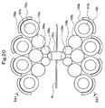
- the structure of a thrust bearing of a work roll of a six-high rolling mill or a 12-high or 20-high cluster-type rolling mill using small-diameter work rolls, as shown in Figs. 20 and 21 is such that end faces of one ends of an upper work roll 100a and a lower work roll 100b are supported by a single vertically-barrel thrust bearing 101a or 101b on each of an operation side and a drive side, because of limited installation space.
- the thrust bearings 101a and 101b are rotatably supported by brackets 102a and 102b, each formed in a groove shape in cross section, via vertical shafts 103a and 103b.
- Figs. 20 and 21 show an example where a metal strip W, which is a material to be rolled, is rolled by the pair of upper and lower work rolls 100a and 100b of a 20-high cluster-type rolling mill.
- the pair of upper and lower work rolls 100a and 100b are supported in contact with two upper and two lower first intermediate rolls 104a and 104b.
- These two upper and two lower first intermediate rolls 104a and 104b are supported in contact with three upper and three lower second intermediate rolls 105a and 105b.
- These three upper and three lower second intermediate rolls 105a and 105b are supported in contact with four upper and four lower backing bearing shafts formed of backing bearings 106a and 106b, shafts 107a and 107b, and saddles 108a and 108b, respectively.
- an object of the present invention is to provide a multi-high rolling mill equipped with a work roll shift function where thrust bearings are effectively installed so that the shifting function of small-diameter work rolls can be achieved with a simple mechanism.
- a multi-high rolling mill equipped with a work roll shift function for solving the above problems is a rolling mill including a pair of upper and lower work rolls for rolling a metal strip, and one or a plurality of upper support rolls and one or a plurality of lower support rolls supporting the work rolls, characterized in that the pair of upper and lower work rolls are provided with tapered portions in upper and lower positions in point symmetry; end faces of the respective work rolls are supported by two upper and two lower thrust bearings on each of an operation side and a drive side; long holes are formed in inner-race side shafts of bearing boxes pivotally supporting the respective thrust bearings, the long holes allowing the thrust bearings to be individually movable together with the respective bearing boxes in roll axial directions; coupling bars penetrating the corresponding long holes to restrict vertical displacements of the two upper and two lower thrust bearings are provided between the corresponding bearing boxes; first roll shift devices connected to the respective bearing boxes to shift the corresponding work rolls in the roll axial directions are provided; and taper start positions of the tape
- the multi-high rolling mill equipped with a work roll shift function is characterized in that a ratio D/B (D: bearing outer diameter, B: bearing width) of an outer diameter of the thrust bearings to a width of the thrust bearings is set to a range between 5.0 to 12.
- the multi-high rolling mill equipped with a work roll shift function is characterized in that guides are provided for guiding the respective bearing boxes, on the opposite side to the thrust bearings, slidably in the roll axial directions and collectively while restricting the respective bearing boxes in vertical, entry-side and delivery-side Passing directions.
- each of the first roll shift devices comprises: an arm joined at a middle portion thereof to the corresponding bearing box via a pin, and a shift cylinder for applying shift force to one end of the arm using a hinge coupled to the other ends of the arms as a fulcrum.
- the multi-high rolling mill equipped with a work roll shift function is characterized in that a strip widthwise end position detector for a metal strip is provided on an entry side or a delivery side of the rolling mill, and a control means for performing shift controls of the first roll shift devices is provided to cause the taper start positions of the tapered portions of the upper and lower work rolls to coincide with the vicinities of the insides of the strip widthwise ends or the vicinities of the outsides of the strip widthwise ends detected by the strip widthwise end position detector independently for the upper side and the lower side.
- the multi-high rolling mill equipped with a work roll shift function is characterized in that a strip widthwise end thickness meter for measuring thicknesses of the strip widthwise ends of a metal strip is provided on a delivery side of the rolling mill, and a control means for performing shift controls of the first roll shift devices is provided in order to adjust the taper start positions of the tapered portions of the upper and lower work rolls in the vicinities of the insides of the strip widthwise ends individually for the upper side and the lower side such that the thicknesses of the strip widthwise ends measured on the operation side and on the drive side become predetermined thicknesses.
- the multi-high rolling mill equipped with a work roll shift function is characterized in that second roll shift devices are further provided for shifting the one or plurality of upper support rolls and the one or plurality of lower support rolls in the roll axial directions, and the control means performs shift controls of the second roll shift devices to shift-control the one or plurality of upper support rolls and the one or plurality of lower support rolls asymmetrically on the operation side and on the drive side.
- the two upper and lower thrust bearings have the long-hole structures allowing the respective thrust bearings to move individually in the roll axial directions at the inner-race side shafts, and the coupling bars for restricting vertical displacements of the respective thrust bearings are provided. Therefore, the bearing stiffness of the thrust bearings can be increased. Further, the ratio D/B (D: thrust bearing outer diameter, B: thrust bearing width) of each of the thrust bearings of the work rolls has been changed from a conventional ratio (D/B: 2.0 to 3.0) to a ratio of 2.5 to 4.0 times (D/B: 5.0 to 12) the conventional ratio. Therefore, even if the thrust bearing width B is narrower, a bearing life equal to or longer than a conventional bearing life can be obtained.
- D/B thrust bearing outer diameter
- B thrust bearing width
- the guides are provided for guiding the bearing boxes, on the opposite side to the thrust bearings, slidably in the roll axial directions and collectively under restriction in vertical and entry and delivery directions, the stiffness of this part can be raised. As a result, this configuration makes it possible to withstand large external force at the time of strip cutting, and also prevent chattering due to vibration from occurring.
- the first roll shift devices include the arms joined at middle portions thereof to the bearing boxes via the pins, and the shift cylinders for applying shift force to one ends of the arms using the hinges coupled to the other ends of the arms as fulcrums. Therefore, even if the capacities of the cylinders are smaller than those of cylinders having a linear structure, the arm ratio makes it possible to secure a predetermined shift force, and consequently the cylinders can be installed even in narrow spaces.
- the amount of edge drop which is a reduction in the strip thickness of the strip widthwise end, can be reduced more effectively. Therefore, the amount of edge trimming in the following process is reduced, and the yield is improved.
- the amount of edge drop which is a reduction in the strip thickness of the strip widthwise end, can be reduced more effectively, and consequently the edge trimming amount in the following process is reduced, and the yield is improved.
- the meandering causes the strip shape to be asymmetrical on the operation side and on the drive side
- by shift-controlling the pair of or the plurality of pairs of upper and lower support rolls asymmetrically on the operation side and on the drive side by the second roll shift devices rolling into a symmetrical shape on the operation side and on the drive side is made possible, and therefore stable rolling can be realized.
- Fig. 1 is a front view of a 20-high cluster-type rolling mill according to a first example
- Fig. 2 is an arrow sectional view taken along the lines II-II of Fig. 1
- Fig. 3 is an arrow sectional view taken along the lines III-III of Fig. 2
- Fig. 4 is an arrow sectional view taken along the lines IV-IV of Fig. 1
- Fig. 5 is an arrow sectional view taken along the lines V-V of Fig. 4
- Fig. 6 is an arrow sectional view taken along the lines VI-VI of Fig. 4
- Fig. 7 is an arrow sectional view taken along the lines VII-VII of Fig.
- Figs 8A and 8B are graphs of results of comparison of strip shape variation relative to load variation
- Fig. 8A is a graph showing a calculation result of strip shape variation relative to load variation in a conventional technique
- Fig. 8B is a graph showing a calculation result of strip shape variation relative to load variation in the present invention.
- a rolling mill of the first example is a 20-high cluster-type rolling mill as shown in Figs. 1 to 3 , and a metal strip (hereinafter simply called strip) W, which is a material to be rolled, is rolled by a pair of upper and lower work rolls 2a and 2b.
- strip W a metal strip (hereinafter simply called strip) W, which is a material to be rolled
- This pair of upper and lower work rolls 2a and 2b are supported in contact with two upper and two lower first intermediate rolls 3a and 3b, respectively. These two upper and two lower first intermediate rolls 3a and 3b are supported in contact with three upper and three lower second intermediate rolls 4a and 4b, respectively. These three upper and three lower second intermediate rolls 4a and 4b are supported in contact with four upper and four lower backing bearing shafts formed of backing bearings 5a and 5b, shafts 6a and 6b, and saddles 7a and 7b. The four upper backing bearing shafts are supported at the saddles 7a by a top inner housing 17a.
- the top inner housing 17a is supported on lower faces of upper beams of outer housings 20a and 20b provided respectively on an operation side and on a drive side via pass line adjusters 18a and 18b, such as a worm jack or a taper wedge and a stepped rocker plate.
- the pass line adjusters 18a and 18b may incorporate load cells to measure rolling loads.
- the four lower backing bearing shafts are supported at the saddles 7b by a bottom inner housing 17b.
- the bottom inner housing 17b is supported on upper faces of lower beams of the outer housings 20a and 20b via push-up cylinders 19a and 19b. These push-up cylinders 19a and 19b generate a rolling load.
- the two upper and two lower first intermediate rolls 3a and 3b have tapered portions (see taper start positions SP) located in upper and lower positions in point symmetry and on the opposite sides respectively to tapered portions 22a and 22b of the work rolls 2a and 2b which are in contact with the first intermediate rolls 3a and 3b, and can be shifted in roll axial directions by unillustrated second roll shift devices.
- the pair of upper and lower work rolls 2a and 2b are provided with the tapered portions 22a and 22b at upper and lower positions in point symmetry, and besides, operation-side end faces and drive side end faces of these upper and lower work rolls 2a and 2b are supported by two upper and lower thrust bearings 8a and 8b and two upper and lower thrust bearings 8c and 8d.
- inner-race side shafts 37a, 37b, 37c, and 37d of bearing boxes 10a, 10b, 10c, and 10d, which pivotally support the respective thrust bearings 8a, 8b, 8c, and 8d have long holes 38a, 38b, 38c, and 38d formed therein allowing the respective thrust bearings 8a, 8b, 8c, and 8d to move individually together with the respective bearing boxes 10a, 10b, 10c, and 10d in the roll axial directions.
- coupling bars 9a and 9b are provided between the bearing boxes 10a and 10b and between the bearing boxes 10c and 10d, respectively. The coupling bars 9a and 9b each penetrate the corresponding long holes 38a and 38b or 38c and 38d, to restrict vertical displacements of the corresponding two upper and lower thrust bearings 8a and 8b or 8c and 8d.
- the ratio D/B (D: bearing outer diameter, B: bearing width) of the outer diameter of each thrust bearing 8a, 8b, 8c, 8d to the width of the thrust bearing 8a, 8b, 8c, 8d is set between 5.0 and 12 (see Fig. 6 ).
- guides 16a, 16b, 16c, and 16d are provided for guiding the respective bearing boxes 10a, 10b, 10c, and 10d, on the opposite side to the thrust bearings 8a, 8b, 8c, 8d, slidably in the roll axial directions and collectively while restricting the bearing boxes 10a, 10b, 10c, and 10d in vertical and entry/delivery directions (see Fig. 5 ). It should be noted that these guides may be guide rods or bush structures.
- first roll shift devices connected to the respective bearing boxes 10a, 10b, 10c, and 10d to shift the respective work rolls 2a and 2b in the roll axial directions are provided.
- These first roll shift devices are formed of arms 13a, 13b, 13c, and 13d and shift cylinders 11a, 11b, 11c, and 11d.
- the arms 13a, 13b, 13c, and 13 are joined at middle portions thereof to the bearing boxes 10a, 10b, 10c, and 10d via pins 14a, 14b, 14c, and 14d, and the shift cylinders 11a, 11b, 11c, and 11d are joined to one ends of the arms 13a, 13b, 13c, and 13d via pins 12a, 12b, 12c, and 12d for applying shift force thereto using hinges 15a, 15b, 15c, and 15d coupled to the other ends of the arms 13a, 13b, 13c, and 13d as fulcrums (see Fig. 4 ).
- the first roll shift devices shift taper start positions SP of the tapered portions 22a and 22b of the respective work rolls 2a and 2b to an inner vicinity of strip widthwise ends or an outer vicinity of the strip widthwise ends.
- the two, upper and lower, thrust bearings 8a and 8b, and the two, upper and lower, thrust bearings 8c and 8d have the long-hole 38a, 38b, 38c and 38d structures allowing the respective thrust bearings 8a, 8b, 8c, and 8d to move individually in the roll axial directions at the inner-race side shafts 37a and 37b, 37c and 37d, and are provided with the coupling bars 9a and 9b restricting displacements of the thrust bearings 8a, 8b, 8c, and 8d in the vertical direction of the bearing boxes 10a, 10b, 10c, and 10d of the respective thrust bearings 8a, 8b, 8c, and 8d. Therefore, the bearing stiffness of the thrust bearings can be increased.
- the ratio D/B (D: thrust bearing outer diameter, B: thrust bearing width) of each thrust bearing 8a, 8b, 8c, 8d has been changed from a conventional ratio (D/B: 2.0 to 3.0) to a ratio of 2.5 to 4.0 times (D/B: 5.0 to 12) the conventional ratio. Therefore, even if the thrust bearing width B is narrower, a bearing life equal to or longer than a conventional bearing life can be obtained.
- the guides 16a, 16b, 16c, and 16d are provided for guiding the respective bearing boxes 10a, 10b, 10c, and 10d, on the opposite side to the thrust bearings 8a to 8d, slidably in the roll axial directions and collectively while restricting the bearing boxes 10a, 10b, 10c, and 10d vertical and entry and delivery directions, the stiffness of this part can be raised.
- this configuration makes it possible to withstand large external force at the time of strip breakage, and also prevent chattering due to vibration from occurring.
- the first roll shift devices are formed of the arms 13a, 13b, 13c, and 13d joined at middle portions thereof to the respective bearing boxes 10a, 10b, 10c, and 10d via the pins 14a, 14b, 14c, and 14d, and the shift cylinders 11a, 11b, 11c, and 11d for applying shift force to one ends of the arms 13a, 13b, 13c, and 13d using the hinges 15a, 15b, 15c, and 15d coupled to the other ends of the arms 13a, 13b, 13c, and 13d as fulcrums. Therefore, even if the capacities of the cylinders are smaller than those of cylinders having a linear structure, the arm ratio makes it possible to secure a predetermined shift force, and consequently the cylinders can be installed even in narrow spaces.
- the thrust bearings 8a, 8b, 8c, and 8d are effectively incorporated, so that the shifting functions of the small-diameter work rolls 2a and 2b can be achieved by the roll shift devices having simple structures.
- the taper start positions SP of the tapered portions 22a and 22b, disposed in upper and lower positions in point symmetry, of the pair of upper and lower work rolls 2a and 2b can be shifted to the vicinities of the insides of the strip widthwise ends.
- taper start positions SP of the tapered portions 22a and 22b of the work rolls 2a and 2b are shifted to the vicinities of the outsides of the strip widthwise ends (in the example shown in Fig. 2 , taper start positions SP of tapered portions of the first intermediate rolls 3a and 3b are also shifted to the vicinities of the outsides of the strip widthwise ends), undesirable contact linear pressure from the outside of the strip width to the work rolls 2a and 2b, caused by the first intermediate rolls 3a and 3b, is reduced, so that shape stability (small shape variation relative to load variation) is improved.
- Figs. 8A and 8B the shape stability (small shape variation relative to load variation) will be described by using Figs. 8A and 8B as to a case where the taper start positions SP of the tapered portions 22a and 22b of the work rolls 2a and 2b have been shifted so as to coincide with the vicinities of the outsides of the strip widthwise ends.
- Fig. 8A shows a case of the conventional straight work rolls 100a shown in Fig. 21 .
- the load changes by 2.1 times from 400 tons to 820 tons
- the shape changes by 250 I-units.
- Fig. 8B shows a case where the taper start positions SP of the tapered portions 22a and 22b of the work rolls 2a and 2b have been caused to coincide with the vicinities of the outsides of the strip widthwise ends.
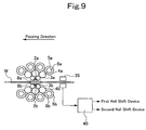
- Fig. 9 is a front view of a 20-high cluster-type rolling mill according to a second example of the present invention
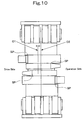
- Fig. 10 is a descriptive view of strip meandering according to the second example
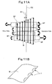
- Figs. 11A and 11B are descriptive views showing the necessity of an asymmetrical control means in case of strip meandering
- Fig. 11A is a descriptive view of a linear pressure distribution in material
- Fig. 11B is a descriptive view of a strip shape
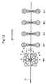
- Fig. 12 is a side view showing an example of application of the second example to a tandem rolling mill.
- the second example is an example where a strip widthwise end position detector 35 for a strip W is provided on the entry side (or the delivery side) of a 20-high cluster-type rolling mill, and a controller (control means) 40 is provided to perform shift controls of the first roll shift devices for the work rolls 2a and 2b of the first example to cause the taper start positions SP of the upper and lower work rolls 2a and 2b of the first example to coincide with the vicinities of the insides of the strip widthwise ends or the vicinities of the outsides of the strip widthwise ends detected by the strip widthwise end position detector 35 independently for the upper side and the lower side.
- a controller (control means) 40 is provided to perform shift controls of the first roll shift devices for the work rolls 2a and 2b of the first example to cause the taper start positions SP of the upper and lower work rolls 2a and 2b of the first example to coincide with the vicinities of the insides of the strip widthwise ends or the vicinities of the outsides of the strip widthwise ends detected by the strip
- the taper start positions SP of the work rolls 2a and 2b to coincide with the vicinities of the insides of the strip widthwise ends from actual strip widthwise ends detected by the strip widthwise end position detector 35, the amount of edge drop, which is a reduction in strip thickness of the strip widthwise end, can be reduced more effectively against meandering of a strip 1 during rolling.
- the taper start positions SP of the work rolls 2a and 2b to coincide with the vicinities of the outsides of the strip widthwise ends from actual strip widthwise ends detected by the strip widthwise end position detector 35, the undesirable contact linear pressure from the outsides of the strip width to the work rolls 2a and 2b from the first intermediate rolls 3a and 3b are reduced more effectively against meandering of the strip W during rolling, and therefore the shape stability (small shape variation relative to load variation) is significantly improved.
- upper-lower asymmetrical shifting of the two upper and two lower first intermediate rolls 3a and 3b is performed. Specifically, in this case, the taper start position SP of each upper first intermediate roll 3a is shifted toward the drive side, and the taper start position SP of each lower first intermediate roll 3b is also shifted toward the drive side (see the horizontal straight arrows in Fig. 11A ) by the second roll shift devices.
- the rolling mill of the second example be installed in at least one stand of a tandem rolling mill including, for example, No. 1 to No. 5 stands (for example, in the No. 5 stand in the example shown in Fig. 12 ), and that the strip widthwise end position detector 35 be installed on the entry side (or the delivery side) of this at least one stand (the No. 5 stand in the example shown in Fig. 12 ).
- the amount of edge drop can be reduced with the inexpensive strip widthwise end position detector 35.
- Fig. 13 is a front view showing an example of application of a third example of the present invention to a 20-high cluster-type rolling mill
- Fig. 14 is a side view showing an example of application of the third example to a tandem rolling mill.
- the third example is an example where a strip widthwise end thickness meter 36 to measure the thicknesses of strip widthwise ends of the strip W is provided on the delivery side of the 20-high cluster-type rolling mill, and a controller (control means) 41 is provided to perform shift control of the first roll shift devices for the work rolls 2a and 2b of the first example to cause the taper start positions SP of the upper and lower work rolls 2a and 2b to coincide with the vicinities of the insides of the strip widthwise ends individually for the upper side and lower side, such that the thicknesses of the strip widthwise ends measured on the operation side and the drive side become predetermined thicknesses.
- the pair of upper and lower work rolls 2a and 2b are provided with the taper start positions SP in upper and lower positions in point symmetry, and distances between the taper start positions SP and the strip widthwise ends are represented as ⁇ w and ⁇ d.
- the strip widthwise end thickness meter 36 measures a strip thickness or strip thicknesses at a single point or a plurality of points in the vicinities of the strip widthwise ends, on the operation side and the drive side, on the delivery side of the rolling mill.
- the upper work roll 2a is shifted in a roll axial narrowing direction. In other words, the upper work roll 2a is shifted in a direction in which the distance ⁇ w increases.
- the upper work roll 2a is shifted in a roll axial widening direction. In other words, the upper work roll 2a is shifted in a direction in which the distance ⁇ w decreases.
- the lower work roll 2b is similarly shifted such that the predetermined strip thickness can be obtained.
- the amount of edge drop which is a reduction in the strip thickness of the strip widthwise end, can be reduced more effectively.
- the amount of edge trimming in the following process is reduced, and therefore the yield is improved.
- the rolling mill of the third example be installed in at least one stand of a tandem rolling mill including, for example, No. 1 to No. 5 stands (in the No. 5 stand in the example shown in Fig. 14 ) and the strip widthwise end thickness meter 36 be installed on the delivery side of the at least one stand (the No. 5 stand in the example shown in Fig. 14 ).
- Fig. 15 is a front view of a 20-high cluster-type rolling mill according to a fourth example of the present invention.
- Fig. 15 shows a 20-high cluster-type rolling mill which is characterized in that a top inner housing 17a and a bottom inner housing 17b are supported by an entry-side outer housing 23a and a delivery-side outer housing 23b and is known from the patent literature 3.
- the fourth example has a configuration where this rolling mill is provided with the first roll shift devices in which the thrust bearings 8a to 8d are effectively installed in the same manner as in the first example. According to the fourth example, the advantage that the rolling mill is made compact is obtained.
- Fig. 16 is a front view of a 20-high cluster-type rolling mill according to a fifth example of the present invention.
- the fifth example is a 20-high cluster-type rolling mill, where a strip W is rolled by a pair of upper and lower work rolls 2a and 2b.
- This pair of upper and lower work rolls 2a and 2b are supported in contact with two upper and two lower first intermediate rolls 3a and 3b.
- These two upper and two lower first intermediate rolls 3a and 3b are supported in contact with three upper and three lower second intermediate rolls 4a and 4b.
- These three upper and three lower second intermediate rolls 4a and 4b are supported in contact with four upper and four lower backing bearing shafts formed of backing bearings 5a and 5b, shafts 6a and 6b, and saddles 7a and 7b.
- the four upper and four lower backing bearing shafts are supported at the saddles 7a and 7b by a monoblock housing 24.
- the fifth example has a configuration where this rolling mill is provided with the first roll shift devices in which the thrust bearings 8a to 8d are effectively installed in the same manner as in the first example. According to the fifth example, the advantage that the rolling mill
- Fig. 17 is a front view of a 12-high cluster-type rolling mill according to a sixth example of the present invention.
- the sixth example is a 12-high cluster-type rolling mill, where a strip W is rolled by a pair of upper and lower work rolls 2a and 2b. This pair of upper and lower work rolls 2a and 2b are supported in contact with two upper and two lower intermediate rolls 3a and 3b. These two upper and two lower intermediate rolls 3a and 3b are supported in contact with three upper and three lower backing bearing shafts formed of three upper and three lower backing bearings 25a and 25b, three upper and three lower shafts 26a and 26b, and three upper and three lower unillustrated saddles, respectively, and the three upper backing bearing shafts are supported at the saddles by unillustrated inner housing and outer housing.
- the sixth example has a configuration where this rolling mill is provided with the first roll shift devices in which the thrust bearings 8a to 8d are effectively installed in the same manner as in the first example.
- Fig. 18 is a front view of a six-high rolling mill having side support rolls according to a seventh example of the present invention.
- the seventh example is a six-high rolling mill having side support rolls, where a strip W is rolled by a pair of upper and lower work rolls 2.
- This pair of upper and lower work rolls 2 are supported in contact with a pair of upper and lower intermediate rolls 3, respectively.
- This pair of upper and lower intermediate rolls 3 are supported in contact with a pair of upper and lower back-up rolls 27, respectively.
- This pair of upper and lower back-up rolls 27 are supported by housings 20a and 20b via bearing boxes 39 with a pass line adjuster 18a on the upper side and with a push-up cylinder 19a on the lower side, respectively.
- the pair of upper and lower work rolls 2 are supported, on the entry and delivery sides, by support rolls 28a, 28b, 28c, and 28d, and further by backing bearing shafts 29a, 29b, 29c, and 29d, and 30a, 30b, 30c, and 30d.
- the seventh example has a configuration where this rolling mill is provided with the first roll shift devices in which the thrust bearings 8a to 8d are effectively installed in the same manner as in the first example.
- the intermediate rolls 3 and the work rolls 2 may be provided with roll benders. These roll benders improve shape controllability, thereby making stable rolling possible.
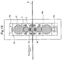
- Fig. 19 is a front view of a six-high rolling mill according to an eighth example of the present invention.
- the eighth example is a six-high rolling mill having side support rolls, where a strip W is rolled by a pair of upper and lower work rolls 2.
- This pair of upper and lower work rolls 2 are supported in contact with a pair of upper and lower intermediate rolls 3, respectively.
- This pair of upper and lower intermediate rolls 3 are supported in contact with a pair of upper and lower back-up rolls 27, respectively.
- This pair of upper and lower back-up rolls 27 are supported by housings 20a and 20b via bearing boxes 39a with a pass line adjuster 18a on the upper side and with a push-up cylinder 19a on the lower side, respectively.
- the eighth example has a configuration where this rolling mill is provided with the first roll shift devices in which the thrust bearings 8a to 8d are effectively installed in the same manner as in the first example.
- the intermediate rolls 3 and the work rolls 2 may be provided with roll benders. These roll benders improve shape controllability, thereby making stable rolling possible.
- the present invention is applicable to a rolling mill having small-diameter work rolls so that edge drop reduction and shape stability are achieved by shifting work rolls having tapered portions in roll axial directions.
Landscapes
- Engineering & Computer Science (AREA)
- Mechanical Engineering (AREA)
- Reduction Rolling/Reduction Stand/Operation Of Reduction Machine (AREA)
- Control Of Metal Rolling (AREA)
- Rolling Contact Bearings (AREA)
Claims (7)
- Laminoir à hauteurs multiples équipé d'une fonction de décalage de cylindres de travail, comprenant une paire de cylindres de travail supérieur et inférieur (2a, 2b) pour laminer une tôle métallique (W), et un ou une pluralité de cylindres de soutien supérieurs et un ou une pluralité de cylindres de soutien inférieurs (3a, 3b, 4a, 4b) soutenant les cylindres de travail (2a, 2b), dans lequel :la paire de cylindres de travail supérieur et inférieur (2a, 2b) est munie de parties effilées (22a, 22b) dans des positions supérieure et inférieure selon un point de symétrie,des faces d'extrémité des cylindres de travail (2a, 2b) sont supportées par deux paliers de poussée supérieurs et deux paliers de poussée inférieurs (8a à 8d) sur un côté de fonctionnement et un côté d'entraînement,des premiers dispositifs de décalage de cylindres (13 à 13d, 11a à 11d) reliés à des boîtes de palier respectives (10a à 10d) pour décaler les cylindres de travail correspondants (2a, 2b) dans les directions axiales des cylindres sont disposés, etdes positions de début d'effilement (SP) des parties effilées (22a, 22b) des cylindres de travail respectifs (2a, 2b) sont décalées vers des voisinages d'intérieurs d'extrémités dans le sens de la largeur de tôle ou des voisinages d'extérieurs d'extrémités dans le sens de la largeur de tôle,caractérisé en ce que :des trous longs (38a à 38d) sont formés dans des arbres latéraux de piste interne (37a à 37d) des boîtes de palier (10a à 10d) supportant en pivotement les paliers de poussés respectifs (8a à 8d), les trous longs (38a à 38d) permettant aux paliers de poussée (8a à 8d) d'être mobiles de façon individuelle avec les boîtes de palier respectives (10a à 10d) dans des directions axiales des cylindres,des barres de couplage (9a, 9b) pénétrant dans les trous longs correspondants (38a à 38d) de façon à restreindre des déplacements verticaux des deux paliers de poussée supérieurs et des deux paliers de poussée inférieurs (8a à 8d) sont disposées entre les boîtes de palier correspondantes (10a à 10d).
- Laminoir à hauteurs multiples équipé d'une fonction de décalage de cylindres de travail selon la revendication 1, caractérisé en ce qu'un rapport D/B (D : diamètre externe de palier, B : largeur de palier) d'un diamètre externe des paliers de poussée (8a à 8d) à une largeur des paliers de poussée (8a à 8d) est établi dans une plage entre 5,0 et 12.
- Laminoir à hauteurs multiples équipé d'une fonction de décalage de cylindres de travail selon la revendication 1 ou 2, caractérisé en ce que des guides (16a à 16d) sont disposés pour guider les boîtes de palier respectives (10a à 10d), sur le côté opposé aux paliers de poussée (8a à 8d), de façon à pouvoir coulisser dans les directions axiales des cylindres et de façon collective, tout en restreignant les boîtes de palier respectives (10a à 10d) dans des directions verticales, de côté d'entrée et de côté de délivrance.
- Laminoir à hauteurs multiples équipé d'une fonction de décalage de cylindres de travail selon la revendication 1, 2 ou 3, caractérisé en ce que chacun des premiers dispositifs de décalage de cylindres comprend : un bras (13a à 13d) réuni au niveau d'une partie médiane de celui-ci à la boîte de palier correspondante (10a à 10d) par l'intermédiaire d'une broche (14a à 14d) ; et un cylindre de décalage (11a à 11d) pour appliquer une force de décalage à une extrémité du bras (13a à 13d) à l'aide d'une articulation (15a à 15d) couplée à l'autre extrémité du bras (13a à 13d) jouant le rôle de point d'appui.
- Laminoir à hauteurs multiples équipé d'une fonction de décalage de cylindres de travail selon l'une quelconque des revendications 1 à 4, caractérisé en ce qu'un détecteur de position (35) de l'extrémité de tôle dans le sens de la largeur pour une tôle métallique est disposé sur un côté d'entrée ou un côté de délivrance du laminoir, et en ce que des moyens de commande (40) pour effectuer des commandes de décalage des premiers dispositifs de décalage de cylindres sont disposés de façon à faire coïncider les positions de début d'effilement (SP) des parties effilées (22a, 22b) des cylindres de travail supérieur et inférieur (2a, 2b) avec les voisinages des intérieurs des extrémités dans le sens de la largueur de tôle ou les voisinages des extérieurs des extrémités dans le sens de la largueur de tôle détectées par le détecteur de position (35) de l'extrémité de tôle dans le sens de la largeur de façon indépendante pour le côté supérieur et le côté inférieur.
- Laminoir à hauteurs multiples équipé d'une fonction de décalage de cylindres de travail selon l'une quelconque des revendications 1 à 5, caractérisé en ce qu'un dispositif de mesure (36) d'épaisseur d'extrémité dans le sens de la largeur de tôle pour mesurer des épaisseurs des extrémités dans le sens de la largeur de tôle d'une tôle métallique est disposé sur un côté de délivrance du laminoir, et en ce que des moyens de commande (41) pour effectuer des commandes de décalage des premiers dispositifs de décalage de cylindres sont disposés de façon à ajuster les positions de début d'effilement (SP) des parties effilées (22a, 22b) des cylindres de travail supérieur et inférieur (2a, 2b) dans les voisinages des intérieurs des extrémités dans le sens de la largeur de tôle de façon individuelle pour le côté supérieur et le côté inférieur, de telle sorte que les épaisseurs des extrémités dans le sens de la largeur de tôle, mesurées sur le côté de fonctionnement et sur le côté d'entraînement, deviennent des épaisseurs prédéterminées.
- Laminoir à hauteurs multiples équipé d'une fonction de décalage de cylindres de travail selon la revendication 5 ou 6, caractérisé en ce que des deuxièmes dispositifs de décalage de cylindres sont de plus disposés pour décaler le cylindre ou la pluralité de cylindres de soutien supérieurs et le cylindre ou la pluralité de cylindres de soutien inférieurs (3a, 3b, 4a, 4b) dans les directions axiales des cylindres, et en ce que les moyens de commande (40) effectuent des commandes de décalage des deuxièmes dispositifs de décalage de cylindres de façon à commander le décalage du cylindre ou de la pluralité de cylindres de soutien supérieurs et du cylindre ou de la pluralité de cylindres de soutien inférieurs (3a, 3b, 4a, 4b) de façon asymétrique sur le côté de fonctionnement et sur le côté d'entraînement.
Applications Claiming Priority (1)
| Application Number | Priority Date | Filing Date | Title |
|---|---|---|---|
| JP2012099721A JP5894849B2 (ja) | 2012-04-25 | 2012-04-25 | 作業ロールシフト機能を具備した多段圧延機 |
Publications (2)
| Publication Number | Publication Date |
|---|---|
| EP2656934A1 EP2656934A1 (fr) | 2013-10-30 |
| EP2656934B1 true EP2656934B1 (fr) | 2016-03-23 |
Family
ID=48193072
Family Applications (1)
| Application Number | Title | Priority Date | Filing Date |
|---|---|---|---|
| EP13002094.4A Active EP2656934B1 (fr) | 2012-04-25 | 2013-04-22 | Train de laminoir multiple élevé équipé d'une fonction de cylindres de travail |
Country Status (4)
| Country | Link |
|---|---|
| EP (1) | EP2656934B1 (fr) |
| JP (1) | JP5894849B2 (fr) |
| CN (1) | CN103372574B (fr) |
| IN (1) | IN2013MU01483A (fr) |
Families Citing this family (7)
| Publication number | Priority date | Publication date | Assignee | Title |
|---|---|---|---|---|
| CN104998914A (zh) * | 2015-07-24 | 2015-10-28 | 中冶南方工程技术有限公司 | 适用于腐蚀环境的压辊装置 |
| CN205659983U (zh) * | 2016-06-15 | 2016-10-26 | 日照宝华新材料有限公司 | 一种esp生产线用长公里数轧制辊 |
| CN108015110B (zh) * | 2017-12-27 | 2024-04-09 | 中重科技(天津)股份有限公司 | 二十辊轧机中间辊系轴向定位装置 |
| CN109807173A (zh) * | 2019-02-27 | 2019-05-28 | 合肥永淇智材科技有限公司 | 一种fmm用金属薄板的减薄装置及其减薄的控制方法 |
| WO2021149747A1 (fr) * | 2020-01-22 | 2021-07-29 | 日本センヂミア株式会社 | Laminoir à étages multiples |
| JP7196341B2 (ja) * | 2020-01-29 | 2022-12-26 | Primetals Technologies Japan株式会社 | 圧延機及び金属板の圧延方法 |
| CN112589155B (zh) * | 2020-11-26 | 2021-09-07 | 广州众山精密科技有限公司 | 一种双辊轧机侧顶装置 |
Family Cites Families (8)
| Publication number | Priority date | Publication date | Assignee | Title |
|---|---|---|---|---|
| JPS5961511A (ja) * | 1982-09-30 | 1984-04-07 | Ishikawajima Harima Heavy Ind Co Ltd | 圧延制御装置 |
| DE3603693A1 (de) * | 1986-02-06 | 1987-08-13 | Schloemann Siemag Ag | Vorrichtung zum axialen verschieben der arbeitswalzen eines walzgeruestes zum walzen von flachmaterial |
| JP2000197903A (ja) * | 1998-12-25 | 2000-07-18 | Sumitomo Metal Ind Ltd | 鋼板圧延方法、鋼板圧延用ロ―ルおよび鋼板用圧延機 |
| CN1184024C (zh) * | 2000-03-27 | 2005-01-12 | 三菱重工业株式会社 | 多辊轧机工作轧辊移位装置和方法 |
| JP3640162B2 (ja) * | 2000-09-22 | 2005-04-20 | Jfeスチール株式会社 | クラスター型圧延機における高光沢金属帯の冷間圧延方法 |
| JP3747786B2 (ja) * | 2001-02-05 | 2006-02-22 | 株式会社日立製作所 | 板材用圧延機の圧延方法及び板材用圧延設備 |
| DE102008045359B3 (de) | 2008-08-22 | 2010-05-20 | Deutsches Elektronen-Synchrotron Desy | Detektion von Veränderungen eines Zeitabstands optischer oder elektrischer Signale |
| JP5683082B2 (ja) * | 2009-07-29 | 2015-03-11 | 三菱日立製鉄機械株式会社 | 作業ロールシフト機能を具備した圧延機 |
-
2012
- 2012-04-25 JP JP2012099721A patent/JP5894849B2/ja active Active
-
2013
- 2013-04-17 CN CN201310133761.XA patent/CN103372574B/zh active Active
- 2013-04-22 EP EP13002094.4A patent/EP2656934B1/fr active Active
- 2013-04-23 IN IN1483MU2013 patent/IN2013MU01483A/en unknown
Also Published As
| Publication number | Publication date |
|---|---|
| IN2013MU01483A (fr) | 2015-04-17 |
| JP5894849B2 (ja) | 2016-03-30 |
| CN103372574B (zh) | 2015-06-17 |
| EP2656934A1 (fr) | 2013-10-30 |
| CN103372574A (zh) | 2013-10-30 |
| JP2013226572A (ja) | 2013-11-07 |
Similar Documents
| Publication | Publication Date | Title |
|---|---|---|
| EP2656934B1 (fr) | Train de laminoir multiple élevé équipé d'une fonction de cylindres de travail | |
| EP2489447B1 (fr) | Laminoir et procédé de réglage du zéro dans un laminoir | |
| EP2248609B1 (fr) | Laminoir à grosses tôles et procédé de laminage de tôles fortes | |
| JP5491090B2 (ja) | 圧延機及びそれを備えたタンデム圧延機 | |
| CN101918153B (zh) | 轧机和具有这种轧机的串列式轧机 | |
| EP2656933B1 (fr) | Laminoir doté d'une fonction de commutation de cylindre de travail | |
| EP2260954B2 (fr) | Laminoir de tôle forte et procédé de laminage de tôle forte | |
| JP2020040097A (ja) | 圧延機及び圧延機の設定方法 | |
| JP2006181639A (ja) | 金属材の圧延機及び圧延方法 | |
| US8794045B2 (en) | Cluster-type multistage rolling mill | |
| JP5711232B2 (ja) | 作業ロール径の設定方法 | |
| JP2011045933A (ja) | 金属材の圧延機及び圧延方法 | |
| JP5929048B2 (ja) | 熱間圧延方法 | |
| KR102252361B1 (ko) | 크로스각 동정 방법, 크로스각 동정 장치, 및 압연기 | |
| JP5568261B2 (ja) | 圧延機及びそれを備えたタンデム圧延機 | |
| KR102390362B1 (ko) | 압연기 및 압연기의 설정 방법 | |
| KR102386637B1 (ko) | 압연기의 설정 방법 및 압연기 |
Legal Events
| Date | Code | Title | Description |
|---|---|---|---|
| PUAI | Public reference made under article 153(3) epc to a published international application that has entered the european phase |
Free format text: ORIGINAL CODE: 0009012 |
|
| 17P | Request for examination filed |
Effective date: 20130828 |
|
| AK | Designated contracting states |
Kind code of ref document: A1 Designated state(s): AL AT BE BG CH CY CZ DE DK EE ES FI FR GB GR HR HU IE IS IT LI LT LU LV MC MK MT NL NO PL PT RO RS SE SI SK SM TR |
|
| AX | Request for extension of the european patent |
Extension state: BA ME |
|
| RBV | Designated contracting states (corrected) |
Designated state(s): AL AT BE BG CH CY CZ DE DK EE ES FI FR GB GR HR HU IE IS IT LI LT LU LV MC MK MT NL NO PL PT RO RS SE SI SK SM TR |
|
| RIC1 | Information provided on ipc code assigned before grant |
Ipc: B21B 13/14 20060101AFI20150720BHEP |
|
| GRAP | Despatch of communication of intention to grant a patent |
Free format text: ORIGINAL CODE: EPIDOSNIGR1 |
|
| INTG | Intention to grant announced |
Effective date: 20150910 |
|
| RAP1 | Party data changed (applicant data changed or rights of an application transferred) |
Owner name: PRIMETALS TECHNOLOGIES JAPAN, LTD. |
|
| GRAS | Grant fee paid |
Free format text: ORIGINAL CODE: EPIDOSNIGR3 |
|
| GRAA | (expected) grant |
Free format text: ORIGINAL CODE: 0009210 |
|
| AK | Designated contracting states |
Kind code of ref document: B1 Designated state(s): AL AT BE BG CH CY CZ DE DK EE ES FI FR GB GR HR HU IE IS IT LI LT LU LV MC MK MT NL NO PL PT RO RS SE SI SK SM TR |
|
| REG | Reference to a national code |
Ref country code: GB Ref legal event code: FG4D |
|
| REG | Reference to a national code |
Ref country code: CH Ref legal event code: EP |
|
| REG | Reference to a national code |
Ref country code: FR Ref legal event code: PLFP Year of fee payment: 4 |
|
| REG | Reference to a national code |
Ref country code: AT Ref legal event code: REF Ref document number: 782603 Country of ref document: AT Kind code of ref document: T Effective date: 20160415 |
|
| REG | Reference to a national code |
Ref country code: IE Ref legal event code: FG4D |
|
| REG | Reference to a national code |
Ref country code: DE Ref legal event code: R096 Ref document number: 602013005607 Country of ref document: DE |
|
| REG | Reference to a national code |
Ref country code: LT Ref legal event code: MG4D |
|
| REG | Reference to a national code |
Ref country code: NL Ref legal event code: MP Effective date: 20160323 |
|
| PG25 | Lapsed in a contracting state [announced via postgrant information from national office to epo] |
Ref country code: GR Free format text: LAPSE BECAUSE OF FAILURE TO SUBMIT A TRANSLATION OF THE DESCRIPTION OR TO PAY THE FEE WITHIN THE PRESCRIBED TIME-LIMIT Effective date: 20160624 Ref country code: NO Free format text: LAPSE BECAUSE OF FAILURE TO SUBMIT A TRANSLATION OF THE DESCRIPTION OR TO PAY THE FEE WITHIN THE PRESCRIBED TIME-LIMIT Effective date: 20160623 Ref country code: HR Free format text: LAPSE BECAUSE OF FAILURE TO SUBMIT A TRANSLATION OF THE DESCRIPTION OR TO PAY THE FEE WITHIN THE PRESCRIBED TIME-LIMIT Effective date: 20160323 Ref country code: FI Free format text: LAPSE BECAUSE OF FAILURE TO SUBMIT A TRANSLATION OF THE DESCRIPTION OR TO PAY THE FEE WITHIN THE PRESCRIBED TIME-LIMIT Effective date: 20160323 |
|
| REG | Reference to a national code |
Ref country code: AT Ref legal event code: MK05 Ref document number: 782603 Country of ref document: AT Kind code of ref document: T Effective date: 20160323 |
|
| PG25 | Lapsed in a contracting state [announced via postgrant information from national office to epo] |
Ref country code: SE Free format text: LAPSE BECAUSE OF FAILURE TO SUBMIT A TRANSLATION OF THE DESCRIPTION OR TO PAY THE FEE WITHIN THE PRESCRIBED TIME-LIMIT Effective date: 20160323 Ref country code: BE Free format text: LAPSE BECAUSE OF NON-PAYMENT OF DUE FEES Effective date: 20160430 Ref country code: LT Free format text: LAPSE BECAUSE OF FAILURE TO SUBMIT A TRANSLATION OF THE DESCRIPTION OR TO PAY THE FEE WITHIN THE PRESCRIBED TIME-LIMIT Effective date: 20160323 Ref country code: RS Free format text: LAPSE BECAUSE OF FAILURE TO SUBMIT A TRANSLATION OF THE DESCRIPTION OR TO PAY THE FEE WITHIN THE PRESCRIBED TIME-LIMIT Effective date: 20160323 Ref country code: LV Free format text: LAPSE BECAUSE OF FAILURE TO SUBMIT A TRANSLATION OF THE DESCRIPTION OR TO PAY THE FEE WITHIN THE PRESCRIBED TIME-LIMIT Effective date: 20160323 Ref country code: NL Free format text: LAPSE BECAUSE OF FAILURE TO SUBMIT A TRANSLATION OF THE DESCRIPTION OR TO PAY THE FEE WITHIN THE PRESCRIBED TIME-LIMIT Effective date: 20160323 |
|
| PG25 | Lapsed in a contracting state [announced via postgrant information from national office to epo] |
Ref country code: PL Free format text: LAPSE BECAUSE OF FAILURE TO SUBMIT A TRANSLATION OF THE DESCRIPTION OR TO PAY THE FEE WITHIN THE PRESCRIBED TIME-LIMIT Effective date: 20160323 Ref country code: IS Free format text: LAPSE BECAUSE OF FAILURE TO SUBMIT A TRANSLATION OF THE DESCRIPTION OR TO PAY THE FEE WITHIN THE PRESCRIBED TIME-LIMIT Effective date: 20160723 Ref country code: EE Free format text: LAPSE BECAUSE OF FAILURE TO SUBMIT A TRANSLATION OF THE DESCRIPTION OR TO PAY THE FEE WITHIN THE PRESCRIBED TIME-LIMIT Effective date: 20160323 |
|
| PG25 | Lapsed in a contracting state [announced via postgrant information from national office to epo] |
Ref country code: ES Free format text: LAPSE BECAUSE OF FAILURE TO SUBMIT A TRANSLATION OF THE DESCRIPTION OR TO PAY THE FEE WITHIN THE PRESCRIBED TIME-LIMIT Effective date: 20160323 Ref country code: SM Free format text: LAPSE BECAUSE OF FAILURE TO SUBMIT A TRANSLATION OF THE DESCRIPTION OR TO PAY THE FEE WITHIN THE PRESCRIBED TIME-LIMIT Effective date: 20160323 Ref country code: CZ Free format text: LAPSE BECAUSE OF FAILURE TO SUBMIT A TRANSLATION OF THE DESCRIPTION OR TO PAY THE FEE WITHIN THE PRESCRIBED TIME-LIMIT Effective date: 20160323 Ref country code: PT Free format text: LAPSE BECAUSE OF FAILURE TO SUBMIT A TRANSLATION OF THE DESCRIPTION OR TO PAY THE FEE WITHIN THE PRESCRIBED TIME-LIMIT Effective date: 20160725 Ref country code: RO Free format text: LAPSE BECAUSE OF FAILURE TO SUBMIT A TRANSLATION OF THE DESCRIPTION OR TO PAY THE FEE WITHIN THE PRESCRIBED TIME-LIMIT Effective date: 20160323 Ref country code: AT Free format text: LAPSE BECAUSE OF FAILURE TO SUBMIT A TRANSLATION OF THE DESCRIPTION OR TO PAY THE FEE WITHIN THE PRESCRIBED TIME-LIMIT Effective date: 20160323 Ref country code: SK Free format text: LAPSE BECAUSE OF FAILURE TO SUBMIT A TRANSLATION OF THE DESCRIPTION OR TO PAY THE FEE WITHIN THE PRESCRIBED TIME-LIMIT Effective date: 20160323 |
|
| REG | Reference to a national code |
Ref country code: CH Ref legal event code: PL |
|
| PG25 | Lapsed in a contracting state [announced via postgrant information from national office to epo] |
Ref country code: BE Free format text: LAPSE BECAUSE OF FAILURE TO SUBMIT A TRANSLATION OF THE DESCRIPTION OR TO PAY THE FEE WITHIN THE PRESCRIBED TIME-LIMIT Effective date: 20160323 Ref country code: IT Free format text: LAPSE BECAUSE OF FAILURE TO SUBMIT A TRANSLATION OF THE DESCRIPTION OR TO PAY THE FEE WITHIN THE PRESCRIBED TIME-LIMIT Effective date: 20160323 |
|
| REG | Reference to a national code |
Ref country code: DE Ref legal event code: R097 Ref document number: 602013005607 Country of ref document: DE |
|
| REG | Reference to a national code |
Ref country code: IE Ref legal event code: MM4A |
|
| PLBE | No opposition filed within time limit |
Free format text: ORIGINAL CODE: 0009261 |
|
| STAA | Information on the status of an ep patent application or granted ep patent |
Free format text: STATUS: NO OPPOSITION FILED WITHIN TIME LIMIT |
|
| PG25 | Lapsed in a contracting state [announced via postgrant information from national office to epo] |
Ref country code: DK Free format text: LAPSE BECAUSE OF FAILURE TO SUBMIT A TRANSLATION OF THE DESCRIPTION OR TO PAY THE FEE WITHIN THE PRESCRIBED TIME-LIMIT Effective date: 20160323 Ref country code: LI Free format text: LAPSE BECAUSE OF NON-PAYMENT OF DUE FEES Effective date: 20160430 Ref country code: CH Free format text: LAPSE BECAUSE OF NON-PAYMENT OF DUE FEES Effective date: 20160430 |
|
| PG25 | Lapsed in a contracting state [announced via postgrant information from national office to epo] |
Ref country code: BG Free format text: LAPSE BECAUSE OF FAILURE TO SUBMIT A TRANSLATION OF THE DESCRIPTION OR TO PAY THE FEE WITHIN THE PRESCRIBED TIME-LIMIT Effective date: 20160623 |
|
| 26N | No opposition filed |
Effective date: 20170102 |
|
| REG | Reference to a national code |
Ref country code: FR Ref legal event code: PLFP Year of fee payment: 5 |
|
| PG25 | Lapsed in a contracting state [announced via postgrant information from national office to epo] |
Ref country code: IE Free format text: LAPSE BECAUSE OF NON-PAYMENT OF DUE FEES Effective date: 20160422 Ref country code: SI Free format text: LAPSE BECAUSE OF FAILURE TO SUBMIT A TRANSLATION OF THE DESCRIPTION OR TO PAY THE FEE WITHIN THE PRESCRIBED TIME-LIMIT Effective date: 20160323 |
|
| GBPC | Gb: european patent ceased through non-payment of renewal fee |
Effective date: 20170422 |
|
| PG25 | Lapsed in a contracting state [announced via postgrant information from national office to epo] |
Ref country code: GB Free format text: LAPSE BECAUSE OF NON-PAYMENT OF DUE FEES Effective date: 20170422 |
|
| REG | Reference to a national code |
Ref country code: FR Ref legal event code: PLFP Year of fee payment: 6 |
|
| PG25 | Lapsed in a contracting state [announced via postgrant information from national office to epo] |
Ref country code: CY Free format text: LAPSE BECAUSE OF FAILURE TO SUBMIT A TRANSLATION OF THE DESCRIPTION OR TO PAY THE FEE WITHIN THE PRESCRIBED TIME-LIMIT Effective date: 20160323 Ref country code: HU Free format text: LAPSE BECAUSE OF FAILURE TO SUBMIT A TRANSLATION OF THE DESCRIPTION OR TO PAY THE FEE WITHIN THE PRESCRIBED TIME-LIMIT; INVALID AB INITIO Effective date: 20130422 |
|
| PG25 | Lapsed in a contracting state [announced via postgrant information from national office to epo] |
Ref country code: LU Free format text: LAPSE BECAUSE OF NON-PAYMENT OF DUE FEES Effective date: 20160422 Ref country code: TR Free format text: LAPSE BECAUSE OF FAILURE TO SUBMIT A TRANSLATION OF THE DESCRIPTION OR TO PAY THE FEE WITHIN THE PRESCRIBED TIME-LIMIT Effective date: 20160323 Ref country code: MT Free format text: LAPSE BECAUSE OF NON-PAYMENT OF DUE FEES Effective date: 20160430 Ref country code: MK Free format text: LAPSE BECAUSE OF FAILURE TO SUBMIT A TRANSLATION OF THE DESCRIPTION OR TO PAY THE FEE WITHIN THE PRESCRIBED TIME-LIMIT Effective date: 20160323 Ref country code: MC Free format text: LAPSE BECAUSE OF FAILURE TO SUBMIT A TRANSLATION OF THE DESCRIPTION OR TO PAY THE FEE WITHIN THE PRESCRIBED TIME-LIMIT Effective date: 20160323 |
|
| PG25 | Lapsed in a contracting state [announced via postgrant information from national office to epo] |
Ref country code: AL Free format text: LAPSE BECAUSE OF FAILURE TO SUBMIT A TRANSLATION OF THE DESCRIPTION OR TO PAY THE FEE WITHIN THE PRESCRIBED TIME-LIMIT Effective date: 20160323 |
|
| PGFP | Annual fee paid to national office [announced via postgrant information from national office to epo] |
Ref country code: FR Payment date: 20240308 Year of fee payment: 12 |
|
| PGFP | Annual fee paid to national office [announced via postgrant information from national office to epo] |
Ref country code: DE Payment date: 20240227 Year of fee payment: 12 |