EP2655766B1 - Reinforced motor vehicle lock - Google Patents
Reinforced motor vehicle lock Download PDFInfo
- Publication number
- EP2655766B1 EP2655766B1 EP11817210.5A EP11817210A EP2655766B1 EP 2655766 B1 EP2655766 B1 EP 2655766B1 EP 11817210 A EP11817210 A EP 11817210A EP 2655766 B1 EP2655766 B1 EP 2655766B1
- Authority
- EP
- European Patent Office
- Prior art keywords
- lock
- reinforcing insert
- reinforcing
- case
- lock case
- Prior art date
- Legal status (The legal status is an assumption and is not a legal conclusion. Google has not performed a legal analysis and makes no representation as to the accuracy of the status listed.)
- Active
Links
- 230000003014 reinforcing effect Effects 0.000 claims description 63
- 239000002184 metal Substances 0.000 claims description 6
- 230000002787 reinforcement Effects 0.000 description 9
- 229910000831 Steel Inorganic materials 0.000 description 5
- 239000010959 steel Substances 0.000 description 5
- 238000005553 drilling Methods 0.000 description 2
- 238000004519 manufacturing process Methods 0.000 description 2
- 239000002699 waste material Substances 0.000 description 2
- 238000005452 bending Methods 0.000 description 1
- 230000000903 blocking effect Effects 0.000 description 1
- 238000005520 cutting process Methods 0.000 description 1
- 239000000428 dust Substances 0.000 description 1
- 230000000694 effects Effects 0.000 description 1
- 238000003801 milling Methods 0.000 description 1
- 238000004080 punching Methods 0.000 description 1
- 238000003860 storage Methods 0.000 description 1
- 239000013589 supplement Substances 0.000 description 1
- XLYOFNOQVPJJNP-UHFFFAOYSA-N water Substances O XLYOFNOQVPJJNP-UHFFFAOYSA-N 0.000 description 1
Images

Classifications
-
- E—FIXED CONSTRUCTIONS
- E05—LOCKS; KEYS; WINDOW OR DOOR FITTINGS; SAFES
- E05B—LOCKS; ACCESSORIES THEREFOR; HANDCUFFS
- E05B85/00—Details of vehicle locks not provided for in groups E05B77/00 - E05B83/00
- E05B85/20—Bolts or detents
-
- E—FIXED CONSTRUCTIONS
- E05—LOCKS; KEYS; WINDOW OR DOOR FITTINGS; SAFES
- E05B—LOCKS; ACCESSORIES THEREFOR; HANDCUFFS
- E05B53/00—Operation or control of locks by mechanical transmissions, e.g. from a distance
-
- E—FIXED CONSTRUCTIONS
- E05—LOCKS; KEYS; WINDOW OR DOOR FITTINGS; SAFES
- E05B—LOCKS; ACCESSORIES THEREFOR; HANDCUFFS
- E05B77/00—Vehicle locks characterised by special functions or purposes
- E05B77/02—Vehicle locks characterised by special functions or purposes for accident situations
- E05B77/10—Allowing opening in case of deformed bodywork, e.g. by preventing deformation of lock parts
-
- E—FIXED CONSTRUCTIONS
- E05—LOCKS; KEYS; WINDOW OR DOOR FITTINGS; SAFES
- E05B—LOCKS; ACCESSORIES THEREFOR; HANDCUFFS
- E05B79/00—Mounting or connecting vehicle locks or parts thereof
- E05B79/02—Mounting of vehicle locks or parts thereof
- E05B79/08—Mounting of individual lock elements in the lock, e.g. levers
-
- E—FIXED CONSTRUCTIONS
- E05—LOCKS; KEYS; WINDOW OR DOOR FITTINGS; SAFES
- E05B—LOCKS; ACCESSORIES THEREFOR; HANDCUFFS
- E05B79/00—Mounting or connecting vehicle locks or parts thereof
- E05B79/10—Connections between movable lock parts
- E05B79/20—Connections between movable lock parts using flexible connections, e.g. Bowden cables
-
- E—FIXED CONSTRUCTIONS
- E05—LOCKS; KEYS; WINDOW OR DOOR FITTINGS; SAFES
- E05B—LOCKS; ACCESSORIES THEREFOR; HANDCUFFS
- E05B85/00—Details of vehicle locks not provided for in groups E05B77/00 - E05B83/00
- E05B85/02—Lock casings
-
- E—FIXED CONSTRUCTIONS
- E05—LOCKS; KEYS; WINDOW OR DOOR FITTINGS; SAFES
- E05B—LOCKS; ACCESSORIES THEREFOR; HANDCUFFS
- E05B79/00—Mounting or connecting vehicle locks or parts thereof
- E05B79/02—Mounting of vehicle locks or parts thereof
-
- E—FIXED CONSTRUCTIONS
- E05—LOCKS; KEYS; WINDOW OR DOOR FITTINGS; SAFES
- E05B—LOCKS; ACCESSORIES THEREFOR; HANDCUFFS
- E05B79/00—Mounting or connecting vehicle locks or parts thereof
- E05B79/02—Mounting of vehicle locks or parts thereof
- E05B79/04—Mounting of lock casings to the vehicle, e.g. to the wing
-
- E—FIXED CONSTRUCTIONS
- E05—LOCKS; KEYS; WINDOW OR DOOR FITTINGS; SAFES
- E05B—LOCKS; ACCESSORIES THEREFOR; HANDCUFFS
- E05B79/00—Mounting or connecting vehicle locks or parts thereof
- E05B79/02—Mounting of vehicle locks or parts thereof
- E05B79/06—Mounting of handles, e.g. to the wing or to the lock
-
- Y—GENERAL TAGGING OF NEW TECHNOLOGICAL DEVELOPMENTS; GENERAL TAGGING OF CROSS-SECTIONAL TECHNOLOGIES SPANNING OVER SEVERAL SECTIONS OF THE IPC; TECHNICAL SUBJECTS COVERED BY FORMER USPC CROSS-REFERENCE ART COLLECTIONS [XRACs] AND DIGESTS
- Y10—TECHNICAL SUBJECTS COVERED BY FORMER USPC
- Y10T—TECHNICAL SUBJECTS COVERED BY FORMER US CLASSIFICATION
- Y10T292/00—Closure fasteners
- Y10T292/08—Bolts
- Y10T292/1043—Swinging
- Y10T292/1044—Multiple head
- Y10T292/1045—Operating means
- Y10T292/1046—Cam
-
- Y—GENERAL TAGGING OF NEW TECHNOLOGICAL DEVELOPMENTS; GENERAL TAGGING OF CROSS-SECTIONAL TECHNOLOGIES SPANNING OVER SEVERAL SECTIONS OF THE IPC; TECHNICAL SUBJECTS COVERED BY FORMER USPC CROSS-REFERENCE ART COLLECTIONS [XRACs] AND DIGESTS
- Y10—TECHNICAL SUBJECTS COVERED BY FORMER USPC
- Y10T—TECHNICAL SUBJECTS COVERED BY FORMER US CLASSIFICATION
- Y10T292/00—Closure fasteners
- Y10T292/08—Bolts
- Y10T292/1043—Swinging
- Y10T292/1044—Multiple head
- Y10T292/1045—Operating means
- Y10T292/1047—Closure
-
- Y—GENERAL TAGGING OF NEW TECHNOLOGICAL DEVELOPMENTS; GENERAL TAGGING OF CROSS-SECTIONAL TECHNOLOGIES SPANNING OVER SEVERAL SECTIONS OF THE IPC; TECHNICAL SUBJECTS COVERED BY FORMER USPC CROSS-REFERENCE ART COLLECTIONS [XRACs] AND DIGESTS
- Y10—TECHNICAL SUBJECTS COVERED BY FORMER USPC
- Y10T—TECHNICAL SUBJECTS COVERED BY FORMER US CLASSIFICATION
- Y10T292/00—Closure fasteners
- Y10T292/08—Bolts
- Y10T292/1043—Swinging
- Y10T292/1075—Operating means
- Y10T292/108—Lever
-
- Y—GENERAL TAGGING OF NEW TECHNOLOGICAL DEVELOPMENTS; GENERAL TAGGING OF CROSS-SECTIONAL TECHNOLOGIES SPANNING OVER SEVERAL SECTIONS OF THE IPC; TECHNICAL SUBJECTS COVERED BY FORMER USPC CROSS-REFERENCE ART COLLECTIONS [XRACs] AND DIGESTS
- Y10—TECHNICAL SUBJECTS COVERED BY FORMER USPC
- Y10T—TECHNICAL SUBJECTS COVERED BY FORMER US CLASSIFICATION
- Y10T292/00—Closure fasteners
- Y10T292/08—Bolts
- Y10T292/1043—Swinging
- Y10T292/1075—Operating means
- Y10T292/1082—Motor
Definitions
- the present invention relates to a lock, in particular a motor vehicle lock with a lock housing, a lock case, a locking mechanism and an actuating device, wherein at least one component of the actuating device extends through an opening in the lock housing and this opening is formed with at least one reinforcing insert.
- a motor vehicle lock serves to close motor vehicle doors, flaps and the like.
- a motor vehicle lock comprises a locking mechanism with a catch and a pawl for locking.
- the catch and the pawl are arranged so that they can receive and lock a body-mounted lock holder in the locked position.
- the pawl has the task of locking the catch in this position.
- Rotary latch and pawl are usually rotatably mounted on a basically metal lock case.
- the lock case often performs other functions and can serve, for example, the attachment of the lock in a vehicle door or vehicle door.
- other components or components may be attached to the lock case such as a rotatably mounted blocking lever, which is able to block the pawl in its locked position.
- a reinforcing plate also basically made of metal, which serves to supplement the rotatable attachment of the catch and / or pawl.
- Rotary latch and pawl are usually located between the lock case and the amplifier plate. Since the reinforcing plate basically only serves the improved attachment of the rotary latch and / or pawl, its base is regularly small compared to the base of the lock box.
- a motor vehicle lock basically comprises a lock housing for covering one or more components of the motor vehicle lock.
- the lock housing is often closed with a lock cover to further improve the desired protection of components.
- the lock housing and the lock cover are preferably made of plastic for weight reasons.
- An actuating device of such a motor vehicle lock is used to open the locking mechanism.
- Such an actuating device may comprise a Bowden cable.
- the Bowden cable soul can be passed through an opening in the lock housing, as the document WO 2009/049588 A2 can be seen.
- a locking mechanism of a motor vehicle can be exposed to increased forces, in particular in the event of a motor vehicle side impact, for example when an outer door panel is pressed against the housing and causes massive deformation here. In the extreme case, this can lead to a blockage of the locking mechanism, so that an associated motor vehicle door can only be opened with great effort. Therefore, it has been proposed to provide reinforcing elements in the motor vehicle lock to improve the crash safety, z. B, in the form of reinforcing plates connected to the housing. In order to further increase operational safety even in the event of a crash, according to the WO 2009/049588 A2 taught to provide the aforementioned opening in the lock housing additionally with a reinforcing insert and that by a suitable extension of the reinforcing plate.
- the publication FR 2 778 198 a motor vehicle lock with a housing, a lock case, a locking mechanism and an actuating device which extends through an opening in the lock housing therethrough.
- the lock also includes a mounting rail which is connected to the lock case.
- the publication WO 2008/104073 A1 discloses another motor vehicle lock having a housing, a lock case, a ratchet and an actuator extending through an opening of the lock.
- a motor vehicle lock comprises the features of claim 1.
- Advantageous embodiments emerge from the subclaims.
- a motor vehicle lock is provided with a lock housing, a lock case, a locking mechanism and an actuating device, wherein at least one component of the actuating device, in particular a core of a Bowden cable extends through an opening in the lock housing.
- This opening is provided with a reinforcing insert to ensure good reliability.
- the reinforcement insert is part of the lock case.
- the lock case according to the invention comprises two side walls, which form a right angle with the base of the lock case.
- the side walls serve u. a. the protection of the locking mechanism attached to the base and, as a rule, the attachment of the lock.
- the side walls extend to the height of the reinforcing insert.
- the reinforcing insert is located between two end portions of the side walls. The side walls thus protect the reinforcing insert from undesired external mechanical effects such as impact loads. The operational safety is further improved.
- the base of the plate or sheet, from which the lock case is machined, is basically relatively large. Against this background, it has proven to be advantageous to form the reinforcement insert from the lock case, so as to minimize a waste during manufacture or even completely avoided. Reinforcement insert and lock case are thus integrally connected.
- the plate or sheet In order to work out this lock case from the base of the plate or the sheet, the plate or sheet is first suitably punched, drilled and / or milled. Subsequently, the punched plate or sheet is suitably bent to provide the lock case with the reinforcing insert. The waste resulting from the punching increases at most slightly by the provision of the reinforcing insert.
- the reinforcing insert is preferably connected via a web to the base of the lock case. Such a connection between base and reinforcement insert has proven to be sufficiently stable. The reinforcing insert together with the bridge then contributes only slightly to the overall weight of the lock case.
- the reinforcing insert is preferably fork-shaped or U-shaped to hang a Bowden cable comfortably.
- the lock case including the reinforcement insert is basically made of metal to provide a mechanically stable base for the lock.
- the lock housing is basically made of plastic to protect against pollution and the like with low weight.
- the reinforcing insert is basically in the lock housing or within a double wall of the lock housing and is in particular connected to the lock housing by a snap connection. Externally, the lock resembles a conventional lock and can therefore be handled in the same way as conventional locks.
- the strength of the lock case is greater than the thickness of a reinforcing plate of the motor vehicle lock.
- the forces occurring during operation can be so useful mainly absorbed by the lock case.
- the opening is advantageously particularly well reinforced and thus achieved a particularly high reliability.
- the lock case is therefore preferably made of a 1.5 mm to 3 mm thick, in particular made of steel plate.
- the reinforcing plate is therefore preferably made of a 0.5 mm to 2 mm thick, in particular made of steel plate.
- the thickness of the lock case is then 1.5 mm to 3 mm, so for example 2 mm and the thickness of the reinforcing plate 0.5 mm to 2 mm, for example, 1.5 mm.
- the reinforcing plate is in particular U-shaped and therefore does not have the from WO 2009/049588 A2 known extension, which serves to reinforce the opening of the lock housing.
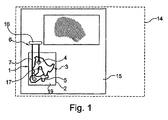
- FIG. 1 schematically illustrates a motor vehicle 14 with a door 15 having a motor vehicle lock 1.
- a motor vehicle lock 1 can be actuated via a door handle 16 on the door 15, wherein an actuation action is transmitted to the locking mechanism 3 via an actuating device 6.
- the actuating device 6 can basically be designed as a lever.
- a Bowden cable 7 is shown.
- the actuating device 6 extends into an interior 19 of the indicated lock housing 2.
- the locking mechanism 3 is arranged, which has a rotary latch 4 and a pawl 5.
- the catch 4 receives a body-side fastened lock holder 17 and is blocked by the locking pawl 5 by latching movement.
- the Bowden cable 7 With the help of the Bowden cable 7, an opening movement of the door handle 16 can be transmitted to the pawl 5, that the pawl is pivoted out of the detent position shown.
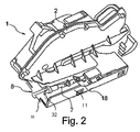
- the Fig. 2 shows a perspective view of an embodiment of a motor vehicle lock 1, in which case the encapsulated lock housing 2 can be seen.
- an indicated opening 8 is provided, in which a Bowden cable 7 is guided or fixed via a bearing 32.
- the opening 8 is inserted in a part of the lock housing 2 made of plastic.
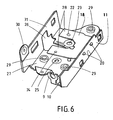
- the bearing 32 is inserted into the U- or omega-shaped opening 8, wherein there provided a reinforcing insert 9 (see, in particular FIG. 6 ) ensures the fixation of the bearing 32 even at high forces.
- the reinforcing insert 9 is in the FIG. 2 not shown for reasons of clarity.
- the ua in the FIG. 6 shown reinforcing insert 9 is about a in the FIG.
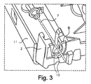
- the Fig. 3 shows in perspective from another viewing direction fragmentary the Bowden cable 7 of the actuator, which is passed through the aforementioned opening of the lock housing 2, which passes through two walls or double wall 12 of the lock housing 2 and a double wall 12 therethrough.
- the Bowden cable soul is moved in the direction of extension back and forth and acted upon by a corresponding force.
- the reinforcing insert 9 is provided in the region of the opening with the adjacent wall regions 12, which essentially forms a same opening or receptacle for the Bowden cable 7.
- the reinforcing insert 9 is located between the two walls 12 of the lock housing 2.
- the reinforcing insert 9 is held by the two walls 12 preferably in latched form.
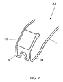
- the reinforcing insert 9 extends downward in the direction of, for example, in FIG FIG. 5 shown web 10 and is integrally connected thereto.
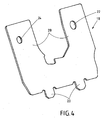
- FIG. 4 A preferred embodiment of a 1, 5 mm thick, preferably made of steel or another metal, U-shaped reinforcing plate 18 is shown with legs 28. Laterally projecting pins 20 serve to hook into a side wall 11 of a lock case 33, so as to avoid a lateral projection of the reinforcing plate.
- a bore 22 in a leg 28 of the U-shape serves to receive the axis of rotation of the rotary latch. The bore preferably has a relatively large diameter, since the diameter of the rotary latch axis is usually relatively large.
- Another bore 24 in the other leg 28 of the U-shape serves to receive the axis of rotation of the pawl.
- the bore 24 preferably has a comparatively small diameter, since the diameter of the pawl axis is usually relatively small.
- a lock case 33 is shown having a base 27 with the side wall 11.
- the bore 23 in the base 27 has a relatively large diameter and serves for the rotatable mounting of the rotary latch axis.
- a bore 30 in a further side wall 31 of the lock case 13 can serve for fastening the motor vehicle lock to a door or flap or for other fastening purposes.
- a web 10 connects the base 27 with the reinforcing insert 9.
- the side wall 11 has an elevation 34, which, viewed from the base 27, is just as high as the reinforcing insert 9. This end region with the elevation 34 has such a course that this the course of web 10 and reinforcing insert 9 is equal.
- the reinforcing insert 9 is thus protected by the side wall 11, and in particular by the region of the side wall with the elevation 34.
- the reinforcing insert 9 is located between two end regions of the two side walls 11 and 31.
- the reinforcing insert 9 is enlarged from a different perspective (shown in the detail of the lock box 33). Based on FIG. 7 It becomes clear how a sheet has to be punched out and bent in order, among other things, to work out the reinforcement insert 9 together with the web 10 from the sheet metal.
Description
Die vorliegende Erfindung betrifft ein Schloss, insbesondere ein Kraftfahrzeugschloss mit einem Schlossgehäuse, einem Schlosskasten, einem Gesperre und einer Betätigungseinrichtung, wobei sich zumindest eine Komponente der Betätigungseinrichtung durch eine Öffnung im Schlossgehäuse hindurch erstreckt und diese Öffnung mit zumindest einem Verstärkungseinsatz ausgebildet ist.The present invention relates to a lock, in particular a motor vehicle lock with a lock housing, a lock case, a locking mechanism and an actuating device, wherein at least one component of the actuating device extends through an opening in the lock housing and this opening is formed with at least one reinforcing insert.
Ein Kraftfahrzeugschloss dient dem Verschließen von Kraftfahrzeugtüren, -klappen und dergleichen. Ein Kraftfahrzeugschloss umfasst für ein Verschließen ein Gesperre mit einer Drehfalle und einer Sperrklinke. Drehfalle und Sperrklinke sind so angeordnet, dass sie einen karosserieseitig befestigten Schlosshalter in der verriegelten Position aufnehmen und arretieren können. Die Sperrklinke hat dabei die Aufgabe, die Drehfalle in dieser Position zu verrasten.A motor vehicle lock serves to close motor vehicle doors, flaps and the like. A motor vehicle lock comprises a locking mechanism with a catch and a pawl for locking. The catch and the pawl are arranged so that they can receive and lock a body-mounted lock holder in the locked position. The pawl has the task of locking the catch in this position.
Drehfalle und Sperrklinke sind in der Regel an einem grundsätzlich aus Metall bestehenden Schlosskasten drehbar befestigt. Der Schlosskasten übernimmt vielfach weitere Funktionen und kann zum Beispiel der Befestigung des Schlosses in einer Fahrzeugtür oder Fahrzeugklappe dienen. Außerdem können an dem Schlosskasten weitere Komponenten oder Bauteile befestigt sein wie zum Beispiel ein drehbar befestigter Blockadehebel, der die Sperrklinke in ihrer Raststellung zu blockieren vermag. Üblicherweise gibt es ferner eine ebenfalls grundsätzlich aus Metall bestehende Verstärkungsplatte, die der ergänzenden drehbaren Befestigung der Drehfalle und/ oder Sperrklinke dient. Drehfalle sowie Sperrklinke befinden sich in der Regel zwischen dem Schlosskasten und der Verstärkerplatte. Da die Verstärkungsplatte grundsätzlich nur der verbesserten Befestigung von Drehfalle und/ oder Sperrklinke dient, ist ihre Grundfläche regelmäßig klein im Vergleich zur Grundfläche des Schlosskastens.Rotary latch and pawl are usually rotatably mounted on a basically metal lock case. The lock case often performs other functions and can serve, for example, the attachment of the lock in a vehicle door or vehicle door. In addition, other components or components may be attached to the lock case such as a rotatably mounted blocking lever, which is able to block the pawl in its locked position. Usually, there is also a reinforcing plate, also basically made of metal, which serves to supplement the rotatable attachment of the catch and / or pawl. Rotary latch and pawl are usually located between the lock case and the amplifier plate. Since the reinforcing plate basically only serves the improved attachment of the rotary latch and / or pawl, its base is regularly small compared to the base of the lock box.
Da Bauteile eines Kraftfahrzeugschlosses regelmäßig vor Staub und Wasser zu schützen sind, umfasst ein Kraftfahrzeugschloss grundsätzlich ein Schlossgehäuse für die Abdeckung von ein oder mehreren Bauteilen des Kraftfahrzeugschlosses. Das Schlossgehäuse wird häufig mit einem Schlossdeckel verschlossen, um den angestrebten Schutz von Bauteilen weiter zu verbessern. Das Schlossgehäuse sowie der Schlossdeckel bestehen bevorzugt aus Gewichtsgründen aus Kunststoff.Since components of a motor vehicle lock are to be regularly protected from dust and water, a motor vehicle lock basically comprises a lock housing for covering one or more components of the motor vehicle lock. The lock housing is often closed with a lock cover to further improve the desired protection of components. The lock housing and the lock cover are preferably made of plastic for weight reasons.
Eine Betätigungseinrichtung eines solchen Kraftfahrzeugschlosses dient dem Öffnen des Gesperres. Eine solche Betätigungseinrichtung kann einen Bowdenzug umfassen. Die Bowdenzugseele kann durch eine Öffnung im Schlossgehäuse hindurchgeführt sein, wie der Druckschrift
Ein Gesperre eines Kraftfahrzeugs kann insbesondere bei einem Kraftfahrzeug-Seitenaufprall erhöhten Kräften ausgesetzt sein, beispielsweise dann, wenn ein Türaußenblech gegen das Gehäuse gedrückt wird und hier eine massive Verformung verursacht. Das kann im Extremfall zu einer Blockade des Gesperres führen, so dass eine zugehörige Kraftfahrzeugtür nur noch mit sehr hohem Aufwand zu öffnen ist. Deshalb wurde bereits vorgeschlagen, zur Verbesserung der Crash-Sicherheit Verstärkungselemente im Kraftfahrzeugschloss vorzusehen, z. B, in der Gestalt von Verstärkungsplatten, die mit dem Gehäuse verbunden sind. Um die Betriebssicherheit auch im Crashfall weiter zu erhöhen, wird gemäß der
Die Druckschrift
Die Druckschrift
Es ist Aufgabe der vorliegenden Erfindung, ein betriebssicheres Kraftfahrzeugschloss bereitzustellen, welches mit geringem Fertigungsaufwand hergestellt werden kann.It is an object of the present invention to provide a reliable motor vehicle lock, which can be produced with low production costs.
Zur Lösung der Aufgabe umfasst ein Kraftfahrzeugschloss die Merkmale des Anspruchs 1. Vorteilhafte Ausgestaltungen ergeben sich aus den Unteransprüchen.To achieve the object, a motor vehicle lock comprises the features of
Zur Lösung der Aufgabe wird ein Kraftfahrzeugschloss mit einem Schlossgehäuse, einem Schlosskasten, einem Gesperre und einer Betätigungseinrichtung bereitgestellt, wobei sich zumindest eine Komponente der Betätigungseinrichtung, insbesondere eine Seele eines Bowdenzugs durch eine Öffnung im Schlossgehäuse hindurch erstreckt. Diese Öffnung ist mit einem Verstärkungseinsatz versehen, um für eine gute Betriebssicherheit zu sorgen. Der Verstärkungseinsatz ist Bestandteil des Schlosskastens.To achieve the object, a motor vehicle lock is provided with a lock housing, a lock case, a locking mechanism and an actuating device, wherein at least one component of the actuating device, in particular a core of a Bowden cable extends through an opening in the lock housing. This opening is provided with a reinforcing insert to ensure good reliability. The reinforcement insert is part of the lock case.
Der Schlosskasten umfasst erfindungsgemäß zwei Seitenwände, die mit der Grundfläche des Schlosskastens einen rechten Winkel einschließen. Die Seitenwände dienen u. a. dem Schutz des an der Grundfläche befestigten Gesperres sowie in der Regel der Befestigung des Schlosses. Die Seitenwände erstrecken sich bis zur Höhe des Verstärkungseinsatzes. Der Verstärkungseinsatz befindet sich zwischen zwei Endbereichen der Seitenwände. Die Seitenwände schützen so den Verstärkungseinsatz vor unerwünschten äußeren mechanischen Einwirkungen wie Stoßbelastungen. Die Betriebssicherheit wird so weiter verbessert.The lock case according to the invention comprises two side walls, which form a right angle with the base of the lock case. The side walls serve u. a. the protection of the locking mechanism attached to the base and, as a rule, the attachment of the lock. The side walls extend to the height of the reinforcing insert. The reinforcing insert is located between two end portions of the side walls. The side walls thus protect the reinforcing insert from undesired external mechanical effects such as impact loads. The operational safety is further improved.
Die Grundfläche der Platte oder dem Blech, aus dem der Schlosskasten herausgearbeitet wird, ist grundsätzlich relativ groß. Vor diesem Hintergrund hat es sich als vorteilhaft erwiesen, den Verstärkungseinsatz aus dem Schlosskasten herauszubilden, um so einen Verschnitt während der Herstellung zu minimieren oder sogar gänzlich zu vermeiden. Verstärkungseinsatz und Schlosskasten sind also einteilig miteinander verbunden.The base of the plate or sheet, from which the lock case is machined, is basically relatively large. Against this background, it has proven to be advantageous to form the reinforcement insert from the lock case, so as to minimize a waste during manufacture or even completely avoided. Reinforcement insert and lock case are thus integrally connected.
Um diesen Schlosskasten aus der Grundfläche der Platte oder dem Blech herauszuarbeiten, wird die Platte bzw. das Blech zunächst geeignet gestanzt, gebohrt und/ oder gefräst. Anschließend wird die gestanzte Platte bzw. das gestanzte Blech geeignet gebogen, um so den Schlosskasten mit dem Verstärkungseinsatz bereitzustellen. Der durch das Stanzen entstehende Verschnitt erhöht sich allenfalls geringfügig durch das Vorsehen des Verstärkungseinsatzes.In order to work out this lock case from the base of the plate or the sheet, the plate or sheet is first suitably punched, drilled and / or milled. Subsequently, the punched plate or sheet is suitably bent to provide the lock case with the reinforcing insert. The waste resulting from the punching increases at most slightly by the provision of the reinforcing insert.
Der Verstärkungseinsatz ist bevorzugt über einen Steg mit der Grundfläche des Schlosskastens verbunden. Eine solche Verbindung zwischen Grundfläche und Verstärkungseinsatz hat sich als hinreichend stabil erwiesen. Der Verstärkungseinsatz nebst Steg trägt dann nur geringförmig zum Gesamtgewicht des Schlosskastens bei.The reinforcing insert is preferably connected via a web to the base of the lock case. Such a connection between base and reinforcement insert has proven to be sufficiently stable. The reinforcing insert together with the bridge then contributes only slightly to the overall weight of the lock case.
Der Verstärkungseinsatz ist bevorzugt gabelförmig oder U-förmig, um einen Bowdenzug bequem einhängen zu können.The reinforcing insert is preferably fork-shaped or U-shaped to hang a Bowden cable comfortably.
Der Schlosskasten einschließlich des Verstärkungseinsatzes besteht grundsätzlich aus Metall, um eine mechanisch stabile Basis für das Schloss zu schaffen. Das Schlossgehäuse besteht grundsätzlich aus Kunststoff, um mit geringem Gewicht vor Verschmutzung und dergleichen zu schützen.The lock case including the reinforcement insert is basically made of metal to provide a mechanically stable base for the lock. The lock housing is basically made of plastic to protect against pollution and the like with low weight.
Der Verstärkungseinsatz befindet sich grundsätzlich im Schlossgehäuse oder innerhalb einer Doppelwand des Schlossgehäuses und ist insbesondere mit dem Schlossgehäuse durch eine Einrastverbindung verbunden. Äußerlich gleicht damit das Schloss einem konventionellen Schloss und kann daher in gleicher Weise wie konventionelle Schlösser gehandhabt werden.The reinforcing insert is basically in the lock housing or within a double wall of the lock housing and is in particular connected to the lock housing by a snap connection. Externally, the lock resembles a conventional lock and can therefore be handled in the same way as conventional locks.
Bevorzugt ist die Stärke des Schlosskastens größer als die Stärke einer Verstärkungsplatte des Kraftfahrzeugschlosses. Die während eines Betriebs auftretenden Kräfte können so zweckmäßig überwiegend von dem Schlosskasten aufgenommen werden. Außerdem wird so die Öffnung vorteilhaft besonders gut verstärkt und damit eine besonders hohe Betriebssicherheit erzielt.Preferably, the strength of the lock case is greater than the thickness of a reinforcing plate of the motor vehicle lock. The forces occurring during operation can be so useful mainly absorbed by the lock case. In addition, the opening is advantageously particularly well reinforced and thus achieved a particularly high reliability.
Der Schlosskasten wird daher bevorzugt aus einer 1,5 mm bis 3 mm dicken, insbesondere aus Stahl bestehenden Platte hergestellt. Die Verstärkungsplatte wird daher bevorzugt aus einer 0,5 mm bis 2 mm dicken, insbesondere aus Stahl bestehenden Platte hergestellt. Die Stärke des Schlosskastens beträgt dann 1,5 mm bis 3 mm, also zum Beispiel 2 mm und die Stärke der Verstärkungsplatte 0,5 mm bis 2 mm, also zum Beispiel 1,5 mm.The lock case is therefore preferably made of a 1.5 mm to 3 mm thick, in particular made of steel plate. The reinforcing plate is therefore preferably made of a 0.5 mm to 2 mm thick, in particular made of steel plate. The thickness of the lock case is then 1.5 mm to 3 mm, so for example 2 mm and the thickness of the reinforcing plate 0.5 mm to 2 mm, for example, 1.5 mm.
Die Verstärkungsplatte ist insbesondere U-förmig und weist folglich nicht die aus der
Die durch die Patentansprüche definierte Erfindung sowie das technische Umfeld werden nachfolgend anhand der Figuren näher erläutert. Es ist darauf hinzuweisen, dass die Figuren besonders bevorzugte Ausführungsvarianten der durch die Patentanprüche definierten Erfindung zeigen, diese jedoch nicht darauf beschränkt ist. Es zeigen schematisch:
- Fig. 1:
- schematische, Darstellung eines Kraftfahrzeugs mit Tür
- Fig. 2
- Perspektivischen Darstellung eines Kraftfahrzeugschlosses
- Fig. 3:
- Ausschnitt eines Kraftfahrzeugschlosses
- Fig. 4:
- Verstärkungsplatte
- Fig. 5:
- Schlosskasten
- Fig. 6:
- Schlosskasten mit Verstärkungsplatte
- Fig. 7:
- Ausschnitt des Schlosskastens mit Verstärkungseinsatz
- Fig. 1:
- schematic, illustration of a motor vehicle with door
- Fig. 2
- Perspective view of a motor vehicle lock
- 3:
- Detail of a motor vehicle lock
- 4:
- reinforcing plate
- Fig. 5:
- lock case
- Fig. 6:
- Lock case with reinforcement plate
- Fig. 7:
- Detail of the lock case with reinforcement insert
Die
Die Betätigungseinrichtung 6 erstreckt sich in einen Innenraum 19 des angedeuteten Schlossgehäuses 2 hinein. Dort ist das Gesperre 3 angeordnet, welches eine Drehfalle 4 und eine Sperrklinke 5 aufweist. In der gezeigten Position nimmt die Drehfalle 4 einen karosserieseitig befestigten Schlosshalter 17 auf und ist über die Sperrklinke 5 durch Verrasten bewegungsblockiert. Mit Hilfe des Bowdenzugs 7 kann eine öffnende Bewegung des Türgriffs 16 so auf die Sperrklinke 5 übertragen werden, dass die Sperrklinke aus der gezeigten Raststellung heraus geschwenkt wird.The actuating device 6 extends into an interior 19 of the indicated
Die
Die
In der
In der
In der
In der
- 11
- KraftfahrzeugschlossMotor vehicle lock
- 22
- Schlossgehäuselock housing
- 33
- Gesperreratchet
- 44
- Drehfallecatch
- 55
- Sperrklinkepawl
- 66
- Betätigungseinrichtungactuator
- 77
- BowdenzugBowden
- 88th
- Öffnungopening
- 99
- Verstärkungseinsatzreinforcement insert
- 1010
- Steg des SchlosskastensFootbridge of the lock case
- 1111
- Schlosskasten-SeitenwandLock box side wall
- 1212
- Doppelwanddouble wall
- 1313
- Schlosskastenlock case
- 1414
- Kraftfahrzeugmotor vehicle
- 1515
- Türdoor
- 1616
- Türgriffdoor handle
- 1717
- SchlosshalterCastle holder
- 1818
- Verstärkungsplattereinforcing plate
- 1919
- Innenrauminner space
- 1919
- Schenkel der U-förmigen VerstärkungsplatteLegs of the U-shaped reinforcing plate
- 2020
- Vorsprünge bzw. Zapfen der VerstärkungsplatteProjections or pins of the reinforcing plate
- 2121
- Ausnehmungen in Seitenwand des SchlosskastensRecesses in the side wall of the lock case
- 2222
- Öffnung für drehbare Lagerung der DrehfallenachseOpening for rotatable mounting of the rotary latch axis
- 2323
- Öffnung für drehbare Lagerung der DrehfallenachseOpening for rotatable mounting of the rotary latch axis
- 2424
- Öffnung für drehbare Lagerung der SperrklinkenachseOpening for rotatably supporting the pawl axle
- 2525
- Öffnung für drehbare Lagerung der SperrklinkenachseOpening for rotatably supporting the pawl axle
- 2626
- Einlaufschlitz des SchlosskastensInlet slot of the lock case
- 2727
- Grundfläche des SchlosskastensBase of the lock case
- 2828
- Schenkel der VerstärkungsplatteLegs of the reinforcing plate
- 2929
- Öffnung mit InnengewindeOpening with internal thread
- 3030
- Bohrungdrilling
- 3131
- SeitenwandSide wall
- 3232
- Lagerungstorage
- 3333
- Schlosskastenlock case
- 3434
- SeitenwanderhöhungSidewall increase
Claims (9)
- A lock, in particular a motor vehicle lock comprising a lock housing (2), a lock case (33), a locking mechanism (3) and an actuation device (6), wherein at least one component (7) of the actuation device extends through an opening (8) in the lock case (2) and this opening (8) is designed with at least one reinforcing insert (9), characterized in that the reinforcing insert (9) is part of the lock case (33) and formed by this one, the lock case (33) comprises two side walls (11, 31) which form a right angle with a base area (27) of the lock case (33) and which extend towards the reinforcing insert (9) such that the reinforcing insert (9) is placed between two end portions of the side walls (11, 31).
- A lock according to the preceding claim, characterized in that a side wall (11) that is adjacent to the reinforcing insert (9) comprises an elevation (34) which is, when seen from the base area (27) of the lock case (33), at least as high as the reinforcing insert (9).
- A lock according to one of the preceding claims, characterized in that the reinforcing insert (9) is connected to the base area (27) of the lock case (33) by means of a web (10).
- A lock according to one of the preceding claims, characterized in that the reinforcing insert (9) is fork-shaped or U-shaped.
- A lock according to one of the preceding claims, characterized in that the lock case (33) including the reinforcing insert (9) is made of metal and/or the lock housing (2) is made of plastic.
- A lock according to one of the preceding claims, characterized in that the reinforcing insert (9) is placed in the lock housing (2) or within a double wall (12) of the lock housing (2) and is in particular connected to the lock housing (2) by means of a snap-in connection.
- A lock according to one of the preceding claims, comprising a reinforcing plate (18) for a rotatable fastening of the rotary latch (4) and/or the pawl (5) of the locking mechanism (3), wherein the thickness of the reinforcing plate (18) is smaller than the thickness of the lock case (33) and/or the reinforcing plate (18) is U-shaped.
- A lock according to one of the preceding claims, characterized in that the component of the actuation device is a Bowden cable (7).
- A lock according to one of the preceding claims, characterized in that the lock case (33) is provided with one or more threads (29) and/or one or more bores (30) for being fastened in a door (15) or a flap.
Priority Applications (1)
| Application Number | Priority Date | Filing Date | Title |
|---|---|---|---|
| EP13189149.1A EP2687656B1 (en) | 2010-12-22 | 2011-12-10 | Reinforced motor vehicle lock |
Applications Claiming Priority (2)
| Application Number | Priority Date | Filing Date | Title |
|---|---|---|---|
| DE102010063868A DE102010063868A1 (en) | 2010-12-22 | 2010-12-22 | Reinforced motor vehicle lock |
| PCT/DE2011/002108 WO2012083924A2 (en) | 2010-12-22 | 2011-12-10 | Reinforced motor vehicle lock |
Related Child Applications (2)
| Application Number | Title | Priority Date | Filing Date |
|---|---|---|---|
| EP13189149.1A Division EP2687656B1 (en) | 2010-12-22 | 2011-12-10 | Reinforced motor vehicle lock |
| EP13189149.1A Division-Into EP2687656B1 (en) | 2010-12-22 | 2011-12-10 | Reinforced motor vehicle lock |
Publications (2)
| Publication Number | Publication Date |
|---|---|
| EP2655766A2 EP2655766A2 (en) | 2013-10-30 |
| EP2655766B1 true EP2655766B1 (en) | 2014-10-15 |
Family
ID=45569513
Family Applications (2)
| Application Number | Title | Priority Date | Filing Date |
|---|---|---|---|
| EP11817210.5A Active EP2655766B1 (en) | 2010-12-22 | 2011-12-10 | Reinforced motor vehicle lock |
| EP13189149.1A Active EP2687656B1 (en) | 2010-12-22 | 2011-12-10 | Reinforced motor vehicle lock |
Family Applications After (1)
| Application Number | Title | Priority Date | Filing Date |
|---|---|---|---|
| EP13189149.1A Active EP2687656B1 (en) | 2010-12-22 | 2011-12-10 | Reinforced motor vehicle lock |
Country Status (10)
| Country | Link |
|---|---|
| US (1) | US10407951B2 (en) |
| EP (2) | EP2655766B1 (en) |
| JP (1) | JP6016802B2 (en) |
| KR (1) | KR101802007B1 (en) |
| CN (1) | CN103384750B (en) |
| CA (1) | CA2822666C (en) |
| DE (2) | DE102010063868A1 (en) |
| IN (1) | IN2013MN01208A (en) |
| RU (1) | RU2013133008A (en) |
| WO (1) | WO2012083924A2 (en) |
Families Citing this family (23)
| Publication number | Priority date | Publication date | Assignee | Title |
|---|---|---|---|---|
| DE102013103748A1 (en) | 2013-04-15 | 2014-10-16 | Kiekert Aktiengesellschaft | Motor vehicle door lock |
| DE102013009225A1 (en) * | 2013-05-31 | 2014-12-04 | Kiekert Aktiengesellschaft | Bowden cable bearing for a motor vehicle lock |
| FR3007781B1 (en) * | 2013-06-26 | 2015-07-03 | Shin France U | LOCK FOR OPENING OF MOTOR VEHICLE |
| US10344506B2 (en) * | 2013-08-12 | 2019-07-09 | Inteva Products, Llc | Latch housing and method for isolating components in a latch housing |
| DE102013110194A1 (en) * | 2013-09-16 | 2015-03-19 | Kiekert Aktiengesellschaft | Motor vehicle positioning device |
| DE102014007525A1 (en) * | 2014-05-23 | 2015-11-26 | Kiekert Aktiengesellschaft | Motor vehicle door lock |
| DE102014115704A1 (en) | 2014-08-27 | 2016-03-03 | Kiekert Aktiengesellschaft | Motor vehicle door lock |
| DE102014114260B4 (en) | 2014-10-01 | 2022-12-01 | Kiekert Aktiengesellschaft | motor vehicle door lock |
| DE102015004282A1 (en) | 2015-04-08 | 2016-10-13 | Kiekert Aktiengesellschaft | Motor vehicle door lock |
| DE102015004766A1 (en) * | 2015-04-16 | 2016-10-20 | Klekert Aktiengesellschaft | Bowden cable connection for a motor vehicle lock |
| US10941592B2 (en) * | 2015-05-21 | 2021-03-09 | Magna Closures Inc. | Latch with double actuation and method of construction thereof |
| CN106285242B (en) | 2015-06-01 | 2019-04-02 | 开开特股份公司 | Brake cable as the actuator of functional unit in motor vehicle |
| DE102015122587A1 (en) * | 2015-12-22 | 2017-06-22 | Kiekert Ag | Motor vehicle lock with rotary latch support |
| CN107227906B (en) * | 2016-03-25 | 2021-01-29 | 开开特股份公司 | Motor vehicle lock with cover |
| DE102016112182A1 (en) * | 2016-07-04 | 2018-01-04 | Kiekert Ag | Locking device for a motor vehicle |
| US10676970B2 (en) * | 2017-04-05 | 2020-06-09 | Toyota Motor Engineering & Manufacturing North America, Inc. | Protection block for vehicle door lock |
| DE102017115895A1 (en) * | 2017-07-14 | 2019-01-17 | Huf Hülsbeck & Fürst Gmbh & Co. Kg | Motor vehicle lock arrangement |
| US10961752B2 (en) * | 2017-09-20 | 2021-03-30 | Kiekert Ag | Motor vehicle latch |
| DE102017128865A1 (en) | 2017-11-21 | 2019-05-23 | Kiekert Ag | Lock for a motor vehicle |
| DE102017128735A1 (en) | 2017-12-04 | 2019-06-06 | Kiekert Ag | Lock for a motor vehicle |
| DE102018120922A1 (en) | 2018-08-28 | 2020-03-05 | Kiekert Ag | Lock for a motor vehicle |
| DE102019132507A1 (en) * | 2019-11-29 | 2021-06-02 | Kiekert Aktiengesellschaft | Method for manufacturing a motor vehicle locking device |
| US20220220782A1 (en) * | 2021-01-08 | 2022-07-14 | Strattec Security Corporation | Multifunctional automotive latch |
Family Cites Families (37)
| Publication number | Priority date | Publication date | Assignee | Title |
|---|---|---|---|---|
| JPS6198164A (en) | 1984-10-19 | 1986-05-16 | Matsushita Electric Ind Co Ltd | Pressure generator |
| JPH0433335Y2 (en) * | 1984-12-05 | 1992-08-10 | ||
| JP2552204B2 (en) * | 1991-03-26 | 1996-11-06 | 三井金属鉱業株式会社 | Frame of lock device for trunk door |
| US5150933A (en) * | 1991-10-29 | 1992-09-29 | General Motors Corporation | Latch having torsion spring leg and leaf spring leg |
| JP2573895B2 (en) * | 1992-01-31 | 1997-01-22 | 株式会社大井製作所 | Door lock device for automobile |
| DE4222868A1 (en) * | 1992-07-11 | 1994-01-13 | Bosch Gmbh Robert | Locking device for doors of a motor vehicle |
| US5308128A (en) * | 1993-02-03 | 1994-05-03 | General Motors Corporation | Vehicle door latch |
| JP3362458B2 (en) | 1993-07-19 | 2003-01-07 | 住友化学工業株式会社 | Method for producing aromatic amide compound |
| US5744769A (en) * | 1993-09-13 | 1998-04-28 | United Technologies Automotive, Inc. | Electrical switch for use in an automotive vehicle |
| US5582449A (en) * | 1993-11-26 | 1996-12-10 | Bomoro Bocklenberg & Motte Gmbh & Co. Kg | Automobile door lock |
| JP2561710Y2 (en) * | 1993-12-07 | 1998-02-04 | 株式会社大井製作所 | Locking device for car trunk lid |
| US5490434A (en) * | 1994-01-28 | 1996-02-13 | Grand Haven Stamped Products | Vehicle transfer case shifter system |
| US5531489A (en) * | 1994-09-23 | 1996-07-02 | Atoma International Inc. | Anti-kink cable for automotive door handles |
| DE19702205B4 (en) * | 1997-01-23 | 2004-12-23 | Kiekert Ag | Motor vehicle door lock, in particular for motor vehicles with a central locking and anti-theft device |
| FR2778198A1 (en) * | 1998-04-30 | 1999-11-05 | Valeo Securite Habitacle | Automobile central door locking system with rear childproof door lock |
| EP0982978B1 (en) * | 1998-08-25 | 2005-05-25 | Kiekert Aktiengesellschaft | Housing, in particular lock housing with electrical interconnections |
| US6422616B1 (en) * | 1999-03-01 | 2002-07-23 | Dura Global Technologies, Inc. | Adjustable hood latch assembly |
| US6463773B1 (en) * | 1999-03-05 | 2002-10-15 | Strattec Security Corporation | Electronic latch apparatus and method |
| CA2299921A1 (en) * | 1999-03-05 | 2000-09-05 | Strattec Security Corporation | Modular latch apparatus and method |
| NZ500423A (en) * | 1999-10-18 | 2002-03-01 | Interlock Group Ltd | Window fastener comprising a latching flap and a handle |
| US6349611B1 (en) * | 2000-03-20 | 2002-02-26 | L & P Property Management Company | Cable operated actuator assembly |
| US6927079B1 (en) * | 2000-12-06 | 2005-08-09 | Lsi Logic Corporation | Method for probing a semiconductor wafer |
| DE10164829B4 (en) * | 2001-01-02 | 2006-07-13 | Brose Schließsysteme GmbH & Co.KG | Motor vehicle door lock, designed as an electric lock |
| JP3946535B2 (en) * | 2002-02-18 | 2007-07-18 | 株式会社大井製作所 | Operating force transmission member in door lock device |
| US7059639B2 (en) * | 2002-08-16 | 2006-06-13 | Honda Giken Kogyo Kabushiki Kaisha | Spaced-apart hood latch cable retaining system |
| JP4362754B2 (en) * | 2003-02-13 | 2009-11-11 | アイシン精機株式会社 | Door closer equipment |
| US7798540B1 (en) * | 2004-06-30 | 2010-09-21 | Southco, Inc. | Load-floor latch |
| US7827836B2 (en) * | 2004-08-10 | 2010-11-09 | Magna Closures Inc. | Power release double-locking latch |
| EP2115253B1 (en) * | 2007-02-28 | 2021-10-20 | Magna Closures Inc. | Latch for an automobile |
| JP4935612B2 (en) * | 2007-10-09 | 2012-05-23 | アイシン精機株式会社 | Vehicle door latch device |
| DE102007049078A1 (en) * | 2007-10-12 | 2009-04-16 | Audi Ag | Reinforced motor vehicle lock |
| JP5460478B2 (en) * | 2010-06-18 | 2014-04-02 | 株式会社パイオラックス | Locking device |
| US8910819B2 (en) * | 2010-11-29 | 2014-12-16 | Yeti Coolers, Llc | Insulating container and latching mechanism |
| DE202011101230U1 (en) * | 2011-05-28 | 2012-08-30 | Kiekert Ag | actuator |
| US10344506B2 (en) * | 2013-08-12 | 2019-07-09 | Inteva Products, Llc | Latch housing and method for isolating components in a latch housing |
| US10316551B2 (en) * | 2014-01-10 | 2019-06-11 | Inteva Products, Llc | Apparatus and method for preventing undesired latch release |
| US20180274272A1 (en) * | 2017-03-22 | 2018-09-27 | Magna Closures Inc. | Vehicular closure latch assembly with anti-chucking latch mechanism |
-
2010
- 2010-12-22 DE DE102010063868A patent/DE102010063868A1/en not_active Ceased
-
2011
- 2011-12-10 KR KR1020137017573A patent/KR101802007B1/en active IP Right Grant
- 2011-12-10 JP JP2013545044A patent/JP6016802B2/en active Active
- 2011-12-10 EP EP11817210.5A patent/EP2655766B1/en active Active
- 2011-12-10 CA CA2822666A patent/CA2822666C/en not_active Expired - Fee Related
- 2011-12-10 CN CN201180068087.0A patent/CN103384750B/en active Active
- 2011-12-10 RU RU2013133008/12A patent/RU2013133008A/en not_active Application Discontinuation
- 2011-12-10 IN IN1208MUN2013 patent/IN2013MN01208A/en unknown
- 2011-12-10 DE DE202011110393U patent/DE202011110393U1/en not_active Expired - Lifetime
- 2011-12-10 EP EP13189149.1A patent/EP2687656B1/en active Active
- 2011-12-10 WO PCT/DE2011/002108 patent/WO2012083924A2/en active Application Filing
- 2011-12-10 US US13/997,357 patent/US10407951B2/en active Active
Also Published As
| Publication number | Publication date |
|---|---|
| KR20130133238A (en) | 2013-12-06 |
| JP2014501863A (en) | 2014-01-23 |
| US10407951B2 (en) | 2019-09-10 |
| EP2687656A2 (en) | 2014-01-22 |
| EP2687656A3 (en) | 2014-03-05 |
| CA2822666C (en) | 2015-12-01 |
| WO2012083924A3 (en) | 2012-08-16 |
| WO2012083924A2 (en) | 2012-06-28 |
| EP2687656B1 (en) | 2017-05-10 |
| KR101802007B1 (en) | 2017-11-27 |
| RU2013133008A (en) | 2015-01-27 |
| US20150145262A1 (en) | 2015-05-28 |
| CA2822666A1 (en) | 2012-06-28 |
| CN103384750B (en) | 2015-12-16 |
| CN103384750A (en) | 2013-11-06 |
| EP2655766A2 (en) | 2013-10-30 |
| DE102010063868A1 (en) | 2012-06-28 |
| IN2013MN01208A (en) | 2015-06-05 |
| JP6016802B2 (en) | 2016-10-26 |
| DE202011110393U1 (en) | 2013-10-09 |
Similar Documents
| Publication | Publication Date | Title |
|---|---|---|
| EP2655766B1 (en) | Reinforced motor vehicle lock | |
| EP2195499B1 (en) | Reinforced motor vehicle lock | |
| EP2888425B1 (en) | Motor vehicle door lock | |
| EP2925945B1 (en) | Vehicle lock | |
| DE102009029025A1 (en) | Motor vehicle lock with power transmission to the lock case | |
| DE102014115704A1 (en) | Motor vehicle door lock | |
| EP1706564B1 (en) | Motor vehicle door lock | |
| DE102008048711A1 (en) | Rotary latch for locking unit of door and key of motor vehicle, has contour plates connected with connecting element with gap for bearing plate, where contour plates form different-sized lateral surfaces | |
| DE102008006110B4 (en) | Locking device | |
| WO2011023181A1 (en) | Motor vehicle lock | |
| EP2545234B1 (en) | Motor vehicle lock having force transmission onto the lock case | |
| DE102010043658A1 (en) | Door lock construction | |
| EP2929113B1 (en) | Lock for a hatch or door | |
| DE102008011754A1 (en) | Outer handle for motor vehicle door, has protective element arranged at inner side of door outer panel and controlling effect of mechanical forces on inner-lying part during crash due to deformation of surrounding vehicle component | |
| DE102012207443A1 (en) | Lock for a flap or door | |
| DE102008034638A1 (en) | Locking device for motor vehicle, comprises blocking lever, rotary latch and bolt with pawl rotational axis, where rotary latch introduces pivoting torque in bolt in locked state of locking device | |
| DE102009026452B4 (en) | Release lever with an opening moment for the rotary latch generating contour with multi-ratchet lock | |
| DE102015122587A1 (en) | Motor vehicle lock with rotary latch support | |
| DE102009029020B4 (en) | Rotary latch for motor vehicle lock | |
| DE102009029022A1 (en) | Lock i.e. motor vehicle lock, has catch axle provided with locking bolt and pawl, and locking mechanism comprising supporting unit for power transmission from load arm to lock housing, where diameter of catch axle lies in specific range | |
| DE102019108967A1 (en) | MOTOR VEHICLE DOOR LOCK | |
| DE60025126T2 (en) | Lock mechanism for vehicle door | |
| DE102013203544B4 (en) | Handle for the inside of a motor vehicle door and motor vehicle door with such a handle | |
| DE60012064T2 (en) | Espagnolette closures | |
| DE102009029024A1 (en) | Lock for motor vehicle, has locking gear comprising rotary latch axle that overlaps intake slot of rotary latch and attached on surface of rotary latch, where seat for closing pin limits on end-side surface of latch axle |
Legal Events
| Date | Code | Title | Description |
|---|---|---|---|
| PUAI | Public reference made under article 153(3) epc to a published international application that has entered the european phase |
Free format text: ORIGINAL CODE: 0009012 |
|
| 17P | Request for examination filed |
Effective date: 20130607 |
|
| AK | Designated contracting states |
Kind code of ref document: A2 Designated state(s): AL AT BE BG CH CY CZ DE DK EE ES FI FR GB GR HR HU IE IS IT LI LT LU LV MC MK MT NL NO PL PT RO RS SE SI SK SM TR |
|
| DAX | Request for extension of the european patent (deleted) | ||
| REG | Reference to a national code |
Ref country code: DE Ref legal event code: R079 Ref document number: 502011004717 Country of ref document: DE Free format text: PREVIOUS MAIN CLASS: E05B0065120000 Ipc: E05B0079080000 |
|
| GRAP | Despatch of communication of intention to grant a patent |
Free format text: ORIGINAL CODE: EPIDOSNIGR1 |
|
| RIC1 | Information provided on ipc code assigned before grant |
Ipc: E05B 85/02 20140101ALI20140509BHEP Ipc: E05B 79/20 20140101ALI20140509BHEP Ipc: E05B 79/08 20140101AFI20140509BHEP Ipc: E05B 77/10 20140101ALI20140509BHEP |
|
| INTG | Intention to grant announced |
Effective date: 20140528 |
|
| GRAS | Grant fee paid |
Free format text: ORIGINAL CODE: EPIDOSNIGR3 |
|
| GRAA | (expected) grant |
Free format text: ORIGINAL CODE: 0009210 |
|
| AK | Designated contracting states |
Kind code of ref document: B1 Designated state(s): AL AT BE BG CH CY CZ DE DK EE ES FI FR GB GR HR HU IE IS IT LI LT LU LV MC MK MT NL NO PL PT RO RS SE SI SK SM TR |
|
| REG | Reference to a national code |
Ref country code: CH Ref legal event code: EP Ref country code: GB Ref legal event code: FG4D Free format text: NOT ENGLISH |
|
| REG | Reference to a national code |
Ref country code: IE Ref legal event code: FG4D Free format text: LANGUAGE OF EP DOCUMENT: GERMAN |
|
| REG | Reference to a national code |
Ref country code: AT Ref legal event code: REF Ref document number: 691780 Country of ref document: AT Kind code of ref document: T Effective date: 20141115 |
|
| REG | Reference to a national code |
Ref country code: DE Ref legal event code: R096 Ref document number: 502011004717 Country of ref document: DE Effective date: 20141127 |
|
| REG | Reference to a national code |
Ref country code: NL Ref legal event code: VDEP Effective date: 20141015 |
|
| REG | Reference to a national code |
Ref country code: LT Ref legal event code: MG4D |
|
| PG25 | Lapsed in a contracting state [announced via postgrant information from national office to epo] |
Ref country code: NL Free format text: LAPSE BECAUSE OF FAILURE TO SUBMIT A TRANSLATION OF THE DESCRIPTION OR TO PAY THE FEE WITHIN THE PRESCRIBED TIME-LIMIT Effective date: 20141015 |
|
| PG25 | Lapsed in a contracting state [announced via postgrant information from national office to epo] |
Ref country code: PT Free format text: LAPSE BECAUSE OF FAILURE TO SUBMIT A TRANSLATION OF THE DESCRIPTION OR TO PAY THE FEE WITHIN THE PRESCRIBED TIME-LIMIT Effective date: 20150216 Ref country code: FI Free format text: LAPSE BECAUSE OF FAILURE TO SUBMIT A TRANSLATION OF THE DESCRIPTION OR TO PAY THE FEE WITHIN THE PRESCRIBED TIME-LIMIT Effective date: 20141015 Ref country code: ES Free format text: LAPSE BECAUSE OF FAILURE TO SUBMIT A TRANSLATION OF THE DESCRIPTION OR TO PAY THE FEE WITHIN THE PRESCRIBED TIME-LIMIT Effective date: 20141015 Ref country code: LT Free format text: LAPSE BECAUSE OF FAILURE TO SUBMIT A TRANSLATION OF THE DESCRIPTION OR TO PAY THE FEE WITHIN THE PRESCRIBED TIME-LIMIT Effective date: 20141015 Ref country code: IS Free format text: LAPSE BECAUSE OF FAILURE TO SUBMIT A TRANSLATION OF THE DESCRIPTION OR TO PAY THE FEE WITHIN THE PRESCRIBED TIME-LIMIT Effective date: 20150215 Ref country code: NO Free format text: LAPSE BECAUSE OF FAILURE TO SUBMIT A TRANSLATION OF THE DESCRIPTION OR TO PAY THE FEE WITHIN THE PRESCRIBED TIME-LIMIT Effective date: 20150115 |
|
| PG25 | Lapsed in a contracting state [announced via postgrant information from national office to epo] |
Ref country code: LV Free format text: LAPSE BECAUSE OF FAILURE TO SUBMIT A TRANSLATION OF THE DESCRIPTION OR TO PAY THE FEE WITHIN THE PRESCRIBED TIME-LIMIT Effective date: 20141015 Ref country code: HR Free format text: LAPSE BECAUSE OF FAILURE TO SUBMIT A TRANSLATION OF THE DESCRIPTION OR TO PAY THE FEE WITHIN THE PRESCRIBED TIME-LIMIT Effective date: 20141015 Ref country code: GR Free format text: LAPSE BECAUSE OF FAILURE TO SUBMIT A TRANSLATION OF THE DESCRIPTION OR TO PAY THE FEE WITHIN THE PRESCRIBED TIME-LIMIT Effective date: 20150116 Ref country code: PL Free format text: LAPSE BECAUSE OF FAILURE TO SUBMIT A TRANSLATION OF THE DESCRIPTION OR TO PAY THE FEE WITHIN THE PRESCRIBED TIME-LIMIT Effective date: 20141015 Ref country code: RS Free format text: LAPSE BECAUSE OF FAILURE TO SUBMIT A TRANSLATION OF THE DESCRIPTION OR TO PAY THE FEE WITHIN THE PRESCRIBED TIME-LIMIT Effective date: 20141015 Ref country code: SE Free format text: LAPSE BECAUSE OF FAILURE TO SUBMIT A TRANSLATION OF THE DESCRIPTION OR TO PAY THE FEE WITHIN THE PRESCRIBED TIME-LIMIT Effective date: 20141015 Ref country code: CY Free format text: LAPSE BECAUSE OF FAILURE TO SUBMIT A TRANSLATION OF THE DESCRIPTION OR TO PAY THE FEE WITHIN THE PRESCRIBED TIME-LIMIT Effective date: 20141015 |
|
| PG25 | Lapsed in a contracting state [announced via postgrant information from national office to epo] |
Ref country code: BE Free format text: LAPSE BECAUSE OF NON-PAYMENT OF DUE FEES Effective date: 20141231 |
|
| REG | Reference to a national code |
Ref country code: DE Ref legal event code: R097 Ref document number: 502011004717 Country of ref document: DE |
|
| PG25 | Lapsed in a contracting state [announced via postgrant information from national office to epo] |
Ref country code: EE Free format text: LAPSE BECAUSE OF FAILURE TO SUBMIT A TRANSLATION OF THE DESCRIPTION OR TO PAY THE FEE WITHIN THE PRESCRIBED TIME-LIMIT Effective date: 20141015 Ref country code: SK Free format text: LAPSE BECAUSE OF FAILURE TO SUBMIT A TRANSLATION OF THE DESCRIPTION OR TO PAY THE FEE WITHIN THE PRESCRIBED TIME-LIMIT Effective date: 20141015 Ref country code: RO Free format text: LAPSE BECAUSE OF FAILURE TO SUBMIT A TRANSLATION OF THE DESCRIPTION OR TO PAY THE FEE WITHIN THE PRESCRIBED TIME-LIMIT Effective date: 20141015 Ref country code: DK Free format text: LAPSE BECAUSE OF FAILURE TO SUBMIT A TRANSLATION OF THE DESCRIPTION OR TO PAY THE FEE WITHIN THE PRESCRIBED TIME-LIMIT Effective date: 20141015 Ref country code: LU Free format text: LAPSE BECAUSE OF FAILURE TO SUBMIT A TRANSLATION OF THE DESCRIPTION OR TO PAY THE FEE WITHIN THE PRESCRIBED TIME-LIMIT Effective date: 20141210 |
|
| REG | Reference to a national code |
Ref country code: CH Ref legal event code: PL |
|
| PLBE | No opposition filed within time limit |
Free format text: ORIGINAL CODE: 0009261 |
|
| STAA | Information on the status of an ep patent application or granted ep patent |
Free format text: STATUS: NO OPPOSITION FILED WITHIN TIME LIMIT |
|
| PG25 | Lapsed in a contracting state [announced via postgrant information from national office to epo] |
Ref country code: IT Free format text: LAPSE BECAUSE OF FAILURE TO SUBMIT A TRANSLATION OF THE DESCRIPTION OR TO PAY THE FEE WITHIN THE PRESCRIBED TIME-LIMIT Effective date: 20141015 |
|
| 26N | No opposition filed |
Effective date: 20150716 |
|
| REG | Reference to a national code |
Ref country code: IE Ref legal event code: MM4A |
|
| PG25 | Lapsed in a contracting state [announced via postgrant information from national office to epo] |
Ref country code: CH Free format text: LAPSE BECAUSE OF NON-PAYMENT OF DUE FEES Effective date: 20141231 Ref country code: LI Free format text: LAPSE BECAUSE OF NON-PAYMENT OF DUE FEES Effective date: 20141231 Ref country code: IE Free format text: LAPSE BECAUSE OF NON-PAYMENT OF DUE FEES Effective date: 20141210 |
|
| REG | Reference to a national code |
Ref country code: FR Ref legal event code: PLFP Year of fee payment: 5 |
|
| PG25 | Lapsed in a contracting state [announced via postgrant information from national office to epo] |
Ref country code: SI Free format text: LAPSE BECAUSE OF FAILURE TO SUBMIT A TRANSLATION OF THE DESCRIPTION OR TO PAY THE FEE WITHIN THE PRESCRIBED TIME-LIMIT Effective date: 20141015 |
|
| PG25 | Lapsed in a contracting state [announced via postgrant information from national office to epo] |
Ref country code: SM Free format text: LAPSE BECAUSE OF FAILURE TO SUBMIT A TRANSLATION OF THE DESCRIPTION OR TO PAY THE FEE WITHIN THE PRESCRIBED TIME-LIMIT Effective date: 20141015 |
|
| PG25 | Lapsed in a contracting state [announced via postgrant information from national office to epo] |
Ref country code: MC Free format text: LAPSE BECAUSE OF FAILURE TO SUBMIT A TRANSLATION OF THE DESCRIPTION OR TO PAY THE FEE WITHIN THE PRESCRIBED TIME-LIMIT Effective date: 20141015 |
|
| PG25 | Lapsed in a contracting state [announced via postgrant information from national office to epo] |
Ref country code: BG Free format text: LAPSE BECAUSE OF FAILURE TO SUBMIT A TRANSLATION OF THE DESCRIPTION OR TO PAY THE FEE WITHIN THE PRESCRIBED TIME-LIMIT Effective date: 20141015 |
|
| PG25 | Lapsed in a contracting state [announced via postgrant information from national office to epo] |
Ref country code: HU Free format text: LAPSE BECAUSE OF FAILURE TO SUBMIT A TRANSLATION OF THE DESCRIPTION OR TO PAY THE FEE WITHIN THE PRESCRIBED TIME-LIMIT; INVALID AB INITIO Effective date: 20111210 Ref country code: MT Free format text: LAPSE BECAUSE OF FAILURE TO SUBMIT A TRANSLATION OF THE DESCRIPTION OR TO PAY THE FEE WITHIN THE PRESCRIBED TIME-LIMIT Effective date: 20141015 Ref country code: TR Free format text: LAPSE BECAUSE OF FAILURE TO SUBMIT A TRANSLATION OF THE DESCRIPTION OR TO PAY THE FEE WITHIN THE PRESCRIBED TIME-LIMIT Effective date: 20141015 |
|
| GBPC | Gb: european patent ceased through non-payment of renewal fee |
Effective date: 20151210 |
|
| PG25 | Lapsed in a contracting state [announced via postgrant information from national office to epo] |
Ref country code: GB Free format text: LAPSE BECAUSE OF NON-PAYMENT OF DUE FEES Effective date: 20151210 |
|
| REG | Reference to a national code |
Ref country code: FR Ref legal event code: PLFP Year of fee payment: 6 |
|
| REG | Reference to a national code |
Ref country code: FR Ref legal event code: PLFP Year of fee payment: 7 |
|
| REG | Reference to a national code |
Ref country code: AT Ref legal event code: MM01 Ref document number: 691780 Country of ref document: AT Kind code of ref document: T Effective date: 20161210 |
|
| PG25 | Lapsed in a contracting state [announced via postgrant information from national office to epo] |
Ref country code: AT Free format text: LAPSE BECAUSE OF NON-PAYMENT OF DUE FEES Effective date: 20161210 |
|
| PG25 | Lapsed in a contracting state [announced via postgrant information from national office to epo] |
Ref country code: MK Free format text: LAPSE BECAUSE OF FAILURE TO SUBMIT A TRANSLATION OF THE DESCRIPTION OR TO PAY THE FEE WITHIN THE PRESCRIBED TIME-LIMIT Effective date: 20141015 |
|
| PG25 | Lapsed in a contracting state [announced via postgrant information from national office to epo] |
Ref country code: AL Free format text: LAPSE BECAUSE OF FAILURE TO SUBMIT A TRANSLATION OF THE DESCRIPTION OR TO PAY THE FEE WITHIN THE PRESCRIBED TIME-LIMIT Effective date: 20141015 |
|
| REG | Reference to a national code |
Ref country code: DE Ref legal event code: R082 Ref document number: 502011004717 Country of ref document: DE |
|
| P01 | Opt-out of the competence of the unified patent court (upc) registered |
Effective date: 20230529 |
|
| PGFP | Annual fee paid to national office [announced via postgrant information from national office to epo] |
Ref country code: FR Payment date: 20231220 Year of fee payment: 13 Ref country code: DE Payment date: 20231214 Year of fee payment: 13 Ref country code: CZ Payment date: 20231127 Year of fee payment: 13 |