DE202011101230U1 - actuator - Google Patents
actuator Download PDFInfo
- Publication number
- DE202011101230U1 DE202011101230U1 DE201120101230 DE202011101230U DE202011101230U1 DE 202011101230 U1 DE202011101230 U1 DE 202011101230U1 DE 201120101230 DE201120101230 DE 201120101230 DE 202011101230 U DE202011101230 U DE 202011101230U DE 202011101230 U1 DE202011101230 U1 DE 202011101230U1
- Authority
- DE
- Germany
- Prior art keywords
- lever
- closing
- cable
- operating lever
- soul
- Prior art date
- Legal status (The legal status is an assumption and is not a legal conclusion. Google has not performed a legal analysis and makes no representation as to the accuracy of the status listed.)
- Expired - Lifetime
Links
Images

Classifications
-
- E—FIXED CONSTRUCTIONS
- E05—LOCKS; KEYS; WINDOW OR DOOR FITTINGS; SAFES
- E05B—LOCKS; ACCESSORIES THEREFOR; HANDCUFFS
- E05B79/00—Mounting or connecting vehicle locks or parts thereof
- E05B79/10—Connections between movable lock parts
- E05B79/22—Operative connections between handles, sill buttons or lock knobs and the lock unit
-
- F—MECHANICAL ENGINEERING; LIGHTING; HEATING; WEAPONS; BLASTING
- F16—ENGINEERING ELEMENTS AND UNITS; GENERAL MEASURES FOR PRODUCING AND MAINTAINING EFFECTIVE FUNCTIONING OF MACHINES OR INSTALLATIONS; THERMAL INSULATION IN GENERAL
- F16H—GEARING
- F16H21/00—Gearings comprising primarily only links or levers, with or without slides
- F16H21/10—Gearings comprising primarily only links or levers, with or without slides all movement being in, or parallel to, a single plane
- F16H21/44—Gearings comprising primarily only links or levers, with or without slides all movement being in, or parallel to, a single plane for conveying or interconverting oscillating or reciprocating motions
-
- E—FIXED CONSTRUCTIONS
- E05—LOCKS; KEYS; WINDOW OR DOOR FITTINGS; SAFES
- E05B—LOCKS; ACCESSORIES THEREFOR; HANDCUFFS
- E05B53/00—Operation or control of locks by mechanical transmissions, e.g. from a distance
-
- E—FIXED CONSTRUCTIONS
- E05—LOCKS; KEYS; WINDOW OR DOOR FITTINGS; SAFES
- E05B—LOCKS; ACCESSORIES THEREFOR; HANDCUFFS
- E05B53/00—Operation or control of locks by mechanical transmissions, e.g. from a distance
- E05B53/003—Operation or control of locks by mechanical transmissions, e.g. from a distance flexible
- E05B53/005—Bowden
-
- E—FIXED CONSTRUCTIONS
- E05—LOCKS; KEYS; WINDOW OR DOOR FITTINGS; SAFES
- E05B—LOCKS; ACCESSORIES THEREFOR; HANDCUFFS
- E05B79/00—Mounting or connecting vehicle locks or parts thereof
- E05B79/10—Connections between movable lock parts
- E05B79/20—Connections between movable lock parts using flexible connections, e.g. Bowden cables
-
- E—FIXED CONSTRUCTIONS
- E05—LOCKS; KEYS; WINDOW OR DOOR FITTINGS; SAFES
- E05B—LOCKS; ACCESSORIES THEREFOR; HANDCUFFS
- E05B81/00—Power-actuated vehicle locks
- E05B81/12—Power-actuated vehicle locks characterised by the function or purpose of the powered actuators
- E05B81/20—Power-actuated vehicle locks characterised by the function or purpose of the powered actuators for assisting final closing or for initiating opening
-
- E—FIXED CONSTRUCTIONS
- E05—LOCKS; KEYS; WINDOW OR DOOR FITTINGS; SAFES
- E05B—LOCKS; ACCESSORIES THEREFOR; HANDCUFFS
- E05B81/00—Power-actuated vehicle locks
- E05B81/24—Power-actuated vehicle locks characterised by constructional features of the actuator or the power transmission
- E05B81/25—Actuators mounted separately from the lock and controlling the lock functions through mechanical connections
-
- E—FIXED CONSTRUCTIONS
- E05—LOCKS; KEYS; WINDOW OR DOOR FITTINGS; SAFES
- E05B—LOCKS; ACCESSORIES THEREFOR; HANDCUFFS
- E05B85/00—Details of vehicle locks not provided for in groups E05B77/00 - E05B83/00
-
- Y—GENERAL TAGGING OF NEW TECHNOLOGICAL DEVELOPMENTS; GENERAL TAGGING OF CROSS-SECTIONAL TECHNOLOGIES SPANNING OVER SEVERAL SECTIONS OF THE IPC; TECHNICAL SUBJECTS COVERED BY FORMER USPC CROSS-REFERENCE ART COLLECTIONS [XRACs] AND DIGESTS
- Y10—TECHNICAL SUBJECTS COVERED BY FORMER USPC
- Y10T—TECHNICAL SUBJECTS COVERED BY FORMER US CLASSIFICATION
- Y10T292/00—Closure fasteners
- Y10T292/08—Bolts
- Y10T292/1043—Swinging
- Y10T292/1075—Operating means
- Y10T292/1076—Link and lever
-
- Y—GENERAL TAGGING OF NEW TECHNOLOGICAL DEVELOPMENTS; GENERAL TAGGING OF CROSS-SECTIONAL TECHNOLOGIES SPANNING OVER SEVERAL SECTIONS OF THE IPC; TECHNICAL SUBJECTS COVERED BY FORMER USPC CROSS-REFERENCE ART COLLECTIONS [XRACs] AND DIGESTS
- Y10—TECHNICAL SUBJECTS COVERED BY FORMER USPC
- Y10T—TECHNICAL SUBJECTS COVERED BY FORMER US CLASSIFICATION
- Y10T74/00—Machine element or mechanism
- Y10T74/18—Mechanical movements
- Y10T74/18888—Reciprocating to or from oscillating
- Y10T74/1892—Lever and slide
Abstract
Betätigungsvorrichtung zur gemeinsamen Beaufschlagung von wenigstens zwei verschiedenen Elementen (1, 2) eines Kraftfahrzeug-Türschlosses (3), mit zumindest einem Seilzug (4, 5) mit Seele (4) und Hülle (5), wobei der Seilzug (4, 5) mit wenigstens zwei Kraftübertragungseinheiten (7, 8) in ihrer Längserstreckung ausgerüstet ist, welche zur Wechselwirkung mit einerseits einem ersten Element (1) und andererseits einem zweiten Element (2) bei Beaufschlagung des Seilzuges (4, 5) eingerichtet sind, und wobei das eine der beiden Elemente (1, 2) als Betätigungshebel (1) ausgebildet ist, dadurch gekennzeichnet, dass es sich bei dem anderen Element (2) um ein auf ein Gesperre (15, 16) arbeitendes Zuzieh-/Öffnungselement (11) handelt.Actuating device for jointly loading at least two different elements (1, 2) of a motor vehicle door lock (3), with at least one cable pull (4, 5) with a core (4) and casing (5), the cable pull (4, 5) is equipped with at least two power transmission units (7, 8) in their longitudinal extent, which are designed to interact with a first element (1) on the one hand and a second element (2) on the other when the cable (4, 5) is acted upon, and the one of the two elements (1, 2) is designed as an actuating lever (1), characterized in that the other element (2) is a closing / opening element (11) working on a locking mechanism (15, 16).
Description
Die Erfindung betrifft eine Betätigungsvorrichtung zur gemeinsamen Beaufschlagung von wenigstens zwei verschiedenen Elementen eines Kraftfahrzeug-Türschlosses, mit zumindest einem Seilzug mit Seele und Hülle, wobei der Seilzug mit wenigstens zwei Kraftübertragungseinheiten in ihrer Längserstreckung ausgerüstet ist, welche zur Wechselwirkung mit einerseits einem ersten Element und andererseits einem zweiten Element bei Beaufschlagung des Seilzuges eingerichtet sind, und wobei das eine der beiden Elemente als Betätigungshebel ausgebildet ist.The invention relates to an actuating device for the common admission of at least two different elements of a motor vehicle door lock, with at least one cable with soul and shell, the cable is equipped with at least two power transmission units in their longitudinal extent, which for interaction with on the one hand a first element and on the other a second element are arranged upon actuation of the cable, and wherein the one of the two elements is designed as an actuating lever.
Betätigungsvorrichtungen für Kraftfahrzeug-Türschlösser weisen üblicherweise eine Handhabe, beispielsweise einen Innentürgriff und/oder Außentürgriff auf, mit dessen Hilfe einzelne Elemente im Innern des Kraftfahrzeug-Türschlosses, im Beispielfall ein Innenbetätigungshebel und/oder ein Außenbetätigungshebel, beaufschlagt werden. Mit dem Innenbetätigungshebel und/oder Außenbetätigungshebel steht im Allgemeinen ein Auslösehebel in mechanischer Wirkverbindung. Mit Hilfe des Auslösehebels wird regelmäßig eine Sperrklinke von ihrem Eingriff mit einer Drehfalle abgehoben, so dass die Drehfalle federunterstützt öffnen kann und einen zuvor gefangenen Schließbolzen freigibt. Als Folge hiervon kann die mit dem betreffenden Kraftfahrzeug-Türschloss ausgerüstete Kraftfahrzeugtür geöffnet werden.Actuators for motor vehicle door locks usually have a handle, such as an inside door handle and / or outside door handle, with the help of individual elements in the interior of the motor vehicle door lock, in the example, an internal operating lever and / or an external operating lever acted upon. In general, a release lever is in mechanical engagement with the inside operating lever and / or outside operating lever. With the help of the release lever, a pawl is regularly lifted from its engagement with a catch, so that the catch can open spring-assisted and releases a previously captured locking pin. As a result, the motor vehicle door equipped with the motor vehicle door lock concerned can be opened.
Im gattungsbildenden Stand der Technik nach der
Der weitere Stand der Technik nach der
Die bekannten Maßnahmen haben sich grundsätzlich bewährt, sind allerdings zum Teil konstruktiv aufwendig gestaltet. Im Übrigen stellen sich heutzutage bei Kraftfahrzeug-Türschlössern ergänzende Anforderungen, die bisher nicht ausreichend Berücksichtigung gefunden haben. So sind aktuell Kraftfahrzeug-Türschlösser oftmals mit ergänzenden Zuzieh-/Öffnungseinrichtungen ausgerüstet, die momentan (noch) in hochpreisigen Automobilen eingesetzt werden, möglicherweise in der Zukunft aber den Massenmarkt erschließen.The known measures have proven themselves in principle, however, are structurally designed partly expensive. Incidentally, in motor vehicle door locks, there are nowadays additional requirements which have hitherto not been adequately taken into account. Currently, motor vehicle door locks are often equipped with additional closing / opening devices that are currently (still) used in high-priced cars, but may be able to open up the mass market in the future.
Eine Zuzieheinrichtung dient üblicherweise dazu, dass mit Hilfe eines herkömmlichen Elektromotors für eine motorische Zuziehung an einer Klappe oder Tür gesorgt wird. Als Folge hiervon wird das Gesperre des Kraftfahrzeug-Türschlosses, also üblicherweise die Kombination aus Sperrklinke und Drehfalle, nach Erreichen einer bestimmten Funktionsstellung, meistens der Vorraststellung, in seine Endstellung respektive Hauptraststellung überführt. Daraus resultiert eine besonders komfortable Vorgehensweise, weil ein Bediener die zugehörige Tür oder Klappe lediglich in die Vorraststellung verbringen muss und dann die Zuzieheinrichtung für den vollständigen Schließvorgang sorgt. Ein Beispiel für eine solche Zuzieheinrichtung beschreibt das Gebrauchsmuster
Grundsätzlich sind auch Öffnungshilfen bekannt, die sicherstellen, dass ein zugehöriges Gesperre des Kraftfahrzeug-Türschlosses motorisch geöffnet werden kann. Ein Beispiel für eine solche Öffnungseinrichtung bzw. Öffnungshilfe wird in der
Bei den bekannten Zuzieheinrichtungen bzw. Öffnungseinrichtungen können sich Probleme dann ergeben, wenn beispielsweise beim Zuziehen eine Jacke, ein Mantel oder ein vergleichbares Bekleidungsstück oder auch ein Körperteil des Bedieners in den Spalt zwischen der sich schließenden Tür und einer Kraftfahrzeugkarosserie gelangt. Dieser Umstand führt im Regelfall dazu, dass die Zuzieheinrichtung abgeschaltet wird. Intuitiv geht ein Bediener in einem solchen Fall jedoch so vor, dass er den Außentürgriff beaufschlagt und erwartet, dass die Zuzieheinrichtung unmittelbar wirkungslos wird und zugleich die Kraftfahrzeugtür eine Öffnung erfährt, um das eingeklemmte Teil freizugeben. Hier fehlen bisher überzeugende Lösungen, die diesen Bedienungswunsch auf konstruktiv einfache Art und Weise abbilden und widerspiegeln.In the known Zuzieheinrichtungen or opening devices problems may arise when, for example, when pulling a jacket, a coat or a similar piece of clothing or even a body part of the operator enters the gap between the closing door and a motor vehicle body. This circumstance usually leads to the closing device being switched off. In such a case, however, an operator intuitively proceeds by acting on the outside door handle and expects that the closing device will be immediately ineffective and at the same time the vehicle door will be an opening learns to release the jammed part. So far, there are no convincing solutions that map and reflect this user interface in a structurally simple way.
Der Erfindung liegt das technische Problem zugrunde, eine derartige Betätigungsvorrichtung so weiterzuentwickeln, dass bedienungs- und sicherheitsproblematische Zustände bei Zuzieh-/Öffnungseinrichtungen mit geringem Aufwand vermieden werden.The invention is based on the technical problem of further developing such an actuating device in such a way that operating and safety-problematic states in the case of closing / opening devices are avoided with little effort.
Zur Lösung dieser technischen Problemstellung ist eine gattungsgemäße Betätigungsvorrichtung zur gemeinsamen Beaufschlagung von wenigstens zwei verschiedenen Elementen eines Kraftfahrzeug-Türschlosses im Rahmen der Erfindung dadurch gekennzeichnet, dass es sich bei dem anderen der beiden Elemente um eh auf das Gesperre arbeitendes Zuzieh-/Öffnungselement handelt. Anders ausgedrückt, sind die beiden verschiedenen Elemente des Kraftfahrzeug-Türschlosses einerseits als Betätigungshebel und andererseits als Zuzieh-/Öffnungselement bzw. hiermit wechselwirkendes Element ausgelegt, welches auf das Gesperre arbeitet.To solve this technical problem, a generic actuator for jointly acting on at least two different elements of a motor vehicle door lock in the invention is characterized in that it is at the other of the two elements anyway on the locking working Zuzieh- / opening element. In other words, the two different elements of the motor vehicle door lock on the one hand as an operating lever and on the other hand designed as a closing / opening element or hereby interacting element which operates on the locking mechanism.
Üblicherweise ist das erste Element als Betätigungshebel ausgebildet, während es sich bei dem zweiten Element um ein Zuziehelement handelt. Beide Elemente wechselwirken mit dem Seilzug, welcher zu diesem Zweck über die zwei Kraftübertragungseinheiten verfügt. Sobald also der Seilzug kraftbeaufschlagt wird, erfahren sowohl der Betätigungshebel als auch das Zuziehelement eine Beaufschlagung über die ihnen jeweils zugeordneten Kraftübertragungseinheiten.Usually, the first element is designed as an actuating lever, while it is the second element is a Zuziehelement. Both elements interact with the cable, which has for this purpose on the two power transmission units. Thus, as soon as the cable is subjected to a force, both the actuating lever and the closing element undergo an admission via their respectively assigned power transmission units.
Bei dem Betätigungshebel handelt es sich um einen Innenbetätigungshebel, einen Außenbetätigungshebel, einen Betätigungshaupthebel etc.. Der Innenbetätigungshebel wird regelmäßig von einem Innentürgriff beaufschlagt. Der Außenbetätigungshebel steht demgegenüber mechanisch mit einem Außentürgriff in Wirkverbindung. Der Betätigungshaupthebel mag zwischen den Innenbetätigungshebel und den Außenbetätigungshebel zwischengeschaltet sein oder kann auch von einem motorischen Antrieb beaufschlagt werden.The operating lever is an inside operating lever, an outside operating lever, an operating main lever, etc. The inside operating lever is regularly urged by an inside door handle. In contrast, the external actuating lever is mechanically connected to an outer door handle in operative connection. The operating main lever may be interposed between the inside operating lever and the outside operating lever, or may also be acted upon by a motor drive.
Sobald also im Beispielfall der Innentürgriff von einem Bediener betätigt wird, erfährt der den Innentürgriff mit dem Innenbetätigungshebel koppelnde Seilzug ebenfalls eine Beaufschlagung. Der Seilzug wird kraftausgelenkt. Als Folge hiervon erfahren sowohl der Innenbetätigungshebel als auch das Zuziehelement bzw. das Zuzieh-/Öffnungselement eine Beaufschlagung.As soon as, in the example, the inner door handle is actuated by an operator, the cable pulling the inner door handle with the inner operating lever also experiences an action. The cable is force-deflected. As a result, both the internal operating lever and the closing element or the closing / opening element experience an application.
Wenn also das Zuziehelement im Beispielfall in Eingriff mit dem Gesperre ist und der Innentürgriff von dem Bediener mit Kraft beaufschlagt wird, so sorgt diese Krafteinleitung dafür, dass sowohl der Innenbetätigungshebel eine Betätigung erfährt als auch das Zuziehelement. Als Folge hiervon wird im Regelfall das Gesperre geöffnet und zugleich eine Zuzieheinrichtung mit dem Zuziehelement in einen wirkungslosen Zustand überführt.Thus, if the closing element is in the example case in engagement with the locking mechanism and the inner door handle is acted upon by the operator with force, this force introduction ensures that both the internal operating lever experiences an actuation and the closing element. As a consequence, as a rule, the locking mechanism is opened and at the same time a closing device with the tightening element is transferred to an ineffective state.
Zu diesem Zweck arbeitet der vom Innentürgriff beaufschlagte Innenbetätigungshebel auf den Auslösehebel, welcher seinerseits die Sperrklinke von der Drehfalle abhebt. Das geschieht durch eine mechanische Kopplung der ersten Kraftübertragungseinheit des Seilzuges mit dem Innenbetätigungshebel. Da der Seilzug über die weitere zweite Kraftübertragungseinheit mit zeitlichem Überlapp mit dem Zuziehelement wechselwirkt, wird das Zuziehelement von seinem Eingriff mit dem Gesperre entfernt. Zu diesem Zweck wird das Zuziehelement meistens von einer Drehfalle weggeschwenkt, mit welcher es zuvor in Eingriff war. – Meistens werden die beschriebenen Maßnahmen jedoch an der Außenbetätigungshebelkette beobachtet, das heißt im Wechselspiel des Außentürgriffes mit dem zugehörigen Außenbetätigungshebel. In diesem Fall beaufschlagt der Außenbetätigungshebel den Auslösehebel und wird durch den ausgelenkten Seilzug zugleich das Zuziehelement von der Drehfalle weggeschwenkt.For this purpose, the acted upon by the inner door handle operating lever operates on the release lever, which in turn lifts the pawl of the catch. This is done by a mechanical coupling of the first power transmission unit of the cable with the inside operating lever. Since the cable interacts with the closing element via the further second power transmission unit with temporal overlap, the closing element is removed from its engagement with the locking mechanism. For this purpose, the Zuziehelement is usually pivoted away from a rotary latch, with which it was previously engaged. - Mostly, however, the measures described are observed on the external operating lever chain, that is, in the interplay of the outer door handle with the associated external operating lever. In this case, the external actuating lever acts on the release lever and at the same time the Zuziehelement is pivoted away from the rotary latch by the deflected cable.
Das gelingt besonders vorteilhaft für den Fall, dass das Zuziehelement als an der Drehfalle des Gesperres angreifende Zuziehklinke ausgebildet ist. Meistens ist der Zuziehklinke ein Hebel und insbesondere ein Zuziehhebel zugeordnet, welcher von einem Zuziehantrieb beaufschlagt wird. Sobald die Drehfalle eine bestimmte vorgegebene Position erreicht hat, meistens die Vorraststellung, fällt die Zuziehklinke in eine zugehörige Zuziehkontur an der Drehfalle ein. Zugleich wird der Zuziehantrieb gestartet und beaufschlagt den Hebel bzw. Zuziehhebel derart, dass die an den Hebel angeschlossene Zuziehklinke die Drehfalle von der Vorraststellung in die Endstellung bzw. Hauptraststellung überführt. Kommt es bei diesem Vorgang dazu, dass beispielsweise ein Kleidungsstück im Spalt zwischen der Kraftfahrzeugkarosserie und der zuziehenden Kraftfahrzeugtür eingeklemmt wird, so sorgt eine manuelle Beaufschlagung des Außentürgriffes seitens des Bedieners unmittelbar dafür, dass die Zuziehklinke (von dem zweiten Element) gleichsam ausgeworfen wird und zugleich das Kraftfahrzeug-Türschloss eine Öffnung erfährt.This is particularly advantageous for the case that the closing element is designed as a closing pawl acting on the catch of the locking mechanism. In most cases, the closing pawl is assigned a lever and in particular a closing lever, which is acted on by a closing drive. Once the catch has reached a certain predetermined position, usually the pre-locking position, the closing pawl falls into an associated Zuziehkontur on the rotary latch. At the same time, the closing drive is started and acts on the lever or closing lever in such a way that the closing pawl connected to the lever transfers the rotary latch from the pre-locking position into the end position or main-locking position. If it happens during this process that, for example, a garment is trapped in the gap between the motor vehicle body and the vehicle door to be pulled, a manual action on the outside door handle on the part of the operator immediately ensures that the closing pawl is (as it were) ejected from the second element and at the same time the motor vehicle door lock undergoes an opening.
Dabei müssen beide Vorgänge nicht notwendigerweise zeitgleich und synchron ablaufen, sondern es reicht aus, dass ein zeitlicher Überlapp beobachtet wird und insbesondere die Zuziehklinke die Drehfalle verlassen hat, sobald diese (federunterstützt) in ihre Öffnungsposition nach Abheben der Sperrklinke verschwenkt.Both processes do not necessarily have to take place simultaneously and synchronously, but it is sufficient that a temporal overlap is observed and in particular the closing pawl has left the rotary latch as soon as it ( spring assisted) pivoted into its open position after lifting the pawl.
Um die beiden Kraftübertragungseinheiten zu realisieren, ist der Seilzug im Allgemeinen in das erste Element eingehängt, wodurch die erste Kraftübertragungseinheit definiert wird. Bei dem ersten Element handelt es sich im Allgemeinen um den Außenbetätigungshebel, welchem die erste Kraftübertragungseinheit zugeordnet ist. Das hiervon beabstandete zweite Element ist meistens als Zuziehklinke ausgebildet. An dieser Stelle ist der Seilzug mit einer Mitnahmetrommel als zweiter Kraftübertragungseinheit ausgerüstet.In order to realize the two power transmission units, the cable is generally suspended in the first element, whereby the first power transmission unit is defined. The first element is generally the external operating lever to which the first power transmission unit is associated. The second element spaced therefrom is usually designed as a closing pawl. At this point, the cable is equipped with a driving drum as a second power transmission unit.
Im Allgemeinen wechselwirkt die Mitnahmetrommel bei Betätigung des Seilzuges mit einem Anschlag an einem Auswerferhebel, welcher seinerseits auf die Zuziehklinke arbeitet. Der Anschlag ist regelmäßig als Bogenanschlag mit Schlitzaufnahme ausgebildet. Durch die Schlitzaufnahme wird größtenteils der Seilzug hindurchgeführt. Das geschieht jenseits der Mitnahmetrommel, welche – wie beschrieben – mit dem Anschlag an dem Auswerferhebel wechselwirkt.In general, the driving drum interacts with actuation of the cable with a stop on an ejector, which in turn works on the closing pawl. The stop is regularly designed as a sheet stop with slot recording. Through the slot receiving the cable is mostly passed. This happens beyond the entrainment drum, which - as described - interacts with the stop on the ejector lever.
Sobald also die Mitnahmetrommel an dem Anschlag anliegt und auf diese Weise den Auswerferhebel verschwenkt, ist der Auswerferhebel in der Lage, das Zuziehelement bzw. die Zuziehklinke außer Eingriff mit dem Gesperre zu bringen. Zu diesem Zweck fährt der Auswerferhebel bei seiner Beaufschlagung gegen einen Betätigungszapfen des Zuziehelementes. Dadurch wird das Zuziehelement von seinem (eventuellen) Eingriff am Gesperre entfernt.So as soon as the driving drum rests against the stop and pivoted in this way the ejector lever, the ejector lever is able to bring the Zuziehelement or Zuziehklinke out of engagement with the locking mechanism. For this purpose, the ejector moves when it is acted upon against an actuating pin of the closing element. As a result, the Zuziehelement is removed from his (eventual) intervention on the locking mechanism.
Der Auswerferhebel kann darüber hinaus funktional und ergänzend zu seiner Wirkverbindung mit der Seele des Seilzuges mechanisch mit einem Innenbetätigungshebel verbunden werden. Dabei ist die Auslegung in der Regel so getroffen, dass der Innenbetätigungshebel über einen Innenbetätigungs-Auswerferhebel bei seiner Betätigung auf den Auswerferhebel für das Zuziehelement arbeitet. Das heißt, eine Beaufschlagung des Innenbetätigungshebels mit Hilfe des Innentürgriffes führt dazu, dass der Innenbetätigungs-Auswerferhebel ebenfalls beaufschlagt wird. Der Innenbetätigungs-Auswerferhebel arbeitet nun auf den Auswerferhebel für das Zuziehelement in vergleichbarer Art und Weise, wie bei einer Beaufschlagung des Seilzuges. Das heißt, dieser Vorgang korrespondiert ebenfalls dazu, dass über den Innenbetätigungs-Auswerferhebel der Auswerferhebel für das Zuziehelement das Zuziehelement mechanisch von dem Gesperre trennt.The ejector lever can also be functionally and in addition to its operative connection with the soul of the cable mechanically connected to an internal operating lever. In this case, the interpretation is usually made such that the internal operating lever works via an internal operating ejector lever when actuated on the ejector lever for the closing element. That is, an application of the inner operation lever by means of the inner door handle causes the inner operation ejector lever to be applied as well. The internal operation ejector lever now operates on the ejector lever for the closing element in a similar manner as when the cable pull is applied. That is, this operation also corresponds to mechanically disengaging the cinching member from the ratchet via the inner operation ejector lever of the cinching member ejector lever.
In topologischer Hinsicht hat es sich bewährt, wenn das zweite Element bzw. der Auswerferhebel und der (Außen-)Betätigungshebel in einer parallelen Ebene im Vergleich zu einer Gesperreebene angeordnet sind. Demgegenüber finden sich der Innenbetätigungshebel und auch der Innenbetätigungs-Auswerferhebel in einer im Vergleich zur Gesperreebene senkrechten Ebene. Dadurch ist es erforderlich, den Innenbetätigungs-Auswerferhebel vorzusehen, um die Bewegung des Innenbetätigungshebels in der senkrecht im Vergleich zur Gesperreebene angeordneten Ebene in eine Drehbewegung in oder parallel zu dieser Gesperreebene umzuwandeln, mit deren Hilfe dann der dem Zuziehelement zugeordnete Auswerferhebel die gewünschte Beaufschlagung erfährt.From a topological point of view, it has been found that the second element or the ejector lever and the (outer) actuating lever are arranged in a parallel plane in comparison to a scarf plane. On the other hand, the inside operating lever and also the inside operating ejector lever are located in a plane perpendicular to the scarf plane. Thereby, it is necessary to provide the inside operation ejector lever for converting the movement of the inside operation lever in the plane perpendicular to the scarf plane into a rotational movement in or parallel to that scarf plane, with the aid of which the ejector lever associated with the closing element will receive the desired impingement.
Im Ergebnis wird eine Betätigungsvorrichtung für ein Kraftfahrzeug-Türschloss zur Verfügung gestellt, welche typischerweise zur gemeinsamen Beaufschlagung von einerseits dem Außenbetätigungshebel und andererseits der Zuziehklinke einer Zuzieheinrichtung geeignet und ausgelegt ist. Sobald der Seilzug der Betätigungsvorrichtung also mit einer entsprechenden Kraft (ziehend) beaufschlagt wird, werden sowohl der Außenbetätigungshebel ausgelenkt als auch die Zuziehklinke vom Gesperre abgehoben. Das geschieht im Allgemeinen mit zeitlichem Überlapp, jedenfalls so, dass die Zuziehklinke mechanisch vom Gesperre abgehoben ist, sobald die Drehfalle ihre Öffnungsbewegung (federunterstützt) startet.As a result, an actuating device for a motor vehicle door lock is provided, which is typically suitable and designed for jointly acting on the one hand the external operating lever and on the other hand, the closing pawl of a closing device. As soon as the cable pull of the actuating device is thus subjected to a corresponding force (pulling), both the external actuating lever are deflected and the closing pawl is lifted off the locking mechanism. This generally happens with overlapping in time, at least in such a way that the closing pawl is mechanically lifted off the ratchet as soon as the ratchet starts its opening movement (spring-assisted).
Dadurch wird auf einfache Art und Weise ein deutlicher Komfortgewinn beobachtet. Denn etwaige Fehlfunktionen oder Sicherheitsprobleme, beispielsweise während des Zuziehvorganges, können von einem Bediener unmittelbar, schnell und im Rahmen einer intuitiven Vorgehensweise einfach dadurch beendet werden, dass der Bediener den Außentürgriff betätigt. Dadurch wird der Zuziehvorgang unmittelbar unterbrochen, weil das Zuziehelement vom Gesperre mittels des Auswerferhebels abgehoben wird. Zugleich erfährt die solchermaßen beaufschlagte Kraftfahrzeugtür die gewünschte Öffnung. Das alles gelingt schnell und mit wenig konstruktivem sowie montagetechnischen Aufwand, weil der Seilzug als Verbindung zwischen dem Außentürgriff und dem Außenbetätigungshebel sowie der Zuziehklinke respektive dem der Zuziehklinke gleichsam zugeordneten Auswerferhebel mit lediglich zwei Einhängepunkten ausgerüstet wird. Diese Einhängepunkte bzw. Kraftübertragungseinheiten lassen sich unschwer realisieren. Denn die zweite Kraftübertragungseinheit bzw. die an dieser Stelle realisierte Mitnahmetrommel kann bereits werksseitig dem Seilzug angebracht werden, so dass der Seilzug lediglich in den Außenbetätigungshebel zur Realisierung der ersten Kraftübertragungseinheit bei der Montage eingehängt werden muss. Hierin sind die wesentlichen Vorteile zu sehen.As a result, a significant increase in comfort is observed in a simple manner. Because any malfunction or security problems, for example during the closing process can be terminated by an operator immediately, quickly and in an intuitive manner simply by the fact that the operator operates the outside door handle. As a result, the closing process is interrupted immediately, because the closing element is lifted from the locking mechanism by means of the ejector lever. At the same time, the motor vehicle door subjected to such a load experiences the desired opening. All this is possible quickly and with little constructive and assembly-technical effort, because the cable is equipped as a connection between the outer door handle and the outer lever and the Zuziehklinke respectively the Zuziehklinke as assigned ejector lever with only two suspension points. These suspension points or power transmission units can be easily realized. Because the second power transmission unit or realized at this point Mitnahme drum can already be attached to the factory cable, so that the cable must be mounted only in the outer operating lever for the realization of the first power transmission unit during assembly. Here are the main benefits.
Im Folgenden wird die Erfindung anhand einer lediglich ein Ausführungsbeispiel darstellenden Zeichnung näher erläutert; es zeigen:In the following the invention will be explained in more detail with reference to a drawing showing only one exemplary embodiment; show it:
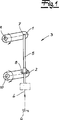
In den
Bei dem Seilzug
Die Seele
Die in Längserstreckung der Seele
Wie bereits erläutert, ist das erste Element
Dieser Vorgang wird mit Hilfe der Zuzieheinrichtung
Kommt es bei dem beschriebenen Zuziehvorgang dazu, dass beispielsweise ein Kleidungsstück zwischen der Kraftfahrzeugtür und der Kraftfahrzeugkarosserie eingeklemmt wird, so kann ein Bediener durch Beaufschlagen der Handhabe bzw. des Außentürgriffes
Zuvor bzw. gleichzeitig fährt die Mitnahmetrommel
Sobald die Seele
Als Folge hiervon ist der Zuziehantrieb
Der der Zuziehklinke
Tatsächlich korrespondiert die Uhrzeigersinndrehung des Innenbetätigungshebels
Man erkennt, dass der Auswerferhebel
In einem weiteren, nicht dargestellten Ausführungsbeispiel kann die Mitnahmetrommel
ZITATE ENTHALTEN IN DER BESCHREIBUNG QUOTES INCLUDE IN THE DESCRIPTION
Diese Liste der vom Anmelder aufgeführten Dokumente wurde automatisiert erzeugt und ist ausschließlich zur besseren Information des Lesers aufgenommen. Die Liste ist nicht Bestandteil der deutschen Patent- bzw. Gebrauchsmusteranmeldung. Das DPMA übernimmt keinerlei Haftung für etwaige Fehler oder Auslassungen.This list of the documents listed by the applicant has been generated automatically and is included solely for the better information of the reader. The list is not part of the German patent or utility model application. The DPMA assumes no liability for any errors or omissions.
Zitierte PatentliteraturCited patent literature
- DE 102007012684 A1 [0003] DE 102007012684 A1 [0003]
- DE 4327782 A1 [0004] DE 4327782 A1 [0004]
- DE 202008007310 U1 [0006] DE 202008007310 U1 [0006]
- DE 102004052599 A1 [0007] DE 102004052599 A1 [0007]
Claims (15)
Priority Applications (9)
| Application Number | Priority Date | Filing Date | Title |
|---|---|---|---|
| DE201120101230 DE202011101230U1 (en) | 2011-05-28 | 2011-05-28 | actuator |
| US14/119,590 US20140345402A1 (en) | 2011-05-28 | 2012-05-26 | Actuating device |
| JP2014511738A JP6269963B2 (en) | 2011-05-28 | 2012-05-26 | Actuator |
| EP12734782.1A EP2715018B1 (en) | 2011-05-28 | 2012-05-26 | Actuating device |
| KR1020137033748A KR20140040753A (en) | 2011-05-28 | 2012-05-26 | Actuating device |
| CA2836314A CA2836314A1 (en) | 2011-05-28 | 2012-05-26 | Actuating device |
| PCT/DE2012/000561 WO2012163330A1 (en) | 2011-05-28 | 2012-05-26 | Actuating device |
| CN201280026245.0A CN103597154B (en) | 2011-05-28 | 2012-05-26 | Activated apparatus |
| US14/219,621 US9638299B2 (en) | 2011-05-28 | 2014-03-19 | Actuating device |
Applications Claiming Priority (1)
| Application Number | Priority Date | Filing Date | Title |
|---|---|---|---|
| DE201120101230 DE202011101230U1 (en) | 2011-05-28 | 2011-05-28 | actuator |
Publications (1)
| Publication Number | Publication Date |
|---|---|
| DE202011101230U1 true DE202011101230U1 (en) | 2012-08-30 |
Family
ID=46507823
Family Applications (1)
| Application Number | Title | Priority Date | Filing Date |
|---|---|---|---|
| DE201120101230 Expired - Lifetime DE202011101230U1 (en) | 2011-05-28 | 2011-05-28 | actuator |
Country Status (8)
| Country | Link |
|---|---|
| US (2) | US20140345402A1 (en) |
| EP (1) | EP2715018B1 (en) |
| JP (1) | JP6269963B2 (en) |
| KR (1) | KR20140040753A (en) |
| CN (1) | CN103597154B (en) |
| CA (1) | CA2836314A1 (en) |
| DE (1) | DE202011101230U1 (en) |
| WO (1) | WO2012163330A1 (en) |
Cited By (2)
| Publication number | Priority date | Publication date | Assignee | Title |
|---|---|---|---|---|
| DE202012010338U1 (en) * | 2012-10-30 | 2014-02-03 | Kiekert Aktiengesellschaft | Motor vehicle door lock |
| DE102021128096A1 (en) | 2021-10-28 | 2023-05-04 | Kiekert Aktiengesellschaft | Closing device for a motor vehicle lock |
Families Citing this family (7)
| Publication number | Priority date | Publication date | Assignee | Title |
|---|---|---|---|---|
| DE102010063868A1 (en) * | 2010-12-22 | 2012-06-28 | Kiekert Ag | Reinforced motor vehicle lock |
| CN103938943B (en) * | 2014-01-22 | 2016-03-02 | 东方通信股份有限公司 | The latch of soft unlatching |
| DE102015005302A1 (en) * | 2014-05-16 | 2015-11-19 | Kiekert Aktiengesellschaft | Motor vehicle door lock |
| DE102014007525A1 (en) * | 2014-05-23 | 2015-11-26 | Kiekert Aktiengesellschaft | Motor vehicle door lock |
| US20150354255A1 (en) * | 2014-06-06 | 2015-12-10 | Brose Schliesssysteme Gmbh & Co. Kg | Lock arrangement for a motor vehicle |
| JP2016008021A (en) * | 2014-06-26 | 2016-01-18 | ヤマハ発動機株式会社 | vehicle |
| US10941592B2 (en) * | 2015-05-21 | 2021-03-09 | Magna Closures Inc. | Latch with double actuation and method of construction thereof |
Citations (4)
| Publication number | Priority date | Publication date | Assignee | Title |
|---|---|---|---|---|
| DE4327782A1 (en) | 1992-08-25 | 1994-03-03 | Mitsui Mining & Smelting Co | Door locking device with a one-movement door opening mechanism |
| DE102004052599A1 (en) | 2004-10-29 | 2006-05-04 | Bayerische Motoren Werke Ag | Lock for motor vehicle door, has opening aid to produce torsional moment in closing direction of latch and activated by opening signal or movement of hand, handgrips or switches until pin is adjusted from opening adjustable range of latch |
| DE102007012684A1 (en) | 2006-05-26 | 2007-11-29 | Brose Fahrzeugteile Gmbh & Co. Kommanditgesellschaft, Coburg | Operating device consists of Bowden sheath and core coupled to lock building group that is activated via pulling force generated by operating system located at operating section of Bowden sheath |
| DE202008007310U1 (en) | 2008-02-15 | 2009-06-25 | Kiekert Ag | Motor vehicle door lock |
Family Cites Families (16)
| Publication number | Priority date | Publication date | Assignee | Title |
|---|---|---|---|---|
| JPS5824585B2 (en) * | 1980-01-10 | 1983-05-21 | 日産自動車株式会社 | Push/pull cable transmission force extraction device |
| FR2618834B1 (en) * | 1987-07-29 | 1989-11-03 | Neiman Sa | CABLE LOCK FOR A MOTOR VEHICLE DOOR HAVING A CONDEMNATION MECHANISM |
| GB2226076B (en) * | 1988-12-17 | 1992-12-02 | Bocklenberg & Motte Bomoro | Vehicle door latches |
| US5531489A (en) * | 1994-09-23 | 1996-07-02 | Atoma International Inc. | Anti-kink cable for automotive door handles |
| US5681068A (en) * | 1995-05-12 | 1997-10-28 | Kiekert Ag | Actuating assembly for motor-vehicle door latch |
| US5639130A (en) * | 1995-05-31 | 1997-06-17 | General Motors Corporation | Rotary door cinching mechanism with manual override |
| GB2328242B (en) * | 1997-05-23 | 2001-05-16 | Rockwell Lvs | Vehicle door latch |
| US5918917A (en) * | 1997-07-22 | 1999-07-06 | General Motors Corporation | Vehicle door latch with cinching mechanism |
| SE514763C2 (en) * | 1998-05-12 | 2001-04-23 | Volvo Ab | Locking device and engine hood for motor vehicles comprising such locking device |
| US6053542A (en) * | 1998-06-26 | 2000-04-25 | General Motors Corporation | Vehicle door latch with cinching mechanism |
| US6062615A (en) * | 1998-09-17 | 2000-05-16 | Kiekert Ag | Actuating assembly for motor-vehicle door latch |
| US6123372A (en) * | 1999-07-21 | 2000-09-26 | Delphi Technologies, Inc. | Door latch |
| JP3887382B2 (en) * | 2004-05-10 | 2007-02-28 | 株式会社ホンダロック | Vehicle door opening and closing device |
| CN101033669A (en) * | 2006-03-06 | 2007-09-12 | 杜再钦 | Vehicle door lock structure |
| GB0604478D0 (en) * | 2006-03-06 | 2006-04-12 | Meritor Technology Inc | Latch system |
| US9850689B2 (en) * | 2011-04-28 | 2017-12-26 | GM Global Technology Operations LLC | Vehicle door cable abutment |
-
2011
- 2011-05-28 DE DE201120101230 patent/DE202011101230U1/en not_active Expired - Lifetime
-
2012
- 2012-05-26 CA CA2836314A patent/CA2836314A1/en not_active Abandoned
- 2012-05-26 EP EP12734782.1A patent/EP2715018B1/en active Active
- 2012-05-26 US US14/119,590 patent/US20140345402A1/en not_active Abandoned
- 2012-05-26 WO PCT/DE2012/000561 patent/WO2012163330A1/en active Application Filing
- 2012-05-26 KR KR1020137033748A patent/KR20140040753A/en not_active Application Discontinuation
- 2012-05-26 JP JP2014511738A patent/JP6269963B2/en active Active
- 2012-05-26 CN CN201280026245.0A patent/CN103597154B/en active Active
-
2014
- 2014-03-19 US US14/219,621 patent/US9638299B2/en active Active
Patent Citations (4)
| Publication number | Priority date | Publication date | Assignee | Title |
|---|---|---|---|---|
| DE4327782A1 (en) | 1992-08-25 | 1994-03-03 | Mitsui Mining & Smelting Co | Door locking device with a one-movement door opening mechanism |
| DE102004052599A1 (en) | 2004-10-29 | 2006-05-04 | Bayerische Motoren Werke Ag | Lock for motor vehicle door, has opening aid to produce torsional moment in closing direction of latch and activated by opening signal or movement of hand, handgrips or switches until pin is adjusted from opening adjustable range of latch |
| DE102007012684A1 (en) | 2006-05-26 | 2007-11-29 | Brose Fahrzeugteile Gmbh & Co. Kommanditgesellschaft, Coburg | Operating device consists of Bowden sheath and core coupled to lock building group that is activated via pulling force generated by operating system located at operating section of Bowden sheath |
| DE202008007310U1 (en) | 2008-02-15 | 2009-06-25 | Kiekert Ag | Motor vehicle door lock |
Cited By (2)
| Publication number | Priority date | Publication date | Assignee | Title |
|---|---|---|---|---|
| DE202012010338U1 (en) * | 2012-10-30 | 2014-02-03 | Kiekert Aktiengesellschaft | Motor vehicle door lock |
| DE102021128096A1 (en) | 2021-10-28 | 2023-05-04 | Kiekert Aktiengesellschaft | Closing device for a motor vehicle lock |
Also Published As
| Publication number | Publication date |
|---|---|
| JP6269963B2 (en) | 2018-01-31 |
| CN103597154A (en) | 2014-02-19 |
| CA2836314A1 (en) | 2012-12-06 |
| KR20140040753A (en) | 2014-04-03 |
| US20140203570A1 (en) | 2014-07-24 |
| JP2014518965A (en) | 2014-08-07 |
| US20140345402A1 (en) | 2014-11-27 |
| US9638299B2 (en) | 2017-05-02 |
| EP2715018A1 (en) | 2014-04-09 |
| CN103597154B (en) | 2015-09-09 |
| EP2715018B1 (en) | 2017-07-12 |
| WO2012163330A1 (en) | 2012-12-06 |
Similar Documents
| Publication | Publication Date | Title |
|---|---|---|
| EP2715018B1 (en) | Actuating device | |
| EP3099871B1 (en) | Electric vehicle door lock with increased operating reliability | |
| DE102008048773A1 (en) | Motor vehicle door lock | |
| DE102011012656A1 (en) | Motor vehicle door lock | |
| DE60018746T2 (en) | LOCKING DEVICE | |
| DE102008048772A1 (en) | Motor vehicle door lock | |
| EP3445930B1 (en) | Motor vehicle door lock | |
| DE102016117282A1 (en) | MOTOR VEHICLE LOCK | |
| DE102017124525A1 (en) | Motor vehicle door lock | |
| DE202013102505U1 (en) | Zuzieheinrichtung for a motor vehicle lock | |
| DE202012002853U1 (en) | Motor vehicle door lock | |
| WO2013087454A1 (en) | Locking device for a cover of a vehicle, method for operation | |
| DE102018124122A1 (en) | Front hood locking of motor vehicles | |
| DE102013108224A1 (en) | Motor vehicle door | |
| DE102019110253A1 (en) | Door lock, in particular motor vehicle door lock | |
| DE102018121383A1 (en) | Motor vehicle door lock | |
| EP3262259A1 (en) | Motor vehicle door lock | |
| DE102020113992A1 (en) | Motor vehicle locking device | |
| DE102017124529A1 (en) | Motor vehicle door lock | |
| DE102009050077A1 (en) | Vehicle lock, has closing catch engaging at rotary latch for implementing closing operation, and mechanism carrying out displacement of closing catch into external engaging position during reaching closing position of latch | |
| DE202008014183U1 (en) | Motor vehicle door lock | |
| EP3513021B1 (en) | Motor vehicle door lock | |
| DE102009051432A1 (en) | Motor vehicle door lock, has locking mechanism and locking lever, where locking mechanism in its open state blocks locking lever | |
| DE102014003106A1 (en) | Motor vehicle door lock | |
| DE102010053179A1 (en) | Motor vehicle door lock is provided with locking units and locking bolt, where release lever units are provided for locking units |
Legal Events
| Date | Code | Title | Description |
|---|---|---|---|
| R207 | Utility model specification |
Effective date: 20121025 |
|
| R163 | Identified publications notified | ||
| R163 | Identified publications notified |
Effective date: 20121218 |
|
| R079 | Amendment of ipc main class |
Free format text: PREVIOUS MAIN CLASS: E05B0065320000 Ipc: E05B0079200000 |
|
| R079 | Amendment of ipc main class |
Free format text: PREVIOUS MAIN CLASS: E05B0065320000 Ipc: E05B0079200000 Effective date: 20140120 |
|
| R150 | Utility model maintained after payment of first maintenance fee after three years | ||
| R150 | Utility model maintained after payment of first maintenance fee after three years |
Effective date: 20140530 |
|
| R151 | Utility model maintained after payment of second maintenance fee after six years | ||
| R158 | Lapse of ip right after 8 years |