KR20140040753A - Actuating device - Google Patents
Actuating device Download PDFInfo
- Publication number
- KR20140040753A KR20140040753A KR1020137033748A KR20137033748A KR20140040753A KR 20140040753 A KR20140040753 A KR 20140040753A KR 1020137033748 A KR1020137033748 A KR 1020137033748A KR 20137033748 A KR20137033748 A KR 20137033748A KR 20140040753 A KR20140040753 A KR 20140040753A
- Authority
- KR
- South Korea
- Prior art keywords
- closing
- lever
- actuating lever
- designed
- locking mechanism
- Prior art date
Links
Images

Classifications
-
- E—FIXED CONSTRUCTIONS
- E05—LOCKS; KEYS; WINDOW OR DOOR FITTINGS; SAFES
- E05B—LOCKS; ACCESSORIES THEREFOR; HANDCUFFS
- E05B79/00—Mounting or connecting vehicle locks or parts thereof
- E05B79/10—Connections between movable lock parts
- E05B79/22—Operative connections between handles, sill buttons or lock knobs and the lock unit
-
- F—MECHANICAL ENGINEERING; LIGHTING; HEATING; WEAPONS; BLASTING
- F16—ENGINEERING ELEMENTS AND UNITS; GENERAL MEASURES FOR PRODUCING AND MAINTAINING EFFECTIVE FUNCTIONING OF MACHINES OR INSTALLATIONS; THERMAL INSULATION IN GENERAL
- F16H—GEARING
- F16H21/00—Gearings comprising primarily only links or levers, with or without slides
- F16H21/10—Gearings comprising primarily only links or levers, with or without slides all movement being in, or parallel to, a single plane
- F16H21/44—Gearings comprising primarily only links or levers, with or without slides all movement being in, or parallel to, a single plane for conveying or interconverting oscillating or reciprocating motions
-
- E—FIXED CONSTRUCTIONS
- E05—LOCKS; KEYS; WINDOW OR DOOR FITTINGS; SAFES
- E05B—LOCKS; ACCESSORIES THEREFOR; HANDCUFFS
- E05B53/00—Operation or control of locks by mechanical transmissions, e.g. from a distance
-
- E—FIXED CONSTRUCTIONS
- E05—LOCKS; KEYS; WINDOW OR DOOR FITTINGS; SAFES
- E05B—LOCKS; ACCESSORIES THEREFOR; HANDCUFFS
- E05B53/00—Operation or control of locks by mechanical transmissions, e.g. from a distance
- E05B53/003—Operation or control of locks by mechanical transmissions, e.g. from a distance flexible
- E05B53/005—Bowden
-
- E—FIXED CONSTRUCTIONS
- E05—LOCKS; KEYS; WINDOW OR DOOR FITTINGS; SAFES
- E05B—LOCKS; ACCESSORIES THEREFOR; HANDCUFFS
- E05B79/00—Mounting or connecting vehicle locks or parts thereof
- E05B79/10—Connections between movable lock parts
- E05B79/20—Connections between movable lock parts using flexible connections, e.g. Bowden cables
-
- E—FIXED CONSTRUCTIONS
- E05—LOCKS; KEYS; WINDOW OR DOOR FITTINGS; SAFES
- E05B—LOCKS; ACCESSORIES THEREFOR; HANDCUFFS
- E05B81/00—Power-actuated vehicle locks
- E05B81/12—Power-actuated vehicle locks characterised by the function or purpose of the powered actuators
- E05B81/20—Power-actuated vehicle locks characterised by the function or purpose of the powered actuators for assisting final closing or for initiating opening
-
- E—FIXED CONSTRUCTIONS
- E05—LOCKS; KEYS; WINDOW OR DOOR FITTINGS; SAFES
- E05B—LOCKS; ACCESSORIES THEREFOR; HANDCUFFS
- E05B81/00—Power-actuated vehicle locks
- E05B81/24—Power-actuated vehicle locks characterised by constructional features of the actuator or the power transmission
- E05B81/25—Actuators mounted separately from the lock and controlling the lock functions through mechanical connections
-
- E—FIXED CONSTRUCTIONS
- E05—LOCKS; KEYS; WINDOW OR DOOR FITTINGS; SAFES
- E05B—LOCKS; ACCESSORIES THEREFOR; HANDCUFFS
- E05B85/00—Details of vehicle locks not provided for in groups E05B77/00 - E05B83/00
-
- Y—GENERAL TAGGING OF NEW TECHNOLOGICAL DEVELOPMENTS; GENERAL TAGGING OF CROSS-SECTIONAL TECHNOLOGIES SPANNING OVER SEVERAL SECTIONS OF THE IPC; TECHNICAL SUBJECTS COVERED BY FORMER USPC CROSS-REFERENCE ART COLLECTIONS [XRACs] AND DIGESTS
- Y10—TECHNICAL SUBJECTS COVERED BY FORMER USPC
- Y10T—TECHNICAL SUBJECTS COVERED BY FORMER US CLASSIFICATION
- Y10T292/00—Closure fasteners
- Y10T292/08—Bolts
- Y10T292/1043—Swinging
- Y10T292/1075—Operating means
- Y10T292/1076—Link and lever
-
- Y—GENERAL TAGGING OF NEW TECHNOLOGICAL DEVELOPMENTS; GENERAL TAGGING OF CROSS-SECTIONAL TECHNOLOGIES SPANNING OVER SEVERAL SECTIONS OF THE IPC; TECHNICAL SUBJECTS COVERED BY FORMER USPC CROSS-REFERENCE ART COLLECTIONS [XRACs] AND DIGESTS
- Y10—TECHNICAL SUBJECTS COVERED BY FORMER USPC
- Y10T—TECHNICAL SUBJECTS COVERED BY FORMER US CLASSIFICATION
- Y10T74/00—Machine element or mechanism
- Y10T74/18—Mechanical movements
- Y10T74/18888—Reciprocating to or from oscillating
- Y10T74/1892—Lever and slide
Landscapes
- Engineering & Computer Science (AREA)
- General Engineering & Computer Science (AREA)
- Mechanical Engineering (AREA)
- Lock And Its Accessories (AREA)
- Power-Operated Mechanisms For Wings (AREA)
Abstract
본 발명은 코어(4)와 피복(5)을 갖는 적어도 하나의 피복 케이블(4, 5)로 차량 도어 록킹 장치(3)의 적어도 2개의 다른 요소(1, 2)에 함께 작용하기 위한 작동 장치에 관한 것으로서, 피복 케이블(4, 5)은 그 길이 방향 범위 내에서 적어도 2개의 힘 전달 유니트(7, 8)를 구비하되, 힘 전달 유니트는 피복 케이블(4, 5)에 작용시 피복 케이블의 한 종단에서는 제 1 요소(1)와 다른 종단에서는 제 2 요소(2)와의 상호 작용을 위하여 설계되며, 2개의 요소(1, 2) 중 하나는 작동 레버(1)로 설계되고, 다른 요소(2)는 록킹 메커니즘(15, 16)을 작동시키는 닫힘/개방 요소(11)이다. The invention relates to an actuating device for acting together on at least two different elements 1, 2 of the vehicle door locking device 3 with at least one sheathed cable 4, 5 having a core 4 and a sheath 5. As regards the present invention, sheathed cables (4, 5) have at least two force transmission units (7, 8) within their longitudinal ranges, the force transmission units of the sheathing cable (4, 5) when acting on the sheathed cables (4, 5). It is designed for interaction with the first element 1 at one end and with the second element 2 at the other end, one of the two elements 1, 2 is designed with an actuating lever 1 and the other element ( 2) is a closing / opening element 11 which activates the locking mechanisms 15 and 16.
Description
본 발명은 코어와 피복을 갖는 적어도 하나의 피복 케이블로 차량 도어 록킹 장치의 적어도 2개의 다른 요소에 함께 작용하기 위한 작동 장치에 관한 것으로서, 여기서 피복 케이블은 그 길이 방향 범위 내에서 적어도 2개의 힘 전달 유니트를 구비하되, 힘 전달 유니트는 피복 케이블에 작용시 피복 케이블의 한 종단에서는 제 1 요소와 다른 종단에서는 제 2 요소와의 상호 작용을 위하여 설계되며, 2개의 요소 중 하나는 작동 레버로 설계된다.The present invention relates to an actuating device for acting together on at least two different elements of a vehicle door locking device with at least one sheath cable having a core and sheath, wherein the sheath cable transmits at least two forces within its longitudinal range. And a force transmission unit designed to interact with the first element at one end of the sheathed cable and the second element at the other end when acting on the sheathed cable, one of which is designed as an actuating lever .
차량 도어 록킹 장치를 위한 작동 장치는 일반적으로 내부 및/또는 외부 도어 핸들과 같은 핸들을 포함하며, 예시적인 경우에서 내부 작동 레버 및/또는 외부 작동 레버와 같은, 차량 도어 록킹 장치 내의 개별 요소들의 도움으로 작동될 수 있다. 내부 작동 레버 및/또는 외부 작동 레버는 작동을 위하여 일반적으로 릴리즈 레버와 기계적으로 연결된다. 릴리즈 레버의 도움으로, 포올은 로터리 래치와의 맞물림 상태에서 규칙적으로 해제되어 로터리 래치는 스프링의 도움으로 개방될 수 있으며 이전에 유지된 록킹 볼트를 해제할 수 있다. 그 결과, 차량 도어 록킹 장치를 포함한 차량 도어는 열려질 수 있다 The actuation device for the vehicle door locking device generally comprises a handle, such as an inner and / or outer door handle, and in an exemplary case aids of individual elements in the vehicle door locking device, such as an inner actuating lever and / or an outer actuating lever. Can be operated. The inner actuating lever and / or the outer actuating lever are generally mechanically connected to the release lever for actuation. With the aid of the release lever, the poles are regularly released in engagement with the rotary latches so that the rotary latches can be opened with the aid of springs and release the previously held locking bolts. As a result, the vehicle door including the vehicle door locking device can be opened.
DE 10 2007 012 684 A1에 따른 일반적인 선행 기술은 위에서 언급된 설계의 작동 장치를 개시하며, 이 장치에서 피복 케이블의 코어에서의 장력의 발생은 록킹 조립체의 작동을 야기한다. 이 선행 기술의 상세한 설명에서, 그리고 도 5에 도시된 실시예에 따라 2개의 다른 레버가 코어의 도움으로 동시에 작동될 수 있다. 이 목적을 위하여, 이격된 케이블 고정구(fittings)가 코어에 연결되어 있다. 기본적으로, 이 장치는 특정 (개방) 위치에서 차량의 슬라이딩 도어를 유지하는 기능을 수행한다. The general prior art according to
DE 43 27 782 A1에 개시된 다른 선행 기술은 단일 운동 도어 개방 메커니즘을 갖는 도어 닫힘 장치를 언급한다. 이 목적을 위하여, 피복 케이블의 코어는 플랜지와 맞물리며, 또한 하중 지지부(loading bearing part)를 포함한다. 이 절차는 내부 록킹 버튼이 언록킹 위치로 이동하는 것을 야기한다. 이는 내부 개방 핸들 또는 내부 도어 핸들이 작동할 때, 언록킹 상태가 가정되고 동시에 도어가 개방되는 방식으로 피복 케이블의 코어가 작동함에 따라 차량 도어 록킹 장치가 아직 록킹된 상태에 있을지라도 각 도어 개방 작동이 실행되고 수행되는 것을 의미한다.Another prior art disclosed in DE 43 27 782 A1 refers to a door closing device with a single movement door opening mechanism. For this purpose, the core of the sheathed cable engages the flange and also includes a loading bearing part. This procedure causes the internal locking button to move to the unlocking position. This means that when the inner opening handle or the inner door handle operates, each door opening operation is performed even if the vehicle door locking device is still in the locked state as the core of the sheathed cable operates in such a way that the unlocking state is assumed and the door is opened at the same time. This means that it is executed and performed.
공지된 수단들은 일반적으로 성공적인 것으로 입증되었으나, 부분적으로는 복잡한 설계에 기초한다. 또한, 오늘 날 차량 도어 록킹 장치에 관하여 부가적인 요구 조건들이 제시되고 있으나, 이는 지금까지 충분하게 고려되지 않고 있다. 예를 들어, 현재의 차량 도어 록킹 장치는 보통 부가적인 닫힘 및 개방 수단을 포함하고 있으며, 현재 이는 (아직까지) 고급 차량에만 사용되고 있으나, 앞으로는 대량 판매 시장에 의하여 사용될 수 있다. Known means have generally proven successful, but are based, in part, on complex designs. In addition, additional requirements have been proposed for vehicle door locking devices today, which have not been fully considered to date. For example, current vehicle door locking devices usually include additional closing and opening means, which are currently used only for luxury vehicles (yet), but may be used by the mass market in the future.
닫힘 수단은 일반적으로 일반적인 전기 모터의 도움으로 테일게이트의 전동화된 닫힘을 제공한다. 그 결과, 특정 기능적 위치, 대부분의 경우 중간 닫힘 위치에 도달하면, 차량 도어 록킹 장치의 록킹 메커니즘, 즉 일반적으로 포올과 로터리 래치의 조합은 종단 위치로 또는 완전히 닫혀진 위치로 이동한다. 닫힘 수단이 완전한 닫힘 작동을 수행하기 전에 사용자가 단지 각 도어 또는 테일게이트를 중간 닫힘 위치로 이동시켜야만 함으로써 이는 특히 수월한 작동을 야기한다. 이러한 닫힘 수단의 예가 본 출원인의 독일실용신안 DE 20 2008 007310 U1에 개시되어 있으며, 이 예에서 닫힘 수단을 위한 구동부는 선형 구동부로서 설계되고 닫힘 포올에 선회 가능하게 연결된 레버에 작용한다. 닫힘 포올은 로터리 래치 상의 윤곽부로 맞물리며 원하는 닫힘 이동을 야기한다. The closing means generally provide for motorized closing of the tailgate with the help of a common electric motor. As a result, when a certain functional position, in most cases an intermediate closed position, is reached, the locking mechanism of the vehicle door locking device, generally the combination of the pole and the rotary latch, moves to the end position or to the fully closed position. This results in a particularly easy operation by the user only having to move each door or tailgate to the intermediate closed position before the closing means performs a full closing operation. An example of such a closing means is disclosed in the Applicant's German Utility Model DE 20 2008 007310 U1, in which the drive for the closing means is designed as a linear drive and acts on a lever pivotally connected to the closing pole. The closing pole engages the contour on the rotary latch and causes the desired closing movement.
일반적으로, 개방 보조 장치는 또한 차량 도어 록킹 장치의 관련된 록킹 메커니즘이 모터의 도움으로 개방될 수 있다는 것을 보장하는 것으로 알려져 있다. 이러한 개방 장치 또는 개방 보조 장치의 예가 DE 10 2004 052 599 A1에 개시되어 있다. 다시 한번 말하면, 이 장치의 주요 목적은 편안함의 수준을 증가시키는 것이다.In general, the opening assistance device is also known to ensure that the associated locking mechanism of the vehicle door locking device can be opened with the aid of a motor. Examples of such opening devices or opening auxiliary devices are disclosed in DE 10 2004 052 599 A1. Once again, the main purpose of the device is to increase the level of comfort.
예를 들어 재킷, 코트 또는 옷의 유사한 조각 또는 사용자의 신체 일부가 닫힘 도어와 차체 사이의 간격에 끼일 때, 공지된 닫힘 수단 또는 개방 장치는 문제를 야기할 수 있다. 이는 일반적으로 닫힘 수단을 정지되게 한다. 그러나, 이러한 상황에서 사용자는 외부 도어 핸들을 직감적으로 작동시키고 닫힘 수단이 곧바로 정지되고 또한 동시에 차량 도어가 열려 끼여진 부분이 해제되는 것을 기대한다. 현재는, 간단한 설계 방식으로 원하는 작동을 발생시키고 허용하는 어떠한 확실한 해결책도 유용하지 않다. Known closing means or opening devices can cause problems when, for example, a jacket, coat or similar piece of clothing or a user's body part is caught in the gap between the closing door and the vehicle body. This generally causes the closing means to stop. However, in such a situation, the user expects to operate the outer door handle intuitively, the closing means are immediately stopped, and at the same time the part where the vehicle door is opened and the jammed part is released. At present, no obvious solution is possible to generate and allow the desired operation in a simple design manner.
본 발명은 닫힘 및 개방 수단에 의하여 야기되는 작동 및 안전 관련 문제가 적은 노력으로도 방지되는 방식으로 작동 장치의 추가적인 발전의 기술적 문제에 기초한다.The invention is based on the technical problem of further development of the operating device in such a way that the operation and safety related problems caused by the closing and opening means are avoided with little effort.
이 기술적 문제점을 해결하기 위하여, 본 발명에 개시된 바와 같은 차량 도어 록킹 장치의 적어도 2개의 다른 요소에 함께 작용하기 위한 일반적인 작동 장치는 2개의 요소 중 다른 요소는 록킹 메커니즘에 작용하는 닫힘/개방 요소인 것을 특징으로 한다. 즉, 한편으로는 차량 도어 록킹 장치의 적어도 2개의 다른 요소는 작동 레버로서 설계되고 다른 한편으로는 닫힘/개방 요소 또는 이들과 상호 작용하고 록킹 메커니즘에 작용하는 요소로 설계된다. In order to solve this technical problem, a general actuating device for working together on at least two different elements of the vehicle door locking device as disclosed in the present invention is that the other of the two elements is a closing / opening element that acts on the locking mechanism. It is characterized by. In other words, at least two other elements of the vehicle door locking device are designed as actuation levers and on the other hand as closed / open elements or elements which interact with them and act on the locking mechanism.
일반적으로, 제1 요소는 작동 레버로서 설계되는 반면에, 제 2 요소는 닫힘 요소이다. 양 요소는 피복 케이블과 상호 작용하며, 이 목적을 위하여 2개의 힘 전달 유니트를 포함한다. 피복 케이블에 힘이 작용하자마자. 작동 레버와 닫힘 요소는 배치된 힘 전달 유니트를 통하여 작동된다. In general, the first element is designed as an actuating lever, while the second element is a closing element. Both elements interact with the sheathed cable and include two force transmission units for this purpose. As soon as power is applied to the sheathed cable. The actuation lever and the closing element are actuated via a force transfer unit arranged.
작동 레버는 내부 작동 레버, 외부 작동 레버, 주 작동 레버 등이다. 내부 작동 레버는 내부 도어 핸들에 의하여 규칙적으로 작용한다. 한편, 작동을 위하여 외부 작동 레버는 외부 도어 핸들에 기계적으로 연결되어 있다. 주 작동 레버는 내부 작동 레버와 외부 작동 레버 사이에 배치될 수 있으며, 또는 전동 구동부에 의하여 작용될 수 있다. The actuating lever is an internal actuating lever, an external actuating lever, a main actuating lever, or the like. The inner actuating lever acts regularly by the inner door handle. On the other hand, the external operating lever is mechanically connected to the external door handle for operation. The main actuating lever can be arranged between the inner actuating lever and the outer actuating lever, or can be actuated by an electric drive.
예에서, 내부 도어 핸들이 사용자에 의하여 작동하자마자, 내부 도어 레버를 외부 작동 레버에 결합하는 피복 케이블은 또한 작동된다. 피복 케이블은 그 후 힘에 의하여 굴절된다. 그 결과, 내부 작동 레버와 닫힘 요소 또는 닫힘/개방 요소는 작동된다. In an example, as soon as the inner door handle is operated by the user, the sheathed cable that couples the inner door lever to the outer actuating lever is also actuated. The sheathed cable is then bent by force. As a result, the inner actuating lever and the closing element or the closing / opening element are actuated.
따라서, 이 예에서의 닫힘 요소가 록킹 메커니즘에 맞물리고 내부 도어 핸들이 사용자에 의하여 작동되는 경우, 가해진 힘은 내부 작동 레버와 닫힘 요소가 작동하는 것을 보장한다. 결과적으로, 록킹 메커니즘은 정상적으로 개방되고, 닫힘 수단은 닫힘 요소에 의하여 비효율적인 것으로 된다. Thus, when the closing element in this example engages the locking mechanism and the inner door handle is actuated by the user, the force applied ensures that the inner actuating lever and the closing element operate. As a result, the locking mechanism is normally opened, and the closing means becomes inefficient by the closing element.
이를 이루기 위하여, 내부 도어 핸들에 의하여 작동하는 내부 작동 레버는 릴리즈 레버에 작용하며, 결국 릴리즈 레버는 로터리 래치로부터 포올을 들어 올린다. 이는 내부 작동 레버와의 피복 케이블의 제 1 힘 전달 유니트의 기계적인 결합의 결과로서 이루어진다. 피복 케이블이 시간 중복(time overlap)을 갖고 다른 제 2 힘 전달 유니트를 통하여 닫힘 요소와 상호 작용함에 따라 닫힘 요소는 록킹 메커니즘과의 맞물림으로부터 해제된다. 이를 이루기 위하여, 대부분의 경우 닫힘 요소는 이전에 맞물린 로터리 래치에서 벗어나 선회한다. 그러나 대부분의 경우 설명된 조치는 외부 작동 레버 체인, 즉 외부 도어 핸들과 외부 작동 레버 사이의 상호 작동에서 관측될 수 있다. 이 경우, 외부 작동 레버는 릴리즈 레버에 작용하는 반면에, 피복 케이블은 닫힘 요소를 로터리 래치로부터 벗어나 선회시킨다. To achieve this, an internal actuating lever actuated by the inner door handle acts on the release lever, which in turn releases the pole from the rotary latch. This is done as a result of the mechanical coupling of the first force transmission unit of the sheathed cable with the inner actuating lever. As the sheathed cable has a time overlap and interacts with the closing element through another second force transmission unit, the closing element is released from engagement with the locking mechanism. To achieve this, in most cases the closing element pivots away from the previously engaged rotary latch. However, in most cases the measures described can be observed in the external actuating lever chain, ie the interaction between the outer door handle and the external actuating lever. In this case, the external actuating lever acts on the release lever, while the sheathed cable pivots the closing element away from the rotary latch.
닫힘 요소가 록킹 메커니즘의 로터리 래치에 접촉하는 닫힘 포올로 설계된다면, 이는 특히 성공적이다. 대부분의 경우, 레버 특히, 닫힘 레버는 닫힘 폴에 배치되고 닫힘 장치에 의하여 작동된다. 로터리 래치가 어떤 특정 위치, 대부분의 경우 중간 닫힘 위치에 도달하자마자, 닫힘 포올은 로터리 래치 상의 닫힘 윤곽부와 맞물린다. 동시에 닫힘 동작이 시작되고 또한 레버에 연결된 닫힘 포올이 로터리 래치를 중간 닫힘 위치에서 종단 위치 또는 완전 닫힘 위치로 이동시키는 방식으로 닫힘 동작이 레버 또는 닫힘 레버 상에 작용한다. 이 과정 동안에 예를 들어 옷 자락이 차체와 닫히는 차량 도어 사이의 간격에 끼이는 경우, 말하자면 사용자에 의한 외부 도어 핸들의 수동 작동이 (제 2 요소의) 닫힘 포올이 튀어나오고 차량 도어 록킹 장치가 개방되는 것을 보장한다. This is particularly successful if the closing element is designed with a closing pole that contacts the rotary latch of the locking mechanism. In most cases, the lever, in particular the closing lever, is arranged in the closing pawl and is operated by the closing device. As soon as the rotary latch reaches a certain position, in most cases the intermediate closed position, the closing pole engages the closing contour on the rotary latch. At the same time the closing action is initiated and the closing action acts on the lever or the closing lever in such a way that the closing pole connected to the lever moves the rotary latch from the intermediate closing position to the end position or the fully closed position. During this process, for example, if the hem is pinched in the gap between the body and the closing vehicle door, the manual operation of the external door handle by the user, ie, the closing pole (of the second element) pops out and the vehicle door locking device opens. To ensure that
이 두 가지 작동은 반드시 동시에 일어나야만 하는 것은 아니나, 대신 시간 중첩은 특히 포올이 분리되면 닫힘 폴이 (스프링의 도움으로) 그 개방 위치로 이동하자마자 닫힘 포올이 로터리 래치를 떠난다는 사실이면 충분하다.These two operations do not have to occur at the same time, but instead the time superposition is sufficient if the closing pawl leaves the rotary latch as soon as the closing pole moves to its open position (with the aid of a spring).
2개의 힘 전달 유니트를 제공하기 위하여, 피복 케이블은 일반적으로 제 1 힘 전달 유니트를 한정하는 제 1 요소에 걸려있다. 제 1 요소는 일반적으로 외부 작동 레버이며, 제 1 힘 전달 유니트는 이 외부 작동 레버에 배치되어 있다. 제 2의 이격된 요소는 대부분의 경우에 닫힘 포올이다. 이 시점에서, 피복 케이블은 제 2 힘 전달 유니트로서 구동 드럼을 포함한다. In order to provide two force transmission units, the sheathed cable is generally hung on a first element defining the first force transmission unit. The first element is generally an external actuating lever and the first force transmission unit is arranged at this external actuating lever. The second spaced apart element is in most cases a closed pool. At this point, the sheathed cable comprises a drive drum as the second force transmission unit.
피복 케이블의 작동에 따라 구동 드럼은 일반적으로 이젝션 레버 상의 멈춤부와 상호 작용하며 결국 닫힘 포올에 작용한다. 멈춤부는 일반적으로 수용 슬롯을 갖는 아치형 멈춤부이다. 피복 케이블의 대부분은, 위에서 설명한 바와 같은 이젝션 레버 상의 멈춤부와 상호 작용하는 구동 드럼을 넘어 수용 슬롯을 통과한다. Depending on the operation of the sheathed cable, the drive drum generally interacts with the stops on the ejection lever and eventually acts on the closing pole. The stop is generally an arcuate stop with a receiving slot. Most of the sheathed cable passes through the receiving slot beyond the drive drum which interacts with the stop on the ejection lever as described above.
구동 드럼이 멈춤부에 부딪히고 이러한 방식으로 이젝션 레버를 선회시키자 마자 이젝션 레버는 또한 닫힘 요소 또는 닫힘 포올을 록킹 메커니즘으로부터 분리할 수 있다. 이 목적을 위하여, 작동시 이젝션 레버는 닫힘 요소의 작동 레버에 대항하여 이동한다. 그 결과, 록킹 메커니즘 내의 닫힘 요소의 (가능한) 맞물림이 해제된다.As soon as the drive drum hits the stop and pivots the ejection lever in this manner, the ejection lever can also separate the closing element or the closing pole from the locking mechanism. For this purpose, in operation the ejection lever moves against the actuating lever of the closing element. As a result, the (possible) engagement of the closing element in the locking mechanism is released.
피복 케이블의 코어와의 이 작동적인 연결에 더하여, 이젝션 레버는 또한 내부 작동 레버와 기계적으로 연결될 수 있다. 작동하자마자 내부 작동 레버가 내부 작동 이젝션 레버를 통하여 닫힘 요소를 위한 이젝션 레버에 작용하는 방식으로 이러한 설계가 일반적으로 선택된다. 이는 내부 도어 핸들의 도움으로 힘이 내부 작동 레버 상에 작용할 때 내부 작동 이젝션 레버 또한 작동된다는 것을 의미한다. 내부 작동 이젝션 레버는 피복 케이블이 작동하는 유사한 방식으로 닫힘 요소를 위한 이젝션 레버에 작용한다. 이는 내부 작동 이젝션 레버를 통하여 닫힘 요소를 록킹 메커니즘으로부터 기계적으로 분리하기 위하여 이 작동이 또한 이젝션 레버와 부합한다는 것을 의미한다. In addition to this operative connection with the core of the sheathed cable, the ejection lever can also be mechanically connected with the internal actuation lever. This design is generally chosen in such a way that as soon as the actuation acts on the ejection lever for the closing element via the inner actuation ejection lever. This means that with the aid of the inner door handle, the inner actuation ejection lever is also actuated when a force acts on the inner actuating lever. The internally operated ejection lever acts on the ejection lever for the closing element in a similar manner in which the sheathed cable operates. This means that this actuation also coincides with the ejection lever in order to mechanically separate the closing element from the locking mechanism via the internal actuation ejection lever.
위상적인 관점(topological point of view)으로부터, 록킹 메커니즘 평면과 비교할 때 제 2 요소 또는 이젝션 레버와 (외부) 작동 레버가 평행 평면 상에 배치되는 것이 성공적인 것으로 입증되었다. 반대로, 내부 작동 레버와 내부 작동 이젝션 레버는 록킹 메커니즘 평면과 직교하는 평면 내에 배치된다. 따라서 록킹 메커니즘 평면에 직교하는 평면 내에서의 내부 작동 레버의 이동을 이 록킹 메커니즘 평면 또는 이와 평행한 평면에서의 회전 이동으로 전환하기 위하여 내부 작동 이젝션 레버는 제공되어야만 하며, 닫힘 요소에 할당된 이젝션 레버는 원하는 힘으로 작동된다. From a topological point of view, it has proved successful that the second element or the ejection lever and the (outer) actuating lever are arranged on a parallel plane as compared to the locking mechanism plane. In contrast, the inner actuation lever and the inner actuation ejection lever are disposed in a plane orthogonal to the locking mechanism plane. Therefore, in order to convert the movement of the internal actuating lever in a plane orthogonal to the locking mechanism plane to the rotational movement in this locking mechanism plane or a plane parallel thereto, an internal actuating ejection lever must be provided and the ejection lever assigned to the closing element Is operated with the desired force.
그 결과 차량 도어 록킹 장치를 위한 작동 장치가 제공되며, 이 작동 장치는 일반적으로 한 종단에서 외부 작동 레버에 그리고 다른 한 종단에서 닫힘 요소의 닫힘 포올에 함께 작용하기에 적합하고 또한 함께 작용하도록 설계되어 있다. 따라서 어떠한 (당김) 힘으로 작동 장치의 피복 케이블이 작동하자마자, 외부 작동 레버는 굴절되고 닫힘 폴은 록킹 메커니즘으로부터 들어 올려진다. 어떠한 경우에 로터리 래치가 (스프링의 도움으로) 개방 이동을 시작하지마자 닫힘 포올이 록킹 메커니즘으로부터 기계적으로 들어 올려지는 방식으로 이는 일반적으로 시간 중첩(a time overlap)을 갖고 발생한다. As a result, an actuating device for a vehicle door locking device is provided, which is generally adapted to work together and designed to work together with the external actuating lever at one end and with the closing pole of the closing element at the other end. have. Thus, as soon as the sheathing cable of the actuating device is operated with any (pulling) force, the outer actuating lever is deflected and the closing pawl is lifted from the locking mechanism. In some cases, this typically occurs with a time overlap in such a way that the closing pole is mechanically lifted from the locking mechanism as soon as the rotary latch starts to open movement (with the aid of a spring).
이는 간단한 방식으로 편안함의 수준을 현저하게 증가시킨다. 예를 들어, 닫힘 동작 동안의 부정확한 기능 또는 안전 문제는 외부 도어 핸들을 작동하는 사용자에 의한 직감적인 과정의 한 부분으로서 사용자에 의하여 직접적으로 그리고 신속하게 종료될 수 있다. 이젝션 레버에 의하여 닫힘 요소가 록킹 메커니즘으로부터 분리됨에 따라 이는 닫힘 동작을 중단시킨다. 동시에 이러한 방식으로 작동하는 차량 도어는 원하는 대로 개방된다. 외부 도어 핸들, 외부 작동 레버 그리고 닫힘 포올 또는 닫힘 폴에 할당된 이젝션 레버를 연결하기 위한 피복 케이블이 단지 2개의 부착점을 포함함에 따라 이 모든 것은 빠르게 그리고 설계 및 설치의 노력 없이 이루어진다. 이 부착점 또는 힘 전달 유니트는 용이하게 제공될 수 있다. 이 점에서 수행되는 제 2 힘 전달 유니트 또는 구동 드럼은 피복 케이블에 맞추어진 공장 제품(factory)일 수 있으며, 따라서 제 1 힘 전달 유니트를 제공하기 위하여 피복 케이블은 조립 동안에 외부 작동 레버 내에 단지 삽입되어야만 한다. 이들이 본 발명의 주요 이점이다. This significantly increases the level of comfort in a simple manner. For example, incorrect function or safety issues during the closing operation can be terminated directly and quickly by the user as part of an intuitive process by the user operating the outer door handle. This interrupts the closing operation as the closing element is separated from the locking mechanism by the ejection lever. At the same time the vehicle door operating in this way is opened as desired. All of this is quick and without design and installation effort, as the sheathed cable for connecting the outer door handle, the external actuating lever and the ejection lever assigned to the closing pole or closing pole contains only two attachment points. This attachment point or force transmission unit can be easily provided. The second force transmission unit or drive drum carried out at this point may be a factory fitted to the sheathed cable, so that the sheathed cable should only be inserted into the external actuating lever during assembly to provide the first force transfer unit. do. These are the main advantages of the present invention.
도 1은 본 발명의 작동 장치의 개략적인 개요를 도시한 도면.
도 2는 본 발명의 작동 장치의 실제적인 디자인을 갖는 차량 도어 록킹 장치를 도시한 도면.1 shows a schematic overview of the operating device of the invention;
Figure 2 shows a vehicle door locking device having a practical design of the actuating device of the invention.
이하, 단지 하나의 예를 도시한 도면을 참고하여 본 발명을 상세히 설명한다. Hereinafter, the present invention will be described in detail with reference to the drawings showing only one example.
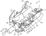
도 1 및 도 2는 차량 도어 록킹 장치(3)의 적어도 2개의 다른 요소(1, 2)에 함께 작용하기 위한 작동 장치를 도시한다. 이 목적을 위하여 작동 장치는 주요 요소로서 피복 케이블(4, 5)을 포함한다. 피복 케이블(4, 5)은 코어(4) 그리고 피복(5)을 포함한다. 1 and 2 show an actuating device for acting together on at least two
본 실시예에서, 피복 케이블(4, 5)은 보덴 케이블(4, 5; Bowden cable)이다. 그 피복(5)은 정지 위치에 있으며, 차량 도어 록킹 장치(3)에 의하여 지지된다. 반대로, 코어(4)는 피복(5) 내에서 이동 가능하며, 특히 도 1에서 화살표로 도시된 바와 같이 핸들(6)로부터 차량 도어(3)의 요소(1, 2) 상으로의 당김 이동을 수행할 수 있다. 비록 제한하지는 않지만 그리고 본 발명을 위하여 의무적인 것은 아니지만, 본 실시예에서, 핸들(6)은 외부 도어 핸들(6)이다. In this embodiment, the sheathed
피복 케이블(4, 5)의 코어(4)는 길이 방향 범위 내의 적어도 2개의 힘 전달 유니트(7, 8)를 포함하며, 이들은 이격되어 있다. 실제로, 도 1은 코어(4)의 길이 방향 범위를 따르는, 코어(4)의 한 종단에서의 제 1 힘 전달 유니트(7) 및 이격된 제 2 힘 전달 유니트(8)를 도시하고 있다. 제 1 힘 전달 유니트(7)는 후크 또는 비슷한 연결 요소이며, 코어(4)의 종단의 도움으로 제 1 요소(1)의 개구에 부착된다. 반대로 제 2 힘 전달 유니트(8)는 공장에서부터 부착된 또는 나중에 코어(4)에 부착된 구동 드럼(8)으로써 설계되어 있다. The
서로 이격되고 코어(4)의 길이 방향 범위 내에 배치된 힘 전달 유니트(7, 8)는 코어(4)가 핸들(6)의 도움으로 작동할 때 한편으로는 제 1 요소(1)와 상호 작용하도록, 다른 한편으로는 제 2 요소(2)와 상호 작용하도록 설계되어 있다. 코어(4) 상으로의 힘의 작용은 실제로 이 점에서라면 제 1 요소(1) 또는 차량 도어 록킹 장치(3)의 외부 작동 레버(1)가 그 축(9)을 중심으로 도 1에서 화살표로 나타난 바와 같이 시계 방향으로 선회하도록 한다. 힘이 코어(4)에 작용될 때, 제 2 요소(2)는 또한 관련된 축(10)을 중심으로 시계 방향으로 선회된다. 한 예에서, 제 2 요소(2)는 닫힘 요소(11)에 할당된 이젝션 레버(2; ejection lever)이다. 닫힘 요소(11)는 닫힘 레버(12)에 기계적으로 연결되어 있다. 실제로, 닫힘 요소(11)는 닫힘 레버(12) 상에 선회 가능하게 장착된 닫힘 포올(11)이다. 피복 케이블(13)을 통한, 도 2에서만 지시된, 닫힘 구동부(14)에 의하여 닫힘 레버(12)는 작동한다. 닫힘 구동부(14), 피복 케이블(13), 닫힘 레버(12) 그리고 마지막으로 닫힘 요소 또는 닫힘 포올(11)은 함께 닫힘 수단(11, 12, 13, 14)을 형성한다. The
이미 설명된 바와 같이, 본 실시예에서의 제 1 요소(1)는 외부 작동 레버(1)로써 설계되어 있다. 원칙적으로, 제 1 요소(1)는 또한 내부 작동 레버일 수 있거나 또는 일반적으로 차량 도어 록킹 장치(3)의 작동 레버일 수 있다. 닫힘 요소(11)는 록킹 메커니즘(15, 16)에 작용하며, 여기서 록킹 메커니즘은 로터리 래치(15) 그리고 일반적인 방식으로 로터리 래치(15)와 상호 작용하는 포올(16)로 이루어진다. 록킹 메커니즘(15, 16)을 닫기 위하여 닫힘 요소 또는 닫힘 포올(11)은 로터리 래치(15) 상의 윤곽부 또는 닫힘 윤곽부(17)에 맞물린다. 이렇게 하여, 록킹 메커니즘(15, 16)에 의하여 이전에 지지되고 차량 도어에 연결된 록킹 볼트는 집어 넣어진다. 대응하는 차량 도어는 그 후 차체를 향하여 이동한다. As already explained, the
이 작동은 닫힘 수단(11, 12, 13, 14)의 도움으로 수행된다. 한 예에서, 로터리 래치(15)가 중간 록킹 위치에 있을 때, 닫힘 수단(11, 12, 13, 14) 또는 닫힘 구동부(14)는 작동하기 시작된다. 닫힘 요소 또는 닫힘 포올(11)은 그 후 로터리 래치(15) 상의 윤곽부(17) 내에 맞물려진다. 동시에, 닫힘 작동(14)은 시작되며 도 2에 도시된 화살표의 방향으로 피복 케이블(13)에 작용한다. 그 결과, 닫힘 레버(12)는 도 2에 지시된 바와 같이 그 축을 중심으로 반시계 방향으로 이동하여 로터리 래치(15) 상의 윤곽부(17)에 맞물려진 닫힘 포올(11)이 지시된 시계 방향으로 그리고 중간 닫힘 위치로부터 완전히 닫혀진 위치로 로터리 래치(15)를 이동시키는 것을 보장한다. This operation is carried out with the help of the closing means 11, 12, 13, 14. In one example, when the
설명된 닫힘 작동 동안, 예를 들어 옷 자락이 차량 도어와 차체 사이에 끼이게 된다면, 사용자는 핸들 또는 외부 도어 핸들을 작동시킴으로써 닫힘 작동을 기계적으로 중단시킬 수 있고 동시에 차량 도어를 열 수 있다. 사실, 외부 도어 핸들(6)의 작동은 피복 케이블(4, 5)의 코어(4)가 도 1 그리고 도 2에 지시된 바와 같이 작동되는 것을 보장한다. 그 결과, 외부 작동 레버(1)는 시계 방향으로 선회(도 1 참조)하여 명확하게 도시되지 않은 릴리즈 레버에 작용하며, 이는 결과적으로 로터리 래치(15)로부터 포올(16)을 분리한다. 축을 중심으로 반시계 방향으로의 그리고 도 2에서 화살표로 지시된 바와 같은 포올(16)의 이동은 이에 대응한다.During the described closing operation, for example, if a hem is caught between the vehicle door and the vehicle body, the user can mechanically stop the closing operation by operating the handle or the outer door handle and at the same time open the vehicle door. In fact, the operation of the
이에 앞서 또는 동시에, 구동 드럼(8)은 제 2 요소(2) 상의 멈춤부(18)에 대항하여 또는 닫힘 포올(11)에 할당된 이젝션 레버(2)에 대항하여 이동한다. 멈춤부(18)는 아치형 멈춤부로써 설계되며 또한 수용 슬롯(19)을 포함한다. 피복 케이블(4, 5)의 코어(4)는 수용 슬롯(19)을 통과한다. 사실, 코어(4)는 구동 드럼(18)의 다른 측부 상의 수용 슬롯(19)을 통과한다.Prior to this or simultaneously, the
코어(4)가 외부 도어 핸들(6)의 도움으로 도시된 화살표의 방향으로 작동하자마자, 멈춤부(18)에 대항하여 이동하는 구동 드럼(8)은 이젝션 레버(2)가 그 축(20)을 중심으로 -화살표로 지시된 바와 같이- 시계 방향으로 선회되는 것을 보장한다. 이젝션 레버(2)의 이 시계 방향 이동은 닫힘 포올(11)이 로터리 래치(15)에서 윤곽부(17; controur)로부터 분리되는 것을 보장한다. 이 목적을 위하여, 닫힘 포올(11)은 작동 저널(21)을 포함하며, 작동시 이젝션 레버(2)는 구동 드럼(8)의 도움으로 이 작동 저널(21)에 대항하여 이동한다. As soon as the
그 결과, 닫힘 구동부(11, 12, 13, 14) 그리고 닫힘 요소 또는 닫힘 포올(11)은 록킹 메커니즘(15, 16)으로부터 기계적으로 분리된다. 따라서 록킹 메커니즘(15, 16)은 닫힘 조건에서 더 이상 작동하지 않는다. 그 결과, -닫힘 이동의 방향 시계 방향과 반대로- 반시계 방향 이동을 수행함으로써 포올(16)의 분리 후에 로터리 래치(15)는 스프링의 도움으로 개방할 수 있다. 로터리 래치(15)에 의하여 이전에 유지된 그리고 명확하게 도시되지 않은 록킹 볼트가 해제된다. 동일한 것이 록킹 볼트가 연결된 차량 도어를 위해서 작용한다. As a result, the closing
닫힘 포올(11)에 할당된 이젝션 레버(2)는 단지 코어(4)와 피복 케이블(4, 5)을 통하여 외부 도어 핸들(6)에 기계적으로 연결되지 않는다. 대신, 이젝션 레버(2)는 내부 작동 레버(22)와 기능적으로 그리고 기계적으로 상호 작용할 수 있다. 결과적으로 내부 작동 레버(22)는 -도면에 도시되지 않은- 내부 도어 핸들에 기계적으로 연결된다. 내부 도어 핸들의 작동은 -지시된 바와 같이- 내부 작동 레버(22)가 그 축을 중심으로 시계 방향으로 선회되게 한다. -도시되지 않은- 내부 도어 핸들의 작동시 내부 작동 레버(22)의 이 시계 방향 이동은 내부 작동 이젝션 레버(23)에 의하여, 닫힘 포올(11)에 할당된 이젝션 레버(2)로 전달된다. The
사실, 내부 작동 레버(22)의 시계 방향 이동은 결과적으로 반시계 방향으로 선회하는 내부 작동 이젝션 레버(23)에 대응한다. 이는 내부 작동 이젝션 레버(23)가 이젝션 레버(2) 상에서 멈춤부 에지(24)와 맞물리게 한다. 이는 작동 시에 내부 작동 이젝션 레버(23)를 통하여 내부 작동 레버(22)가 닫힘 포올(11)에 할당된 이젝션 레버(2)에 작용한다는 것을 의미한다. 이 목적을 위하여, 반시계 방향 이동 동안에 내부 작동 이젝션 레버(23)는 멈춤부(24)에 대항하여 이동하며, -외부 도어 핸들(6)에 의하여 작동될 때- 이젝션 레버(2)가 시계 방향으로 선회되고 닫힘 포올(11)을 로터리 래치(15)로부터 분리하는 것을 보장한다.In fact, the clockwise movement of the
이젝션 레버(2)와 외부 작동 레버(1)가 록킹 메커니즘(15, 16)에 의하여 한정된 록킹 메커니즘 평면과 비교하여 평행한 평면 상에 배치된 것이 명백하다. 반대로, 내부 작동 레버(22)와 내부 작동 이젝션 레버(23)는 록킹 메커니즘 평면에 직교하는 평면 상에 배치된다. 이 목적을 위하여, 록킹 메커니즘(15, 16)은 L-형 록킹 케이스(25)의 L-형 레그 내에 배치되는 반면에, 내부 작동 레버(22)와 내부 작동 이젝션 레버(23)는 다른 L-형 레그 상에 배치된다. 이젝션 레버(2)와 외부 작동 레버(1)는 한편으로는 명확하게 도시되지 않은 (록킹 케이스(25)와 연결된) 록킹 커버 내에 배치된다. It is apparent that the
-도시되지 않은- 다른 실시예에서, 구동 드럼(8)은 또한 피복 케이블(4, 5)의 피복(5) 상에 배치될 수 있다.In another embodiment-not shown-the
Claims (15)
Applications Claiming Priority (3)
| Application Number | Priority Date | Filing Date | Title |
|---|---|---|---|
| DE201120101230 DE202011101230U1 (en) | 2011-05-28 | 2011-05-28 | actuator |
| DE202011101230.5 | 2011-05-28 | ||
| PCT/DE2012/000561 WO2012163330A1 (en) | 2011-05-28 | 2012-05-26 | Actuating device |
Publications (1)
| Publication Number | Publication Date |
|---|---|
| KR20140040753A true KR20140040753A (en) | 2014-04-03 |
Family
ID=46507823
Family Applications (1)
| Application Number | Title | Priority Date | Filing Date |
|---|---|---|---|
| KR1020137033748A KR20140040753A (en) | 2011-05-28 | 2012-05-26 | Actuating device |
Country Status (8)
| Country | Link |
|---|---|
| US (2) | US20140345402A1 (en) |
| EP (1) | EP2715018B1 (en) |
| JP (1) | JP6269963B2 (en) |
| KR (1) | KR20140040753A (en) |
| CN (1) | CN103597154B (en) |
| CA (1) | CA2836314A1 (en) |
| DE (1) | DE202011101230U1 (en) |
| WO (1) | WO2012163330A1 (en) |
Families Citing this family (9)
| Publication number | Priority date | Publication date | Assignee | Title |
|---|---|---|---|---|
| DE102010063868A1 (en) * | 2010-12-22 | 2012-06-28 | Kiekert Ag | Reinforced motor vehicle lock |
| DE202012010338U1 (en) * | 2012-10-30 | 2014-02-03 | Kiekert Aktiengesellschaft | Motor vehicle door lock |
| CN103938943B (en) * | 2014-01-22 | 2016-03-02 | 东方通信股份有限公司 | The latch of soft unlatching |
| DE102015005302A1 (en) * | 2014-05-16 | 2015-11-19 | Kiekert Aktiengesellschaft | Motor vehicle door lock |
| DE102014007525A1 (en) * | 2014-05-23 | 2015-11-26 | Kiekert Aktiengesellschaft | Motor vehicle door lock |
| US20150354255A1 (en) * | 2014-06-06 | 2015-12-10 | Brose Schliesssysteme Gmbh & Co. Kg | Lock arrangement for a motor vehicle |
| JP2016008021A (en) * | 2014-06-26 | 2016-01-18 | ヤマハ発動機株式会社 | vehicle |
| US10941592B2 (en) * | 2015-05-21 | 2021-03-09 | Magna Closures Inc. | Latch with double actuation and method of construction thereof |
| DE102021128096A1 (en) | 2021-10-28 | 2023-05-04 | Kiekert Aktiengesellschaft | Closing device for a motor vehicle lock |
Family Cites Families (20)
| Publication number | Priority date | Publication date | Assignee | Title |
|---|---|---|---|---|
| JPS5824585B2 (en) * | 1980-01-10 | 1983-05-21 | 日産自動車株式会社 | Push/pull cable transmission force extraction device |
| FR2618834B1 (en) * | 1987-07-29 | 1989-11-03 | Neiman Sa | CABLE LOCK FOR A MOTOR VEHICLE DOOR HAVING A CONDEMNATION MECHANISM |
| GB2226076B (en) * | 1988-12-17 | 1992-12-02 | Bocklenberg & Motte Bomoro | Vehicle door latches |
| DE4327782C2 (en) | 1992-08-25 | 1996-05-09 | Mitsui Mining & Smelting Co | Door locking device with a one-movement door opening mechanism |
| US5531489A (en) * | 1994-09-23 | 1996-07-02 | Atoma International Inc. | Anti-kink cable for automotive door handles |
| US5681068A (en) * | 1995-05-12 | 1997-10-28 | Kiekert Ag | Actuating assembly for motor-vehicle door latch |
| US5639130A (en) * | 1995-05-31 | 1997-06-17 | General Motors Corporation | Rotary door cinching mechanism with manual override |
| GB2328242B (en) * | 1997-05-23 | 2001-05-16 | Rockwell Lvs | Vehicle door latch |
| US5918917A (en) * | 1997-07-22 | 1999-07-06 | General Motors Corporation | Vehicle door latch with cinching mechanism |
| SE514763C2 (en) * | 1998-05-12 | 2001-04-23 | Volvo Ab | Locking device and engine hood for motor vehicles comprising such locking device |
| US6053542A (en) * | 1998-06-26 | 2000-04-25 | General Motors Corporation | Vehicle door latch with cinching mechanism |
| US6062615A (en) * | 1998-09-17 | 2000-05-16 | Kiekert Ag | Actuating assembly for motor-vehicle door latch |
| US6123372A (en) * | 1999-07-21 | 2000-09-26 | Delphi Technologies, Inc. | Door latch |
| JP3887382B2 (en) * | 2004-05-10 | 2007-02-28 | 株式会社ホンダロック | Vehicle door opening and closing device |
| DE102004052599A1 (en) | 2004-10-29 | 2006-05-04 | Bayerische Motoren Werke Ag | Lock for motor vehicle door, has opening aid to produce torsional moment in closing direction of latch and activated by opening signal or movement of hand, handgrips or switches until pin is adjusted from opening adjustable range of latch |
| GB0604478D0 (en) * | 2006-03-06 | 2006-04-12 | Meritor Technology Inc | Latch system |
| CN101033669A (en) * | 2006-03-06 | 2007-09-12 | 杜再钦 | Vehicle door lock structure |
| DE102007012684A1 (en) | 2006-05-26 | 2007-11-29 | Brose Fahrzeugteile Gmbh & Co. Kommanditgesellschaft, Coburg | Operating device consists of Bowden sheath and core coupled to lock building group that is activated via pulling force generated by operating system located at operating section of Bowden sheath |
| DE102008009506A1 (en) | 2008-02-15 | 2009-08-20 | Kiekert Ag | Motor vehicle door lock |
| US9850689B2 (en) * | 2011-04-28 | 2017-12-26 | GM Global Technology Operations LLC | Vehicle door cable abutment |
-
2011
- 2011-05-28 DE DE201120101230 patent/DE202011101230U1/en not_active Expired - Lifetime
-
2012
- 2012-05-26 KR KR1020137033748A patent/KR20140040753A/en not_active Application Discontinuation
- 2012-05-26 JP JP2014511738A patent/JP6269963B2/en active Active
- 2012-05-26 WO PCT/DE2012/000561 patent/WO2012163330A1/en active Application Filing
- 2012-05-26 CN CN201280026245.0A patent/CN103597154B/en active Active
- 2012-05-26 US US14/119,590 patent/US20140345402A1/en not_active Abandoned
- 2012-05-26 EP EP12734782.1A patent/EP2715018B1/en active Active
- 2012-05-26 CA CA2836314A patent/CA2836314A1/en not_active Abandoned
-
2014
- 2014-03-19 US US14/219,621 patent/US9638299B2/en active Active
Also Published As
| Publication number | Publication date |
|---|---|
| US20140345402A1 (en) | 2014-11-27 |
| US20140203570A1 (en) | 2014-07-24 |
| EP2715018B1 (en) | 2017-07-12 |
| CN103597154B (en) | 2015-09-09 |
| JP2014518965A (en) | 2014-08-07 |
| CN103597154A (en) | 2014-02-19 |
| CA2836314A1 (en) | 2012-12-06 |
| EP2715018A1 (en) | 2014-04-09 |
| DE202011101230U1 (en) | 2012-08-30 |
| JP6269963B2 (en) | 2018-01-31 |
| US9638299B2 (en) | 2017-05-02 |
| WO2012163330A1 (en) | 2012-12-06 |
Similar Documents
| Publication | Publication Date | Title |
|---|---|---|
| KR20140040753A (en) | Actuating device | |
| US9932761B2 (en) | Vehicular door device | |
| CN107916847B (en) | Power closed latch assembly including tie pull mechanism with ratchet retention | |
| US8342583B2 (en) | Vehicle panel control system | |
| KR20140010072A (en) | Motor vehicle door lock | |
| CN106489015B (en) | Motor vehicle lock device | |
| KR101557168B1 (en) | Closing assisted electric lock for opening of automobile | |
| CN109072642B (en) | Opening device for opening a door or hatch on a motor vehicle | |
| US11933091B2 (en) | Motor-vehicle door lock | |
| US9347253B2 (en) | Vehicle door opening/closing device | |
| EP1950366B1 (en) | Handle group with safety device for motor vehicle door | |
| KR101481352B1 (en) | Door ourside handle | |
| US20210404227A1 (en) | Door handle assembly for a vehicle door | |
| US20170298662A1 (en) | Vehicle door operation device | |
| KR20180053313A (en) | Handling of vehicle door handles | |
| CN108884694B (en) | Door handle device of motor vehicle | |
| EP1972714B1 (en) | A door-locking device with emergency release, particularly for domestic appliances | |
| JP7074359B2 (en) | Locks for car doors | |
| CN215485361U (en) | Automobile side door lock with self-suction function | |
| EP2434077A1 (en) | Improved lock for vehicle back door | |
| CN116648550A (en) | Lock for motor vehicle | |
| CN111279042B (en) | Lock operating device with emergency unlocking function | |
| JP6051484B2 (en) | Door lock device | |
| WO2019038233A1 (en) | Multifunctional lock for a motor vehicle hood | |
| JP6104752B2 (en) | Door handle device with pop-up function |
Legal Events
| Date | Code | Title | Description |
|---|---|---|---|
| WITN | Application deemed withdrawn, e.g. because no request for examination was filed or no examination fee was paid |