EP2655123B1 - Vorrichtung und verfahren zur gleichstromwandlung im bordnetz eines kraftfahrzeuges - Google Patents
Vorrichtung und verfahren zur gleichstromwandlung im bordnetz eines kraftfahrzeuges Download PDFInfo
- Publication number
- EP2655123B1 EP2655123B1 EP11815494.7A EP11815494A EP2655123B1 EP 2655123 B1 EP2655123 B1 EP 2655123B1 EP 11815494 A EP11815494 A EP 11815494A EP 2655123 B1 EP2655123 B1 EP 2655123B1
- Authority
- EP
- European Patent Office
- Prior art keywords
- converter
- target
- delta
- current
- voltage
- Prior art date
- Legal status (The legal status is an assumption and is not a legal conclusion. Google has not performed a legal analysis and makes no representation as to the accuracy of the status listed.)
- Not-in-force
Links
- 238000000034 method Methods 0.000 title claims description 14
- 238000006243 chemical reaction Methods 0.000 title claims description 10
- 238000004422 calculation algorithm Methods 0.000 claims description 8
- 238000004891 communication Methods 0.000 claims description 8
- 238000012545 processing Methods 0.000 claims description 5
- 230000006978 adaptation Effects 0.000 claims description 4
- 230000002401 inhibitory effect Effects 0.000 claims description 4
- 238000012935 Averaging Methods 0.000 claims description 3
- 238000005259 measurement Methods 0.000 claims description 3
- 239000007858 starting material Substances 0.000 description 8
- 238000004364 calculation method Methods 0.000 description 5
- 238000010586 diagram Methods 0.000 description 5
- 239000003990 capacitor Substances 0.000 description 3
- 238000011156 evaluation Methods 0.000 description 3
- 238000012986 modification Methods 0.000 description 3
- 230000004048 modification Effects 0.000 description 3
- 230000009467 reduction Effects 0.000 description 3
- 230000001105 regulatory effect Effects 0.000 description 3
- 238000012512 characterization method Methods 0.000 description 2
- 238000011217 control strategy Methods 0.000 description 2
- 238000001816 cooling Methods 0.000 description 2
- 238000011161 development Methods 0.000 description 2
- 230000005611 electricity Effects 0.000 description 2
- 238000009396 hybridization Methods 0.000 description 2
- 230000003068 static effect Effects 0.000 description 2
- 238000009529 body temperature measurement Methods 0.000 description 1
- 230000000295 complement effect Effects 0.000 description 1
- 238000013461 design Methods 0.000 description 1
- 238000004146 energy storage Methods 0.000 description 1
- 238000013507 mapping Methods 0.000 description 1
- 230000002829 reductive effect Effects 0.000 description 1
- 230000000717 retained effect Effects 0.000 description 1
- 238000012360 testing method Methods 0.000 description 1
Images


Classifications
-
- H—ELECTRICITY
- H02—GENERATION; CONVERSION OR DISTRIBUTION OF ELECTRIC POWER
- H02J—CIRCUIT ARRANGEMENTS OR SYSTEMS FOR SUPPLYING OR DISTRIBUTING ELECTRIC POWER; SYSTEMS FOR STORING ELECTRIC ENERGY
- H02J7/00—Circuit arrangements for charging or depolarising batteries or for supplying loads from batteries
- H02J7/14—Circuit arrangements for charging or depolarising batteries or for supplying loads from batteries for charging batteries from dynamo-electric generators driven at varying speed, e.g. on vehicle
- H02J7/1438—Circuit arrangements for charging or depolarising batteries or for supplying loads from batteries for charging batteries from dynamo-electric generators driven at varying speed, e.g. on vehicle in combination with power supplies for loads other than batteries
Definitions
- the invention relates to a device and a DC / DC conversion method in the on-board network of a vehicle, for example an automobile.
- the “Stop-Start” function stops the engine when the vehicle is stopped and then restarts it instantly and quietly.
- the reinforced starter makes it possible to perform the "Stop-Start” function with a reduction in consumption of 4 to 6% over the European cycle NEDC ("New European Driving Cycle”). Due to the non-intrusiveness of the system on the vehicle architecture, it can be installed in a very short time.
- the Stop-Start function carried out from an alternator-starter offers different levels of hybridization and, consequently, gains in consumption and emission reductions.
- This alternator-starter allows to obtain an improved efficiency since it cuts the engine as soon as the vehicle rolls below a certain speed, the consumption being able to be reduced from 6 to 8% in European cycle NEDC and up to 25 % in busy urban traffic, where vehicles spend 35% of their time at a standstill. Installed in place of a conventional alternator, this alternator-starter requires little modification of the vehicle architecture.
- a DC / DC converter 10 is connected at input to a Stop-Start module 11 and to an energy-storage module 12, based on ultra-capacitors, and output to the onboard network 14 Volts 13, and a battery 14 via a switch 15.
- a switch 15 Such a solution has a power doubled by its ability to handle higher electrical voltages.
- it acts as an electric brake on the engine and transforms the energy thus recovered into electricity which is stored in ultra-capacitors 12 adapted to frequent cycles of loading / unloading.
- This electricity can be restored to the 14 volts onboard network 13 via the DC / DC converter 10 or reused by the alternator-starter of the Stop-Start 11 module in order to restart the engine during Stop - Start function, or help him with a strong demand for power. It makes it possible to significantly reduce the consumption of the heat engine, the gain obtained being estimated to be between 10 and 12% in the European NEDC cycle.
- the DC / DC converter 10 thus manages energy exchanges between a floating network, for example a nominal voltage of 24 volts and the 14 volts vehicle network. But this DC / DC converter 10 is provided for a power of 2.4 kW. It does not meet power requirements between 2.4 kW and 4.8 kW for new types of vehicle in development.
- the object of the invention is to propose a solution that makes it possible to meet such needs, in a case where development time constraints do not make it possible to provide a new design of the DC / DC converter.
- the present invention relates to a DC / DC conversion device in the on-board network of a vehicle, characterized in that it comprises at least two hardware-and-software-identical DC / DC converters arranged in parallel connected to a cable. supervisor by a communication system, with balanced input and output wirings.
- the device is connected on the one hand to a Stop-Start module comprising an alternator-starter and to a set of supercapacities and other part of the vehicle's 14-volt network and a battery.
- a Stop-Start module comprising an alternator-starter and to a set of supercapacities and other part of the vehicle's 14-volt network and a battery.
- each converter comprises a software module receiving from the supervisor via a CAN bus an on / off conversion command, a voltage setpoint, a maximum current setpoint to be output and voltage measurement signals and current, followed by a hardware module that includes two averaging modules, followed by one of a voltage control loop and the other of a current control loop, connected to a set reference module followed by a switching power supply, and wherein the software module comprises a voltage corrector and a current corrector.
- the device comprises two DC / DC converters.
- it comprises means for inhibiting the current balance and "boosting" the coldest DC / DC converter.
- the device of the invention comprises a master supervisor and two DC / DC converters receiving from it a common voltage setpoint, and communicating with each other.
- the exchanges between the supervisor and the converters include the adaptation of the voltage setpoint entering the DC / DC converter providing the least current.
- the device of the invention comprises a master supervisor and a first DC / DC converter which regulates in voltage and a second slave converter, whose voltage regulation loop is inhibited, this second converter receiving a current setpoint of the DC / DC converter master and returning the current it delivers and its temperature.
- the device of the invention comprises means for processing degraded modes, and diagnostic redundancy means.
- the method of the invention comprises a step of applying a voltage offset to the voltage setpoint of the DC / DC converter providing the least current.
- the method of the invention comprises a step of inhibiting the current balance and in which the coldest DC / DC converter is boosted.
- the method of the invention comprises a step in which each converter receives from the supervisor a separate voltage setpoint and returns internal information about the current it provides and its internal temperature.
- the method of the invention comprises a step of receiving by each DC / DC converter a common voltage setpoint from the supervisor, and a communication step between them, with adaptation of the voltage setpoint entering the DC converter. / DC providing the least current.
- the method of the invention comprises a step of transmitting a voltage reference from the supervisor to a master converter, a step of transmitting a current setpoint from the master DC / DC converter to a slave converter and a step return by it of the current it delivers and its temperature.
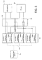
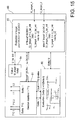
- the figure 3 illustrates the wiring diagram of several DC / DC converters arranged in parallel. These converters 30 are connected on the one hand to a supervisor (ECU) 31 via a CAN bus 32, for example, and on the other hand to a power supply 33 and to a load 34 via wiring modules 35. and 36.
- ECU supervisor
- CAN bus 32 for example
- each DC / DC converter depends on the impedance of the output cables.
- a set of two DC / DC1 and DC / DC2 converters in parallel and means for communicating these converters with each other and with a supervisor (ECU) is considered as a nonlimiting example. using CAN bus.
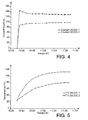
- the curves illustrated on the Figures 4 and 5 present the temperature differences measured as a function of the current imbalances between the first and the second DC / DC converter (DC / DC1 and DC / DC2) cooled in the same way.
- each current difference of an ampere corresponds to a temperature difference of about one degree Celsius.
- the temperature difference (or delta) between these two converters during their life cycles, strongly influences their respective lifetimes.
- the Pareto diagram illustrated on the figure 6 evaluates the lifetimes of these two converters according to their temperature differences (successively for the control card, the power card and the complete converter). It can be deduced from this diagram that the lifetime of the first DC / DC1 converter operating at temperatures 30 ° C higher than those of the second DC / DC2 converter is approximately five times shorter.
- the operating constraints of such DC / DC converters arranged in parallel must therefore include algorithms to ensure their thermal equilibrium in order to optimize and harmonize their service life.
- the solution of the invention is to define a strategy for managing the distribution of the respective currents of these two DC / DC converters according to their internal temperature, knowing that the The temperature of a converter is directly related to the current it provides.
- the objective is to achieve a temperature difference that is below a certain value, for example 10 ° C.
- DC / DC1 and DC / DC2 are considered. identical from a hardware and software point of view connected to a communication system, for example a private or public Controller Area Network (CAN) bus, and controlled by an external supervisor (ECU).
- CAN Controller Area Network
- ECU external supervisor
- a keying makes it possible to define the configuration of each converter: they therefore have two different identifiers after recognition of the keying and are differentiated on the communication network. They are controlled via two different frames.
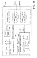
- a software module 40 receives the ON / OFF, U_target, I_max_target and the U_meas and I_meas voltage measurement signals, and delivers PWM_U and PWM_I pulse width modulation signals.
- a hardware module 41 which receives these signals PWM_U and PWM_I, comprises two averaging modules 42 and 43, followed by one of a voltage control loop 44 and the other of a current control loop 45, connected to each other. to a setpoint calculation module 46 followed by a switching power supply 47.
- the figure 8 illustrates the principle of regulation of the software module 50 of a converter DC / DC.
- a software voltage corrector 51 receives a difference signal U target - U meas and delivers the signal PWM_U.
- a software current corrector 52 receives a difference signal I max_ target-Imeas and delivers the signal PWM_I. If voltage is regulated, ie no current limitation is applied, the signal PWM_I is equal to 100% and it is the signal PWM_U which regulates the output voltage.
- the current of a converter remains below the maximum current setpoint to be output I_max_target.
- the thermal balancing is performed in the supervisor (ECU), which is therefore "master".
- the figure 9 illustrates the exchanges of information (currents I1, I2, and temperature T ° C1 and T ° C2 measured) and setpoints (U_target1 and U_target2) made then.
- the DC / DC1 and DC / DC2 converters are completely slave to the supervisor ("double-slave" strategy).
- the intelligence is implemented in it: the distribution of the current is managed by a modification of the voltage setpoints (U_target1 and U_target2), different voltage instructions being then applied to both DC / DC1 and DC / DC2 converters.
- Each converter receives a separate voltage setpoint and returns internal information about the current it provides (I1, I2) and its internal temperature (T ° C1, T ° C2).
- Treatment of the degraded modes (operation at X% of the total power) and a redundancy of the diagnoses are then possible by performing a data processing between the two DC / DC converters and the master ECU.
- the figures 10 and 11 allow to highlight the characteristics of this embodiment in view of a control of two DC / DC converters in parallel respectively without and with thermal balancing strategy.
- a thermal balancing strategy is performed in the master ECU.
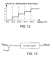
- the figure 12 has the difference delta T (° C) between the two converters and the ordinate the criticality corresponding to this thermal imbalance.
- zone 1 it is possible to manage only the current balancing which is defined as illustrated in FIG. figure 13 .
- a voltage offset (or compensation) Delta_U * (or ⁇ U *) is then applied to the voltage setpoint Delta_U (or ⁇ U) of the converter supplying the least current. This offset is calculated by a slow corrector that converges the measured delta I (AI meas ) with the desired delta I ( ⁇ I target ).
- zone 1 it is desired to obtain substantially equal output currents I1, I2 between the DC / DC converters.
- the difference delta I between the currents I1, I2 delivered by the two DC / DC converters has a set value ⁇ I target (delta I sought) which is equal to zero.
- FIGS. 14A and 14B give two examples of such compensation, which is implemented in the master supervisor.
- Xmv 40 mV
- Ymv 200 mV
- XA 10A
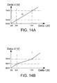
- FIG 14A shows an example in which the Delta U voltage compensation offset is proportional to the delta I current difference.
- Figure 14B presents an example of a lookup table consisting of a mapping which, at a delta I current difference, associates a Delta U compensation offset to be applied to the converter.
- the delta compensation offset U is added to the voltage setpoint U_target_1 of the DC / DC converter 1.
- the delta compensation offset U is added to the voltage setpoint U_target_2 of the DC / DC converter 2.
- Supervisor 60 of the figure 15 can also be implemented with the compensation of the figure 14A .
- zone 2 If you then enter zone 2, you must consider the voltage set point compensation and apply the thermal balancing strategy. Current balancing is then inhibited and heat balancing is applied to "boost" the coldest converter. Contrary to zone 1, in zone 2 no longer attempts to obtain currents I1, 12 equal between the DC / DC converters 1, DC / DC 2, but it is desirable to raise the output current of the converter which has the temperature. low.
- a Delta U voltage offset is applied to the voltage setpoint of this converter, as shown in FIG. figure 16 .
- This offset is calculated by a slow corrector that converges the temperature difference measured between the two converters ( ⁇ T ° C meas ) with the desired temperature difference ( ⁇ T ° C target ).
- the Figures 17A, 17B and 17C illustrate three examples of possible compensation.
- the Figure 17A shows an example in which the Delta U voltage compensation offset is proportional to the delta temperature difference T ° C.
- the Figures 17B, 17C present an example of a table of reference points ("lookup table") consisting of a map which, at a temperature difference delta T ° C, associates a compensation offset Delta U to be applied to the converter.
- the offset offset delta U is added to the voltage set point U_target_1 of the DC converter / DC 1.
- the offset offset delta U is added to the voltage set point U_target_2 of the DC converter / DC 2.
- the sub-embodiments can be combined.
- the first sub-mode is applied when the temperature difference is less than or equal to a predetermined value, for example is in zone 1 (an example of which has previously been given).
- the delta compensation offset U is then a function of the difference in current, for example as represented on the Figures 14A, 14B .
- the second sub-mode is applied when the temperature difference is greater than the predetermined value, for example is in the zones 2, 3, or 4 (examples of which have been previously given).
- the offset compensation delta U is then a function of the temperature difference, for example as represented on the Figures 17A, 17B, 17C .
- the current / thermal balancing strategy is now implemented in the two DC / DC converters.
- the master ECU does not handle the thermal balancing of both converters. It sends a single voltage setpoint U_target to the two converters which self-balance thereafter.
- the thermal balancing strategy is implemented symmetrically in each DC / DC converter. But the adaptation of the voltage setpoint is only in the converter that provides the least current and that one must "boost", that is to say, increase the output current.
- Degraded mode processing (operation at X% of the total power) and redundancy of the diagnostics are also possible by the processing of information passing between the DC / DC converters and the master ECU and between the two DC / DC converters.
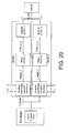
- the figure 20 represents the implementation of this strategy in the DC / DC converters, the principle of current balancing / thermal balancing strategy is the same as that previously described except that the intelligence is now in each of the two DC converters / DC.
- a different control mode 70 is used.
- the regulation of the voltage is now carried out by the software 72.
- This regulation is analogous to that of an electric motor with double loop nested voltage / current.
- the output voltage U meas and the current I meas measured by the DC / DC converter are regulated by means of the signal PWM_I, with a target U target given by the master ECU and an I target setpoint supplied by the voltage controller. of the DC / DC converter master.
- the current balancing / thermal balancing strategy is implemented in the DC / DC converters: the master ECU sends only one voltage setpoint and does not limit the two converters to current.
- the thermal balancing strategy is implemented in the master DC / DC converter, with distribution of the current calculated by this master converter which modulates the current to be discharged by itself and by the slave converter as a function of the temperatures reached.
- the invention is not limited to the examples described.
- the second and third embodiments may have sub-embodiments identical to those of the first embodiment.
Landscapes
- Engineering & Computer Science (AREA)
- Power Engineering (AREA)
- Dc-Dc Converters (AREA)
- Communication Control (AREA)
Claims (17)
- DC/DC-Wandlervorrichtung im Bordnetz eines Fahrzeugs, dadurch gekennzeichnet, dass sie mindestens zwei DC/DC-Wandler (20, 21) enthält, die unterschiedlich, hinsichtlich der Hardware und Software gleich, parallel geschaltet, mit einem Supervisor durch ein Kommunikationssystem verbunden sind, mit symmetrischen Verkabelungen am Eingang und am Ausgang.
- Vorrichtung nach Anspruch 1, wobei jeder Wandler (30) ein Softwaremodul (40) enthält, das von einem Supervisor (31) über einen CAN-Bus einen Ein/Aus-Umwandlungsbefehl (ON/OFF), einen Spannungssollwert (U_target), einen Sollwert eines zu liefernden maximalen Stroms (I_max_target) und Spannungs- (U_meas) und Strommesssignale (I_meas) empfängt, gefolgt von einem Hardwaremodul (41), das zwei Mittelungsmodule (42 und 43) enthält, das eine gefolgt von einem Spannungssteuerkreis (44) und das andere gefolgt von einem Stromsteuerkreis (45), die mit einem Sollwertberechnungsmodul (46) gefolgt von einem Schaltnetzteil (47) verbunden sind, und wobei das Softwaremodul (50) einen Spannungsregler (51) und einen Stromregler (52) enthält.
- Vorrichtung nach Anspruch 1 oder 2, die einen Master-Supervisor und zwei Slave-Wandler enthält.
- Vorrichtung nach Anspruch 1 oder 2, die einen Master-Supervisor und zwei DC/DC-Wandler enthält, die von diesem einen gemeinsamen Spannungssollwert empfangen und miteinander kommunizieren.
- Vorrichtung nach Anspruch 1 oder 2, die einen Master-Supervisor, einen ersten Master-DC/DC-Wandler, der von diesem einen Spannungssollwert empfängt, der die Spannung regelt, und einen zweiten Slave-DC/DC-Wandler enthält, dessen Spannungsregelkreis gesperrt ist, wobei dieser zweite Wandler einen Stromsollwert vom Master-DC/DC-Wandler empfängt und den Strom, den er liefert, und seine Temperatur an ihn zurückschickt.
- Vorrichtung nach einem der vorhergehenden Ansprüche, die die folgenden Module enthält:- ein Modul (61) des Stromausgleichs abhängig von der Temperatur, das verbunden ist:- mit einem Modul (62) zur Ermittlung des Werts einer an einen Wandler anzuwendenden Kompensation (delta U), wobei der Wert von der Differenz (delta I) zwischen den Ausgangsströmen (I1, I2) der Wandler abhängt
 - mit einem Modul (63) zur Ermittlung eines Spannungssollwerts (U_target_1, U_target_2) für jeden der Wandler, das einen Anfangswert (U_tar_init) des Spannungssollwerts, der von einem Rechenmodul (64) geliefert wird, und den von dessen Ermittlungsmodul (62) gelieferten Wert (delta U) empfängt, und wobei der folgende Algorithmus verwendet wird:
if « Boost » DC/DC 1 (U_target_2 = U_tar_init AND U_target_1 = U_tar_init +delta_U) else if « Boost » DC/DC 2 (U_target_1 = U_tar_init AND U_target_2 = U_tar_init +delta_U). - Vorrichtung nach Anspruch 6, die Einrichtungen zum Anwenden eines Spannungsoffsets (delta U) an den Spannungssollwert (U_target_1, U_target_2) des am wenigsten Strom liefernden DC/DC-Wandlers enthält.
- Vorrichtung nach einem der vorhergehenden Ansprüche, die die folgenden Module enthält:- ein Modul (61) zum Ausgleich des Stroms abhängig von der Temperatur, verbunden mit:- einem Modul (62') zur Ermittlung des Werts einer an einen Wandler anzuwendenden Kompensation (delta U), wobei der Wert von der Differenz (delta T°C) zwischen den Temperaturen (T°C 1, T°C 2) der Wandler abhängt
 - einem Modul (63) zur Ermittlung eines Spannungssollwerts (U_target_1, U_target_2) für jeden der Wandler, das einen Anfangswert (U_tar_init) des Spannungssollwerts, der von einem Rechenmodul (64) geliefert wird, und den von dessen Ermittlungsmodul (62) gelieferten Wert (delta U) empfängt, und wobei der folgende Algorithmus verwendet wird:
if « Boost » DC/DC 1 (U_target_2 = U_tar_init AND U_target_1 = U_tar_init +delta_U) else if « Boost » DC/DC 2 (U_target_1 = U_tar_init AND U_target_2 = U_tar_init +delta_U). - Vorrichtung nach Anspruch 8, die Einrichtungen zum Sperren des Stromausgleichs und zum Boosten des kältesten DC/DC-Wandlers enthält.
- Vorrichtung nach einem der vorhergehenden Ansprüche, die Verarbeitungseinrichtungen der Notbetriebe enthält.
- Vorrichtung nach einem der vorhergehenden Ansprüche, die Redundanzeinrichtungen der Diagnosen enthält.
- DC/DC-Umwandlungsverfahren im Bordnetz eines Fahrzeugs, das die Vorrichtung nach einem der vorhergehenden Ansprüche verwendet, das die folgenden Schritte enthält:- einen Schritt des Empfangens in jedem Wandler, von einem Supervisor kommend, eines Spannungssollwerts,- einen Schritt des Sendens durch jeden Wandler von internen Informationen, die den Strom und die innere Temperatur betreffen, und- einen Schritt der Änderung des an mindestens einen DC/DC-Wandler angewendeten Spannungssollwerts abhängig von den Temperaturunterschieden.
- Verfahren nach Anspruch 12, das einen Schritt des Anwendens eines Spannungsoffsets an den Spannungssollwert des DC/DC-Wandlers enthält, der den wenigsten Strom liefert.
- Verfahren nach Anspruch 12, das einen Schritt des Sperrens des Stromausgleichs enthält, und in dem der kälteste DC/DC-Wandler geboostet wird.
- Verfahren nach einem der Ansprüche 12 bis 14, das einen Schritt enthält, in dem jeder Wandler einen anderen Spannungssollwert (U_target_1, U_target_2) vom Supervisor empfängt und an ihn interne Informationen betreffend den von ihm gelieferten Strom (I1, I2) und seine innere Temperatur (T°C1, T°C2) zurückschickt.
- Verfahren nach einem der Ansprüche 12 bis 14, das einen Schritt des Empfangens durch jeden DC/DC-Wandler eines vom Supervisor kommenden gemeinsamen Spannungssollwerts (U_target) und einen Schritt der Kommunikation zwischen ihnen enthält, mit Anpassung des in den den wenigsten Strom liefernden DC/DC-Wandler eingehenden Spannungssollwerts.
- Verfahren nach einem der Ansprüche 12 bis 14, das einen Schritt des Sendens eines Spannungssollwerts (U_target) vom System zu einem Master-Wandler, einen Schritt des Sendens eines Stromsollwerts vom Master-DC/DC-Wandler an einen Slave-Wandler und einen Schritt des Rücksendens durch diesen des Stroms den er liefert und seiner Temperatur enthält.
Applications Claiming Priority (2)
| Application Number | Priority Date | Filing Date | Title |
|---|---|---|---|
| FR1061142A FR2969846B1 (fr) | 2010-12-23 | 2010-12-23 | Dispositif et procede de conversion dc/dc dans le reseau de bord d'un vehicule |
| PCT/FR2011/053122 WO2012085458A2 (fr) | 2010-12-23 | 2011-12-21 | Dispositif et procede de conversion dc/dc dans le reseau de bord d'un vehicule |
Publications (2)
| Publication Number | Publication Date |
|---|---|
| EP2655123A2 EP2655123A2 (de) | 2013-10-30 |
| EP2655123B1 true EP2655123B1 (de) | 2015-04-08 |
Family
ID=45558759
Family Applications (1)
| Application Number | Title | Priority Date | Filing Date |
|---|---|---|---|
| EP11815494.7A Not-in-force EP2655123B1 (de) | 2010-12-23 | 2011-12-21 | Vorrichtung und verfahren zur gleichstromwandlung im bordnetz eines kraftfahrzeuges |
Country Status (4)
| Country | Link |
|---|---|
| EP (1) | EP2655123B1 (de) |
| CN (1) | CN103442933A (de) |
| FR (1) | FR2969846B1 (de) |
| WO (1) | WO2012085458A2 (de) |
Families Citing this family (5)
| Publication number | Priority date | Publication date | Assignee | Title |
|---|---|---|---|---|
| CN103683478B (zh) * | 2013-12-20 | 2015-08-19 | 黑龙江大学 | 单片机用锂电池式短时供电系统及供电的方法 |
| CN103633732B (zh) * | 2013-12-20 | 2015-05-20 | 黑龙江大学 | 单片机用电容式短时供电装置及供电方法 |
| US10131245B2 (en) * | 2016-08-16 | 2018-11-20 | Ford Global Technologies, Llc | Electrified vehicle DC power conversion with distributed control |
| DE102017200232A1 (de) * | 2017-01-10 | 2018-07-12 | Audi Ag | Energiekoppler für ein elektrisch antreibbares Kraftfahrzeug |
| FR3081406B1 (fr) * | 2018-05-24 | 2020-06-19 | Psa Automobiles Sa | Gestion de l’alimentation d’un reseau electrique d’un vehicule automobile hybride |
Family Cites Families (6)
| Publication number | Priority date | Publication date | Assignee | Title |
|---|---|---|---|---|
| JP2004249935A (ja) * | 2003-02-21 | 2004-09-09 | Nissan Motor Co Ltd | 車輌用電源システム |
| JP3976268B2 (ja) * | 2003-11-28 | 2007-09-12 | インターナショナル・ビジネス・マシーンズ・コーポレーション | 電池パック、電気機器、コンピュータ装置、電池の制御方法、電力供給方法、およびプログラム |
| JP4311357B2 (ja) * | 2005-01-27 | 2009-08-12 | 株式会社デンソー | 車両のバッテリ充電状態推定装置 |
| KR101000703B1 (ko) * | 2008-07-08 | 2010-12-10 | 현대자동차주식회사 | 연료전지 하이브리드 차량의 아이들 스탑/해제 제어 방법 |
| JP4525809B2 (ja) * | 2008-07-28 | 2010-08-18 | トヨタ自動車株式会社 | 電源システムおよびそれを備えた車両、ならびに電源システムの制御方法 |
| JP4497238B2 (ja) * | 2008-09-16 | 2010-07-07 | トヨタ自動車株式会社 | 車両制御システム |
-
2010
- 2010-12-23 FR FR1061142A patent/FR2969846B1/fr not_active Expired - Fee Related
-
2011
- 2011-12-21 WO PCT/FR2011/053122 patent/WO2012085458A2/fr unknown
- 2011-12-21 EP EP11815494.7A patent/EP2655123B1/de not_active Not-in-force
- 2011-12-21 CN CN2011800626344A patent/CN103442933A/zh active Pending
Also Published As
| Publication number | Publication date |
|---|---|
| WO2012085458A2 (fr) | 2012-06-28 |
| CN103442933A (zh) | 2013-12-11 |
| EP2655123A2 (de) | 2013-10-30 |
| FR2969846A1 (fr) | 2012-06-29 |
| FR2969846B1 (fr) | 2012-12-21 |
| WO2012085458A3 (fr) | 2012-10-26 |
Similar Documents
| Publication | Publication Date | Title |
|---|---|---|
| EP2655123B1 (de) | Vorrichtung und verfahren zur gleichstromwandlung im bordnetz eines kraftfahrzeuges | |
| EP2079148B1 (de) | Elektrischer Schaltkreis | |
| FR3083929A1 (fr) | Procede de commande en frequence de la tension d'entree d'un convertisseur courant continu-courant continu | |
| FR3003705A1 (fr) | Reseau de bord de vehicule automobile et son procede de gestion ainsi que des moyens d'implementation du procede | |
| WO2013064407A1 (fr) | Dispositif d'equilibrage de charge des elements d'une batterie de puissance | |
| WO2019122696A1 (fr) | Procédé de contrôle d'un convertisseur de courant continu dans un réseau de bord d'un véhicule automobile | |
| FR2977220A1 (fr) | Procede de gestion d'un moteur a combustion interne couple a une machine electrique dans un vehicule automobile | |
| WO2020208326A1 (fr) | Procede et dispositif de controle de l'hybridation d'un aeronef | |
| FR2980651A1 (fr) | Procede de gestion d'un reseau embarque a deux accumulateurs | |
| WO2012085459A1 (fr) | Dispositif et procede de conversion dc/dc dans le reseau de bord d'un vehicule | |
| EP2651007B1 (de) | Stromversorgungssystem | |
| WO2020049237A1 (fr) | Procédé de commande d'un équipement d'alimentation électrique d'un système électrique | |
| FR2966294A1 (fr) | Procede de recharge d'un module supercondensateur d'un vehicule automobile et vehicule automobile correspondant | |
| EP3313687B1 (de) | Verwaltungsverfahren für die temperatur der batterie eines hybridfahrzeuges | |
| WO2020157394A1 (fr) | Procede de pilotage d'un generateur couple a une roue-libre d'un vehicule automobile | |
| FR3082680A1 (fr) | Procede de commande en frequence de la tension d'entree d'un convertisseur courant continu-courant continu | |
| EP3750377B1 (de) | Verfahren zur steuerung der leistungsversorgung von elektrischen heizmitteln eines systems in abhängigkeit von der verfügbaren elektrischen leistung und dem bedarf | |
| EP3300247B1 (de) | Verfahren zur steuerung eines elektromotors eines hybridfahrzeugs | |
| EP3802230B1 (de) | Verwaltung der stromversorgung eines bordnetzes eines hybridfahrzeugs | |
| FR3122535A1 (fr) | Gestion de la polarisation d'une batterie électrique rechargeable pour véhicule automobile | |
| FR3049408A1 (fr) | Procede et systeme de conversion electrique continu-continu entre reseaux d'alimentation electrique relies a une machine electrique tournante de vehicule automobile | |
| FR2970385A1 (fr) | Procede de gestion des ressources en energie electrique d'un vehicule automobile equipe d'une pluralite de consommateurs electriques. | |
| WO2022180310A1 (fr) | Procede et dispositif de controle d'une batterie evitant un emballement thermique | |
| WO2021013539A1 (fr) | Procede de commande, lors des passages de vitesses, des reseaux d'alimentation electrique d'un vehicule hybride equipe d'une boite de vitesse robotisee, ainsi que dispositif de commande, ensemble électrique et véhicule | |
| FR2992489A1 (fr) | Systeme de commande de recharge d'une batterie d'un vehicule automobile en fonctionnement |
Legal Events
| Date | Code | Title | Description |
|---|---|---|---|
| PUAI | Public reference made under article 153(3) epc to a published international application that has entered the european phase |
Free format text: ORIGINAL CODE: 0009012 |
|
| 17P | Request for examination filed |
Effective date: 20130617 |
|
| AK | Designated contracting states |
Kind code of ref document: A2 Designated state(s): AL AT BE BG CH CY CZ DE DK EE ES FI FR GB GR HR HU IE IS IT LI LT LU LV MC MK MT NL NO PL PT RO RS SE SI SK SM TR |
|
| DAX | Request for extension of the european patent (deleted) | ||
| REG | Reference to a national code |
Ref country code: DE Ref legal event code: R079 Ref document number: 602011015574 Country of ref document: DE Free format text: PREVIOUS MAIN CLASS: B60L0011180000 Ipc: H02J0007140000 |
|
| GRAP | Despatch of communication of intention to grant a patent |
Free format text: ORIGINAL CODE: EPIDOSNIGR1 |
|
| RIC1 | Information provided on ipc code assigned before grant |
Ipc: H02J 7/14 20060101AFI20141008BHEP |
|
| INTG | Intention to grant announced |
Effective date: 20141103 |
|
| GRAS | Grant fee paid |
Free format text: ORIGINAL CODE: EPIDOSNIGR3 |
|
| GRAA | (expected) grant |
Free format text: ORIGINAL CODE: 0009210 |
|
| AK | Designated contracting states |
Kind code of ref document: B1 Designated state(s): AL AT BE BG CH CY CZ DE DK EE ES FI FR GB GR HR HU IE IS IT LI LT LU LV MC MK MT NL NO PL PT RO RS SE SI SK SM TR |
|
| REG | Reference to a national code |
Ref country code: GB Ref legal event code: FG4D Free format text: NOT ENGLISH |
|
| REG | Reference to a national code |
Ref country code: CH Ref legal event code: EP |
|
| REG | Reference to a national code |
Ref country code: IE Ref legal event code: FG4D Free format text: LANGUAGE OF EP DOCUMENT: FRENCH |
|
| REG | Reference to a national code |
Ref country code: AT Ref legal event code: REF Ref document number: 721206 Country of ref document: AT Kind code of ref document: T Effective date: 20150515 |
|
| REG | Reference to a national code |
Ref country code: DE Ref legal event code: R096 Ref document number: 602011015574 Country of ref document: DE Effective date: 20150521 |
|
| REG | Reference to a national code |
Ref country code: AT Ref legal event code: MK05 Ref document number: 721206 Country of ref document: AT Kind code of ref document: T Effective date: 20150408 |
|
| REG | Reference to a national code |
Ref country code: NL Ref legal event code: VDEP Effective date: 20150408 |
|
| REG | Reference to a national code |
Ref country code: LT Ref legal event code: MG4D |
|
| PG25 | Lapsed in a contracting state [announced via postgrant information from national office to epo] |
Ref country code: NL Free format text: LAPSE BECAUSE OF FAILURE TO SUBMIT A TRANSLATION OF THE DESCRIPTION OR TO PAY THE FEE WITHIN THE PRESCRIBED TIME-LIMIT Effective date: 20150408 |
|
| PG25 | Lapsed in a contracting state [announced via postgrant information from national office to epo] |
Ref country code: PT Free format text: LAPSE BECAUSE OF FAILURE TO SUBMIT A TRANSLATION OF THE DESCRIPTION OR TO PAY THE FEE WITHIN THE PRESCRIBED TIME-LIMIT Effective date: 20150810 Ref country code: NO Free format text: LAPSE BECAUSE OF FAILURE TO SUBMIT A TRANSLATION OF THE DESCRIPTION OR TO PAY THE FEE WITHIN THE PRESCRIBED TIME-LIMIT Effective date: 20150708 Ref country code: ES Free format text: LAPSE BECAUSE OF FAILURE TO SUBMIT A TRANSLATION OF THE DESCRIPTION OR TO PAY THE FEE WITHIN THE PRESCRIBED TIME-LIMIT Effective date: 20150408 Ref country code: LT Free format text: LAPSE BECAUSE OF FAILURE TO SUBMIT A TRANSLATION OF THE DESCRIPTION OR TO PAY THE FEE WITHIN THE PRESCRIBED TIME-LIMIT Effective date: 20150408 Ref country code: HR Free format text: LAPSE BECAUSE OF FAILURE TO SUBMIT A TRANSLATION OF THE DESCRIPTION OR TO PAY THE FEE WITHIN THE PRESCRIBED TIME-LIMIT Effective date: 20150408 Ref country code: FI Free format text: LAPSE BECAUSE OF FAILURE TO SUBMIT A TRANSLATION OF THE DESCRIPTION OR TO PAY THE FEE WITHIN THE PRESCRIBED TIME-LIMIT Effective date: 20150408 |
|
| PG25 | Lapsed in a contracting state [announced via postgrant information from national office to epo] |
Ref country code: RS Free format text: LAPSE BECAUSE OF FAILURE TO SUBMIT A TRANSLATION OF THE DESCRIPTION OR TO PAY THE FEE WITHIN THE PRESCRIBED TIME-LIMIT Effective date: 20150408 Ref country code: IS Free format text: LAPSE BECAUSE OF FAILURE TO SUBMIT A TRANSLATION OF THE DESCRIPTION OR TO PAY THE FEE WITHIN THE PRESCRIBED TIME-LIMIT Effective date: 20150808 Ref country code: LV Free format text: LAPSE BECAUSE OF FAILURE TO SUBMIT A TRANSLATION OF THE DESCRIPTION OR TO PAY THE FEE WITHIN THE PRESCRIBED TIME-LIMIT Effective date: 20150408 Ref country code: AT Free format text: LAPSE BECAUSE OF FAILURE TO SUBMIT A TRANSLATION OF THE DESCRIPTION OR TO PAY THE FEE WITHIN THE PRESCRIBED TIME-LIMIT Effective date: 20150408 Ref country code: GR Free format text: LAPSE BECAUSE OF FAILURE TO SUBMIT A TRANSLATION OF THE DESCRIPTION OR TO PAY THE FEE WITHIN THE PRESCRIBED TIME-LIMIT Effective date: 20150709 |
|
| REG | Reference to a national code |
Ref country code: FR Ref legal event code: PLFP Year of fee payment: 5 |
|
| REG | Reference to a national code |
Ref country code: DE Ref legal event code: R097 Ref document number: 602011015574 Country of ref document: DE |
|
| PG25 | Lapsed in a contracting state [announced via postgrant information from national office to epo] |
Ref country code: DK Free format text: LAPSE BECAUSE OF FAILURE TO SUBMIT A TRANSLATION OF THE DESCRIPTION OR TO PAY THE FEE WITHIN THE PRESCRIBED TIME-LIMIT Effective date: 20150408 Ref country code: EE Free format text: LAPSE BECAUSE OF FAILURE TO SUBMIT A TRANSLATION OF THE DESCRIPTION OR TO PAY THE FEE WITHIN THE PRESCRIBED TIME-LIMIT Effective date: 20150408 |
|
| PLBE | No opposition filed within time limit |
Free format text: ORIGINAL CODE: 0009261 |
|
| STAA | Information on the status of an ep patent application or granted ep patent |
Free format text: STATUS: NO OPPOSITION FILED WITHIN TIME LIMIT |
|
| PG25 | Lapsed in a contracting state [announced via postgrant information from national office to epo] |
Ref country code: CZ Free format text: LAPSE BECAUSE OF FAILURE TO SUBMIT A TRANSLATION OF THE DESCRIPTION OR TO PAY THE FEE WITHIN THE PRESCRIBED TIME-LIMIT Effective date: 20150408 Ref country code: PL Free format text: LAPSE BECAUSE OF FAILURE TO SUBMIT A TRANSLATION OF THE DESCRIPTION OR TO PAY THE FEE WITHIN THE PRESCRIBED TIME-LIMIT Effective date: 20150408 Ref country code: RO Free format text: LAPSE BECAUSE OF NON-PAYMENT OF DUE FEES Effective date: 20150408 Ref country code: SK Free format text: LAPSE BECAUSE OF FAILURE TO SUBMIT A TRANSLATION OF THE DESCRIPTION OR TO PAY THE FEE WITHIN THE PRESCRIBED TIME-LIMIT Effective date: 20150408 |
|
| 26N | No opposition filed |
Effective date: 20160111 |
|
| PG25 | Lapsed in a contracting state [announced via postgrant information from national office to epo] |
Ref country code: IT Free format text: LAPSE BECAUSE OF FAILURE TO SUBMIT A TRANSLATION OF THE DESCRIPTION OR TO PAY THE FEE WITHIN THE PRESCRIBED TIME-LIMIT Effective date: 20150408 |
|
| PG25 | Lapsed in a contracting state [announced via postgrant information from national office to epo] |
Ref country code: SI Free format text: LAPSE BECAUSE OF FAILURE TO SUBMIT A TRANSLATION OF THE DESCRIPTION OR TO PAY THE FEE WITHIN THE PRESCRIBED TIME-LIMIT Effective date: 20150408 Ref country code: BE Free format text: LAPSE BECAUSE OF NON-PAYMENT OF DUE FEES Effective date: 20151231 |
|
| PG25 | Lapsed in a contracting state [announced via postgrant information from national office to epo] |
Ref country code: MC Free format text: LAPSE BECAUSE OF FAILURE TO SUBMIT A TRANSLATION OF THE DESCRIPTION OR TO PAY THE FEE WITHIN THE PRESCRIBED TIME-LIMIT Effective date: 20150408 Ref country code: LU Free format text: LAPSE BECAUSE OF FAILURE TO SUBMIT A TRANSLATION OF THE DESCRIPTION OR TO PAY THE FEE WITHIN THE PRESCRIBED TIME-LIMIT Effective date: 20151221 |
|
| REG | Reference to a national code |
Ref country code: CH Ref legal event code: PL |
|
| REG | Reference to a national code |
Ref country code: IE Ref legal event code: MM4A |
|
| PG25 | Lapsed in a contracting state [announced via postgrant information from national office to epo] |
Ref country code: CH Free format text: LAPSE BECAUSE OF NON-PAYMENT OF DUE FEES Effective date: 20151231 Ref country code: LI Free format text: LAPSE BECAUSE OF NON-PAYMENT OF DUE FEES Effective date: 20151231 Ref country code: IE Free format text: LAPSE BECAUSE OF NON-PAYMENT OF DUE FEES Effective date: 20151221 |
|
| REG | Reference to a national code |
Ref country code: FR Ref legal event code: PLFP Year of fee payment: 6 |
|
| PG25 | Lapsed in a contracting state [announced via postgrant information from national office to epo] |
Ref country code: HU Free format text: LAPSE BECAUSE OF FAILURE TO SUBMIT A TRANSLATION OF THE DESCRIPTION OR TO PAY THE FEE WITHIN THE PRESCRIBED TIME-LIMIT; INVALID AB INITIO Effective date: 20111221 Ref country code: BG Free format text: LAPSE BECAUSE OF FAILURE TO SUBMIT A TRANSLATION OF THE DESCRIPTION OR TO PAY THE FEE WITHIN THE PRESCRIBED TIME-LIMIT Effective date: 20150408 Ref country code: SM Free format text: LAPSE BECAUSE OF FAILURE TO SUBMIT A TRANSLATION OF THE DESCRIPTION OR TO PAY THE FEE WITHIN THE PRESCRIBED TIME-LIMIT Effective date: 20150408 |
|
| PG25 | Lapsed in a contracting state [announced via postgrant information from national office to epo] |
Ref country code: SE Free format text: LAPSE BECAUSE OF FAILURE TO SUBMIT A TRANSLATION OF THE DESCRIPTION OR TO PAY THE FEE WITHIN THE PRESCRIBED TIME-LIMIT Effective date: 20150408 Ref country code: CY Free format text: LAPSE BECAUSE OF FAILURE TO SUBMIT A TRANSLATION OF THE DESCRIPTION OR TO PAY THE FEE WITHIN THE PRESCRIBED TIME-LIMIT Effective date: 20150408 |
|
| PG25 | Lapsed in a contracting state [announced via postgrant information from national office to epo] |
Ref country code: MT Free format text: LAPSE BECAUSE OF FAILURE TO SUBMIT A TRANSLATION OF THE DESCRIPTION OR TO PAY THE FEE WITHIN THE PRESCRIBED TIME-LIMIT Effective date: 20150408 |
|
| REG | Reference to a national code |
Ref country code: FR Ref legal event code: PLFP Year of fee payment: 7 |
|
| PG25 | Lapsed in a contracting state [announced via postgrant information from national office to epo] |
Ref country code: MK Free format text: LAPSE BECAUSE OF FAILURE TO SUBMIT A TRANSLATION OF THE DESCRIPTION OR TO PAY THE FEE WITHIN THE PRESCRIBED TIME-LIMIT Effective date: 20150408 |
|
| PG25 | Lapsed in a contracting state [announced via postgrant information from national office to epo] |
Ref country code: TR Free format text: LAPSE BECAUSE OF FAILURE TO SUBMIT A TRANSLATION OF THE DESCRIPTION OR TO PAY THE FEE WITHIN THE PRESCRIBED TIME-LIMIT Effective date: 20150408 Ref country code: AL Free format text: LAPSE BECAUSE OF FAILURE TO SUBMIT A TRANSLATION OF THE DESCRIPTION OR TO PAY THE FEE WITHIN THE PRESCRIBED TIME-LIMIT Effective date: 20150408 |
|
| PGFP | Annual fee paid to national office [announced via postgrant information from national office to epo] |
Ref country code: GB Payment date: 20211220 Year of fee payment: 11 Ref country code: FR Payment date: 20211231 Year of fee payment: 11 Ref country code: DE Payment date: 20211210 Year of fee payment: 11 |
|
| REG | Reference to a national code |
Ref country code: DE Ref legal event code: R119 Ref document number: 602011015574 Country of ref document: DE |
|
| GBPC | Gb: european patent ceased through non-payment of renewal fee |
Effective date: 20221221 |
|
| PG25 | Lapsed in a contracting state [announced via postgrant information from national office to epo] |
Ref country code: GB Free format text: LAPSE BECAUSE OF NON-PAYMENT OF DUE FEES Effective date: 20221221 Ref country code: DE Free format text: LAPSE BECAUSE OF NON-PAYMENT OF DUE FEES Effective date: 20230701 |
|
| PG25 | Lapsed in a contracting state [announced via postgrant information from national office to epo] |
Ref country code: FR Free format text: LAPSE BECAUSE OF NON-PAYMENT OF DUE FEES Effective date: 20221231 |