EP2654470B1 - Système de génération d'aérosol ayant des moyens pour gérer la consommation d'un substrat liquide - Google Patents
Système de génération d'aérosol ayant des moyens pour gérer la consommation d'un substrat liquide Download PDFInfo
- Publication number
- EP2654470B1 EP2654470B1 EP11808642.0A EP11808642A EP2654470B1 EP 2654470 B1 EP2654470 B1 EP 2654470B1 EP 11808642 A EP11808642 A EP 11808642A EP 2654470 B1 EP2654470 B1 EP 2654470B1
- Authority
- EP
- European Patent Office
- Prior art keywords
- aerosol
- liquid
- forming substrate
- generating system
- heating element
- Prior art date
- Legal status (The legal status is an assumption and is not a legal conclusion. Google has not performed a legal analysis and makes no representation as to the accuracy of the status listed.)
- Active
Links
- 239000007788 liquid Substances 0.000 title claims description 222
- 239000000758 substrate Substances 0.000 title claims description 114
- 239000000443 aerosol Substances 0.000 title claims description 89
- 238000010438 heat treatment Methods 0.000 claims description 100
- 230000004913 activation Effects 0.000 claims description 17
- 239000000203 mixture Substances 0.000 claims description 16
- 238000009835 boiling Methods 0.000 claims description 14
- 238000000034 method Methods 0.000 claims description 13
- 238000012544 monitoring process Methods 0.000 claims description 8
- 230000001419 dependent effect Effects 0.000 claims description 7
- 238000004590 computer program Methods 0.000 claims description 4
- 239000000463 material Substances 0.000 description 30
- 238000001704 evaporation Methods 0.000 description 14
- 230000008020 evaporation Effects 0.000 description 14
- 230000003247 decreasing effect Effects 0.000 description 12
- 230000000391 smoking effect Effects 0.000 description 11
- 239000003570 air Substances 0.000 description 10
- 229910052751 metal Inorganic materials 0.000 description 10
- 239000002184 metal Substances 0.000 description 10
- -1 aluminium- titanium- zirconium- Chemical compound 0.000 description 9
- 230000009471 action Effects 0.000 description 8
- 238000005485 electric heating Methods 0.000 description 8
- 229910045601 alloy Inorganic materials 0.000 description 7
- 239000000956 alloy Substances 0.000 description 7
- 230000008901 benefit Effects 0.000 description 6
- 238000001514 detection method Methods 0.000 description 6
- 239000002245 particle Substances 0.000 description 6
- 230000000704 physical effect Effects 0.000 description 6
- OKTJSMMVPCPJKN-UHFFFAOYSA-N Carbon Chemical compound [C] OKTJSMMVPCPJKN-UHFFFAOYSA-N 0.000 description 5
- 239000012080 ambient air Substances 0.000 description 5
- 239000000919 ceramic Substances 0.000 description 5
- 239000002131 composite material Substances 0.000 description 4
- 238000009792 diffusion process Methods 0.000 description 4
- 150000002739 metals Chemical class 0.000 description 4
- 238000009834 vaporization Methods 0.000 description 4
- PXHVJJICTQNCMI-UHFFFAOYSA-N Nickel Chemical compound [Ni] PXHVJJICTQNCMI-UHFFFAOYSA-N 0.000 description 3
- 241000208125 Nicotiana Species 0.000 description 3
- 235000002637 Nicotiana tabacum Nutrition 0.000 description 3
- DNIAPMSPPWPWGF-UHFFFAOYSA-N Propylene glycol Chemical compound CC(O)CO DNIAPMSPPWPWGF-UHFFFAOYSA-N 0.000 description 3
- 230000006399 behavior Effects 0.000 description 3
- 239000010439 graphite Substances 0.000 description 3
- 229910002804 graphite Inorganic materials 0.000 description 3
- 239000008263 liquid aerosol Substances 0.000 description 3
- BASFCYQUMIYNBI-UHFFFAOYSA-N platinum Chemical group [Pt] BASFCYQUMIYNBI-UHFFFAOYSA-N 0.000 description 3
- 238000012546 transfer Methods 0.000 description 3
- LFQSCWFLJHTTHZ-UHFFFAOYSA-N Ethanol Chemical compound CCO LFQSCWFLJHTTHZ-UHFFFAOYSA-N 0.000 description 2
- PEDCQBHIVMGVHV-UHFFFAOYSA-N Glycerine Chemical compound OCC(O)CO PEDCQBHIVMGVHV-UHFFFAOYSA-N 0.000 description 2
- XEEYBQQBJWHFJM-UHFFFAOYSA-N Iron Chemical compound [Fe] XEEYBQQBJWHFJM-UHFFFAOYSA-N 0.000 description 2
- UFWIBTONFRDIAS-UHFFFAOYSA-N Naphthalene Chemical compound C1=CC=CC2=CC=CC=C21 UFWIBTONFRDIAS-UHFFFAOYSA-N 0.000 description 2
- 229910018487 Ni—Cr Inorganic materials 0.000 description 2
- 239000004696 Poly ether ether ketone Substances 0.000 description 2
- 239000004698 Polyethylene Substances 0.000 description 2
- 239000004743 Polypropylene Substances 0.000 description 2
- 238000004364 calculation method Methods 0.000 description 2
- 229910052799 carbon Inorganic materials 0.000 description 2
- 229910010293 ceramic material Inorganic materials 0.000 description 2
- 230000008859 change Effects 0.000 description 2
- GUTLYIVDDKVIGB-UHFFFAOYSA-N cobalt atom Chemical compound [Co] GUTLYIVDDKVIGB-UHFFFAOYSA-N 0.000 description 2
- 230000000875 corresponding effect Effects 0.000 description 2
- 230000001186 cumulative effect Effects 0.000 description 2
- 238000013461 design Methods 0.000 description 2
- 238000010586 diagram Methods 0.000 description 2
- 239000000796 flavoring agent Substances 0.000 description 2
- 235000019634 flavors Nutrition 0.000 description 2
- 239000011888 foil Substances 0.000 description 2
- 238000005338 heat storage Methods 0.000 description 2
- 230000007246 mechanism Effects 0.000 description 2
- 229910001092 metal group alloy Inorganic materials 0.000 description 2
- 238000013021 overheating Methods 0.000 description 2
- 239000012071 phase Substances 0.000 description 2
- 239000004033 plastic Substances 0.000 description 2
- 229920003023 plastic Polymers 0.000 description 2
- 229920003223 poly(pyromellitimide-1,4-diphenyl ether) Polymers 0.000 description 2
- 229920002530 polyetherether ketone Polymers 0.000 description 2
- 229920000573 polyethylene Polymers 0.000 description 2
- 229920001155 polypropylene Polymers 0.000 description 2
- 239000000843 powder Substances 0.000 description 2
- 230000004044 response Effects 0.000 description 2
- 230000002441 reversible effect Effects 0.000 description 2
- 150000003839 salts Chemical class 0.000 description 2
- 239000010935 stainless steel Substances 0.000 description 2
- 229910001220 stainless steel Inorganic materials 0.000 description 2
- 239000011232 storage material Substances 0.000 description 2
- GUVRBAGPIYLISA-UHFFFAOYSA-N tantalum atom Chemical compound [Ta] GUVRBAGPIYLISA-UHFFFAOYSA-N 0.000 description 2
- 229910052719 titanium Inorganic materials 0.000 description 2
- 239000010936 titanium Substances 0.000 description 2
- WFKWXMTUELFFGS-UHFFFAOYSA-N tungsten Chemical compound [W] WFKWXMTUELFFGS-UHFFFAOYSA-N 0.000 description 2
- SNICXCGAKADSCV-JTQLQIEISA-N (-)-Nicotine Chemical compound CN1CCC[C@H]1C1=CC=CN=C1 SNICXCGAKADSCV-JTQLQIEISA-N 0.000 description 1
- VYZAMTAEIAYCRO-UHFFFAOYSA-N Chromium Chemical compound [Cr] VYZAMTAEIAYCRO-UHFFFAOYSA-N 0.000 description 1
- 229910001006 Constantan Inorganic materials 0.000 description 1
- ZOKXTWBITQBERF-UHFFFAOYSA-N Molybdenum Chemical compound [Mo] ZOKXTWBITQBERF-UHFFFAOYSA-N 0.000 description 1
- 239000004677 Nylon Substances 0.000 description 1
- 229920003171 Poly (ethylene oxide) Polymers 0.000 description 1
- 239000004642 Polyimide Substances 0.000 description 1
- VYPSYNLAJGMNEJ-UHFFFAOYSA-N Silicium dioxide Chemical compound O=[Si]=O VYPSYNLAJGMNEJ-UHFFFAOYSA-N 0.000 description 1
- VMHLLURERBWHNL-UHFFFAOYSA-M Sodium acetate Chemical compound [Na+].CC([O-])=O VMHLLURERBWHNL-UHFFFAOYSA-M 0.000 description 1
- 229920004933 Terylene® Polymers 0.000 description 1
- ATJFFYVFTNAWJD-UHFFFAOYSA-N Tin Chemical compound [Sn] ATJFFYVFTNAWJD-UHFFFAOYSA-N 0.000 description 1
- RTAQQCXQSZGOHL-UHFFFAOYSA-N Titanium Chemical compound [Ti] RTAQQCXQSZGOHL-UHFFFAOYSA-N 0.000 description 1
- 241000826860 Trapezium Species 0.000 description 1
- QCWXUUIWCKQGHC-UHFFFAOYSA-N Zirconium Chemical compound [Zr] QCWXUUIWCKQGHC-UHFFFAOYSA-N 0.000 description 1
- KCZFLPPCFOHPNI-UHFFFAOYSA-N alumane;iron Chemical compound [AlH3].[Fe] KCZFLPPCFOHPNI-UHFFFAOYSA-N 0.000 description 1
- 239000004411 aluminium Substances 0.000 description 1
- 229910052782 aluminium Inorganic materials 0.000 description 1
- XAGFODPZIPBFFR-UHFFFAOYSA-N aluminium Chemical compound [Al] XAGFODPZIPBFFR-UHFFFAOYSA-N 0.000 description 1
- PNEYBMLMFCGWSK-UHFFFAOYSA-N aluminium oxide Inorganic materials [O-2].[O-2].[O-2].[Al+3].[Al+3] PNEYBMLMFCGWSK-UHFFFAOYSA-N 0.000 description 1
- YXTPWUNVHCYOSP-UHFFFAOYSA-N bis($l^{2}-silanylidene)molybdenum Chemical compound [Si]=[Mo]=[Si] YXTPWUNVHCYOSP-UHFFFAOYSA-N 0.000 description 1
- 238000007664 blowing Methods 0.000 description 1
- 239000012876 carrier material Substances 0.000 description 1
- 230000015556 catabolic process Effects 0.000 description 1
- 239000001913 cellulose Substances 0.000 description 1
- 229920002678 cellulose Polymers 0.000 description 1
- 229920002301 cellulose acetate Polymers 0.000 description 1
- VNNRSPGTAMTISX-UHFFFAOYSA-N chromium nickel Chemical compound [Cr].[Ni] VNNRSPGTAMTISX-UHFFFAOYSA-N 0.000 description 1
- 235000019506 cigar Nutrition 0.000 description 1
- 235000019504 cigarettes Nutrition 0.000 description 1
- 239000010941 cobalt Substances 0.000 description 1
- 229910017052 cobalt Inorganic materials 0.000 description 1
- 150000001875 compounds Chemical class 0.000 description 1
- 239000004020 conductor Substances 0.000 description 1
- 238000011109 contamination Methods 0.000 description 1
- 230000002596 correlated effect Effects 0.000 description 1
- 238000006731 degradation reaction Methods 0.000 description 1
- 238000009795 derivation Methods 0.000 description 1
- 239000010432 diamond Substances 0.000 description 1
- 230000000694 effects Effects 0.000 description 1
- 230000005496 eutectics Effects 0.000 description 1
- 239000002657 fibrous material Substances 0.000 description 1
- 239000006261 foam material Substances 0.000 description 1
- 235000013305 food Nutrition 0.000 description 1
- 239000007789 gas Substances 0.000 description 1
- 239000007792 gaseous phase Substances 0.000 description 1
- 239000011521 glass Substances 0.000 description 1
- 239000003365 glass fiber Substances 0.000 description 1
- 235000011187 glycerol Nutrition 0.000 description 1
- VBJZVLUMGGDVMO-UHFFFAOYSA-N hafnium atom Chemical compound [Hf] VBJZVLUMGGDVMO-UHFFFAOYSA-N 0.000 description 1
- 230000006872 improvement Effects 0.000 description 1
- 229910052500 inorganic mineral Inorganic materials 0.000 description 1
- 239000011810 insulating material Substances 0.000 description 1
- 229910052742 iron Inorganic materials 0.000 description 1
- DALUDRGQOYMVLD-UHFFFAOYSA-N iron manganese Chemical compound [Mn].[Fe] DALUDRGQOYMVLD-UHFFFAOYSA-N 0.000 description 1
- 239000011133 lead Substances 0.000 description 1
- 239000012669 liquid formulation Substances 0.000 description 1
- 239000007769 metal material Substances 0.000 description 1
- 239000010445 mica Substances 0.000 description 1
- 229910052618 mica group Inorganic materials 0.000 description 1
- 239000011707 mineral Substances 0.000 description 1
- 229910021343 molybdenum disilicide Inorganic materials 0.000 description 1
- 229910052759 nickel Inorganic materials 0.000 description 1
- 229960002715 nicotine Drugs 0.000 description 1
- SNICXCGAKADSCV-UHFFFAOYSA-N nicotine Natural products CN1CCCC1C1=CC=CN=C1 SNICXCGAKADSCV-UHFFFAOYSA-N 0.000 description 1
- GUCVJGMIXFAOAE-UHFFFAOYSA-N niobium atom Chemical compound [Nb] GUCVJGMIXFAOAE-UHFFFAOYSA-N 0.000 description 1
- 229920001778 nylon Polymers 0.000 description 1
- 239000012188 paraffin wax Substances 0.000 description 1
- 239000000419 plant extract Substances 0.000 description 1
- 229910052697 platinum Inorganic materials 0.000 description 1
- 229920000728 polyester Polymers 0.000 description 1
- 239000005020 polyethylene terephthalate Substances 0.000 description 1
- 229920001721 polyimide Polymers 0.000 description 1
- 229920000098 polyolefin Polymers 0.000 description 1
- 230000008569 process Effects 0.000 description 1
- 238000005086 pumping Methods 0.000 description 1
- 239000004065 semiconductor Substances 0.000 description 1
- 239000000741 silica gel Substances 0.000 description 1
- 229910002027 silica gel Inorganic materials 0.000 description 1
- 229910010271 silicon carbide Inorganic materials 0.000 description 1
- 229910052709 silver Inorganic materials 0.000 description 1
- 239000004332 silver Substances 0.000 description 1
- 235000017281 sodium acetate Nutrition 0.000 description 1
- 239000001632 sodium acetate Substances 0.000 description 1
- 239000007787 solid Substances 0.000 description 1
- 239000002904 solvent Substances 0.000 description 1
- 229910000601 superalloy Inorganic materials 0.000 description 1
- 239000000725 suspension Substances 0.000 description 1
- 229910052715 tantalum Inorganic materials 0.000 description 1
- 229920001169 thermoplastic Polymers 0.000 description 1
- 239000004416 thermosoftening plastic Substances 0.000 description 1
- 230000001960 triggered effect Effects 0.000 description 1
- 229910052721 tungsten Inorganic materials 0.000 description 1
- 239000010937 tungsten Substances 0.000 description 1
- 230000008016 vaporization Effects 0.000 description 1
- XLYOFNOQVPJJNP-UHFFFAOYSA-N water Substances O XLYOFNOQVPJJNP-UHFFFAOYSA-N 0.000 description 1
- 239000001993 wax Substances 0.000 description 1
- 229910052726 zirconium Inorganic materials 0.000 description 1
Images


Classifications
-
- A—HUMAN NECESSITIES
- A24—TOBACCO; CIGARS; CIGARETTES; SIMULATED SMOKING DEVICES; SMOKERS' REQUISITES
- A24F—SMOKERS' REQUISITES; MATCH BOXES; SIMULATED SMOKING DEVICES
- A24F40/00—Electrically operated smoking devices; Component parts thereof; Manufacture thereof; Maintenance or testing thereof; Charging means specially adapted therefor
- A24F40/50—Control or monitoring
- A24F40/53—Monitoring, e.g. fault detection
-
- A—HUMAN NECESSITIES
- A61—MEDICAL OR VETERINARY SCIENCE; HYGIENE
- A61M—DEVICES FOR INTRODUCING MEDIA INTO, OR ONTO, THE BODY; DEVICES FOR TRANSDUCING BODY MEDIA OR FOR TAKING MEDIA FROM THE BODY; DEVICES FOR PRODUCING OR ENDING SLEEP OR STUPOR
- A61M11/00—Sprayers or atomisers specially adapted for therapeutic purposes
- A61M11/04—Sprayers or atomisers specially adapted for therapeutic purposes operated by the vapour pressure of the liquid to be sprayed or atomised
- A61M11/041—Sprayers or atomisers specially adapted for therapeutic purposes operated by the vapour pressure of the liquid to be sprayed or atomised using heaters
-
- A—HUMAN NECESSITIES
- A24—TOBACCO; CIGARS; CIGARETTES; SIMULATED SMOKING DEVICES; SMOKERS' REQUISITES
- A24F—SMOKERS' REQUISITES; MATCH BOXES; SIMULATED SMOKING DEVICES
- A24F40/00—Electrically operated smoking devices; Component parts thereof; Manufacture thereof; Maintenance or testing thereof; Charging means specially adapted therefor
- A24F40/10—Devices using liquid inhalable precursors
-
- A—HUMAN NECESSITIES
- A24—TOBACCO; CIGARS; CIGARETTES; SIMULATED SMOKING DEVICES; SMOKERS' REQUISITES
- A24F—SMOKERS' REQUISITES; MATCH BOXES; SIMULATED SMOKING DEVICES
- A24F40/00—Electrically operated smoking devices; Component parts thereof; Manufacture thereof; Maintenance or testing thereof; Charging means specially adapted therefor
- A24F40/40—Constructional details, e.g. connection of cartridges and battery parts
- A24F40/42—Cartridges or containers for inhalable precursors
-
- A—HUMAN NECESSITIES
- A24—TOBACCO; CIGARS; CIGARETTES; SIMULATED SMOKING DEVICES; SMOKERS' REQUISITES
- A24F—SMOKERS' REQUISITES; MATCH BOXES; SIMULATED SMOKING DEVICES
- A24F40/00—Electrically operated smoking devices; Component parts thereof; Manufacture thereof; Maintenance or testing thereof; Charging means specially adapted therefor
- A24F40/40—Constructional details, e.g. connection of cartridges and battery parts
- A24F40/44—Wicks
-
- A—HUMAN NECESSITIES
- A24—TOBACCO; CIGARS; CIGARETTES; SIMULATED SMOKING DEVICES; SMOKERS' REQUISITES
- A24F—SMOKERS' REQUISITES; MATCH BOXES; SIMULATED SMOKING DEVICES
- A24F40/00—Electrically operated smoking devices; Component parts thereof; Manufacture thereof; Maintenance or testing thereof; Charging means specially adapted therefor
- A24F40/40—Constructional details, e.g. connection of cartridges and battery parts
- A24F40/46—Shape or structure of electric heating means
-
- A—HUMAN NECESSITIES
- A24—TOBACCO; CIGARS; CIGARETTES; SIMULATED SMOKING DEVICES; SMOKERS' REQUISITES
- A24F—SMOKERS' REQUISITES; MATCH BOXES; SIMULATED SMOKING DEVICES
- A24F40/00—Electrically operated smoking devices; Component parts thereof; Manufacture thereof; Maintenance or testing thereof; Charging means specially adapted therefor
- A24F40/50—Control or monitoring
- A24F40/51—Arrangement of sensors
-
- A—HUMAN NECESSITIES
- A24—TOBACCO; CIGARS; CIGARETTES; SIMULATED SMOKING DEVICES; SMOKERS' REQUISITES
- A24F—SMOKERS' REQUISITES; MATCH BOXES; SIMULATED SMOKING DEVICES
- A24F40/00—Electrically operated smoking devices; Component parts thereof; Manufacture thereof; Maintenance or testing thereof; Charging means specially adapted therefor
- A24F40/50—Control or monitoring
- A24F40/57—Temperature control
-
- A—HUMAN NECESSITIES
- A61—MEDICAL OR VETERINARY SCIENCE; HYGIENE
- A61M—DEVICES FOR INTRODUCING MEDIA INTO, OR ONTO, THE BODY; DEVICES FOR TRANSDUCING BODY MEDIA OR FOR TAKING MEDIA FROM THE BODY; DEVICES FOR PRODUCING OR ENDING SLEEP OR STUPOR
- A61M11/00—Sprayers or atomisers specially adapted for therapeutic purposes
- A61M11/04—Sprayers or atomisers specially adapted for therapeutic purposes operated by the vapour pressure of the liquid to be sprayed or atomised
- A61M11/041—Sprayers or atomisers specially adapted for therapeutic purposes operated by the vapour pressure of the liquid to be sprayed or atomised using heaters
- A61M11/042—Sprayers or atomisers specially adapted for therapeutic purposes operated by the vapour pressure of the liquid to be sprayed or atomised using heaters electrical
-
- A—HUMAN NECESSITIES
- A61—MEDICAL OR VETERINARY SCIENCE; HYGIENE
- A61M—DEVICES FOR INTRODUCING MEDIA INTO, OR ONTO, THE BODY; DEVICES FOR TRANSDUCING BODY MEDIA OR FOR TAKING MEDIA FROM THE BODY; DEVICES FOR PRODUCING OR ENDING SLEEP OR STUPOR
- A61M15/00—Inhalators
- A61M15/0065—Inhalators with dosage or measuring devices
- A61M15/0068—Indicating or counting the number of dispensed doses or of remaining doses
- A61M15/008—Electronic counters
-
- A—HUMAN NECESSITIES
- A61—MEDICAL OR VETERINARY SCIENCE; HYGIENE
- A61M—DEVICES FOR INTRODUCING MEDIA INTO, OR ONTO, THE BODY; DEVICES FOR TRANSDUCING BODY MEDIA OR FOR TAKING MEDIA FROM THE BODY; DEVICES FOR PRODUCING OR ENDING SLEEP OR STUPOR
- A61M15/00—Inhalators
- A61M15/06—Inhaling appliances shaped like cigars, cigarettes or pipes
-
- A—HUMAN NECESSITIES
- A61—MEDICAL OR VETERINARY SCIENCE; HYGIENE
- A61M—DEVICES FOR INTRODUCING MEDIA INTO, OR ONTO, THE BODY; DEVICES FOR TRANSDUCING BODY MEDIA OR FOR TAKING MEDIA FROM THE BODY; DEVICES FOR PRODUCING OR ENDING SLEEP OR STUPOR
- A61M16/00—Devices for influencing the respiratory system of patients by gas treatment, e.g. mouth-to-mouth respiration; Tracheal tubes
- A61M16/0003—Accessories therefor, e.g. sensors, vibrators, negative pressure
- A61M2016/0015—Accessories therefor, e.g. sensors, vibrators, negative pressure inhalation detectors
- A61M2016/0018—Accessories therefor, e.g. sensors, vibrators, negative pressure inhalation detectors electrical
- A61M2016/0021—Accessories therefor, e.g. sensors, vibrators, negative pressure inhalation detectors electrical with a proportional output signal, e.g. from a thermistor
-
- A—HUMAN NECESSITIES
- A61—MEDICAL OR VETERINARY SCIENCE; HYGIENE
- A61M—DEVICES FOR INTRODUCING MEDIA INTO, OR ONTO, THE BODY; DEVICES FOR TRANSDUCING BODY MEDIA OR FOR TAKING MEDIA FROM THE BODY; DEVICES FOR PRODUCING OR ENDING SLEEP OR STUPOR
- A61M2205/00—General characteristics of the apparatus
- A61M2205/33—Controlling, regulating or measuring
- A61M2205/3368—Temperature
-
- A—HUMAN NECESSITIES
- A61—MEDICAL OR VETERINARY SCIENCE; HYGIENE
- A61M—DEVICES FOR INTRODUCING MEDIA INTO, OR ONTO, THE BODY; DEVICES FOR TRANSDUCING BODY MEDIA OR FOR TAKING MEDIA FROM THE BODY; DEVICES FOR PRODUCING OR ENDING SLEEP OR STUPOR
- A61M2205/00—General characteristics of the apparatus
- A61M2205/33—Controlling, regulating or measuring
- A61M2205/3379—Masses, volumes, levels of fluids in reservoirs, flow rates
- A61M2205/3389—Continuous level detection
-
- A—HUMAN NECESSITIES
- A61—MEDICAL OR VETERINARY SCIENCE; HYGIENE
- A61M—DEVICES FOR INTRODUCING MEDIA INTO, OR ONTO, THE BODY; DEVICES FOR TRANSDUCING BODY MEDIA OR FOR TAKING MEDIA FROM THE BODY; DEVICES FOR PRODUCING OR ENDING SLEEP OR STUPOR
- A61M2205/00—General characteristics of the apparatus
- A61M2205/36—General characteristics of the apparatus related to heating or cooling
- A61M2205/3653—General characteristics of the apparatus related to heating or cooling by Joule effect, i.e. electric resistance
-
- A—HUMAN NECESSITIES
- A61—MEDICAL OR VETERINARY SCIENCE; HYGIENE
- A61M—DEVICES FOR INTRODUCING MEDIA INTO, OR ONTO, THE BODY; DEVICES FOR TRANSDUCING BODY MEDIA OR FOR TAKING MEDIA FROM THE BODY; DEVICES FOR PRODUCING OR ENDING SLEEP OR STUPOR
- A61M2205/00—General characteristics of the apparatus
- A61M2205/82—Internal energy supply devices
- A61M2205/8206—Internal energy supply devices battery-operated
Definitions
- the present invention relates to an electrically operated aerosol generating system.
- the present invention relates to an electrically operated aerosol generating system in which the aerosol-forming substrate is liquid and is contained in a liquid storage portion.
- WO 2007/078273 discloses an electric smoking utensil.
- a liquid is stored in a container which communicates with a heater vaporiser, powered by a battery supply, via a series of small apertures.
- the heater is in the form of a spirally wound electric heater mounted on an electrically insulating support.
- the heater is activated by the mouth of a user to switch on the battery power supply. Suction on a mouthpiece by the user causes air to be drawn through holes in the container, over the heater vaporiser, into the mouthpiece and subsequently into the mouth of a user.
- EP 2253233 A discloses an electrically operated smoking system comprising an electric heater for heating an aerosol-forming substrate and electric circuitry configured to monitor the activation of the heater in order to determine when a smoking experience should be ended.
- the electrically operated aerosol generating systems of the prior art do have a number of advantages, but there is still opportunity for improvement in the design, particularly concerning the handling of liquid aerosol-forming substrate stored in the container.
- an electrically operated aerosol generating system for receiving an aerosol-forming substrate, the system comprising: a liquid storage portion for storing liquid aerosol-forming substrate; an electric heater comprising at least one heating element for heating the liquid aerosol-forming substrate; and electric circuitry configured to monitor activation of the electric heater and estimate an amount of liquid aerosol-forming substrate remaining in the liquid storage portion based on the monitored activation.
- the aerosol generating system is arranged to vaporize the aerosol-forming substrate to form the aerosol.
- an aerosol is a suspension of solid particles or liquid droplets in a gas, such as air.
- Activation of the electric heater may be monitored in several ways, for example by monitoring the temperature of the heating element over time, the resistance of the heating element over time, or the power applied to the heater over time, or a combination of two or more of these parameters.
- the electric circuitry is configured to estimate a consumed amount of liquid aerosol-forming substrate, and to subtract the consumed amount from a known initial amount to provide an estimate of liquid aerosol-forming substrate remaining in the liquid storage portion.
- the electric circuitry is configured to monitor activation of the electric heater by monitoring the temperature or resistance of the heating element over time to estimate a consumed amount of aerosol-forming substrate.
- the electric circuitry is configured to estimate a consumed amount of aerosol based on a first equation relating heating element temperature or resistance to aerosol-forming substrate consumption up to a first threshold of temperature or resistance and based on a second equation relating heating element temperature or resistance to aerosol-forming substrate consumption above the first threshold of temperature or resistance.
- the second equation is a linear equation.
- the second equation is dependent on power applied to the heating element.
- the second equation preferably accounts for thermal diffusion through the aerosol forming substrate and any element holding the aerosol forming substrate.
- the first equation is a non-linear equation.
- the first equation is independent of power applied to the heating element.
- the first equation preferably accounts for the enthalpy of vaporisation of the liquid aerosol-forming substrate.
- the value of the first threshold is dependent on the composition of the liquid aerosol forming substrate.
- the first threshold is the boiling point of the liquid aerosol-forming substrate, and more preferably the boiling point of the liquid aerosol-forming substrate at atmospheric pressure.
- the first equation and second equations are also dependent on the composition of the liquid aerosol-forming substrate, as well as the specific properties of the system, such as dimensions and material properties, and the power applied to the heater.
- the first and second equations are therefore preferably empirically derived and stored in the electric circuitry.
- a plurality of different equations may be stored in the electric circuitry for use with different compositions of liquid aerosol-forming substrate and for use at different power levels.
- Providing electric circuitry for determining an amount of liquid aerosol-forming substrate in the liquid storage portion is advantageous for a number of reasons. For example, when the liquid storage portion is empty or nearly empty, insufficient liquid aerosol-forming substrate may be supplied to the electric heater. This may mean that the aerosol created does not have the desired properties, for example, aerosol particle size. This may result in a poor experience for the user. In addition, if it can be determined when the liquid storage portion is empty or nearly empty, it may be possible to inform the user. Then the user can prepare to replace or refill the liquid storage portion.
- the liquid aerosol-forming substrate certain physical properties, for example the vapour pressure or viscosity of the substrate, are chosen in a way to be suitable for use in the aerosol generating system.
- the liquid preferably comprises a tobacco-containing material comprising volatile tobacco flavour compounds which are released from the liquid upon heating.
- the liquid may comprise a non-tobacco material.
- the liquid may include water, ethanol, or other solvents, plant extracts, nicotine solutions, and natural or artificial flavours.
- the liquid further comprises an aerosol former. Examples of suitable aerosol formers are glycerine and propylene glycol.
- An advantage of providing a liquid storage portion is that the liquid in the liquid storage portion is protected from ambient air. In some embodiments, ambient light,cannot enter the liquid storage portion as well, so that the risk of degradation of the liquid is avoided. Moreover, a high level of hygiene can be maintained. If the liquid storage portion is not refillable and the liquid in the liquid storage portion has been used up or has decreased to a predetermined threshold, the liquid storage portion has to be replaced by the user. During such replacement, contamination of the user with the liquid has to be prevented. Alternatively, the liquid storage portion may be refillable. In that case, when the amount of liquid aerosol-forming substrate in the liquid storage portion has decreased to a predetermined threshold, the liquid storage portion may be refilled. Preferably, the liquid storage portion is arranged to hold liquid for a pre-determined number of puffs or heating cycles.
- the electric heater may comprise a single heating element.
- the electric heater may comprise more than one heating elements for example two, or three, or four, or five, or six or more heating elements.
- the heating element or heating elements may be arranged appropriately so as to most effectively heat the liquid aerosol-forming substrate.
- the at least one electric heating element preferably comprises an electrically resistive material.
- Suitable electrically resistive materials include but are not limited to: semiconductors such as doped ceramics, electrically "conductive" ceramics (such as, for example, molybdenum disilicide), carbon, graphite, metals, metal alloys and composite materials made of a ceramic material and a metallic material. Such composite materials may comprise doped or undoped ceramics. Examples of suitable doped ceramics include doped silicon carbides. Examples of suitable metals include titanium, zirconium, tantalum and metals from the platinum group.
- suitable metal alloys include stainless steel, Constantan, nickel-, cobalt-, chromium-, aluminium- titanium- zirconium-, hafnium-, niobium-, molybdenum-, tantalum-, tungsten-, tin-, gallium-, manganese- and iron-containing alloys, and superalloys based on nickel, iron, cobalt, stainless steel, Timetal®, iron-aluminium based alloys and iron-manganese-aluminium based alloys. Timetale is a registered trade mark of Titanium Metals Corporation.
- the electrically resistive material may optionally be embedded in, encapsulated or coated with an insulating material or vice-versa, depending on the kinetics of energy transfer and the external physicochemical properties required.
- the heating element may comprise a metallic etched foil insulated between two layers of an inert material.
- the inert material may comprise Kapton®, all-polyimide or mica foil. Kapton® is a registered trade mark of E.I. du Pont de Nemours and Company.
- the at least one electric heating element may take any suitable form.
- the at least one electric heating element may take the form of a heating blade.
- the at least one electric heating element may take the form of a casing or substrate having different electro-conductive portions, or an electrically resistive metallic tube.
- the liquid storage portion may incorporate a disposable heating element.
- one or more heating needles or rods that run through the liquid aerosol-forming substrate may also be suitable.
- the at least one electric heating element may comprise a flexible sheet of material.
- Other alternatives include a heating wire or filament, for example a Ni-Cr (Nickel-Chromium), platinum, tungsten or alloy wire, or a heating plate.
- the heating element may be deposited in or on a rigid carrier material.
- the at least one electric heating element may comprise a heat sink, or heat reservoir comprising a material capable of absorbing and storing heat and subsequently releasing the heat over time to heat the aerosol-forming substrate.
- the heat sink may be formed of any suitable material, such as a suitable metal or ceramic material.
- the material has a high heat capacity (sensible heat storage material), or is a material capable of absorbing and subsequently releasing heat via a reversible process, such as a high temperature phase change.
- Suitable sensible heat storage materials include silica gel, alumina, carbon, glass mat, glass fibre, minerals, a metal or alloy such as aluminium, silver or lead, and a cellulose material such as paper.
- Other suitable materials which release heat via a reversible phase change include paraffin, sodium acetate, naphthalene, wax, polyethylene oxide, a metal, metal salt, a mixture of eutectic salts or an alloy.
- the heat sink or heat reservoir may be arranged such that it is directly in contact with the liquid aerosol-forming substrate and can transfer the stored heat directly to the substrate.
- the heat stored in the heat sink or heat reservoir may be transferred to the aerosol-forming substrate by means of a heat conductor, such as a metallic tube.
- the at least one heating element may heat the liquid aerosol-forming substrate by means of conduction.
- the heating element may be at least partially in contact with the substrate.
- the heat from the heating element may be conducted to the substrate by means of a heat conductive element.
- the at least one heating element may transfer heat to the incoming ambient air that is drawn through the electrically operated aerosol generating system during use, which in turn heats the aerosol-forming substrate.
- the ambient air may be heated before passing through the aerosol-forming substrate.
- the ambient air may be first drawn through the liquid substrate and then heated.
- the electrically operated aerosol generating system further comprises a capillary wick for conveying the liquid aerosol-forming substrate from the liquid storage portion to the electric heater.
- the capillary wick is arranged to be in contact with liquid in the liquid storage portion.
- the capillary wick extends into the liquid storage portion.
- liquid is transferred from the liquid storage portion to the electric heater by capillary action in the capillary wick.
- the capillary wick has a first end and a second end, the first end extending into the liquid storage portion for contact with liquid therein and the electric heater being arranged to heat liquid in the second end.
- the heater is activated, the liquid at the second end of the capillary wick is vaporized by the at least one heating element of the heater to form the supersaturated vapour.
- the supersaturated vapour is mixed with and carried in the air flow.
- the liquid aerosol-forming substrate has physical properties, including viscosity and surface tension, which allow the liquid to be transported through the capillary wick by capillary action.
- the capillary wick may have a fibrous or spongy structure.
- the capillary wick preferably comprises a bundle of capillaries.
- the capillary wick may comprise a plurality of fibres or threads or other fine bore tubes. The fibres or threads may be generally aligned in the longitudinal direction of the aerosol generating system.
- the capillary wick may comprise sponge-like or foam-like material formed into a rod shape. The rod shape may extend along the longitudinal direction of the aerosol generating system.
- the structure of the wick forms a plurality of small bores or tubes, through which the liquid can be transported by capillary action.
- the capillary wick may comprise any suitable material or combination of materials.
- capillary materials for example a sponge or foam material, ceramic- or graphite-based materials in the form of fibres or sintered powders, foamed metal or plastics material, a fibrous material, for example made of spinned or extruded fibres, such as cellulose acetate, polyester, or bonded polyolefin, polyethylene, terylene or polypropylene fibres, nylon fibres or ceramic.
- the capillary wick may have any suitable capillarity and porosity so as to be used with different liquid physical properties.
- the liquid has physical properties, including but not limited to viscosity, surface tension, density, thermal conductivity, boiling point and vapour pressure, which allow the liquid to be transported through the capillary device by capillary action.
- the at least one heating element is in the form of a heating wire or filament encircling, and optionally supporting, the capillary wick.
- the capillary properties of the wick combined with the properties of the liquid, ensure that, during normal use, the wick is always wet in the heating area. If the wick is dry, there may be overheating.
- Providing a capillary wick may therefore be advantageous as it will allow a measure of this overheating, which in turn can allow a determination of when the amount of liquid aerosol-forming substrate in the liquid storage portion has decreased to a predetermined threshold
- the capillary wick and the heater, and optionally the liquid storage portion, may be removable from the aerosol generating system as a single component.
- the electric circuitry comprises a sensor to detect air flow indicative of a user taking a puff.
- the electric circuitry is arranged to provide an electric current pulse to the electric heater at a predetermined power when the sensor senses a user taking a puff.
- the time-period of the electric current pulse may be pre-set, depending on the amount of liquid desired to be vaporized.
- the electric circuitry is preferably programmable for this purpose.
- the electric circuitry may be arranged to monitor the total time of the time-periods of the electric current pulses and from the monitored total time, predict when the amount of liquid aerosol-forming substrate in the liquid storage portion will decrease to the predetermined threshold.
- the electrically operated aerosol generating system may further comprise a temperature sensor for measuring the temperature of the at least one heating element and the electric circuitry configured to monitor the temperature of the at least one heating element as sensed by the temperature sensor.
- the electric circuitry is arranged to measure the electrical resistance of the at least one heating element, to ascertain the temperature of the heating element from the measured electrical resistance.
- the electric circuitry may be arranged to measure the electrical resistance of the at least one heating element by measuring the current through the at least one heating element and the voltage across the at least one heating element and determining the electrical resistance of the at least one heating element from the measured current and voltage.
- the electric circuitry may comprise a resistor, having a known resistance, in series with the at least one heating element and the electric circuitry may be arranged to measure the current through the at least one heating element by measuring the voltage across the known resistance and determining the current through the at least one heating element from the measured voltage and the known resistance.
- the electric circuitry comprises a manually operable switch for a user to initiate a puff.
- the electric circuitry is arranged to provide an electric current pulse to the electric heater when the user initiates a puff.
- the time-period of the electric current pulse is preferably pre-set depending on the amount of liquid desired to be vaporized.
- the electric circuitry is preferably programmable for this purpose.
- the electric circuitry may be arranged to monitor the total time in which the manually operable switch is activated and, from the monitored total time, estimate an amount of liquid aerosol-forming substrate in the liquid storage portion.
- the electric circuitry may comprise a sensor for detecting the presence of a liquid storage portion.
- the sensor is preferably able to distinguish one liquid storage portion from another liquid storage portion and hence ascertain how much liquid aerosol-forming substrate is contained in the liquid storage portion when full.
- the sensor may also be able to determine the composition of the liquid in the liquid storage portion based on indicia on the liquid storage portion or the shape or size of the liquid storage portion. This, coupled with the monitored activation, may allow the electric circuitry to predict the amount of liquid aerosol-forming substrate in the liquid storage portion during use.
- the electric circuitry is arranged, when the amount of liquid aerosol-forming substrate in the liquid storage portion has decreased to a predetermined threshold, to deactivate the electric heater.
- the electric circuitry may be arranged to deactivate the electric heater by blowing an electrical fuse between the electric heater and an electric power supply.
- the electric circuitry may be arranged to deactivate the electric heater by switching off a switch between the electric heater and an electric power supply. Alternative methods of deactivating the electric heater will be apparent to the skilled person.
- the electric circuitry is arranged, when the amount of liquid aerosol-forming substrate in the liquid storage portion has decreased to a predetermined threshold, to indicate this to a user. This is advantageous because the indication enables the user to refill or replace the liquid storage portion.
- the electrically operated aerosol generating system may comprise a user display.
- the indication may comprise an indication on the user display.
- the indication may comprise an audible indication, or any other suitable type of indication for a user.
- the aerosol generating system may further comprise an electric power supply.
- the aerosol generating system comprises a housing.
- the housing is elongate. If the aerosol generating includes a capillary wick, the longitudinal axis of the capillary wick and the longitudinal axis of the housing may be substantially parallel.
- the housing may comprise a shell and a mouthpiece. In that case, all the components may be contained in either the shell or the mouthpiece.
- the housing includes a removable insert comprising the liquid storage portion, the capillary wick and the heater. In that embodiment, those parts of the aerosol generating system may be removable from the housing as a single component. This may be useful for refilling or replacing the liquid storage portion, for example.
- the housing may comprise any suitable material or combination of materials.
- suitable materials include metals, alloys, plastics or composite materials containing one or more of those materials, or thermoplastics that are suitable for food or pharmaceutical applications, for example polypropylene, polyetheretherketone (PEEK) and polyethylene.
- PEEK polyetheretherketone
- the material is light and non-brittle.
- the aerosol generating system is portable.
- the aerosol generating system may be a smoking system and may have a size comparable to a conventional cigar or cigarette.
- the smoking system may have a total length between approximately 30 mm and approximately 150 mm.
- the smoking system may have an external diameter between approximately 5 mm and approximately 30 mm.
- the electrically operated aerosol generating system is an electrically heated smoking system.
- a method comprising: providing an electrically operated aerosol generating system comprising a liquid storage portion for storing liquid aerosol-forming substrate and an electric heater comprising at least one heating element for heating the liquid aerosol-forming substrate; and monitoring activation of the electric heater and estimating an amount of liquid aerosol-forming substrate remaining in the liquid storage portion based on the monitored activation.
- the step of monitoring activation of the electric heater comprises monitoring the temperature or resistance of the heating element over time to estimate a consumed amount of aerosol-forming substrate.
- the estimate of a consumed amount of aerosol is based on a first equation relating heating element temperature or resistance to aerosol-forming substrate consumption up to a first threshold of temperature or resistance and based on a second equation relating heating element temperature or resistance to aerosol-forming substrate consumption above the first threshold of temperature or resistance.
- the second equation is a linear equation.
- the second equation preferably accounts for thermal diffusion through the aerosol forming substrate or an element holding the aerosol forming substrate.
- the first equation is a non-linear equation.
- the first equation preferably accounts for the enthalpy of vaporisation of the liquid aerosol-forming substrate.
- electric circuitry for an electrically operated aerosol generating system, the electric circuitry being arranged to perform the method of the second aspect of the invention.
- a computer program which, when run on programmable electric circuitry for an electrically operated aerosol generating system, causes the programmable electric circuitry to perform the method of the second aspect of the invention.
- a computer readable storage medium having stored thereon a computer program according to the fourth aspect of the invention.
- FIG. 1 shows one example of an electrically operated aerosol generating system having a liquid storage portion.
- the system is a smoking system.
- the smoking system 100 of Figure 1 comprises a housing 101 having a mouthpiece end 103 and a body end 105.
- an electric power supply in the form of battery 107 and electric circuitry 109.
- a puff detection system 111 is also provided in cooperation with the electric circuitry 109.
- a liquid storage portion in the form of cartridge 113 containing liquid 115, a capillary wick 117 and a heater 119. Note that the heater is only shown schematically in Figure 1 .
- one end of capillary wick 117 extends into cartridge 113 and the other end of capillary wick 117 is surrounded by the heater 119.
- the heater is connected to the electric circuitry via connections 121, which may pass along the outside of cartridge 113 (not shown in Figure 1 ).
- the housing 101 also includes an air inlet 123, an air outlet 125 at the mouthpiece end, and an aerosol-forming chamber 127.
- Liquid 115 is conveyed by capillary action from the cartridge 113 from the end of the wick 117 which extends into the cartridge to the other end of the wick which is surrounded by heater 119.
- the puff detection system 111 senses the puff and activates the heater 119.
- the battery 107 supplies electrical energy to the heater 119 to heat the end of the wick 117 surrounded by the heater.
- the liquid in that end of the wick 117 is vaporized by the heater 119 to create a supersaturated vapour.
- the liquid being vaporized is replaced by further liquid moving along the wick 117 by capillary action. (This is sometimes referred to as "pumping action”.)
- the supersaturated vapour created is mixed with and carried in the air flow from the air inlet 123.
- the vapour condenses to form an inhalable aerosol, which is carried towards the outlet 125 and into the mouth of the user.
- the electric circuitry 109 and puff detection system 111 are preferably programmable.
- the electric circuitry 109 and puff detection system 111 can be used to manage operation of the aerosol generating system. This assists with control of the particle size in the aerosol.
- Figure 1 shows one example of an electrically operated aerosol generating system according to the present invention. Many other examples are possible, however.
- Figure 1 is schematic in nature. In particular, the components shown are not to scale either individually or relative to one another.
- the electrically operated aerosol generating system needs to include or receive a liquid aerosol-forming substrate contained in a liquid storage portion.
- the electrically operated aerosol generating system requires some sort of electric heater having at least one heating element for heating the liquid aerosol-forming substrate.
- the electrically operated aerosol generating system requires electric circuitry for determining an amount of liquid aerosol-forming substrate in the liquid storage portion. This will be described below with reference to Figures 2 to 9 .
- the system does not need to be a smoking system and a puff detection system does not need to be provided. Instead, the system could operate by manual activation, for example the user operating a switch when a puff is taken. For example, the overall shape and size of the housing could be altered. Moreover, the system may not include a capillary wick. In that case, the system may include another mechanism for delivering liquid for vaporization.
- the system does include a capillary wick for conveying the liquid from the liquid storage portion to the at least one heating element.
- the capillary wick can be made from a variety of porous or capillary materials and preferably has a known, pre-defined capillarity. Examples include ceramic- or graphite-based materials in the form of fibres or sintered powders. Wicks of different porosities can be used to accommodate different liquid physical properties such as density, viscosity, surface tension and vapour pressure.
- the wick must be suitable so that the required amount of liquid can be delivered to the heater.
- the heater comprises at least one heating wire or filament extending around the capillary wick.
- the electrically operated aerosol generating system includes electric circuitry for determining an amount of liquid aerosol-forming substrate in the liquid storage portion.
- Embodiments of the invention will now be described with reference to Figures 2 to 9 . The embodiments are based on the example shown in Figure 1 , although they are applicable to other embodiments of electrically operated aerosol generating systems.
- Figure 2 is a plot of the total particle mass (TPM) of aerosol generated in a user puff in a device as shown in Figure 1 , for two different aerosol forming substrates.
- Plot 200 shows the results for Liquid 1
- plot 210 shows the results for Liquid 2
- the plots show the effect on aerosol generation of increasing power to the heater. It can be seen that increasing the power to the heater broadly increases aerosol generation. At very high power aerosol mass reduces, and this can be explained by the evaporated mass remaining in the gaseous phase rather than forming droplets.
- Figure 2 also illustrates that the mass of aerosol generated is also dependent on the composition of the liquid aerosol-forming substrate. For example, different compositions will have different boiling points and different viscosities. Any model to accurately estimate liquid aerosol-forming substrate consumption must therefore account for liquid composition and power applied to the heater.
- FIG. 3 is a plot showing the evaporation rate of a liquid aerosol-forming substrate versus temperature up to its boiling point.
- the experimental data is plotted as diamonds 220.
- a curve 230 drawn with square points, that is fitted to the experimental data 220.
- the constants A and B depend on the liquid composition.
- the rate of evaporation no longer increases in the same manner. At this point further energy from the heating element does not increase the temperature of the liquid. However, as the temperature of the heating element increases beyond the boiling point thermal diffusion through the liquid substrate and more particularly through any medium holding the substrate, in this embodiment the capillary wick, becomes a significant factor. As the heating element temperature rises there is a greater rate of thermal diffusion so more liquid substrate is vaporised.
- Figure 4 is a plot of two different evaporation rate curves as a function of temperature using a wick system as shown in Figure 1 .
- the two curves 240 and 250 correspond to two different amounts of power supplied to the heating element during a puff.
- the first portion below the boiling point of the liquid corresponds to the curve 230 shown in Figure 3 .
- the two curves diverge.
- Curve 240 corresponds to a lower power than curve 250. Both curves show a linear increase in evaporation rate with temperature, but the rate of increase is clearly dependent on power.
- the curves of Figure 4 provide a model that can be used to calculate the evaporation rate of the liquid substrate if the temperature of the heating element and the power applied to the heating element are known.
- the constants A, B, C and D need to be empirically derived and constants C and D must be derived for the different power levels that the system can operate at.
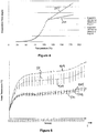
- FIG. 5 is a plot showing five averaged temperature profiles during a puff.
- the temperature, T of the heating element is shown on the y-axis and the puff time t is shown on the x-axis.
- Curve 501 is the median of a first set of puffs, each puff having a 2-second puff duration.
- curve 503 is the median of a second set of puffs
- curve 505 is the median of a third set of puffs
- curve 507 is the median of a fourth set of puffs
- curve 509 is the median over a fifth set of puffs.
- the vertical bars (for example shown at 511) indicate the standard deviation around the median for those puffs.
- the temperature response of the heating element is reasonably stable over curves 501, 503 and 205. That is to say, the standard deviation around the median for the first three sets of puffs is reasonably small.
- the model illustrated in Figure 4 is most accurate during this period when the temperature response is stable. During this period there is always sufficient aerosol-forming substrate being delivered to the heater through the wick. Once the wick begins to dry a different behaviour is observed.
- Figure 6 is an illustration of the temperature profile of a heating element during a puff (averaged over a set of puffs), shown as curve 600 together with the corresponding evaporation rate calculated using the model shown and described with reference to Figure 4 , shown as curve 610.
- the total mass of liquid aerosol-forming substrate evaporated during a puff can be calculated by integrating under the evaporation rate curve 610.
- This integral can be performed by the electric circuitry using the trapezium method for example.
- the result of the integral is shown in Figure 7.
- Figure 7 again shows the temperature profile 600 of a heating element during a puff but also shows the cumulative evaporated mass over the puff as curve 700.
- the total amount of liquid aerosol-forming substrate consumed can be calculated by summing the totals calculated for each puff. This total consumed mass can be subtracted from a known initial mass of liquid in the liquid storage portion to provide an estimate of the amount of liquid aerosol-forming substrate remaining. The amount remaining can be indicated to the user as a meaningful quantity, such as an estimated number of puffs remaining or as a percentage value.
- Determining the amount of liquid aerosol-forming substrate in the liquid storage portion is advantageous because, when the liquid storage portion is empty or nearly empty, insufficient liquid aerosol-forming substrate may be supplied to the heater. This may mean that the aerosol created and inhaled by the user does not have the desired properties, for example, aerosol particle size. This may result in a poor experience for the user.
- the electric circuitry may include a sensor which is able to detect the presence of a liquid storage portion and, moreover, to determine the characteristics of the liquid storage portion including, for example, how much liquid aerosol-forming substrate is contained in the liquid storage portion and the composition of the liquid aerosol-forming substrate. As described in the applicant's pending International application PCT/IB2009/007969 , this may be based on identification information provided on the liquid storage portion. This information, together with information derived from monitoring activation of the heater, allows the electric circuitry to predict the amount of liquid aerosol-forming substrate in the liquid storage portion. Alternatively, the electric circuitry does not need to include a sensor. For example, the amount of liquid aerosol-forming substrate in each liquid storage portion may simply be of only one kind and set at a standard amount.
- the aerosol generating system does not need to include a puff detection system.
- the system could operate by manual activation, for example the user operating a switch when a puff is taken.
- a temperature sensor is provided in the aerosol generating system close to the heating element.
- the electric circuitry can monitor the temperature measured by the temperature sensor and hence determine an amount of liquid in the liquid storage portion as described.
- the amount of liquid in the liquid storage portion is determined by measuring the resistance of the electric heating element. If the heating element has suitable temperature coefficient of resistance characteristics (for example, see equation (5) below), then the resistance may provide a measure of the temperature of the electric heating element.
- Figure 8 is a plot showing the resistance, R of the heating element of the electric heater on the y-axis, versus the temperature, T of the heating element on the x-axis. As can be seen in Figure 8 , as the temperature T of the heating element increases, so does the resistance R. Within a selected range (between temperatures T1 and T2 and resistances R1 and R2 in Figure 4 ), the temperature T and resistance R may be proportional to one another.
- FIG. 9 is a schematic electric circuit diagram showing how the heating element resistance may be measured according to the second embodiment of the invention.
- the heater 901 is connected to a battery 903 which provides a voltage V2.
- the heater resistance to be measured at a particular temperature is R heater .
- an additional resistor 905, with known resistance r is inserted and connected to voltage V1.
- the voltage V1 has an intermediate value between ground and voltage V2 .
- microprocessor 907 to measure the resistance R heater of the heater 901
- the additional resistor 905 whose resistance r is known, is used to determine the current I, again using (1) above.
- the current through the resistor 905 is I and the voltage across the resistor 905 is V1.
- I V 1 r
- the microprocessor 907 can measure V2 and V1, as the aerosol generating system is being used and, knowing the value of r, can determine the heater's resistance at a particular temperature, R heater .
- T R heater ⁇ R 0 + T 0 ⁇ 1 ⁇
- ⁇ the thermal resistivity coefficient of the heating element material
- R 0 the resistance of the heating element at room temperature T 0 .
- An advantage of this embodiment is that no temperature sensor, which can be bulky and expensive, is required.
- a measure of the temperature of the heating element can be derived. This can be used to determine when the amount of liquid in the liquid storage portion has decreased to a threshold and to estimate an absolute amount of aerosol-forming substrate remaining in the liquid storage portion.
- the electric heater may be deactivated. For example, a system may be triggered to render the liquid storage portion unusable.
- the electric circuitry on determining that the amount of liquid aerosol-forming substrate in the liquid storage portion, has decreased to a threshold, may blow an electrical fuse between the at least one heating element of the electric heater and an electric power supply.
- the electrical fuse may be provided as part of a removable component including the liquid storage portion.
- the electric circuitry on determining that the amount of liquid aerosol-forming substrate in the liquid storage portion, has decreased to a threshold, may switch off a switch between the at least one heating element of the electric heater and an electric power supply.
- Alternative methods of deactivating the electric heater are, of course, possible.
- An advantage of deactivating the electric heater is that it is then impossible to use the aerosol generating system. This renders it impossible for a user to inhale an aerosol which does not have the desired properties.
- the user may be advised.
- the electric circuitry on determining that the amount of liquid aerosol-forming substrate in the liquid storage portion, has decreased to a threshold, may indicate this to a user.
- the aerosol generating system includes a user display, it may be indicated to the user, via the user display, that the liquid storage portion is empty or nearly empty.
- an audible sound may indicate to the user that the liquid storage portion is empty or nearly empty.
- Alternative methods of indicating to the user that the liquid storage portion is empty or nearly empty are, of course, possible.
- An advantage of advising the user is that the user is then able to prepare to replace or refill the liquid storage portion.
- the electrically operated aerosol generating system includes electric circuitry for determining when the amount of liquid aerosol-forming substrate in the liquid storage portion has decreased to a predetermined threshold.
- electric circuitry for determining when the amount of liquid aerosol-forming substrate in the liquid storage portion has decreased to a predetermined threshold.
Claims (15)
- Système de génération d'aérosol (100) à fonctionnement électrique pour la réception d'un substrat formant aérosol (115), le système comprenant :une partie de stockage de liquide (113) pour stocker un substrat formant aérosol liquide ;un dispositif de chauffage électrique (119) comprenant au moins un élément de chauffage pour chauffer le substrat formant aérosol liquide ; etun circuit électrique (109) configuré pour commander l'activation du dispositif de chauffage électrique, caractérisé en ce que le circuit électrique est en outre configuré pour estimer une quantité de substrat formant aérosol liquide restant dans la partie de stockage de liquide sur la base de l'activation contrôlée.
- Système de génération d'aérosol à fonctionnement électrique selon la revendication 1, dans lequel le circuit électrique (109) est configuré pour estimer une quantité consommée de substrat formant aérosol liquide (115), et pour soustraire la quantité consommée d'une une quantité initiale connue pour fournir une estimation de substrat formant aérosol liquide restant dans la partie de stockage de liquide.
- Système de génération d'aérosol à fonctionnement électrique selon la revendication 1 ou 2, dans lequel le circuit électrique (109) est configuré pour commander l'activation du dispositif de chauffage électrique (119) en commandant une température ou une résistance de l'élément de chauffage au cours du temps pour estimer une quantité consommée de substrat formant aérosol.
- Système de génération d'aérosol à fonctionnement électrique selon la revendication 3, dans lequel le circuit électrique (109) est configuré pour estimer une quantité consommée d'aérosol sur la base d'une première équation concernant une température ou une résistance de l'élément de chauffage en fonction d'une consommation de substrat formant aérosol jusqu'à un premier seuil de température ou de résistance et sur la base d'une deuxième équation concernant une température ou une résistance de l'élément de chauffage en fonction d'une consommation de substrat formant aérosol au-dessus du premier seuil de température ou de résistance.
- Système de génération d'aérosol à fonctionnement électrique selon la revendication 4, dans lequel la deuxième équation est en fonction de l'énergie appliquée à l'élément de chauffage.
- Système de génération d'aérosol à fonctionnement électrique selon la revendication 4 ou 5, dans lequel la première équation ne dépend pas de l'énergie appliquée à l'élément élément de chauffage.
- Système de génération d'aérosol à fonctionnement électrique selon la revendication 4, 5 ou 6, dans lequel le premier seuil est le point d'ébullition du substrat formant aérosol liquide.
- Système de génération d'aérosol à fonctionnement électrique selon l'une quelconque des revendications 4 à 7, dans lequel les première et deuxième équations sont stockées dans le circuit électrique (109).
- Système de génération d'aérosol à fonctionnement électrique selon la revendication 8, dans lequel une pluralité de première et deuxième équations différentes sont stockées dans le circuit électrique (109) pour une utilisation avec des compositions différentes de substrat formant aérosol liquide et pour une utilisation à différents niveaux d'énergie.
- Système de génération d'aérosol à fonctionnement électrique selon une quelconque revendication précédente, dans lequel le circuit électrique (109) est disposé pour mesurer la résistance électrique de l'au moins un élément de chauffage (119), pour établir la température de l'élément de chauffage à partir de la résistance électrique mesurée.
- Système de génération d'aérosol à fonctionnement électrique selon une quelconque revendication précédente, comprenant en outre une mèche capillaire (117) pour transporter le substrat formant aérosol liquide depuis la partie de stockage de liquide jusqu'au dispositif de chauffage électrique.
- Procédé comprenant :la fourniture d'un système de génération d'aérosol (100) à fonctionnement électrique comprenant une partie de stockage de liquide (113) pour stocker un substrat formant aérosol liquide (115) et un dispositif de chauffage électrique (119) comprenant au moins un élément de chauffage pour chauffer le substrat formant aérosol liquide ; etle commande de l'activation du dispositif de chauffage électrique, caractérisé par l'estimation d'une quantité de substrat formant aérosol liquide restant dans la partie de stockage de liquide sur la base de l'activation contrôlée.
- Circuit électrique pour un système de génération d'aérosol à fonctionnement électrique, le système de génération d'aérosol à fonctionnement électrique comprenant une partie de stockage de liquide (113) pour stocker un substrat formant aérosol liquide (115) et un dispositif de chauffage électrique (119) comprenant au moins un élément de chauffage pour chauffer le substrat formant aérosol liquide, le circuit électrique étant disposé pour exécuter le procédé selon la revendication 12.
- Programme informatique qui fait que, lorsqu'il fonctionne sur un circuit électrique programmable pour un système de génération d'aérosol à fonctionnement électrique, le système de génération d'aérosol à fonctionnement électrique comprenant une partie de stockage de liquide (113) pour stocker un substrat formant aérosol liquide (115) et un dispositif de chauffage électrique (119) comprenant au moins un élément de chauffage pour chauffer le substrat formant aérosol liquide, le circuit électrique programmable exécute le procédé selon la revendication 12.
- Support de stockage lisible par ordinateur sur lequel est stocké un programme informatique selon la revendication 14.
Priority Applications (2)
| Application Number | Priority Date | Filing Date | Title |
|---|---|---|---|
| PL11808642T PL2654470T3 (pl) | 2010-12-24 | 2011-12-22 | Układ wytwarzania aerozolu posiadający środki obsługujące zużywanie ciekłego substratu |
| EP11808642.0A EP2654470B1 (fr) | 2010-12-24 | 2011-12-22 | Système de génération d'aérosol ayant des moyens pour gérer la consommation d'un substrat liquide |
Applications Claiming Priority (3)
| Application Number | Priority Date | Filing Date | Title |
|---|---|---|---|
| EP10252234A EP2468116A1 (fr) | 2010-12-24 | 2010-12-24 | Système de génération d'aérosol disposant de supports pour gérer la consommation d'un substrat liquide |
| PCT/EP2011/073795 WO2012085207A1 (fr) | 2010-12-24 | 2011-12-22 | Système de génération d'aérosol ayant des moyens pour gérer la consommation d'un substrat liquide |
| EP11808642.0A EP2654470B1 (fr) | 2010-12-24 | 2011-12-22 | Système de génération d'aérosol ayant des moyens pour gérer la consommation d'un substrat liquide |
Publications (2)
| Publication Number | Publication Date |
|---|---|
| EP2654470A1 EP2654470A1 (fr) | 2013-10-30 |
| EP2654470B1 true EP2654470B1 (fr) | 2017-03-01 |
Family
ID=43875674
Family Applications (2)
| Application Number | Title | Priority Date | Filing Date |
|---|---|---|---|
| EP10252234A Ceased EP2468116A1 (fr) | 2010-12-24 | 2010-12-24 | Système de génération d'aérosol disposant de supports pour gérer la consommation d'un substrat liquide |
| EP11808642.0A Active EP2654470B1 (fr) | 2010-12-24 | 2011-12-22 | Système de génération d'aérosol ayant des moyens pour gérer la consommation d'un substrat liquide |
Family Applications Before (1)
| Application Number | Title | Priority Date | Filing Date |
|---|---|---|---|
| EP10252234A Ceased EP2468116A1 (fr) | 2010-12-24 | 2010-12-24 | Système de génération d'aérosol disposant de supports pour gérer la consommation d'un substrat liquide |
Country Status (21)
| Country | Link |
|---|---|
| US (1) | US9763476B2 (fr) |
| EP (2) | EP2468116A1 (fr) |
| JP (1) | JP5959532B2 (fr) |
| KR (2) | KR101931832B1 (fr) |
| CN (1) | CN103338664B (fr) |
| AU (1) | AU2011347189B2 (fr) |
| BR (1) | BR112013018323B1 (fr) |
| CA (1) | CA2822728C (fr) |
| CO (1) | CO6761317A2 (fr) |
| EA (1) | EA029524B1 (fr) |
| ES (1) | ES2618906T3 (fr) |
| IL (1) | IL226909A (fr) |
| MX (1) | MX343872B (fr) |
| MY (1) | MY166116A (fr) |
| NZ (1) | NZ611897A (fr) |
| PL (1) | PL2654470T3 (fr) |
| PT (1) | PT2654470T (fr) |
| SG (1) | SG191276A1 (fr) |
| UA (1) | UA110631C2 (fr) |
| WO (1) | WO2012085207A1 (fr) |
| ZA (1) | ZA201304320B (fr) |
Cited By (1)
| Publication number | Priority date | Publication date | Assignee | Title |
|---|---|---|---|---|
| US11528943B2 (en) | 2017-10-24 | 2022-12-20 | Japan Tobacco Inc. | Aerosol generating apparatus and method and program for actuating the same |
Families Citing this family (227)
| Publication number | Priority date | Publication date | Assignee | Title |
|---|---|---|---|---|
| US10244793B2 (en) | 2005-07-19 | 2019-04-02 | Juul Labs, Inc. | Devices for vaporization of a substance |
| US7726320B2 (en) | 2006-10-18 | 2010-06-01 | R. J. Reynolds Tobacco Company | Tobacco-containing smoking article |
| WO2008112661A2 (fr) | 2007-03-09 | 2008-09-18 | Alexza Pharmaceuticals, Inc. | Unité chauffante à utiliser dans un dispositif d'administration de médicament |
| EP2100525A1 (fr) * | 2008-03-14 | 2009-09-16 | Philip Morris Products S.A. | Système de génération d'aérosol à chauffage électrique et procédé |
| US9259035B2 (en) | 2010-05-15 | 2016-02-16 | R. J. Reynolds Tobacco Company | Solderless personal vaporizing inhaler |
| US9095175B2 (en) | 2010-05-15 | 2015-08-04 | R. J. Reynolds Tobacco Company | Data logging personal vaporizing inhaler |
| US10159278B2 (en) | 2010-05-15 | 2018-12-25 | Rai Strategic Holdings, Inc. | Assembly directed airflow |
| US10136672B2 (en) | 2010-05-15 | 2018-11-27 | Rai Strategic Holdings, Inc. | Solderless directly written heating elements |
| US9999250B2 (en) | 2010-05-15 | 2018-06-19 | Rai Strategic Holdings, Inc. | Vaporizer related systems, methods, and apparatus |
| US8757147B2 (en) | 2010-05-15 | 2014-06-24 | Minusa Holdings Llc | Personal vaporizing inhaler with internal light source |
| US9861772B2 (en) | 2010-05-15 | 2018-01-09 | Rai Strategic Holdings, Inc. | Personal vaporizing inhaler cartridge |
| US9743691B2 (en) | 2010-05-15 | 2017-08-29 | Rai Strategic Holdings, Inc. | Vaporizer configuration, control, and reporting |
| PL2982255T3 (pl) | 2010-08-24 | 2019-11-29 | Jt Int Sa | Urządzenie do wdychania z kontrolowanym użyciem substancji |
| EP2468117A1 (fr) | 2010-12-24 | 2012-06-27 | Philip Morris Products S.A. | Système de génération d'aérosol disposant de supports pour déterminer la déplétion d'un substrat liquide |
| EP2468118A1 (fr) | 2010-12-24 | 2012-06-27 | Philip Morris Products S.A. | Système de génération d'aérosol afin de désactiver un consommable |
| AT510837B1 (de) | 2011-07-27 | 2012-07-15 | Helmut Dr Buchberger | Inhalatorkomponente |
| US8528569B1 (en) | 2011-06-28 | 2013-09-10 | Kyle D. Newton | Electronic cigarette with liquid reservoir |
| US9078473B2 (en) | 2011-08-09 | 2015-07-14 | R.J. Reynolds Tobacco Company | Smoking articles and use thereof for yielding inhalation materials |
| ES2621888T3 (es) | 2011-08-16 | 2017-07-05 | Pax Labs, Inc. | Dispositivo de vaporización electrónica a baja temperatura |
| US9854839B2 (en) | 2012-01-31 | 2018-01-02 | Altria Client Services Llc | Electronic vaping device and method |
| US20130255702A1 (en) | 2012-03-28 | 2013-10-03 | R.J. Reynolds Tobacco Company | Smoking article incorporating a conductive substrate |
| US10004259B2 (en) | 2012-06-28 | 2018-06-26 | Rai Strategic Holdings, Inc. | Reservoir and heater system for controllable delivery of multiple aerosolizable materials in an electronic smoking article |
| US9814262B2 (en) * | 2012-07-11 | 2017-11-14 | Sis Resources, Ltd. | Hot-wire control for an electronic cigarette |
| GB2504074A (en) * | 2012-07-16 | 2014-01-22 | Nicoventures Holdings Ltd | Electronic cigarette |
| US10517530B2 (en) | 2012-08-28 | 2019-12-31 | Juul Labs, Inc. | Methods and devices for delivering and monitoring of tobacco, nicotine, or other substances |
| US8881737B2 (en) * | 2012-09-04 | 2014-11-11 | R.J. Reynolds Tobacco Company | Electronic smoking article comprising one or more microheaters |
| US8910639B2 (en) | 2012-09-05 | 2014-12-16 | R. J. Reynolds Tobacco Company | Single-use connector and cartridge for a smoking article and related method |
| US10117460B2 (en) | 2012-10-08 | 2018-11-06 | Rai Strategic Holdings, Inc. | Electronic smoking article and associated method |
| US9854841B2 (en) | 2012-10-08 | 2018-01-02 | Rai Strategic Holdings, Inc. | Electronic smoking article and associated method |
| CN102940313B (zh) | 2012-11-13 | 2015-04-01 | 卓尔悦(常州)电子科技有限公司 | 电子烟的智能控制器及方法 |
| US10034988B2 (en) | 2012-11-28 | 2018-07-31 | Fontem Holdings I B.V. | Methods and devices for compound delivery |
| US9210738B2 (en) * | 2012-12-07 | 2015-12-08 | R.J. Reynolds Tobacco Company | Apparatus and method for winding a substantially continuous heating element about a substantially continuous wick |
| US8910640B2 (en) * | 2013-01-30 | 2014-12-16 | R.J. Reynolds Tobacco Company | Wick suitable for use in an electronic smoking article |
| DE202013100606U1 (de) * | 2013-02-11 | 2013-02-27 | Ewwk Ug | Elektronische Zigarette oder Pfeife |
| US10031183B2 (en) | 2013-03-07 | 2018-07-24 | Rai Strategic Holdings, Inc. | Spent cartridge detection method and system for an electronic smoking article |
| US20140261486A1 (en) * | 2013-03-12 | 2014-09-18 | R.J. Reynolds Tobacco Company | Electronic smoking article having a vapor-enhancing apparatus and associated method |
| US20140261487A1 (en) | 2013-03-14 | 2014-09-18 | R. J. Reynolds Tobacco Company | Electronic smoking article with improved storage and transport of aerosol precursor compositions |
| US9918495B2 (en) | 2014-02-28 | 2018-03-20 | Rai Strategic Holdings, Inc. | Atomizer for an aerosol delivery device and related input, aerosol production assembly, cartridge, and method |
| US9277770B2 (en) | 2013-03-14 | 2016-03-08 | R. J. Reynolds Tobacco Company | Atomizer for an aerosol delivery device formed from a continuously extending wire and related input, cartridge, and method |
| US9609893B2 (en) | 2013-03-15 | 2017-04-04 | Rai Strategic Holdings, Inc. | Cartridge and control body of an aerosol delivery device including anti-rotation mechanism and related method |
| US9220302B2 (en) | 2013-03-15 | 2015-12-29 | R.J. Reynolds Tobacco Company | Cartridge for an aerosol delivery device and method for assembling a cartridge for a smoking article |
| US10279934B2 (en) | 2013-03-15 | 2019-05-07 | Juul Labs, Inc. | Fillable vaporizer cartridge and method of filling |
| US9423152B2 (en) | 2013-03-15 | 2016-08-23 | R. J. Reynolds Tobacco Company | Heating control arrangement for an electronic smoking article and associated system and method |
| US9491974B2 (en) | 2013-03-15 | 2016-11-15 | Rai Strategic Holdings, Inc. | Heating elements formed from a sheet of a material and inputs and methods for the production of atomizers |
| WO2014182736A1 (fr) | 2013-05-06 | 2014-11-13 | Ploom, Inc. | Formulations de sel de nicotine pour pulvérisateurs et procédés correspondants |
| US20140338685A1 (en) | 2013-05-20 | 2014-11-20 | Sis Resources, Ltd. | Burning prediction and communications for an electronic cigarette |
| WO2014201432A1 (fr) | 2013-06-14 | 2014-12-18 | Ploom, Inc. | Éléments chauffants multiples avec matériaux vaporisables distincts dans un dispositif de vaporisation électrique |
| WO2014205748A1 (fr) * | 2013-06-27 | 2014-12-31 | 瑞吉高新科技股份有限公司 | Cigarette électronique |
| US11229239B2 (en) | 2013-07-19 | 2022-01-25 | Rai Strategic Holdings, Inc. | Electronic smoking article with haptic feedback |
| EP4218455A1 (fr) * | 2013-07-30 | 2023-08-02 | Altria Client Services LLC | Appareil de génération de vapeur aromatisée |
| CN113786010A (zh) * | 2013-08-20 | 2021-12-14 | Vmr产品有限公司 | 蒸发器 |
| US10172387B2 (en) | 2013-08-28 | 2019-01-08 | Rai Strategic Holdings, Inc. | Carbon conductive substrate for electronic smoking article |
| US10194693B2 (en) | 2013-09-20 | 2019-02-05 | Fontem Holdings 1 B.V. | Aerosol generating device |
| WO2015066927A1 (fr) * | 2013-11-11 | 2015-05-14 | 吉瑞高新科技股份有限公司 | Atomiseur de cigarette électronique, cigarette électronique et son procédé d'assemblage |
| US10980273B2 (en) | 2013-11-12 | 2021-04-20 | VMR Products, LLC | Vaporizer, charger and methods of use |
| PL3071273T3 (pl) | 2013-11-21 | 2021-06-28 | Fontem Holdings 4 B.V. | Urządzenie, sposób i system do rejestrowania danych dotyczących palenia |
| US9839237B2 (en) | 2013-11-22 | 2017-12-12 | Rai Strategic Holdings, Inc. | Reservoir housing for an electronic smoking article |
| JP6877141B2 (ja) | 2013-12-05 | 2021-05-26 | ジュール・ラブズ・インコーポレイテッドJuul Labs, Inc. | エアロゾル装置のためのニコチン液体製剤及びその方法 |
| US9549573B2 (en) | 2013-12-23 | 2017-01-24 | Pax Labs, Inc. | Vaporization device systems and methods |
| USD842536S1 (en) | 2016-07-28 | 2019-03-05 | Juul Labs, Inc. | Vaporizer cartridge |
| US10076139B2 (en) | 2013-12-23 | 2018-09-18 | Juul Labs, Inc. | Vaporizer apparatus |
| AT16039U3 (de) * | 2013-12-23 | 2019-02-15 | Juul Labs Uk Holdco Ltd | Systeme für eine verdampfungsvorrichtung |
| USD825102S1 (en) | 2016-07-28 | 2018-08-07 | Juul Labs, Inc. | Vaporizer device with cartridge |
| US20160366947A1 (en) | 2013-12-23 | 2016-12-22 | James Monsees | Vaporizer apparatus |
| US10159282B2 (en) | 2013-12-23 | 2018-12-25 | Juul Labs, Inc. | Cartridge for use with a vaporizer device |
| US10058129B2 (en) * | 2013-12-23 | 2018-08-28 | Juul Labs, Inc. | Vaporization device systems and methods |
| DE202014011297U1 (de) | 2013-12-23 | 2019-02-13 | Juul Labs Uk Holdco Limited | Systeme für eine Verdampfungsvorrichtung |
| US9974334B2 (en) | 2014-01-17 | 2018-05-22 | Rai Strategic Holdings, Inc. | Electronic smoking article with improved storage of aerosol precursor compositions |
| CN203618789U (zh) * | 2014-01-26 | 2014-06-04 | 惠州市吉瑞科技有限公司 | 一种电子烟的电池组件及一种电子烟 |
| GB201401520D0 (en) * | 2014-01-29 | 2014-03-12 | Batmark Ltd | Aerosol-forming member |
| US10575558B2 (en) | 2014-02-03 | 2020-03-03 | Rai Strategic Holdings, Inc. | Aerosol delivery device comprising multiple outer bodies and related assembly method |
| US10238764B2 (en) | 2014-08-19 | 2019-03-26 | Vapium Inc. | Aromatherapy vaporization device |
| US11065402B2 (en) | 2014-02-04 | 2021-07-20 | Gseh Holistic, Inc. | Aromatherapy vaporization device |
| TWI828016B (zh) | 2014-02-06 | 2024-01-01 | 美商尤爾實驗室有限公司 | 用於產生可吸入蒸汽之電子裝置及包括該電子裝置之系統及套件 |
| US10709173B2 (en) | 2014-02-06 | 2020-07-14 | Juul Labs, Inc. | Vaporizer apparatus |
| US20150224268A1 (en) | 2014-02-07 | 2015-08-13 | R.J. Reynolds Tobacco Company | Charging Accessory Device for an Aerosol Delivery Device and Related System, Method, Apparatus, and Computer Program Product for Providing Interactive Services for Aerosol Delivery Devices |
| JP6438967B2 (ja) * | 2014-02-10 | 2018-12-19 | フィリップ・モーリス・プロダクツ・ソシエテ・アノニム | 流体透過性ヒーター組立品を持つエアロゾル発生システム |
| US9833019B2 (en) | 2014-02-13 | 2017-12-05 | Rai Strategic Holdings, Inc. | Method for assembling a cartridge for a smoking article |
| FR3017954B1 (fr) * | 2014-02-21 | 2016-12-02 | Smokio | Cigarette electronique |
| US10201181B2 (en) | 2014-02-28 | 2019-02-12 | Beyond Twenty Ltd. | Electronic vaporiser system |
| US10091839B2 (en) | 2014-02-28 | 2018-10-02 | Beyond Twenty Ltd. | Electronic vaporiser system |
| GB201413019D0 (en) | 2014-02-28 | 2014-09-03 | Beyond Twenty Ltd | Beyond 1B |
| US11085550B2 (en) | 2014-02-28 | 2021-08-10 | Ayr Ltd. | Electronic vaporiser system |
| US10081531B2 (en) | 2014-02-28 | 2018-09-25 | Beyond Twenty Ltd. | Electronic vaporiser system |
| US10588176B2 (en) | 2014-02-28 | 2020-03-10 | Ayr Ltd. | Electronic vaporiser system |
| US10136674B2 (en) | 2014-02-28 | 2018-11-27 | Beyond Twenty Ltd. | Electronic vaporiser system |
| US9839238B2 (en) | 2014-02-28 | 2017-12-12 | Rai Strategic Holdings, Inc. | Control body for an electronic smoking article |
| US9597466B2 (en) | 2014-03-12 | 2017-03-21 | R. J. Reynolds Tobacco Company | Aerosol delivery system and related method, apparatus, and computer program product for providing control information to an aerosol delivery device via a cartridge |
| US11696604B2 (en) | 2014-03-13 | 2023-07-11 | Rai Strategic Holdings, Inc. | Aerosol delivery device and related method and computer program product for controlling an aerosol delivery device based on input characteristics |
| MX2016012118A (es) * | 2014-03-19 | 2017-01-19 | Philip Morris Products Sa | Dispositivos generadores de aerosol que incorporan una mecha y un elemento de calentamiento entrecruzados. |
| GB201407426D0 (en) * | 2014-04-28 | 2014-06-11 | Batmark Ltd | Aerosol forming component |
| RU2674714C2 (ru) * | 2014-04-30 | 2018-12-12 | Филип Моррис Продактс С.А. | Контейнер, имеющий нагреватель, для образующего аэрозоль устройства, и образующее аэрозоль устройство |
| US11478021B2 (en) | 2014-05-16 | 2022-10-25 | Juul Labs, Inc. | Systems and methods for aerosolizing a vaporizable material |
| TWI635897B (zh) * | 2014-05-21 | 2018-09-21 | 瑞士商菲利浦莫里斯製品股份有限公司 | 氣溶膠形成基材及氣溶膠傳遞系統 |
| GB201410171D0 (en) | 2014-06-09 | 2014-07-23 | Nicoventures Holdings Ltd | Electronic vapour provision system |
| US10888119B2 (en) | 2014-07-10 | 2021-01-12 | Rai Strategic Holdings, Inc. | System and related methods, apparatuses, and computer program products for controlling operation of a device based on a read request |
| PT3166426T (pt) * | 2014-07-11 | 2018-12-24 | Philip Morris Products Sa | Sistema gerador de aerossol compreendendo a deteção de cartuchos |
| RU2683656C2 (ru) * | 2014-07-11 | 2019-04-01 | Филип Моррис Продактс С.А. | Образующая аэрозоль система, содержащая съемный нагреватель |
| US11350669B2 (en) * | 2014-08-22 | 2022-06-07 | Njoy, Llc | Heating control for vaporizing device |
| KR102627987B1 (ko) * | 2014-12-05 | 2024-01-22 | 쥴 랩스, 인크. | 교정된 투여량 제어 |
| GB2533135B (en) | 2014-12-11 | 2020-11-11 | Nicoventures Holdings Ltd | Aerosol provision systems |
| EA034092B1 (ru) * | 2014-12-18 | 2019-12-26 | ДжейТи ИНТЕРНЭШНЛ СА | Контейнер для устройства, генерирующего аэрозоль |
| GB201423312D0 (en) | 2014-12-29 | 2015-02-11 | British American Tobacco Co | Heating device for apparatus for heating smokable material and method of manufacture |
| GB201423317D0 (en) | 2014-12-29 | 2015-02-11 | British American Tobacco Co | Apparatus for heating smokable material |
| GB201423318D0 (en) | 2014-12-29 | 2015-02-11 | British American Tobacco Co | Cartridge for use with apparatus for heating smokable material |
| CN204540815U (zh) * | 2015-01-16 | 2015-08-12 | 惠州市吉瑞科技有限公司 | 一种自动控制雾化功率的电子烟 |
| US10321711B2 (en) * | 2015-01-29 | 2019-06-18 | Rai Strategic Holdings, Inc. | Proximity detection for an aerosol delivery device |
| AU2015381215B2 (en) * | 2015-02-05 | 2021-05-13 | Silvio BELLINVIA | Capillary proximity heater with high energy saving equipped upstream of a microfiltration apparatus for the elimination of calcareuos particles present in fluids and downstream of a nozzle or closed circuit |
| US20210172650A1 (en) * | 2015-02-05 | 2021-06-10 | Giorgio TORCHIO | Capillary Proximity Heater |
| CN110522090B (zh) | 2015-03-10 | 2022-11-29 | 日本烟草产业株式会社 | 电阻发热体的电源输出控制的最佳化方法 |
| HUE053608T2 (hu) * | 2015-03-26 | 2021-07-28 | Philip Morris Products Sa | Melegítõeszköz-kezelés |
| US10238145B2 (en) | 2015-05-19 | 2019-03-26 | Rai Strategic Holdings, Inc. | Assembly substation for assembling a cartridge for a smoking article |
| EP3574780A1 (fr) | 2015-05-29 | 2019-12-04 | Japan Tobacco Inc. | Inhalateur d'arôme de type sans combustion et procédé de distribution d'aérosol |
| GB201511349D0 (en) * | 2015-06-29 | 2015-08-12 | Nicoventures Holdings Ltd | Electronic aerosol provision systems |
| JP7034902B2 (ja) | 2015-08-07 | 2022-03-14 | フィリップ・モーリス・プロダクツ・ソシエテ・アノニム | 気流管理が強化されたエアロゾル発生システム |
| WO2017025311A1 (fr) | 2015-08-07 | 2017-02-16 | Philip Morris Products S.A. | Système de génération d'aérosol à gestion améliorée de la circulation d'air |
| GB2542269B (en) * | 2015-09-01 | 2019-10-16 | Ayr Ltd | Electronic vaporiser system |
| EP4233948A1 (fr) | 2015-09-01 | 2023-08-30 | Ayr Ltd | Système de vaporisateur électronique |
| US11602019B2 (en) | 2015-09-16 | 2023-03-07 | Altria Client Services Llc | Cartridge with a capacity sensor |
| WO2017045899A1 (fr) | 2015-09-16 | 2017-03-23 | Philip Morris Products S.A. | Cartouche comprenant une partie de stockage de liquide a paroi souple |
| MX2018002956A (es) | 2015-09-16 | 2018-05-02 | Philip Morris Products Sa | Cartucho con sensor de capacidad. |
| WO2017056282A1 (fr) * | 2015-09-30 | 2017-04-06 | 日本たばこ産業株式会社 | Inhalateur d'arôme de type sans combustion et unité d'atomisation |
| US10165799B2 (en) | 2015-11-17 | 2019-01-01 | Altria Client Services Llc | Aerosol-generating system with self-activated electric heater |
| CN108135287B (zh) * | 2015-11-17 | 2021-03-02 | 菲利普莫里斯生产公司 | 具有自激电加热器的气溶胶生成系统 |
| WO2017137138A1 (fr) * | 2016-02-09 | 2017-08-17 | Philip Morris Products S.A. | Composant destiné à un système de génération d'aérosol actionné électriquement présentant une double fonction |
| US11064741B2 (en) | 2016-02-09 | 2021-07-20 | Altria Client Services Llc | Element for an electrically operated aerosol-generating system having a dual function |
| WO2017139595A1 (fr) | 2016-02-11 | 2017-08-17 | Pax Labs, Inc. | Cartouche de vaporisateur remplissable et procédé de remplissage |
| EA039727B1 (ru) | 2016-02-11 | 2022-03-04 | Джуул Лэбз, Инк. | Надежно прикрепляющиеся картриджи для испарительных устройств |
| US11006668B2 (en) | 2016-02-12 | 2021-05-18 | Altria Client Services Llc | Aerosol-generating system with electrodes |
| JP6916802B2 (ja) * | 2016-02-12 | 2021-08-11 | フィリップ・モーリス・プロダクツ・ソシエテ・アノニム | 液体エアロゾル形成基体の識別を備えたエアロゾル発生システム |
| US10932495B2 (en) | 2016-02-25 | 2021-03-02 | Altria Client Services Llc | Electrically operated aerosol-generating system with temperature sensor |
| BR112018067606A2 (pt) | 2016-02-25 | 2019-01-08 | Juul Labs Inc | métodos e sistemas de controle de dispositivo de vaporização |
| KR20180115684A (ko) * | 2016-02-25 | 2018-10-23 | 필립모리스 프로덕츠 에스.에이. | 액체 수준 결정을 보유한 에어로졸 발생 시스템 및 에어로졸 발생 시스템 내의 액체 수준을 결정하는 방법 |
| US11006669B2 (en) | 2016-02-25 | 2021-05-18 | Altria Client Services Llc | Aerosol-generating systems with liquid level determination and methods of determining liquid level in aerosol-generating systems |
| CN108430244B (zh) * | 2016-02-25 | 2021-07-16 | 菲利普莫里斯生产公司 | 具有温度传感器的电操作气溶胶生成系统 |
| KR20180117603A (ko) | 2016-02-25 | 2018-10-29 | 필립모리스 프로덕츠 에스.에이. | 기울기 센서를 갖는 전동식 에어로졸 발생 시스템 |
| WO2017153467A1 (fr) * | 2016-03-09 | 2017-09-14 | Philip Morris Products S.A. | Article de génération d'aérosol pourvu de multiples fusibles |
| US10405582B2 (en) | 2016-03-10 | 2019-09-10 | Pax Labs, Inc. | Vaporization device with lip sensing |
| WO2017182975A1 (fr) * | 2016-04-22 | 2017-10-26 | Resolve Digital Health Inc. | Dispositif, système et procédé d'inhalation |
| EP3445189A4 (fr) * | 2016-04-22 | 2020-03-11 | Resolve Digital Health Inc. | Procédé, système et dispositif d'inhalation |
| RU2708249C1 (ru) | 2016-04-27 | 2019-12-05 | Никовенчерс Холдингз Лимитед | Электронная система образования аэрозоля и испаритель для такой системы |
| US10405579B2 (en) | 2016-04-29 | 2019-09-10 | Rai Strategic Holdings, Inc. | Methods for assembling a cartridge for an aerosol delivery device, and associated systems and apparatuses |
| JP6975174B2 (ja) * | 2016-05-31 | 2021-12-01 | フィリップ・モーリス・プロダクツ・ソシエテ・アノニム | エアロゾル発生システム用のヒーターと芯との組立品 |
| US10660368B2 (en) | 2016-05-31 | 2020-05-26 | Altria Client Services Llc | Aerosol generating article with heat diffuser |
| MX2018014451A (es) * | 2016-05-31 | 2019-04-15 | Philip Morris Products Sa | Dispositivo generador de aerosol con multiples calentadores. |
| US10772354B2 (en) | 2016-05-31 | 2020-09-15 | Altria Client Services Llc | Heater and wick assembly for an aerosol generating system |
| USD849996S1 (en) | 2016-06-16 | 2019-05-28 | Pax Labs, Inc. | Vaporizer cartridge |
| KR20230062656A (ko) * | 2016-06-20 | 2023-05-09 | 필립모리스 프로덕츠 에스.에이. | 에어로졸 발생 시스템용 증발기 조립체 |
| USD848057S1 (en) | 2016-06-23 | 2019-05-07 | Pax Labs, Inc. | Lid for a vaporizer |
| USD836541S1 (en) | 2016-06-23 | 2018-12-25 | Pax Labs, Inc. | Charging device |
| USD851830S1 (en) | 2016-06-23 | 2019-06-18 | Pax Labs, Inc. | Combined vaporizer tamp and pick tool |
| US11147315B2 (en) | 2016-07-25 | 2021-10-19 | Fontem Holdings 1 B.V. | Controlling an operation of an electronic cigarette |
| US20180055090A1 (en) * | 2016-08-31 | 2018-03-01 | Altria Client Services Llc | Methods and systems for cartridge identification |
| US11660403B2 (en) | 2016-09-22 | 2023-05-30 | Juul Labs, Inc. | Leak-resistant vaporizer device |
| CA3031005A1 (fr) | 2016-09-28 | 2018-04-05 | Philip Morris Products S.A. | Systemes, dispositifs et procedes de conversion de consommation d'articles de generation d'aerosol |
| US10952473B2 (en) | 2016-12-22 | 2021-03-23 | Altria Client Services Llc | Aerosol-generating system with pairs of electrodes |
| CA3041089A1 (fr) * | 2016-12-22 | 2018-06-28 | Philip Morris Products S.A. | Systeme de generation d'aerosol ayant des paires d'electrodes |
| CN106820268A (zh) * | 2016-12-29 | 2017-06-13 | 吴建勇 | 电热雾化器的温度精准调节方法 |
| US11484673B2 (en) | 2016-12-30 | 2022-11-01 | Jt International Sa | Electrically operated aerosol generation system |
| EP3562537B1 (fr) | 2016-12-30 | 2024-03-06 | JT International S.A. | Système de génération d'aérosol à commande électrique |
| EP3562341B1 (fr) | 2016-12-30 | 2022-10-19 | JT International S.A. | Système de production d'aérosol à commande électrique |
| CN115137104A (zh) * | 2017-02-28 | 2022-10-04 | 菲利普莫里斯生产公司 | 具有电极和传感器的气溶胶生成系统 |
| US11013268B2 (en) | 2017-02-28 | 2021-05-25 | Altria Client Services Llc | Aerosol-generating system with electrodes and sensors |
| US11621570B2 (en) * | 2017-04-18 | 2023-04-04 | Altria Client Services Llc | Aerosol-generating systems with overheating prevention |
| US10285444B2 (en) | 2017-04-27 | 2019-05-14 | Rai Strategic Holdings, Inc. | Aerosol delivery device including a ceramic wicking element |
| US10575562B2 (en) * | 2017-06-30 | 2020-03-03 | Rai Strategic Holdings, Inc. | Smoking article for identifying an attribute of an aerosol-generating element for adaptive power output and an associated method |
| USD887632S1 (en) | 2017-09-14 | 2020-06-16 | Pax Labs, Inc. | Vaporizer cartridge |
| GB201716117D0 (en) * | 2017-10-03 | 2017-11-15 | Project Paradise Ltd | An excitation device for an electronic inhaler, a method of electronically controlling an excitation device of an electronic inhaler, and an electronic contro |
| WO2019082281A1 (fr) | 2017-10-24 | 2019-05-02 | 日本たばこ産業株式会社 | Dispositif de génération d'aérosol, procédé de commande de dispositif de génération d'aérosol et programme conçu pour amener un processeur à exécuter ledit procédé |
| KR102478727B1 (ko) * | 2017-10-24 | 2022-12-19 | 니뽄 다바코 산교 가부시키가이샤 | 에어로졸 생성 장치 및 이를 동작시키는 방법 및 프로그램 |
| WO2019082264A1 (fr) | 2017-10-24 | 2019-05-02 | 日本たばこ産業株式会社 | Dispositif de génération d'aérosol, et procédé et programme de fonctionnement associé |
| EP3701814A4 (fr) | 2017-10-24 | 2021-06-30 | Japan Tobacco Inc. | Dispositif de génération d'aérosol, procédé de commande de dispositif de génération d'aérosol, procédé d'estimation de quantité restante de source d'aérosol ou de source d'arôme, et programmes permettant d'amener un processeur à exécuter lesdits procédés |
| CN111246760B (zh) | 2017-10-24 | 2023-06-20 | 日本烟草产业株式会社 | 气溶胶生成装置 |
| CN108391852A (zh) * | 2017-12-18 | 2018-08-14 | 卓尔悦欧洲控股有限公司 | 控制方法、装置及电子烟 |
| GB201721646D0 (en) * | 2017-12-21 | 2018-02-07 | British American Tobacco Investments Ltd | Aerosol provision device |
| TW201929702A (zh) * | 2017-12-29 | 2019-08-01 | 瑞士商傑太日煙國際股份有限公司 | 用於一蒸氣產生裝置之加熱總成 |
| JP2021511893A (ja) * | 2018-02-02 | 2021-05-13 | アレクザ・ファーマシューティカルズ・インコーポレイテッドAlexza Pharmaceuticals, Inc. | 電気式凝縮エアロゾル装置 |
| WO2019169002A1 (fr) | 2018-02-27 | 2019-09-06 | Juul Labs, Inc. | Vapoteuse à commande de sortie de volume |
| JP6905144B2 (ja) * | 2018-03-23 | 2021-07-21 | 日本たばこ産業株式会社 | エアロゾル生成装置並びにこれを動作させる方法及びプログラム |
| EP3809893A1 (fr) | 2018-06-07 | 2021-04-28 | Juul Labs, Inc. | Cartouches pour dispositifs de vaporisateur |
| EP3808197A4 (fr) * | 2018-06-14 | 2022-01-12 | Japan Tobacco Inc. | Unité d'alimentation électrique, et dispositif, procédé et programme destinés à générer du goût |
| CN108936813B (zh) * | 2018-06-21 | 2020-10-30 | 常州市派腾电子技术服务有限公司 | 烟液消耗信息的获取方法及装置 |
| US10986875B2 (en) | 2018-06-25 | 2021-04-27 | Juul Labs, Inc. | Vaporizer device heater control |
| CN112512356A (zh) * | 2018-07-30 | 2021-03-16 | 日本烟草产业株式会社 | 气雾剂生成装置和使其动作的方法及程序 |
| WO2020026287A1 (fr) * | 2018-07-30 | 2020-02-06 | 日本たばこ産業株式会社 | Dispositif et procédé de génération d'aérosol et programme d'actionnement associé |
| JP6466618B2 (ja) * | 2018-08-28 | 2019-02-06 | 日本たばこ産業株式会社 | 非燃焼型香味吸引器及びエアロゾル送達方法 |
| US11291249B2 (en) | 2018-10-12 | 2022-04-05 | Rai Strategic Holdings, Inc. | Aerosol delivery device with visible indicator |
| US11502466B2 (en) | 2018-10-12 | 2022-11-15 | Rai Strategic Holdings, Inc. | Aerosol delivery device with improved connectivity, airflow, and aerosol paths |
| US11678700B2 (en) | 2018-10-12 | 2023-06-20 | Rai Strategic Holdings, Inc. | Aerosol delivery device with visible indicator |
| US10791767B2 (en) | 2018-10-12 | 2020-10-06 | Rai Strategic Holdings, Inc. | Connectors for forming electrical and mechanical connections between interchangeable units in an aerosol delivery system |
| US10939702B2 (en) | 2018-10-12 | 2021-03-09 | Rai Strategic Holdings, Inc. | Connectors for forming electrical and mechanical connections between interchangeable units in an aerosol delivery system |
| WO2020092245A1 (fr) * | 2018-10-29 | 2020-05-07 | Zorday IP, LLC | Cigarette électronique compatible avec un réseau |
| US11372153B2 (en) | 2018-11-19 | 2022-06-28 | Rai Strategic Holdings, Inc. | Cartridge orientation for selection of a control function in a vaporization system |
| US11156766B2 (en) | 2018-11-19 | 2021-10-26 | Rai Strategic Holdings, Inc. | Aerosol delivery device |
| US11614720B2 (en) | 2018-11-19 | 2023-03-28 | Rai Strategic Holdings, Inc. | Temperature control in an aerosol delivery device |
| US11592793B2 (en) | 2018-11-19 | 2023-02-28 | Rai Strategic Holdings, Inc. | Power control for an aerosol delivery device |
| JP6522847B1 (ja) * | 2018-12-19 | 2019-05-29 | 日本たばこ産業株式会社 | エアロゾル吸引器、これ用の制御装置、これの制御方法並びにこれ用の制御装置の動作方法及びプログラム |
| JP6553799B1 (ja) * | 2018-12-19 | 2019-07-31 | 日本たばこ産業株式会社 | エアロゾル吸引器、これ用の制御装置、これの制御方法並びにこれ用の制御装置の動作方法及びプログラム |
| WO2020174629A1 (fr) * | 2019-02-27 | 2020-09-03 | 日本たばこ産業株式会社 | Dispositif de commande de génération de composant d'arôme, dispositif de génération de composant d'arôme, procédé de commande et programme |
| JP6621554B2 (ja) * | 2019-03-28 | 2019-12-18 | 日本たばこ産業株式会社 | 非燃焼型香味吸引器 |
| JP6621555B2 (ja) * | 2019-03-28 | 2019-12-18 | 日本たばこ産業株式会社 | 非燃焼型香味吸引器 |
| JP6621557B2 (ja) * | 2019-03-28 | 2019-12-18 | 日本たばこ産業株式会社 | 非燃焼型香味吸引器 |
| JP6621556B2 (ja) * | 2019-03-28 | 2019-12-18 | 日本たばこ産業株式会社 | 非燃焼型香味吸引器 |
| JP6678936B1 (ja) | 2019-05-31 | 2020-04-15 | 日本たばこ産業株式会社 | エアロゾル吸引器用の制御装置及びエアロゾル吸引器 |
| JP6625258B1 (ja) * | 2019-05-31 | 2019-12-25 | 日本たばこ産業株式会社 | エアロゾル吸引器、エアロゾル吸引器用の制御装置、エアロゾル吸引器の制御方法及びプログラム |
| JP6613008B1 (ja) | 2019-05-31 | 2019-11-27 | 日本たばこ産業株式会社 | エアロゾル吸引器用の制御装置及びエアロゾル吸引器 |
| WO2021002392A1 (fr) | 2019-07-03 | 2021-01-07 | 日本たばこ産業株式会社 | Procédé d'exploitation de bloc d'alimentation pour dispositif d'aspiration, bloc d'alimentation pour dispositif d'aspiration et support lisible par ordinateur |
| CN112438437B (zh) * | 2019-09-03 | 2022-12-20 | 深圳市合元科技有限公司 | 气溶胶生成系统、检测方法、雾化装置和电源装置 |
| US20220346458A1 (en) * | 2019-09-18 | 2022-11-03 | Jt International Sa | Display Bar Graph and Adaptive Control |
| WO2021062053A2 (fr) * | 2019-09-25 | 2021-04-01 | Juul Labs, Inc. | Modèle de prédiction de vapeur pour un dispositif vaporisateur |
| JP6816240B1 (ja) | 2019-10-28 | 2021-01-20 | 日本たばこ産業株式会社 | エアロゾル吸引器用の制御装置及びエアロゾル吸引器 |
| JP6756025B1 (ja) | 2019-10-28 | 2020-09-16 | 日本たばこ産業株式会社 | エアロゾル吸引器用の制御装置 |
| JP6678807B2 (ja) * | 2019-11-15 | 2020-04-08 | 日本たばこ産業株式会社 | 非燃焼型香味吸引器及びエアロゾル送達方法 |
| CN111068151A (zh) * | 2019-12-24 | 2020-04-28 | 东南大学 | 一种用于治疗呼吸系统疾病的新型医疗装置以及使用方法 |
| JP6737971B2 (ja) * | 2020-03-13 | 2020-08-12 | 日本たばこ産業株式会社 | 非燃焼型香味吸引器 |
| JP6737972B2 (ja) * | 2020-03-13 | 2020-08-12 | 日本たばこ産業株式会社 | 非燃焼型香味吸引器 |
| JP6735943B2 (ja) * | 2020-03-13 | 2020-08-05 | 日本たばこ産業株式会社 | 非燃焼型香味吸引器 |
| CN113519909A (zh) * | 2020-04-22 | 2021-10-22 | 深圳市合元科技有限公司 | 气溶胶生成装置及其控制方法 |
| KR102457773B1 (ko) * | 2020-05-22 | 2022-10-21 | 주식회사 케이티앤지 | 에어로졸 생성 장치, 그 동작 방법 및 에어로졸 생성 장치에 사용되는 카트리지 |
| JP2022015341A (ja) * | 2020-07-08 | 2022-01-21 | 日本たばこ産業株式会社 | エアロゾル生成装置の制御ユニット |
| JP2022015339A (ja) | 2020-07-08 | 2022-01-21 | 日本たばこ産業株式会社 | エアロゾル生成装置の制御ユニット |
| JP6890203B1 (ja) | 2020-09-30 | 2021-06-18 | 日本たばこ産業株式会社 | エアロゾル生成装置の電源ユニット |
| US11856986B2 (en) | 2020-10-19 | 2024-01-02 | Rai Strategic Holdings, Inc. | Customizable panel for aerosol delivery device |
| CN113170923A (zh) * | 2021-05-18 | 2021-07-27 | 深圳市鹏翔半导体有限公司 | 一种电子烟烟油检测方法及系统 |
| EP4111890A1 (fr) | 2021-07-01 | 2023-01-04 | JT International SA | Dispositif de génération d'aérosol alertant d'un prochain séchage d'élément capillaire |
| CN115708599A (zh) * | 2021-08-23 | 2023-02-24 | 深圳麦克韦尔科技有限公司 | 电子雾化装置及其待雾化基质的消耗检测方法 |
| JPWO2023053183A1 (fr) | 2021-09-28 | 2023-04-06 |
Citations (14)
| Publication number | Priority date | Publication date | Assignee | Title |
|---|---|---|---|---|
| EP0358002A2 (fr) | 1988-09-08 | 1990-03-14 | R.J. Reynolds Tobacco Company | Articles à fumer utilisant de l'énergie électrique |
| US5060671A (en) | 1989-12-01 | 1991-10-29 | Philip Morris Incorporated | Flavor generating article |
| US5144962A (en) | 1989-12-01 | 1992-09-08 | Philip Morris Incorporated | Flavor-delivery article |
| WO1995001137A1 (fr) | 1993-06-29 | 1995-01-12 | Voges Innovation Pty. Ltd. | Distributeur |
| US6234167B1 (en) | 1998-10-14 | 2001-05-22 | Chrysalis Technologies, Incorporated | Aerosol generator and methods of making and using an aerosol generator |
| US6260549B1 (en) | 1998-06-18 | 2001-07-17 | Clavius Devices, Inc. | Breath-activated metered-dose inhaler |
| US20020079309A1 (en) | 2000-12-22 | 2002-06-27 | Cox Kenneth A. | Aerosol generator having multiple heating zones and methods of use thereof |
| US20040129793A1 (en) | 2002-09-06 | 2004-07-08 | Chrysalis Technologies Incorporated | Aerosol generating device and method of use thereof |
| WO2007078273A1 (fr) | 2005-12-22 | 2007-07-12 | Augite Incorporation | Appareil electronique pour fumer sans goudron |
| EP2110033A1 (fr) | 2008-03-25 | 2009-10-21 | Philip Morris Products S.A. | Procédé pour le contrôle de la formation de constituants de fumée dans un système électrique de génération d'aérosol |
| EP2113178A1 (fr) | 2008-04-30 | 2009-11-04 | Philip Morris Products S.A. | Système de fumée chauffé électriquement avec une portion de stockage liquide |
| US20100163063A1 (en) | 2008-12-24 | 2010-07-01 | Philip Morris Usa Inc. | Article Including Identification Information for Use in an Electrically Heated Smoking System |
| WO2010133342A1 (fr) | 2009-05-21 | 2010-11-25 | Philip Morris Products S.A. | Système de cigarettes chauffé électriquement |
| WO2012027350A2 (fr) | 2010-08-24 | 2012-03-01 | Eli Alelov | Dispositif d'inhalation comprenant des commandes d'usage de substance |
Family Cites Families (19)
| Publication number | Priority date | Publication date | Assignee | Title |
|---|---|---|---|---|
| US2057353A (en) | 1936-10-13 | Vaporizing unit fob therapeutic | ||
| NZ226784A (en) * | 1988-09-29 | 1992-10-28 | Fisher & Paykel | Gas humidifier with microporous wall |
| JPH05220974A (ja) | 1992-02-17 | 1993-08-31 | Fuji Xerox Co Ltd | インクジェットプリンタのインク残量検出装置 |
| US5666977A (en) * | 1993-06-10 | 1997-09-16 | Philip Morris Incorporated | Electrical smoking article using liquid tobacco flavor medium delivery system |
| CN1131676C (zh) * | 1994-02-25 | 2003-12-24 | 菲利普莫里斯生产公司 | 传送烟香的电吸烟系统和烟卷 |
| US5743251A (en) * | 1996-05-15 | 1998-04-28 | Philip Morris Incorporated | Aerosol and a method and apparatus for generating an aerosol |
| JP2949114B1 (ja) * | 1998-08-04 | 1999-09-13 | 日本たばこ産業株式会社 | 電気式香味生成物品加熱制御装置 |
| JP2003290356A (ja) | 2002-04-03 | 2003-10-14 | Canon Inc | 液体吐出カートリッジおよび該カートリッジを使用する吐出装置 |
| CA2497845C (fr) | 2002-09-06 | 2012-08-14 | Chrysalis Technologies Incorporated | Formulations liquides d'aerosol, generateurs aerosols et procedes de generation d'aerosols |
| FR2875138B1 (fr) * | 2004-09-15 | 2008-07-11 | Mallinckrodt Dev France Sa | Procede de regulation pour un humidificateur chauffant |
| GB0610741D0 (en) | 2006-06-01 | 2006-07-12 | Reckitt Benckiser Uk Ltd | Material detection |
| CA2659083C (fr) | 2006-08-01 | 2012-09-04 | Manabu Yamada | Dispositif d'aspiration d'aerosol et son procede d'aspiration |
| JP2008306089A (ja) * | 2007-06-11 | 2008-12-18 | Panasonic Corp | 浸漬式洗浄装置 |
| JP5252890B2 (ja) * | 2007-11-16 | 2013-07-31 | キヤノン株式会社 | 薬剤吐出装置 |
| US20090266358A1 (en) | 2008-03-28 | 2009-10-29 | Innovamedica S.A.P.I. De C.V. | Liquid anesthetic cartridges and vaporizer |
| US20090283103A1 (en) * | 2008-05-13 | 2009-11-19 | Nielsen Michael D | Electronic vaporizing devices and docking stations |
| US8851068B2 (en) * | 2009-04-21 | 2014-10-07 | Aj Marketing Llc | Personal inhalation devices |
| US8314591B2 (en) * | 2010-05-15 | 2012-11-20 | Nathan Andrew Terry | Charging case for a personal vaporizing inhaler |
| EP2468117A1 (fr) | 2010-12-24 | 2012-06-27 | Philip Morris Products S.A. | Système de génération d'aérosol disposant de supports pour déterminer la déplétion d'un substrat liquide |
-
2010
- 2010-12-24 EP EP10252234A patent/EP2468116A1/fr not_active Ceased
-
2011
- 2011-12-22 PT PT118086420T patent/PT2654470T/pt unknown
- 2011-12-22 NZ NZ611897A patent/NZ611897A/en not_active IP Right Cessation
- 2011-12-22 UA UAA201308657A patent/UA110631C2/uk unknown
- 2011-12-22 JP JP2013545409A patent/JP5959532B2/ja active Active
- 2011-12-22 EA EA201390963A patent/EA029524B1/ru not_active IP Right Cessation
- 2011-12-22 CA CA2822728A patent/CA2822728C/fr active Active
- 2011-12-22 EP EP11808642.0A patent/EP2654470B1/fr active Active
- 2011-12-22 KR KR1020137016138A patent/KR101931832B1/ko active IP Right Review Request
- 2011-12-22 BR BR112013018323-3A patent/BR112013018323B1/pt active IP Right Grant
- 2011-12-22 SG SG2013047816A patent/SG191276A1/en unknown
- 2011-12-22 MY MYPI2013002264A patent/MY166116A/en unknown
- 2011-12-22 MX MX2013007330A patent/MX343872B/es active IP Right Grant
- 2011-12-22 ES ES11808642.0T patent/ES2618906T3/es active Active
- 2011-12-22 WO PCT/EP2011/073795 patent/WO2012085207A1/fr active Application Filing
- 2011-12-22 KR KR1020187036019A patent/KR102036587B1/ko active IP Right Grant
- 2011-12-22 AU AU2011347189A patent/AU2011347189B2/en active Active
- 2011-12-22 CN CN201180066544.2A patent/CN103338664B/zh active Active
- 2011-12-22 US US13/996,725 patent/US9763476B2/en active Active
- 2011-12-22 PL PL11808642T patent/PL2654470T3/pl unknown
-
2013
- 2013-06-12 ZA ZA2013/04320A patent/ZA201304320B/en unknown
- 2013-06-13 IL IL226909A patent/IL226909A/en active IP Right Grant
- 2013-07-19 CO CO13171830A patent/CO6761317A2/es unknown
Patent Citations (14)
| Publication number | Priority date | Publication date | Assignee | Title |
|---|---|---|---|---|
| EP0358002A2 (fr) | 1988-09-08 | 1990-03-14 | R.J. Reynolds Tobacco Company | Articles à fumer utilisant de l'énergie électrique |
| US5060671A (en) | 1989-12-01 | 1991-10-29 | Philip Morris Incorporated | Flavor generating article |
| US5144962A (en) | 1989-12-01 | 1992-09-08 | Philip Morris Incorporated | Flavor-delivery article |
| WO1995001137A1 (fr) | 1993-06-29 | 1995-01-12 | Voges Innovation Pty. Ltd. | Distributeur |
| US6260549B1 (en) | 1998-06-18 | 2001-07-17 | Clavius Devices, Inc. | Breath-activated metered-dose inhaler |
| US6234167B1 (en) | 1998-10-14 | 2001-05-22 | Chrysalis Technologies, Incorporated | Aerosol generator and methods of making and using an aerosol generator |
| US20020079309A1 (en) | 2000-12-22 | 2002-06-27 | Cox Kenneth A. | Aerosol generator having multiple heating zones and methods of use thereof |
| US20040129793A1 (en) | 2002-09-06 | 2004-07-08 | Chrysalis Technologies Incorporated | Aerosol generating device and method of use thereof |
| WO2007078273A1 (fr) | 2005-12-22 | 2007-07-12 | Augite Incorporation | Appareil electronique pour fumer sans goudron |
| EP2110033A1 (fr) | 2008-03-25 | 2009-10-21 | Philip Morris Products S.A. | Procédé pour le contrôle de la formation de constituants de fumée dans un système électrique de génération d'aérosol |
| EP2113178A1 (fr) | 2008-04-30 | 2009-11-04 | Philip Morris Products S.A. | Système de fumée chauffé électriquement avec une portion de stockage liquide |
| US20100163063A1 (en) | 2008-12-24 | 2010-07-01 | Philip Morris Usa Inc. | Article Including Identification Information for Use in an Electrically Heated Smoking System |
| WO2010133342A1 (fr) | 2009-05-21 | 2010-11-25 | Philip Morris Products S.A. | Système de cigarettes chauffé électriquement |
| WO2012027350A2 (fr) | 2010-08-24 | 2012-03-01 | Eli Alelov | Dispositif d'inhalation comprenant des commandes d'usage de substance |
Cited By (1)
| Publication number | Priority date | Publication date | Assignee | Title |
|---|---|---|---|---|
| US11528943B2 (en) | 2017-10-24 | 2022-12-20 | Japan Tobacco Inc. | Aerosol generating apparatus and method and program for actuating the same |
Also Published As
| Publication number | Publication date |
|---|---|
| ES2618906T3 (es) | 2017-06-22 |
| KR20140004656A (ko) | 2014-01-13 |
| BR112013018323B1 (pt) | 2021-07-06 |
| EA201390963A1 (ru) | 2014-02-28 |
| CO6761317A2 (es) | 2013-09-30 |
| KR102036587B1 (ko) | 2019-10-25 |
| CN103338664B (zh) | 2017-02-22 |
| SG191276A1 (en) | 2013-07-31 |
| AU2011347189A1 (en) | 2013-07-11 |
| EP2468116A1 (fr) | 2012-06-27 |
| WO2012085207A1 (fr) | 2012-06-28 |
| US20130319435A1 (en) | 2013-12-05 |
| IL226909A (en) | 2017-07-31 |
| MX2013007330A (es) | 2013-08-01 |
| KR101931832B1 (ko) | 2018-12-21 |
| CA2822728A1 (fr) | 2012-06-28 |
| UA110631C2 (uk) | 2016-01-25 |
| BR112013018323A2 (pt) | 2018-09-11 |
| MX343872B (es) | 2016-11-25 |
| MY166116A (en) | 2018-05-24 |
| PL2654470T3 (pl) | 2017-07-31 |
| US9763476B2 (en) | 2017-09-19 |
| JP2014501107A (ja) | 2014-01-20 |
| PT2654470T (pt) | 2017-03-29 |
| KR20180135990A (ko) | 2018-12-21 |
| CA2822728C (fr) | 2019-02-26 |
| AU2011347189B2 (en) | 2016-06-23 |
| EA029524B1 (ru) | 2018-04-30 |
| EP2654470A1 (fr) | 2013-10-30 |
| NZ611897A (en) | 2015-01-30 |
| ZA201304320B (en) | 2014-03-26 |
| CN103338664A (zh) | 2013-10-02 |
| JP5959532B2 (ja) | 2016-08-02 |
Similar Documents
| Publication | Publication Date | Title |
|---|---|---|
| EP2654470B1 (fr) | Système de génération d'aérosol ayant des moyens pour gérer la consommation d'un substrat liquide | |
| EP2654469B1 (fr) | Système générateur d'aérosol comportant des moyens permettant de déterminer l'épuisement d'un substrat liquide | |
| EP2870888B1 (fr) | Système de génération d'aérosol doté de moyens pour désactiver un consommable |
Legal Events
| Date | Code | Title | Description |
|---|---|---|---|
| PUAI | Public reference made under article 153(3) epc to a published international application that has entered the european phase |
Free format text: ORIGINAL CODE: 0009012 |
|
| 17P | Request for examination filed |
Effective date: 20130723 |
|
| AK | Designated contracting states |
Kind code of ref document: A1 Designated state(s): AL AT BE BG CH CY CZ DE DK EE ES FI FR GB GR HR HU IE IS IT LI LT LU LV MC MK MT NL NO PL PT RO RS SE SI SK SM TR |
|
| REG | Reference to a national code |
Ref country code: HK Ref legal event code: DE Ref document number: 1186930 Country of ref document: HK |
|
| DAX | Request for extension of the european patent (deleted) | ||
| RIC1 | Information provided on ipc code assigned before grant |
Ipc: A24F 47/00 20060101AFI20160818BHEP Ipc: A61M 15/00 20060101ALI20160818BHEP Ipc: A61M 15/06 20060101ALI20160818BHEP Ipc: A61M 16/00 20060101ALI20160818BHEP Ipc: A61M 11/04 20060101ALI20160818BHEP |
|
| GRAP | Despatch of communication of intention to grant a patent |
Free format text: ORIGINAL CODE: EPIDOSNIGR1 |
|
| INTG | Intention to grant announced |
Effective date: 20160927 |
|
| RIN1 | Information on inventor provided before grant (corrected) |
Inventor name: FLICK, JEAN-MARC |
|
| STAA | Information on the status of an ep patent application or granted ep patent |
Free format text: STATUS: GRANT OF PATENT IS INTENDED |
|
| GRAS | Grant fee paid |
Free format text: ORIGINAL CODE: EPIDOSNIGR3 |
|
| GRAA | (expected) grant |
Free format text: ORIGINAL CODE: 0009210 |
|
| STAA | Information on the status of an ep patent application or granted ep patent |
Free format text: STATUS: THE PATENT HAS BEEN GRANTED |
|
| AK | Designated contracting states |
Kind code of ref document: B1 Designated state(s): AL AT BE BG CH CY CZ DE DK EE ES FI FR GB GR HR HU IE IS IT LI LT LU LV MC MK MT NL NO PL PT RO RS SE SI SK SM TR |
|
| REG | Reference to a national code |
Ref country code: GB Ref legal event code: FG4D |
|
| REG | Reference to a national code |
Ref country code: CH Ref legal event code: EP Ref country code: CH Ref legal event code: NV Representative=s name: VENI GMBH, CH Ref country code: AT Ref legal event code: REF Ref document number: 870260 Country of ref document: AT Kind code of ref document: T Effective date: 20170315 Ref country code: RO Ref legal event code: EPE |
|
| REG | Reference to a national code |
Ref country code: IE Ref legal event code: FG4D |
|
| REG | Reference to a national code |
Ref country code: PT Ref legal event code: SC4A Ref document number: 2654470 Country of ref document: PT Date of ref document: 20170329 Kind code of ref document: T Free format text: AVAILABILITY OF NATIONAL TRANSLATION Effective date: 20170316 |
|
| REG | Reference to a national code |
Ref country code: SE Ref legal event code: TRGR |
|
| REG | Reference to a national code |
Ref country code: DE Ref legal event code: R096 Ref document number: 602011035508 Country of ref document: DE |
|
| REG | Reference to a national code |
Ref country code: NL Ref legal event code: FP |
|
| REG | Reference to a national code |
Ref country code: ES Ref legal event code: FG2A Ref document number: 2618906 Country of ref document: ES Kind code of ref document: T3 Effective date: 20170622 |
|
| REG | Reference to a national code |
Ref country code: LT Ref legal event code: MG4D |
|
| REG | Reference to a national code |
Ref country code: AT Ref legal event code: MK05 Ref document number: 870260 Country of ref document: AT Kind code of ref document: T Effective date: 20170301 |
|
| PG25 | Lapsed in a contracting state [announced via postgrant information from national office to epo] |
Ref country code: HR Free format text: LAPSE BECAUSE OF FAILURE TO SUBMIT A TRANSLATION OF THE DESCRIPTION OR TO PAY THE FEE WITHIN THE PRESCRIBED TIME-LIMIT Effective date: 20170301 Ref country code: NO Free format text: LAPSE BECAUSE OF FAILURE TO SUBMIT A TRANSLATION OF THE DESCRIPTION OR TO PAY THE FEE WITHIN THE PRESCRIBED TIME-LIMIT Effective date: 20170601 Ref country code: FI Free format text: LAPSE BECAUSE OF FAILURE TO SUBMIT A TRANSLATION OF THE DESCRIPTION OR TO PAY THE FEE WITHIN THE PRESCRIBED TIME-LIMIT Effective date: 20170301 Ref country code: LT Free format text: LAPSE BECAUSE OF FAILURE TO SUBMIT A TRANSLATION OF THE DESCRIPTION OR TO PAY THE FEE WITHIN THE PRESCRIBED TIME-LIMIT Effective date: 20170301 Ref country code: GR Free format text: LAPSE BECAUSE OF FAILURE TO SUBMIT A TRANSLATION OF THE DESCRIPTION OR TO PAY THE FEE WITHIN THE PRESCRIBED TIME-LIMIT Effective date: 20170602 |
|
| PG25 | Lapsed in a contracting state [announced via postgrant information from national office to epo] |
Ref country code: AT Free format text: LAPSE BECAUSE OF FAILURE TO SUBMIT A TRANSLATION OF THE DESCRIPTION OR TO PAY THE FEE WITHIN THE PRESCRIBED TIME-LIMIT Effective date: 20170301 Ref country code: RS Free format text: LAPSE BECAUSE OF FAILURE TO SUBMIT A TRANSLATION OF THE DESCRIPTION OR TO PAY THE FEE WITHIN THE PRESCRIBED TIME-LIMIT Effective date: 20170301 Ref country code: BG Free format text: LAPSE BECAUSE OF FAILURE TO SUBMIT A TRANSLATION OF THE DESCRIPTION OR TO PAY THE FEE WITHIN THE PRESCRIBED TIME-LIMIT Effective date: 20170601 Ref country code: LV Free format text: LAPSE BECAUSE OF FAILURE TO SUBMIT A TRANSLATION OF THE DESCRIPTION OR TO PAY THE FEE WITHIN THE PRESCRIBED TIME-LIMIT Effective date: 20170301 |
|
| PG25 | Lapsed in a contracting state [announced via postgrant information from national office to epo] |
Ref country code: EE Free format text: LAPSE BECAUSE OF FAILURE TO SUBMIT A TRANSLATION OF THE DESCRIPTION OR TO PAY THE FEE WITHIN THE PRESCRIBED TIME-LIMIT Effective date: 20170301 Ref country code: SK Free format text: LAPSE BECAUSE OF FAILURE TO SUBMIT A TRANSLATION OF THE DESCRIPTION OR TO PAY THE FEE WITHIN THE PRESCRIBED TIME-LIMIT Effective date: 20170301 |
|
| PG25 | Lapsed in a contracting state [announced via postgrant information from national office to epo] |
Ref country code: SM Free format text: LAPSE BECAUSE OF FAILURE TO SUBMIT A TRANSLATION OF THE DESCRIPTION OR TO PAY THE FEE WITHIN THE PRESCRIBED TIME-LIMIT Effective date: 20170301 Ref country code: IS Free format text: LAPSE BECAUSE OF FAILURE TO SUBMIT A TRANSLATION OF THE DESCRIPTION OR TO PAY THE FEE WITHIN THE PRESCRIBED TIME-LIMIT Effective date: 20170701 |
|
| REG | Reference to a national code |
Ref country code: DE Ref legal event code: R026 Ref document number: 602011035508 Country of ref document: DE |
|
| PLBI | Opposition filed |
Free format text: ORIGINAL CODE: 0009260 |
|
| PLAX | Notice of opposition and request to file observation + time limit sent |
Free format text: ORIGINAL CODE: EPIDOSNOBS2 |
|
| PLAB | Opposition data, opponent's data or that of the opponent's representative modified |
Free format text: ORIGINAL CODE: 0009299OPPO |
|
| REG | Reference to a national code |
Ref country code: HK Ref legal event code: GR Ref document number: 1186930 Country of ref document: HK |
|
| REG | Reference to a national code |
Ref country code: FR Ref legal event code: PLFP Year of fee payment: 7 |
|
| 26 | Opposition filed |
Opponent name: FONTEM VENTURES B.V. Effective date: 20171201 |
|
| R26 | Opposition filed (corrected) |
Opponent name: JT INTERNATIONAL S.A. Effective date: 20171201 |
|
| PG25 | Lapsed in a contracting state [announced via postgrant information from national office to epo] |
Ref country code: DK Free format text: LAPSE BECAUSE OF FAILURE TO SUBMIT A TRANSLATION OF THE DESCRIPTION OR TO PAY THE FEE WITHIN THE PRESCRIBED TIME-LIMIT Effective date: 20170301 |
|
| PG25 | Lapsed in a contracting state [announced via postgrant information from national office to epo] |
Ref country code: SI Free format text: LAPSE BECAUSE OF FAILURE TO SUBMIT A TRANSLATION OF THE DESCRIPTION OR TO PAY THE FEE WITHIN THE PRESCRIBED TIME-LIMIT Effective date: 20170301 |
|
| PLBB | Reply of patent proprietor to notice(s) of opposition received |
Free format text: ORIGINAL CODE: EPIDOSNOBS3 |
|
| REG | Reference to a national code |
Ref country code: IE Ref legal event code: MM4A |
|
| PG25 | Lapsed in a contracting state [announced via postgrant information from national office to epo] |
Ref country code: LU Free format text: LAPSE BECAUSE OF NON-PAYMENT OF DUE FEES Effective date: 20171222 Ref country code: MT Free format text: LAPSE BECAUSE OF NON-PAYMENT OF DUE FEES Effective date: 20171222 |
|
| REG | Reference to a national code |
Ref country code: BE Ref legal event code: MM Effective date: 20171231 |
|
| PG25 | Lapsed in a contracting state [announced via postgrant information from national office to epo] |
Ref country code: IE Free format text: LAPSE BECAUSE OF NON-PAYMENT OF DUE FEES Effective date: 20171222 |
|
| PG25 | Lapsed in a contracting state [announced via postgrant information from national office to epo] |
Ref country code: BE Free format text: LAPSE BECAUSE OF NON-PAYMENT OF DUE FEES Effective date: 20171231 |
|
| PLAY | Examination report in opposition despatched + time limit |
Free format text: ORIGINAL CODE: EPIDOSNORE2 |
|
| TPAC | Observations filed by third parties |
Free format text: ORIGINAL CODE: EPIDOSNTIPA |
|
| PGFP | Annual fee paid to national office [announced via postgrant information from national office to epo] |
Ref country code: NO Payment date: 20181211 Year of fee payment: 8 |
|
| TPAC | Observations filed by third parties |
Free format text: ORIGINAL CODE: EPIDOSNTIPA |
|
| PLBC | Reply to examination report in opposition received |
Free format text: ORIGINAL CODE: EPIDOSNORE3 |
|
| PG25 | Lapsed in a contracting state [announced via postgrant information from national office to epo] |
Ref country code: HU Free format text: LAPSE BECAUSE OF FAILURE TO SUBMIT A TRANSLATION OF THE DESCRIPTION OR TO PAY THE FEE WITHIN THE PRESCRIBED TIME-LIMIT; INVALID AB INITIO Effective date: 20111222 Ref country code: MC Free format text: LAPSE BECAUSE OF FAILURE TO SUBMIT A TRANSLATION OF THE DESCRIPTION OR TO PAY THE FEE WITHIN THE PRESCRIBED TIME-LIMIT Effective date: 20170301 |
|
| PG25 | Lapsed in a contracting state [announced via postgrant information from national office to epo] |
Ref country code: CY Free format text: LAPSE BECAUSE OF NON-PAYMENT OF DUE FEES Effective date: 20170301 |
|
| TPAC | Observations filed by third parties |
Free format text: ORIGINAL CODE: EPIDOSNTIPA |
|
| PG25 | Lapsed in a contracting state [announced via postgrant information from national office to epo] |
Ref country code: MK Free format text: LAPSE BECAUSE OF FAILURE TO SUBMIT A TRANSLATION OF THE DESCRIPTION OR TO PAY THE FEE WITHIN THE PRESCRIBED TIME-LIMIT Effective date: 20170301 |
|
| PLBG | Opposition deemed not to have been filed |
Free format text: ORIGINAL CODE: 0009274 |
|
| 26D | Opposition deemed not to have been filed |
Opponent name: JT INTERNATIONAL S.A. Effective date: 20180214 |
|
| PG25 | Lapsed in a contracting state [announced via postgrant information from national office to epo] |
Ref country code: AL Free format text: LAPSE BECAUSE OF FAILURE TO SUBMIT A TRANSLATION OF THE DESCRIPTION OR TO PAY THE FEE WITHIN THE PRESCRIBED TIME-LIMIT Effective date: 20170301 |
|
| PG25 | Lapsed in a contracting state [announced via postgrant information from national office to epo] |
Ref country code: PT Free format text: LAPSE BECAUSE OF NON-PAYMENT OF DUE FEES Effective date: 20200723 |
|
| PGFP | Annual fee paid to national office [announced via postgrant information from national office to epo] |
Ref country code: PL Payment date: 20221222 Year of fee payment: 12 |
|
| PGFP | Annual fee paid to national office [announced via postgrant information from national office to epo] |
Ref country code: TR Payment date: 20221220 Year of fee payment: 12 Ref country code: ES Payment date: 20230227 Year of fee payment: 12 Ref country code: CH Payment date: 20230103 Year of fee payment: 12 |
|
| P01 | Opt-out of the competence of the unified patent court (upc) registered |
Effective date: 20230529 |
|
| PLBG | Opposition deemed not to have been filed |
Free format text: ORIGINAL CODE: 0009274 |
|
| PLBG | Opposition deemed not to have been filed |
Free format text: ORIGINAL CODE: 0009274 |
|
| 26D | Opposition deemed not to have been filed |
Opponent name: JT INTERNATIONAL S.A. Effective date: 20231205 |
|
| PGFP | Annual fee paid to national office [announced via postgrant information from national office to epo] |
Ref country code: GB Payment date: 20231220 Year of fee payment: 13 |
|
| 26D | Opposition deemed not to have been filed |
Opponent name: JT INTERNATIONAL S.A. Effective date: 20231205 |
|
| PGFP | Annual fee paid to national office [announced via postgrant information from national office to epo] |
Ref country code: SE Payment date: 20231220 Year of fee payment: 13 Ref country code: RO Payment date: 20231214 Year of fee payment: 13 Ref country code: NL Payment date: 20231220 Year of fee payment: 13 Ref country code: IT Payment date: 20231222 Year of fee payment: 13 Ref country code: FR Payment date: 20231221 Year of fee payment: 13 Ref country code: DE Payment date: 20231214 Year of fee payment: 13 Ref country code: CZ Payment date: 20231214 Year of fee payment: 13 |
|
| APBM | Appeal reference recorded |
Free format text: ORIGINAL CODE: EPIDOSNREFNO |
|
| APBP | Date of receipt of notice of appeal recorded |
Free format text: ORIGINAL CODE: EPIDOSNNOA2O |
|
| APAH | Appeal reference modified |
Free format text: ORIGINAL CODE: EPIDOSCREFNO |
|
| APBM | Appeal reference recorded |
Free format text: ORIGINAL CODE: EPIDOSNREFNO |
|
| APBP | Date of receipt of notice of appeal recorded |
Free format text: ORIGINAL CODE: EPIDOSNNOA2O |
|
| PLAB | Opposition data, opponent's data or that of the opponent's representative modified |
Free format text: ORIGINAL CODE: 0009299OPPO |
|
| PGFP | Annual fee paid to national office [announced via postgrant information from national office to epo] |
Ref country code: PL Payment date: 20231221 Year of fee payment: 13 |
|
| R26 | Opposition filed (corrected) |
Opponent name: FONTEM VENTURES B.V. Effective date: 20171201 |
|
| PGFP | Annual fee paid to national office [announced via postgrant information from national office to epo] |
Ref country code: ES Payment date: 20240126 Year of fee payment: 13 |