EP3562341B1 - Système de production d'aérosol à commande électrique - Google Patents
Système de production d'aérosol à commande électrique Download PDFInfo
- Publication number
- EP3562341B1 EP3562341B1 EP18700310.8A EP18700310A EP3562341B1 EP 3562341 B1 EP3562341 B1 EP 3562341B1 EP 18700310 A EP18700310 A EP 18700310A EP 3562341 B1 EP3562341 B1 EP 3562341B1
- Authority
- EP
- European Patent Office
- Prior art keywords
- property
- electrical energy
- heating system
- flow
- aerosol
- Prior art date
- Legal status (The legal status is an assumption and is not a legal conclusion. Google has not performed a legal analysis and makes no representation as to the accuracy of the status listed.)
- Active
Links
- 239000000443 aerosol Substances 0.000 title claims description 102
- 238000010438 heat treatment Methods 0.000 claims description 184
- 239000002243 precursor Substances 0.000 claims description 57
- 238000000034 method Methods 0.000 claims description 34
- 230000005540 biological transmission Effects 0.000 claims description 19
- 238000004891 communication Methods 0.000 claims description 14
- 239000012530 fluid Substances 0.000 claims description 8
- 238000004590 computer program Methods 0.000 claims description 5
- 230000010355 oscillation Effects 0.000 description 74
- 230000000977 initiatory effect Effects 0.000 description 33
- 230000000694 effects Effects 0.000 description 15
- 238000005259 measurement Methods 0.000 description 15
- 230000008569 process Effects 0.000 description 15
- 238000010586 diagram Methods 0.000 description 14
- 230000002093 peripheral effect Effects 0.000 description 9
- 238000004422 calculation algorithm Methods 0.000 description 8
- 238000012545 processing Methods 0.000 description 8
- 230000004069 differentiation Effects 0.000 description 7
- 230000001105 regulatory effect Effects 0.000 description 6
- 238000001816 cooling Methods 0.000 description 5
- 230000006870 function Effects 0.000 description 5
- 239000007788 liquid Substances 0.000 description 5
- 230000000391 smoking effect Effects 0.000 description 5
- 230000033228 biological regulation Effects 0.000 description 4
- RYYVLZVUVIJVGH-UHFFFAOYSA-N caffeine Chemical compound CN1C(=O)N(C)C(=O)C2=C1N=CN2C RYYVLZVUVIJVGH-UHFFFAOYSA-N 0.000 description 4
- 230000008859 change Effects 0.000 description 4
- 238000007620 mathematical function Methods 0.000 description 4
- 239000000126 substance Substances 0.000 description 4
- SNICXCGAKADSCV-JTQLQIEISA-N (-)-Nicotine Chemical compound CN1CCC[C@H]1C1=CC=CN=C1 SNICXCGAKADSCV-JTQLQIEISA-N 0.000 description 3
- DNIAPMSPPWPWGF-UHFFFAOYSA-N Propylene glycol Chemical compound CC(O)CO DNIAPMSPPWPWGF-UHFFFAOYSA-N 0.000 description 3
- 230000009471 action Effects 0.000 description 3
- 230000015572 biosynthetic process Effects 0.000 description 3
- 239000003990 capacitor Substances 0.000 description 3
- 230000007423 decrease Effects 0.000 description 3
- 238000009472 formulation Methods 0.000 description 3
- 239000000203 mixture Substances 0.000 description 3
- 229960002715 nicotine Drugs 0.000 description 3
- SNICXCGAKADSCV-UHFFFAOYSA-N nicotine Natural products CN1CCCC1C1=CC=CN=C1 SNICXCGAKADSCV-UHFFFAOYSA-N 0.000 description 3
- 239000002245 particle Substances 0.000 description 3
- 239000007787 solid Substances 0.000 description 3
- 238000012546 transfer Methods 0.000 description 3
- PEDCQBHIVMGVHV-UHFFFAOYSA-N Glycerine Chemical compound OCC(O)CO PEDCQBHIVMGVHV-UHFFFAOYSA-N 0.000 description 2
- LPHGQDQBBGAPDZ-UHFFFAOYSA-N Isocaffeine Natural products CN1C(=O)N(C)C(=O)C2=C1N(C)C=N2 LPHGQDQBBGAPDZ-UHFFFAOYSA-N 0.000 description 2
- PXHVJJICTQNCMI-UHFFFAOYSA-N Nickel Chemical compound [Ni] PXHVJJICTQNCMI-UHFFFAOYSA-N 0.000 description 2
- 230000003213 activating effect Effects 0.000 description 2
- 230000008901 benefit Effects 0.000 description 2
- 229960001948 caffeine Drugs 0.000 description 2
- VJEONQKOZGKCAK-UHFFFAOYSA-N caffeine Natural products CN1C(=O)N(C)C(=O)C2=C1C=CN2C VJEONQKOZGKCAK-UHFFFAOYSA-N 0.000 description 2
- 235000019506 cigar Nutrition 0.000 description 2
- 235000019504 cigarettes Nutrition 0.000 description 2
- 238000002485 combustion reaction Methods 0.000 description 2
- 238000009795 derivation Methods 0.000 description 2
- 238000006073 displacement reaction Methods 0.000 description 2
- CBOQJANXLMLOSS-UHFFFAOYSA-N ethyl vanillin Chemical compound CCOC1=CC(C=O)=CC=C1O CBOQJANXLMLOSS-UHFFFAOYSA-N 0.000 description 2
- 238000000605 extraction Methods 0.000 description 2
- 238000001914 filtration Methods 0.000 description 2
- MLFHJEHSLIIPHL-UHFFFAOYSA-N isoamyl acetate Chemical compound CC(C)CCOC(C)=O MLFHJEHSLIIPHL-UHFFFAOYSA-N 0.000 description 2
- 238000013021 overheating Methods 0.000 description 2
- 238000005086 pumping Methods 0.000 description 2
- 239000000725 suspension Substances 0.000 description 2
- 238000009834 vaporization Methods 0.000 description 2
- NOOLISFMXDJSKH-UTLUCORTSA-N (+)-Neomenthol Chemical compound CC(C)[C@@H]1CC[C@@H](C)C[C@@H]1O NOOLISFMXDJSKH-UTLUCORTSA-N 0.000 description 1
- 229920000742 Cotton Polymers 0.000 description 1
- NOOLISFMXDJSKH-UHFFFAOYSA-N DL-menthol Natural products CC(C)C1CCC(C)CC1O NOOLISFMXDJSKH-UHFFFAOYSA-N 0.000 description 1
- 240000008790 Musa x paradisiaca Species 0.000 description 1
- 235000018290 Musa x paradisiaca Nutrition 0.000 description 1
- 244000290333 Vanilla fragrans Species 0.000 description 1
- 235000009499 Vanilla fragrans Nutrition 0.000 description 1
- 235000012036 Vanilla tahitensis Nutrition 0.000 description 1
- 239000002250 absorbent Substances 0.000 description 1
- 230000002745 absorbent Effects 0.000 description 1
- 239000003570 air Substances 0.000 description 1
- 238000004364 calculation method Methods 0.000 description 1
- 238000006243 chemical reaction Methods 0.000 description 1
- 238000010276 construction Methods 0.000 description 1
- 230000003247 decreasing effect Effects 0.000 description 1
- 230000003111 delayed effect Effects 0.000 description 1
- 230000001419 dependent effect Effects 0.000 description 1
- 238000011161 development Methods 0.000 description 1
- 229940073505 ethyl vanillin Drugs 0.000 description 1
- 230000001747 exhibiting effect Effects 0.000 description 1
- 230000001815 facial effect Effects 0.000 description 1
- 235000011187 glycerol Nutrition 0.000 description 1
- 238000009499 grossing Methods 0.000 description 1
- 230000017525 heat dissipation Effects 0.000 description 1
- 230000006872 improvement Effects 0.000 description 1
- 230000003993 interaction Effects 0.000 description 1
- 229940117955 isoamyl acetate Drugs 0.000 description 1
- 210000004072 lung Anatomy 0.000 description 1
- 238000004519 manufacturing process Methods 0.000 description 1
- 239000000463 material Substances 0.000 description 1
- 229940041616 menthol Drugs 0.000 description 1
- 230000003278 mimic effect Effects 0.000 description 1
- 238000012986 modification Methods 0.000 description 1
- 230000004048 modification Effects 0.000 description 1
- 229910052759 nickel Inorganic materials 0.000 description 1
- 230000003287 optical effect Effects 0.000 description 1
- 230000009467 reduction Effects 0.000 description 1
- 238000005070 sampling Methods 0.000 description 1
- 239000008275 solid aerosol Substances 0.000 description 1
- 239000011343 solid material Substances 0.000 description 1
- 230000006641 stabilisation Effects 0.000 description 1
- 230000003019 stabilising effect Effects 0.000 description 1
- 239000000758 substrate Substances 0.000 description 1
- 230000002123 temporal effect Effects 0.000 description 1
- 230000001052 transient effect Effects 0.000 description 1
Images


Classifications
-
- A—HUMAN NECESSITIES
- A24—TOBACCO; CIGARS; CIGARETTES; SIMULATED SMOKING DEVICES; SMOKERS' REQUISITES
- A24F—SMOKERS' REQUISITES; MATCH BOXES; SIMULATED SMOKING DEVICES
- A24F40/00—Electrically operated smoking devices; Component parts thereof; Manufacture thereof; Maintenance or testing thereof; Charging means specially adapted therefor
- A24F40/50—Control or monitoring
-
- A—HUMAN NECESSITIES
- A24—TOBACCO; CIGARS; CIGARETTES; SIMULATED SMOKING DEVICES; SMOKERS' REQUISITES
- A24F—SMOKERS' REQUISITES; MATCH BOXES; SIMULATED SMOKING DEVICES
- A24F15/00—Receptacles or boxes specially adapted for cigars, cigarettes, simulated smoking devices or cigarettes therefor
- A24F15/02—Receptacles or boxes specially adapted for cigars, cigarettes, simulated smoking devices or cigarettes therefor for domestic use
- A24F15/06—Receptacles or boxes specially adapted for cigars, cigarettes, simulated smoking devices or cigarettes therefor for domestic use with means for offering
-
- A—HUMAN NECESSITIES
- A24—TOBACCO; CIGARS; CIGARETTES; SIMULATED SMOKING DEVICES; SMOKERS' REQUISITES
- A24F—SMOKERS' REQUISITES; MATCH BOXES; SIMULATED SMOKING DEVICES
- A24F40/00—Electrically operated smoking devices; Component parts thereof; Manufacture thereof; Maintenance or testing thereof; Charging means specially adapted therefor
- A24F40/50—Control or monitoring
- A24F40/53—Monitoring, e.g. fault detection
-
- A—HUMAN NECESSITIES
- A24—TOBACCO; CIGARS; CIGARETTES; SIMULATED SMOKING DEVICES; SMOKERS' REQUISITES
- A24F—SMOKERS' REQUISITES; MATCH BOXES; SIMULATED SMOKING DEVICES
- A24F40/00—Electrically operated smoking devices; Component parts thereof; Manufacture thereof; Maintenance or testing thereof; Charging means specially adapted therefor
- A24F40/50—Control or monitoring
- A24F40/57—Temperature control
-
- A—HUMAN NECESSITIES
- A24—TOBACCO; CIGARS; CIGARETTES; SIMULATED SMOKING DEVICES; SMOKERS' REQUISITES
- A24F—SMOKERS' REQUISITES; MATCH BOXES; SIMULATED SMOKING DEVICES
- A24F40/00—Electrically operated smoking devices; Component parts thereof; Manufacture thereof; Maintenance or testing thereof; Charging means specially adapted therefor
- A24F40/10—Devices using liquid inhalable precursors
-
- A—HUMAN NECESSITIES
- A24—TOBACCO; CIGARS; CIGARETTES; SIMULATED SMOKING DEVICES; SMOKERS' REQUISITES
- A24F—SMOKERS' REQUISITES; MATCH BOXES; SIMULATED SMOKING DEVICES
- A24F40/00—Electrically operated smoking devices; Component parts thereof; Manufacture thereof; Maintenance or testing thereof; Charging means specially adapted therefor
- A24F40/65—Devices with integrated communication means, e.g. Wi-Fi
Definitions
- the present disclosure relates to the field of electrically operated aerosol generation systems in which an aerosol is formed from an aerosol-forming precursor and delivered to a user.
- the disclosure relates to determining properties of flow through said systems, which includes the aerosol.
- Aerosol generation systems comprise a storage portion for storing an aerosol-forming precursor.
- the precursor may comprise a liquid.
- a heating system may be formed of one or more electrically activated resistive heating elements, which are arranged to heat said precursor to generate the aerosol.
- the aerosol is released into a flow path extending between an inlet and outlet of the system.
- the outlet may be arranged as a mouthpiece, which a user inhales through for delivery of the aerosol to the user.
- the system may implement measurement of the depletion of the precursor to determine the quantity of one or more components thereof delivered to a user. Measurement may also be implemented to determine the quantity of precursor that remains in the storage portion so that the user can be notified when replenishment is required. Such measurement may be implemented by means of a flow meter or a level sensing system associated with the storage portion. It may be desirable to develop a cost-effective and/or reliable means for measuring depletion.
- EP 2 797 448 A2 (PHILIP MORRIS PRODUCTS SA [CH]) 5 November 2014 (2014-11-05) describes an aerosol generation system for generation of an aerosol from an aerosol forming precursor.
- the present invention provides an aerosol generation system tor generation ot an aerosol trom an aerosol-torming precursor as defined by claim 1.
- the characteristic (such as an amplitude, period, rise time or time of peak or area associated with an oscillation in said property) may be most accurately located and determined. Consequently, the property of the flow may be most accurately calculated.
- the property e.g. power, current or voltage
- the second order time derivative converges faster to a nominal value than current without numerical differentiation, whereby the characteristic can be most easily determined.
- the property related to the flow is one or more of: an amount of one or more components of the aerosol; a start of an inhale; an end of an inhale; a duration of an inhale.
- amount may refer to a numerical quantity (e.g. a mass) as opposed to the presence or absence of the one or more components.
- the characteristic comprises one or more of: an amplitude; a period; an area bounded by the maxima and/or minima of the oscillation from which an intensity, i.e. flow rate, of the inhalation can be inferred.
- a characteristic of said feature is directly related to an amount of the one or more components of aerosol dispensed.
- directly related it is meant that the greater the magnitude of the feature the greater the amount of the component dispensed, e.g. via direct proportionality or other mathematical function relationship.
- the circuitry may implement control to regulate a property of the heating system as a constant, e.g. a temperature of the heating system is regulated to a target temperature or a voltage over the heating system is regulated to a target voltage.
- Said control may be implemented by pulse width modulation (PWM) or other appropriate means such as a DC:DC converter.
- PWM pulse width modulation
- a temporal displacement of said regulated property from a target magnitude may be determined as a result of an inhalation through the flow path and cooling of the heating system.
- the characteristic associated with a property of electrical energy can be based at least partially on said displacement.
- the circuitry may implement measurement of a temperature of the heating system, e.g. by measuring an electrical resistance of the heating system and determining a temperature from said resistance based on an empirical relationship between the resistance and temperature or by a dedicated temperature sensor.
- the present invention provides a method of determining a property of a flow of an aerosol generation system as defined by claim 11.
- the present disclosure provides an aerosol generation system for generation of an aerosol from an aerosol-forming precursor, the system comprising: an electrically operated heating system to heat said precursor to generate the aerosol; a flow path for transmission of flow, including the aerosol, to a user; the heating system arranged in fluid communication with the flow path; electrical circuitry to determine a feature of an oscillation of a property of electrical energy through the heating system, the oscillation due to initiation and/or termination of a user inhale through the flow path, and to determine an amount of one or more components of aerosol dispensed in the inhale based (including at least partially based) on the feature of the oscillation.
- the characteristics during the entire inhalation may not be required to be determined, for example, if only one of said initiation or termination oscillations can be identified.
- the feature comprises one or more of: an amplitude; a period; an area bounded by the maxima and/or minima of the oscillation from which an intensity, i.e. flow rate, of the inhalation can be inferred.
- the oscillation due to initiation and/or termination of a user inhale refers to the change or fluctuation in the property of the electrical energy at the respective start and end of an inhalation, and in particular not an overall oscillation that may occur from start to end of an inhalation.
- the duration of the oscillation due to initiation and/or termination of a user inhale may for example be less than 10 or 5 % of the overall duration of the inhalation. In embodiments, this fluctuation may be particularly apparent from the second order time derivative.
- a magnitude of said feature is directly related to an amount of the one or more components of aerosol dispensed.
- directly related it is meant that the greater the magnitude of the feature the greater the amount of the component dispensed, e.g. via direct proportionality or other mathematical function relationship.
- the present disclosure provides a method of determining a feature of an oscillation of a property of electrical energy through a heating system, the oscillation due to initiation and/or termination of a user inhale through the flow path, determining an amount of aerosol dispensed in the inhale based on the feature of the oscillation.
- the method may implement any method of embodiments disclosed herein.
- the property of the electrical energy may comprise the electrical current or power through or the electrical potential over the heating system. All of which can be conveniently measured by the circuitry, e.g. by various current and/or electrical potential measuring implementations.
- the property related to the flow is an amount of one or more components of the aerosol in the flow path, wherein the aerosol is generated from the precursor by an atomizer of the system.
- the flow may also comprise air sucked through the flow path by a user inhalation.
- the characteristic is based on one or more of an: amplitude or period or area of an oscillation of said electrical energy or a time derivative thereof; an initiation time of a user inhale through the flow path; a duration of a user inhale through the flow path; a duration of electrical energy applied to the heating system.
- the empirical relationship comprises an empirically obtained mathematical formula.
- the empirical relationship may comprise an output value as the property of the flow.
- the output value may be related to one or more input values, each comprising the determined characteristic or another characteristic of the flow (e.g. the same characteristics used to select the relationship may be used as input and/or different characteristics).
- the electrical circuitry is configured to determine if said first one or more input values can be obtained from the measured property of the electrical energy, and to select said relationship based on the input values obtained. By selecting the relationship based on whether the associated input values can all be obtained, only a relationship that can provide a representative output value may be implemented.
- a first relationship comprises as input a first set of one or more input values and a second relationship comprises a different second set of one or more input values, the circuitry to implement the first relationship if the first set of input values are obtainable else to implement the second relationship if the second set of input values are obtainable.
- the second set of input values form a subset of the first set of input values.
- the second set can be determined when partially determining the first set, hence the second set does not require separate steps of computation to obtain.
- the first set of one or more input values includes amplitude or period or an area of an oscillation of said electrical energy or a time derivative thereof, and the second set of one or more input values does not include an amplitude of an oscillation or said electrical energy or a time derivative thereof.
- the first relationship can be based on intensity of the inhalation, e.g. the flow rate, and provides an accurate output value, and by not basing the second relationship on intensity a less accurate, but more reliable second relationship is provided.
- the first and second set of input values includes a duration of a user inhale through the flow path and/or a duration of electrical energy applied to the heating system (e.g. a duration of an actuation of a vaping button).
- a duration of electrical energy applied to the heating system e.g. a duration of an actuation of a vaping button.
- the circuitry is configured such that if a set of input values is unobtainable, the output value is determined from an output value determined from a prior user inhale.
- the system includes a reliable means for determining an output value.
- a particular feature of the property of the electrical energy (such as an amplitude, period or area of an oscillation) may be extracted with increased accuracy and thus used to determine the property related to the flow with corresponding increased accuracy.
- the present disclosure provides a computer program or electrical circuitry or a computer readable medium including the computer program to implement one or more of the previously disclosed methods.
- the term "aerosol generation apparatus” or “apparatus” may include a smoking apparatus to deliver an aerosol to a user, including an aerosol for smoking, by means of an aerosol generating unit (e.g. a heater or atomiser which generates a vapour which condenses into an aerosol before delivery to an outlet of the apparatus at, for example, a mouthpiece, for inhalation by a user).
- An aerosol for smoking may refer to an aerosol with particle sizes of 0.5-7 microns. The particle size may be less than 10 or 7 microns.
- the apparatus may be portable. "Portable” may refer to the apparatus being for use when held by a user.
- the apparatus may be adapted to generate a variable amount of aerosol, e.g. by activating an atomizer for a variable amount of time (as opposed to a metered dose of aerosol), which can be controlled by a trigger.
- the trigger may be user activated, such as a vaping button and/or inhalation sensor.
- the inhalation sensor may be sensitive to the strength of inhalation as well as the duration of inhalation so as to enable more or less vapour to be provided based on the strength of inhalation (so as to mimic the effect of smoking a conventional combustible smoking article such as a cigarette, cigar or pipe, etc.).
- the apparatus may include a temperature regulation control such as for example a Proportional, Integral, Differential (PID) controller to quickly drive the temperature of the heater and/or the heated aerosol generating substance (aerosol pre-cursor) to a specified target temperature and thereafter to maintain the temperature at the target temperature regardless of the amount of substrate (pre-cursor) available at the aerosol generating unit and regardless of the strength with which a user inhales.
- PID Proportional, Integral, Differential
- anosol generation system may include the apparatus and optionally other circuitry/componentry associated with the function of the apparatus, e.g. a peripheral device and/or other remote computing device.
- aerosol may include a suspension of precursor as one or more of: solid particles; liquid droplets; gas. Said suspension may be in a gas including air. Aerosol herein may generally refer to/include a vapour. Aerosol may include one or more components of the precursor.
- the term "aerosol-forming precursor” or “precursor” or “aerosol-forming substance” or “substance” may refer to one or more of a: liquid; solid; gel; other substance.
- the precursor may be processable by an atomizer of the apparatus to form an aerosol as defined herein.
- the precursor may comprise one or more of: nicotine; caffeine or other active component.
- the active component may be carried with a carrier, which may be a liquid.
- the carrier may include propylene glycol or glycerine.
- a flavouring may also be present.
- the flavouring may include Ethylvanillin (vanilla), menthol, Isoamyl acetate (banana oil) or similar.
- the term "electrical circuitry” or “electric circuitry” or “circuitry” or “control circuitry” may refer to, be part of, or include one or more of the following or other suitable hardware or software components: an Application Specific Integrated Circuit (ASIC); electronic/electrical circuit (e.g. passive components, which may include combinations of transistors, transformers, resistors, capacitors); a processor (shared, dedicated, or group); a memory (shared, dedicated, or group), that may execute one or more software or firmware programs; a combinational logic circuit.
- the electrical circuitry may be centralised on the apparatus or distributed, including distributed on board the apparatus and/or on one or more components in communication with the apparatus, e.g. as part of the system.
- the component may include one or more of a: network-based computer (e.g. a remote server); cloud-based computer; peripheral device.
- the circuitry may be implemented in, or functions associated with the circuitry may be implemented by, one or more software or firmware modules.
- the circuitry may include logic, at least partially operable in hardware.
- processor or “processing resource” may refer to one or more units for processing including an ASIC, microcontroller, FPGA, microprocessor, digital signal processor (DSP) capability, state machine or other suitable component.
- a processor may include a computer program, as machine readable instructions stored on a memory and/or programmable logic. The processor may have various arrangements corresponding to those discussed for the circuitry, e.g. on-board and/or off board the apparatus as part of the system.
- the term "computer readable medium/media” may include conventional non-transient memory, for example one or more of: random access memory (RAM); a CD-ROM; a hard drive; a solid state drive; a flash drive; a memory card; a DVD-ROM; a floppy disk; an optical drive.
- RAM random access memory
- CD-ROM compact disc-read only memory
- hard drive a hard drive
- solid state drive a solid state drive
- flash drive a memory card
- DVD-ROM DVD-ROM
- a floppy disk an optical drive.
- the memory may have various arrangements corresponding to those discussed for the circuitry/processor.
- Wireless communication resources may include hardware to transmit and receive signals by radio and may include various protocol implementations e.g. the 802.11 standard described in the Institute of Electronics Engineers (IEEE) and Bluetooth TM from the Bluetooth Special Interest Group of Kirkland Wash.
- Wired communication resources may include Universal Serial Bus (USB); High-Definition Multimedia Interface (HDMI) or other protocol implementations.
- the apparatus may include communication resources for communication with a peripheral device.
- the "heating system (being) arranged in fluid communication with the flow path” may refer to an interaction or exchange between the heating system and the flow transmitted by the flow path, such as (but not limited to) between components of the heating system, such a heating coil, and air, precursor, solid materials and/or aerosol comprised in the flow.
- the heating system is in fluid communication with the flow path if a heating element such as a coil is located in the flow path. In this case, the heating element heats the flow, and vice versa the flow may have a cooling effect on the heating element.
- the term "network” or “computer network” may refer to a system for electronic information transfer.
- the network may include one or more networks of any type, which may include: a Public Land Mobile Network (PLMN); a telephone network (e.g. a Public Switched Telephone Network (PSTN) and/or a wireless network); a local area network (LAN); a metropolitan area network (MAN); a wide area network (WAN); an Internet Protocol Multimedia Subsystem (IMS) network; a private network; the Internet; an intranet.
- PLMN Public Land Mobile Network
- PSTN Public Switched Telephone Network
- LAN local area network
- MAN metropolitan area network
- WAN wide area network
- IMS Internet Protocol Multimedia Subsystem
- peripheral device may include electronic components peripheral to an apparatus.
- the peripheral device may comprise electronic computer devices including: a smartphone; a PDA; a video game controller; a tablet; a laptop; or other like device.
- the term “storage portion” may refer to a portion of the apparatus adapted to store the precursor.
- delivery system may refer to a system operative to deliver, by inhalation, aerosol to a user.
- the delivery system may include a mouthpiece or an assembly comprising a mouthpiece.
- flow path may refer to a path or enclosed passageway through the apparatus, through which the user may inhale for delivery of the aerosol.
- the flow path may be arranged to receive aerosol.
- flow may refer to a flow in the flow path, and may include air, which may be induced into the flow path due to an inhalation through the flow path and/or aerosol.
- the term "inhale” may refer to a user inhaling (e.g. due to an expansion from their lungs) to create a pressure reduction to induce flow through the flow path.
- atomizer may refer to a device to form the aerosol from the precursor.
- the atomizer may include a heating system, ultrasonic or other suitable system.
- the term "property of electrical energy through the heating system" or “measured property of electrical energy” may refer to or be based on one or more of the: current; electrical potential; power; phase; other related property, of the electrical energy through and/or over the heating system (e.g. one or more electrically resistive elements thereof) or a component associated therewith (e.g. a resistor, that may include a shunt resistor, arranged in series with or parallel to the heating system or with other suitable operative arrangement). It also includes a like property measured through a component different from but arranged in operative proximity to the heating system (i.e. to provide a representative measure of the electrical energy through the heating system) such as a temperature sensor, which may operate based on temperature dependent electrical resistance. The property may refer to the time dependency of the property of the electrical energy.
- the term "property related to the flow” or “property of the flow” may refer to one or more of the following associated with the flow in the flow path: a flow rate (e.g. volumetric or mass) of aerosol and/or air; duration of an inhale; start of an inhale; end of an inhale; intensity of an inhale; flow velocity; a quantity of flow (e.g. volumetric or mass), including one or more components of the aerosol of the flow (e.g. nicotine, caffeine) and/or air, which may be associated with an inhale.
- a flow rate e.g. volumetric or mass
- duration of an inhale e.g. volumetric or mass
- start of an inhale start of an inhale
- end of an inhale intensity of an inhale
- flow velocity e.g. volumetric or mass
- a quantity of flow e.g. volumetric or mass
- including one or more components of the aerosol of the flow e.g. nicotine,
- the term "characteristic of the second order time derivative" in respect of the measured property of the electrical energy may include/refer to one or more of the following features: a stationary point, e.g. a maximum or minimum; other point of inflection, including a saddle point; a period associated with a stationary point, which may be in respect of a baseline value; a period between stationary points, which may be immediately consecutive or separated, e.g. by a period of baseline; a step or other discontinuity; a rise or fall from baseline, e.g. for a pulse; a position associated with an amplitude of a pulse, e.g. 25% of amplitude.
- the various points may be characterised in respect of magnitude and/or position in time.
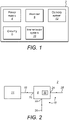
- embodiment aerosol generation apparatus 2 includes a power supply 4, for supply of electrical energy.
- the electrical energy may be supplied to an atomizer 6 and/or electrical circuitry 8.
- the power supply 4 may include an electric power supply in the form of a battery and/or an electrical connection to an external power source.
- the apparatus 2 may include a precursor transmission system 10 to transmit precursor to the atomizer 6 for formation of aerosol therefrom.
- a delivery system 12 delivers the aerosol to a user.
- embodiment aerosol generation apparatus 2 includes the precursor transmission system 10 having a storage portion 14 for storage of the precursor.
- the storage portion 14 may be arranged as a reservoir (not shown) or other suitable arrangement portion depending on the physical state of the precursor.
- the precursor transmission system 10 includes a transmission unit 16 to transmit the precursor from the storage portion 14 to the atomizer 6.
- the transmission unit 16 may include one or more of: an absorbent member (e.g. cotton) arranged for transmission by capillary action; a conduit; a valve; a pumping system, which may include an electrically operated pump.
- the precursor transmission system 10 may be omitted.
- the precursor may be arranged as a consumable pod (e.g. as a liquid or gel), wherein an atomizer includes a heated receptacle for the pod.
- the delivery system 12 includes a flow path 18 to transmit aerosol from the atomizer 6 to a user.
- the atomizer 6 includes a precursor inlet 20.
- the atomizer 6 includes a flow inlet 22 and an outlet 24 of the flow path 18 for passage of flow through the atomizer 6.
- the flow path 18 receives aerosol from the outlet 24 and does not pass through the atomizer 6.
- the flow path 18 includes an inlet 26, which may be arranged through a housing of the apparatus 2.
- the flow path 18 includes an outlet 28 for delivery of the aerosol and inlet flow to the user.
- the outlet 28 may be arranged as a mouthpiece or other suitable delivery member.
- the atomizer 6 includes a heating system 30, which may be arranged as one or more electrically resistive heating elements (not shown).
- a heating element may be arranged as a wire or filament.
- a heating element may be operatively connected to the precursor transmission unit 16 to heat precursor of the transmission unit 16.
- the one or more heating elements may be arranged within and/or in fluid communication with the flow path 18, e.g. to be cooled by said flow.
- a cartomizer integrates a storage portion 14 and transmission unit 16 of the transmission system 10 and heating system 30 in a common housing.
- the cartomizer including a predetermined amount of the precursor.
- the circuitry 8 regulates electrical energy from the power supply 4 to the heating system 30.
- Proximal a heating element the precursor may be converted to a supersaturated vapour, which subsequently condenses to form an inhalable aerosol.
- precursor is converted to aerosol, it is replaced by further precursor supplied by the transmission unit 16, e.g. by a pumping action, until the storage portion 14 is spent.
- the electrical energy supplied to the heating system 30 may be controlled with the circuitry 8 by one of the following or other like circuitry: pulse width modulation (PWM) via an electrically operated switch, or by other suitable means, e.g. by chopping of an alternating current waveform; a direct current (DC): DC converter, such as a Buck converter; a linear regulator.
- PWM pulse width modulation
- DC direct current
- DC converter such as a Buck converter
- linear regulator a linear regulator
- the circuitry 8 implements some form of control of the temperature of the heating system 30, e.g. by closed loop control.
- the control may comprise regulating one of the: electrical potential; current; power; temperature; other related quantity to remain at a target value through (or over) the heating system 30.
- the heating system 30 may include resistive elements arranged within the flow path 18, inhalation through the flow path has the effect of cooling the heating system 30.
- Said cooling influences the electrical resistance of the resistive elements, and therefore the degree of cooling can be representative of the intensity of the user inhalation, i.e. the flow rate through the flow path, and since the amount of precursor delivered as an aerosol from the transmission unit 16 may have a dependency on the intensity of the inhalation, the resistance can be used to determine the property of the flow as defined herein.
- the change in electrical current to maintain a constant voltage during an inhalation can be representative of the intensity of the inhalation.
- a temperature of the heating system is regulated at a target temperature, e.g. by proportional-integral-derivative (PID) or other like control algorithm
- PID proportional-integral-derivative
- the power (or other related quantity such as electrical current) to maintain the target temperature during an inhalation can therefore be representative of the intensity of the inhalation.
- a temperature of the heating system 30 may be determined by measuring the electrical resistance as described above and by implementation of an empirically determined relationship between electrical resistance and temperature.
- the circuitry may implement a dedicated temperature sensor arranged in operative proximity to the heating system 30.
- the circuitry 8 may comprise a trigger (not shown) to detect when aerosol formation is required.
- the circuity 8 may effect the supply of electrical energy to the heating system 30 upon the determination of triggering of the trigger.
- the trigger may detect when a user action suggests aerosol formation is required. Such a request may be implicit, such as via inhalation, or explicit, such as via a button press.
- the trigger may comprise an actuator being actuated by physical contact (e.g. a vaping button), including by a digit of a hand of the user. Examples include a button or a dial.
- the trigger may comprise an inhalation sensor operable to detect user inhalation through the flow path 18.
- the inhalation sensor may comprise a flow meter or a pressure sensor operable to determine flow pressure, including by capacitive sensing of a pressure respondent displaceable diaphragm.
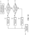
- an embodiment arrangement of the apparatus 2 comprises: a cartomizer 32 interconnecting a power supply 4 and a mouthpiece 34.
- the mentioned components may be connected in a modular fashion, including by bayonetted or threaded connection types or other suitable connection.
- the apparatus 2 is geometrically elongated along a longitudinal axis.
- the mentioned components can be arranged in the form of an elongated cylindrical shape, so as to replicate that of a cigar or cigarette.
- the mentioned components are alternatively arranged; e.g. the atomizer may be arranged separable from a storage portion.
- One or more of the mentioned components may be arranged in a common housing 35.
- an electrically operated aerosol generation system 36 for generation of an aerosol may implement features of any of the preceding embodiments or other embodiments disclosed herein.
- the system 36 is configured to generate an aerosol from an aerosol-forming precursor and comprises the heating system 30 to heat said precursor to generate the aerosol.
- the flow path 18 includes the inlet 26 for air inlet and the outlet 28 for delivery of the aerosol and inlet air.
- the heating system 30 is arranged in fluid communication with the flow path 18, including to receive flow 50 of the flow path.
- Electrical circuitry 8 at block 38 determines (e.g. measures) a property of electrical energy through the heating system 30.
- the dependency of the property with respect to time may be determined. Examples of suitable properties are as disclosed herein, which include current or voltage.
- suitable properties are as disclosed herein, which include current or voltage.
- the term "determining a property of electrical energy through the heating system" or "a property of electrical energy through the heating system” may refer to direct measurement of the property of the electrical energy through the heating system and/or a representative measurement of the property of the electrical energy elsewhere in the circuitry associated with the heating system (e.g. a resistor in parallel or series with the heating system, which may include a shunt resistor).
- the electrical circuitry 8 at block 40 determines a second order time derivative of the determined property of the electrical energy through the heating system 30.
- determination of a second order time derivative or “based on the second order time derivative” (or a like term) may include a representative quantity without explicit formulation, as well as with explicit formulation. Exemplary derivation methods for the second order derivative will be provided.
- Electrical circuitry 8 at block 42 determines a characteristic of the second order time derivative, examples of which are as disclosed herein, which include features such as a peak to peak value of maxima and minima.
- characteristic of the second order time derivative is to be understood as not limited to a single feature; e.g. it may comprise said peak to peak value and a time of a maximum; further examples will be provided.
- Electrical circuitry 8 at block 44 processes the determined characteristic of the second order time derivative to determine the property related to the flow.
- Examples of the property related to the flow are as disclosed herein, which include an amount of one or more components of the aerosol dispensed during a user inhale through the flow path 18.
- the property related to the flow may be determined based on a relationship between the property related to the flow and the characteristic of the second order time derivative; e.g. the relationship may be based on empirical data, examples of which will be provided.
- the circuitry 8 may implement alternative procedural steps, e.g. a fixed operation is performed on the characteristic.
- Electrical circuitry 8 at optional block 46 outputs the determined property related to the flow, which may include providing instructions to a user interface to display the determined property and/or to store said property, examples of which will be provided.
- circuitry 8 it will be understood that the process blocks 38-46 (or any other block associated therewith and like process steps of other embodiments disclosed herein) may be executed centrally on the apparatus 2 and/or distributed on other circuitry associated with the system 36, e.g. a peripheral device 48, which may be implemented as a smartphone.
- circuitry 8 for determination of the property of electrical energy through the heating system 30 may be implemented in various manners.
- the circuitry 8 implements a circuit for determining the property of the electrical energy through the heating system 30.
- the circuitry 8 includes a measurement unit 52 to measure a property of the electrical energy through or over a heating element of the heating system 30.
- the measurement unit 52 may be implemented as a resistor (e.g. a shunt resistor, not shown) arranged in series with the heating system 30 and a potentiometer (not shown) arranged to measure the electrical potential over the resistor.
- the electrical potential over the resistor may be converted to current by division of the resistance. Accordingly, the property of the electrical energy through the heating system 30 may be based on current and/or electrical potential.
- a processor 54 determines the property of the electrical energy based on a signal from the measurement system 52.
- the measurement unit may have other implementations, e.g. a potentiometer arranged to measure the electrical potential directly over the heating system or other property that may include phase or power.
- the processor may implement elements of the measurement unit, e.g. the potentiometer as an algorithm and/or a combinational logic circuit.
- the processor may also implement elements of a control system to control the electrical energy to the heating system, e.g. for PWM control, or DC:DC conversion.
- the processor 54 may implement determination of the second order time derivative of the variation of the property of the electrical energy through the heating system 30 and subsequent determination of a property related to the flow as will be discussed.
- the heating system 30 may comprise a single or multiple heating elements.
- the material of the heating element may be selected to have a high temperature coefficient of resistance ⁇ , e.g. 30-90 ⁇ 10 4 , such as Nickel.
- the or each heating element of the heating system 30 may be heated to a range to cause vaporisation of the precursor without combustion of the precursor, e.g. to 150-350 °C.
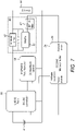
- the circuitry 8 includes exemplary componentry for illustrative purposes.
- the measurement system 52 is implemented as 2 m ⁇ shunt resistor 58, which is arranged in series with the heating system 30.
- the heating system 30 has a 200 m ⁇ electrically resistive load.
- An amplifier 60 amplifies the electrical potential over the shunt resistor 58.
- the amplifier is an INA215 by Texas Instruments with a gain of 50.
- Filter 62 is arranged to filter the amplifier 60 output, e.g. to remove noise including spurious modes.
- the processor 54 is implemented as a microcontroller 64.
- the microcontroller 64 is a CC2540 by Texas instruments.
- a DC-DC converter 56 (which in the embodiment is implemented as a buck converter) is arranged to provide a stabilised continuous voltage from the power supply 4.
- the DC-DC converter is a LM212 Buck by Texas Instruments.
- the power supply 4 has a nominal supply of 3.7 V.
- the DC-DC converter 56 outputs a continuous voltage of 2.5V, but may be controlled to 1.9-2.75V.
- the microcontroller 64 provides control of the DC-DC converter 56.
- a potentiometer 66 is arranged to provide a reference voltage to the microcontroller 64 and DC-DC converter 56.
- the potentiometer 66 is an MCP4013 by Microchip. The voltage is controlled by the microcontroller 64, which sets the reference voltage of the potentiometer 66.
- the electrical potential over the shut resistor 58 may be converted to current by division of said resistance. Accordingly, the property of the electrical energy through the heating system 30 may be based on current and/or electrical potential, or other quantities that may be derived therefrom, such as power.
- the second order time derivative of the determined property of the electrical energy through the heating system 30 is relatively independent of the specific implementation (e.g. resistances) of components of the circuitry 8. Moreover, said independence may reduce any effect of variations of electrical componentry (e.g. manufacturing tolerances) implementing the same circuitry 8, e.g. for batches of the same apparatus 2.
- the filter 62 may be implemented as a low pass filter, e.g. a resistor-capacitor (RC) filter.
- the pass frequency may be below 20 Hz.
- the filter (or an additional filter) is implemented as a digital filtering algorithm (or logic circuit) optionally arranged on the processor 54.
- a digital filter can advantageously be field configured by the processor 54.
- the filter may implement a smoothing algorithm to increase signal-to-noise ratio with minimal distortion; a suitable implementation includes a Savitzky-Golay filtering algorithm.
- the filter is selected to filter out oscillations due to bubbles in the reservoir or other fluctuations.
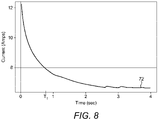
- line 72 represents the time dependency of electrical current through the heating system 30 when measured using the embodiment circuitry 8 shown in figures 6 or 7 .
- a similar time dependency may be obtained when measuring other properties of the electrical energy through the heating system; examples include power.
- a constant electrical potential is maintained over the heating system 30.
- the electrical current through the heating system 30 causes the or each heating element thereof to heat up.
- the temperature increase of the heating element causes a resistance increase, which due to regulation of a constant electrical potential has a resultant effect of decreasing the electrical current through the heating system 30.
- the electrical energy is applied to the heating system 30. It can be observed that the electrical current through the heating system 30 decreases in an exponential manner. This is due to the heating system 30 exhibiting a substantial initial temperature increase as it is heated, followed by convergence to a constant temperature. Since the electrical resistance is proportional to the temperature, to maintain the constant electrical potential, the current exhibits corresponding exponential decay.
- the circuitry 8 implements a constant current source, which is arranged to maintain a constant current over the heating system 30.
- a constant current source which is arranged to maintain a constant current over the heating system 30.
- the electrical potential over the constant current source increases, thus the electrical potential exhibits a similar time dependency as for the electrical current of the preceding embodiments.
- a similar time dependency may be obtained when measuring the power over the heating system or other representative quantity. It will thus be understood that the relationship between the property of electrical energy through the heating system 30 and the property related to the flow of the flow path may apply to various electrical quantities that are selected based on the implementation of the circuitry 8.
- heat is dissipated from the heating system 30 to the flow 50, e.g. by convective heat transfer of thermal energy from the heating element to the flow stream.
- the heat dissipation of the heating system 30 is thus related to the flow 50 through the flow path 18. Since the temperature of the heating element is related to its electrical resistance, the temperature thus influences the property of the electrical energy through the heating system 30 (e.g. the electrical potential over the heating system 30 or current through the heating system 30 depending on the implementation of the circuitry 8 ).
- the electrical energy through the heating system 30 is thus related to various properties of the flow 50 in the flow path 18 as will be discussed.
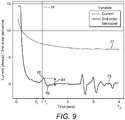
- line 72 shows the current during an inhalation and line 73 shows the current in absence of an inhalation.
- Line 78 is the second order time derivative of line 72.
- a user inhalation is initiated and terminated respectively. It can be seen that the initiation of the inhale causes an initial oscillation 75 in the current followed by a period of increased current 77 and an oscillation 79 at termination. The effect is more pronounced in the second order time derivative 78 of the current.
- the initial oscillation 75 ceases to have an effect on the second order time derivative 78.
- the termination oscillation 79 initiates an effect on the second order time derivative 78.
- the current decreases from an initial magnitude of over 12 amps to: 8.5-7.5 amps between 0.5 and 1 seconds; 7.5-7 amps between 1 and 2 seconds; a nominal value of 6.5-7 amps after about 2 seconds.
- current With the nominal value as a reference, current thus falls by over 70% in the first 0.5 seconds. It may be preferable to measure the effect of the user inhale on the current through the heating system 30 following 0.5 seconds, wherein the current has stabilised and the effect of the oscillations due to inhalation may appear more pronounced.
- the user inhale occurs following the supply of a predetermined amount of electrical energy and/or with some preheating of the heating element to enable the effect of the initiation of the user inhale to be captured.
- nominal value may refer to a normal operating value of a signal of the electrical energy, which the circuitry 8 may be designed to operate with.
- Nominal may refer to a value that the signal converges to or about.
- circuitry 8 implements an embodiment process for stabilising a property of the electrical energy through the heating system 30.
- the process may be implemented in combination with the embodiment process illustrated in figure 4 , or another embodiment disclosed herein.
- the circuitry 8 applies a predetermined amount of electrical energy to the heating system 30.
- the predetermined amount of electrical energy stabilises the property of electrical energy (e.g. the current in the exemplary embodiment) through the heating system 30.
- the circuitry 8 determines a property related to the flow 50 of the flow path 18 based on the property of the electrical energy through the heating system 30 subsequent to the applied predetermined amount of electrical energy, i.e. with said property stabilised, examples of which will be provided.
- Inhalation (which may include initiation of inhalation) following application of the predetermined amount of electrical energy may be ensured by implementing one or more embodiment modes of operation of the circuitry 8.
- the predetermined amount of electrical energy is applied upon determination of a trigger as previously described.
- the trigger may comprise an actuator actuated by physical contact (e.g. a vaping button), including by a digit of a hand of the user.
- the electrical circuitry 8 may implement the actuator with electrical energy applied to the atomizer 6 for the duration of the actuation. It has been found that with such an actuator most users initiate inhalation after 0.5 or 1 seconds of actuation. Thus, the circuitry 8 can be specifically configured to apply the predetermined amount of electrical energy before 0.5-1 second.
- Said configuration can be implemented by the control system of the processor 54 for regulation of electrical energy to the heating system 30 (e.g. the DC:DC converter or PWM based control system applies the predetermined amount of electrical energy in the first 0.5-1 second or other suitable time period T 1 ).
- the control system of the processor 54 for regulation of electrical energy to the heating system 30 (e.g. the DC:DC converter or PWM based control system applies the predetermined amount of electrical energy in the first 0.5-1 second or other suitable time period T 1 ).
- the circuitry 8 implements the trigger as a motion sensor or facial recognition sensor (e.g. a camera with image processing) to determine intent to initiate an inhalation.
- a motion sensor or facial recognition sensor e.g. a camera with image processing
- the circuitry 8 may implement enabling of inhalation through the flow path 18 only when the heating system 30 is heated to a predetermined temperature and/or the current is within a particular range of the nominal value (e.g. ⁇ 40 % or ⁇ 25 %).
- the circuitry 8 may enable inhalation by means of an electrically operated value or other flow regulation device.
- the circuitry 8 applies the predetermined amount of electrical energy over the first time period T 1 . Initiation of the inhale through the flow path 18 is indicated by line 74 at T i , which occurs after T 1 and during a subsequent time period. The circuitry 8 thus determines the property related to the flow through the flow path as will be discussed.
- the circuitry 8 may be configured to apply the predetermined amount of electrical energy over a T1 duration of 0.3-2, or 0.6-1.5 or less than 1 or 0.5 seconds.
- the property of the flow is based on an oscillation at termination of the inhalation (examples of which will be provided); thus, in some examples, the T i occurs before the predetermined amount of electrical energy has been fully applied.
- the predetermined amount of electrical energy may be 20, 25 or 30 Joules (each ⁇ 40 % or ⁇ 25 % or ⁇ 10 %).
- the predetermined amount of electrical energy can include 2.5V applied for T 1 (as defined by the previous ranges).
- the predetermined amount of electrical energy may be to preheat a heating element of the heating system 30 to a predetermined temperature range from which may be cooled during said inhale.
- the predetermined temperature range may be selected to cause vaporisation of the precursor without combustion of the precursor, e.g. to 150-350 °C or 200-250 °C.
- the temperature of the heating element may be determined by various implementations, which include: resistance of the heating system; a dedicated temperature sensor; empirical data (e.g. a particular amount of energy is known to effect an experimentally determined temperature range).
- the predetermined amount of electrical energy may be to stabilise the property of the electrical energy through the heating system 30 to ⁇ 25 % or ⁇ 40 % of the nominal value.
- the nominal value of the current may be taken as 6.5 amps, thus + 40 % or + 25 % equates to 9.1 amps and 8.1 amps respectively, 8.1 amps occurs during T 1 .
- the same ranges may be applied to other properties (e.g. electrical potential) of the electrical energy through the heating system 30 in other embedment implementations of the circuitry 8.
- the predetermined amount of electrical energy may be to stabilise the property of the electrical energy through the heating system so that oscillations caused by the user inhale through the flow path can be extracted and processed.
- the oscillations may include those in a first or second order time derivative as will be discussed.
- the specific amount of electrical energy to achieve the aforementioned stabilisation will depend on the implementation of the apparatus 2, which includes implementation of: the circuitry 8; heating system 30, including the resistance of the heating element; the flow path. Thus, it will be understood that the specific amount of electrical energy may be determined based on empirical data.
- the current 72 exhibits notable oscillation (which can be more clearly seen in the corresponding second order time derivative 74 ).
- the oscillation is electrical noise caused by overheating of the heating element of the heating system 30. It may therefore be desirable to configure the circuitry 8 such that the user inhale through the flow path 18 occurs prior to the electrical noise, such that the electrical noise may not interfere with measurement of the inhale. This may be achieved by application of the predetermined amount of electrical energy as close to initiation of the user inhale as possible.
- circuitry 8 that applies the predetermined amount of electrical energy in combination with processing of the second order time derivative to calculate the property of the flow, examples of which will be provided.
- the property of the electrical energy through the heating system 30 without numerical differentiation may be processed to calculate the property of the flow, examples of which will be provided.
- the circuitry 8 at block 40 determines a second order derivative with respect to time of the determined property of the electrical energy through the heating system 30.
- Determination of the second order time derivative may be implemented by an algorithm (or logic circuit), which may be arranged on the processor.
- the finite difference method e.g. Newton's difference quotient, symmetric difference or a higher-order method
- Derivation of the derivative may also be determined by electrical componentry, e.g. a finite difference method is implemented by a capacitor arranged to introduce a delay in the property of the electrical energy through the heating system 30 and a differential amplifier to determine a derivative from the property of the electrical energy and delayed property of the electrical energy.
- the characteristic feature of the second order time derivative may be extracted by the circuitry 8, including by an algorithm (or logic circuit) arranged on the processor.
- the specific characteristic to be extracted may depend on the particular relationship that is implemented to determine the property of the flow of the flow path 18, examples of which will be provided.
- the relationship may require extraction of a class comprising one or more features (referred to as input values), of the second order derivative, all of which are encompassed by the term "characteristic feature of the second order time derivative".
- processing may include the implementation of a particular relationship to determine the property of the flow 50 of the flow path 18.
- the relationship can be implemented by the circuitry 8, including by an algorithm (or logic circuit) arranged on the processor.
- the term "relationship” may refer to a relationship between the property of the electrical energy through the heating system 30 and the property of the flow of the flow path 18.
- the relationship may be an empirical relationship, e.g. one obtained by experimentally obtained data.
- the empirical data can be stored on a memory associated with the circuitry 8.
- an "empirical relationship” may also be referred to as a “stored relationship”, and the terms “empirical” and “stored” may be used interchangeably.
- the relationship may include a mathematical function, with one or more input variables and an output variable.
- the output variable comprises the property of the flow.
- the one or more input variables comprises the previously described class of one or more characteristics.
- a range of suitable output values is provided under the definition of the "property related to the flow”.
- a range of suitable input values i.e. a class
- the definition of the "characteristic of the second order time derivative" is provided under the definition of the "characteristic of the second order time derivative", and/or other features of the electrical energy through the heating system 30.
- Coefficients A - F are determined by regression of empirical data and have the respective values: 0.5965; 0.1223; 0.002088; 0.0004042; 0.05651;134.0.
- the input values comprise: a peak to peak magnitude 84, which is denoted as “ I "; the constant voltage maintained over the heating system 30, which is denoted as “V” in mV; the duration of the electrical energy applied to the heating system “ T d “ in mSec; the initiation time of the inhalation " T i “ in mSec. Since the voltage V is generally a constant, E and V may be replaced as a single coefficient.
- the input values include: a voltage V of 2.51 V; a duration of the electrical energy T d of 3.98 7 seconds; T i of 1.035 seconds; an intensity I of 1.370.
- the above relationship determines M as 12.9 mg with an experimental error of ⁇ 2-3 %.
- the experimentally obtained value of M was obtained by measuring the depletion of a storage portion containing the precursor. A user inhale through the flow path was replicated by a pump with a calibrated representative flow rate of 18.33 ml/s.
- the amount of individual components of the aerosol e.g. nicotine
- the circuitry 8 may implement various conditions to search and locate the correct maximum 80 and minimum 82. These are exemplified for the implementation of the circuitry 8 shown in figure 7 as: determine possible maxima and minima for 1.5 seconds following initiation of the electrical energy to the heating system; determine greatest difference between adjacent maxima 80 and minima 82; disregard if time difference between adjacent maxima 80 and minima 82 is greater than 1 second; disregard if the absolute of peak to peak 84 is not greater than 0.19; the absolute of peak to peak 84 must be greater than that of an absolute of the peak to peak of a later occurring adjacent maximum and minimum multiplied by 1.18; the absolute of peak to peak 84 must be greater than that of an absolute of the peak to peak of an earlier occurring adjacent maximum and minimum multiplied by 1.13.
- the circuitry 8 may determine the time duration T d of the electrical energy being applied to the heating system 30 by the previously described duration of actuation of the trigger (e.g. the vaping button or other suitable trigger).
- the circuitry 8 may determine the initiation of inhalation T i by the time of the maxima 80.
- a representative time duration of inhalation (which is not used in equation 1) may be determined by T d - T i .
- the peak to peak 84 may exhibit a similar magnitude in both instances. It may therefore be advantageous to utilise the second order derivative (as opposed to the first order derivative, or current without numerical differentiation) for determination of input values. Any dependency of the peak to peak magnitude 84 and the initiation time T i (due to exponential decay of the current) may be accounted for based on the dependence of Equation (1) on the initiation time T i . Moreover, it is apparent that the second order derivative converges faster to a nominal value than current without numerical differentiation.
- Equation (1) if the inhalation is initiated sufficiently early, a saddle point in the current 72 may occur at line 74; consequently, the relationship may be adapted to search for a saddle point and to utilise the initiation of the point of zero gradient in the saddle (instead of the maxima at 80 ) to derive the peak to peak 84.
- Coefficients X - Z are determined by regression of empirical data and have the respective values: -0.00003115; 0.1227; 295.2.
- the input values comprise: the constant voltage maintained over the heating system 30, denoted as " V " (in mV); the duration of the electrical energy applied to the heating system "T d " (in mSec).
- the input values include: a voltage V of 2.51 V; a duration of the electrical energy T d of 3.987 seconds.
- the above relationship determines M as 12.7 mg with an experimental error of ⁇ 4 - 6 %.
- the experimentally obtained value of M was obtained by measuring the depletion of a storage portion containing the precursor. A user inhale through the flow path was replicated by a pump with a calibrated representative flow rate of 18.33 ml/s.
- the duration of the electrical energy T d through the heating system 30 can be determined as discussed for Example 1.
- Equation (2) may be implemented to determine the property of the flow.
- Example 1 and Example 2 provide example relationships between the electrical energy through the heating system 30 and the property of the flow of the flow path 18. Other relationships may be implemented.
- a variant of Example 1 may include, as input values, one or more of: the period between the maximum 80 and minimum 82, or other period related thereto; the area under the maximum 80 and/or minimum 82; a magnitude of the maximum or minimum 82 (as opposed to the peak to peak value 84 ); alternative maxima and or minima may be used, including those associated with the end of the inhale. Alternatively, a gradient/period of the period between the oscillations caused by initiation and termination of inhalation may be utilised.
- the input values may be obtained from a first derivative of the property of the electrical energy through the heating system 30, or of the property of the electrical energy through the heating system 30 (i.e. without numerical differentiation).
- a feature of an oscillation in a property of the electrical energy through the heating system may be used as an input value, including as the only input value; e.g. Equation (1) is adapted to have, as the only input value, the peak to peak 84, which may be based on empirical data, which thus replaces the time dependency in the equation.
- the duration of the user inhale may be obtained from the second order time derivative and may be used as an input value instead of the initiation time of the inhalation and/or duration of the electrical energy applied to the heating system.
- a variant of Example 2 may include, as an input value, the duration of the user inhale, which may be determined from the second derivative of the property of the electrical energy through the heating system 30, or the property of the electrical energy through the heating system 30 (i.e. without numerical differentiation).
- equations (1) or (2) may be alternatively formulated to determine: volume of aerosol; mass or volume of flow (i.e. the summation of the aerosol and air); velocity of the flow.
- the determined property of the flow may be utilised in various manners, depending on what it is. It may be utilised as one or more of the following: display to a user on a user interface (e.g. on a peripheral device, such as a smartphone 48, or on the apparatus 2 ); stored on a memory associated with the system 36; used as a basis for control of the apparatus 2 (e.g. it is determined that the depletion of precursor is greater than a threshold and aerosol generation is reduced or otherwise controlled).
- a user interface e.g. on a peripheral device, such as a smartphone 48, or on the apparatus 2
- stored on a memory associated with the system 36 used as a basis for control of the apparatus 2 (e.g. it is determined that the depletion of precursor is greater than a threshold and aerosol generation is reduced or otherwise controlled).
- the circuitry 8 generates instructions for the user interface 94 to display information based on the determined property of the flow.
- the instructions may be for processing, by a display driver, for driving the user interface 94.
- the property of the flow is an amount of one or more components of the aerosol present in an inhale
- the quantity of said amount(s), and/or the amount from an aggregate of a plurality of inhales may be displayed.
- the described embodiments include circuitry 8 at block 100, to determine a property of electrical energy through the heating system 30; at block 102, the circuitry 8, to determine an oscillation due to initiation and/or termination of a user inhale through the flow path 18.
- the process may be implemented in combination with the embodiment process illustrated in figures 4 , and/or 12, or another embodiment disclosed herein.
- oscillation may refer to one or more of: maxima; minima; saddle point.
- the maxima and minima may be adjacent.
- the oscillation may be caused by an inhalation through the flow path 18 (rather than by electrical noise or other interference).
- oscillation may refer to a certain feature or pattern of a parameter, such as (but not limited to) a feature or pattern of a property of electrical energy through the heating system. Referring to figures 9 to 11 , such a property may be, e.g., a current over time, and/or a first/second order derivative thereof.
- an "oscillation" may occur at a portion of a function of a property, such as the functions illustrated by the graphs in Figures 9 to 11 .
- a function of a property such as the functions illustrated by the graphs in Figures 9 to 11 .
- the portions of graphs 72 and/or 78 between line 74 and the vertical line (not shown) through point 82, or relatively close thereto may be referred to as an "oscillation”.
- an "oscillation" may be seen in the portions of graphs 72 and/or 78 between lines 74 and 81 or between 83 and 76.
- an "area of an oscillation” may refer to an area at least a section of whose boundary is formed by at least a section of the graph over time representing the oscillation.
- the area of the oscillation represented by the portion of graph 78 between lines 80 and 82 may thus refer to an area which is on one side bounded by the entire or part(s) of the portion of graph 78 between lines 80 and 82.
- Other sides of the area may be bounded by horizontal lines, such as the axis in the coordinate system which is denoted by "t" (the time axis) and/or by vertical lines, such as dashed lines 74 and 81 (or their extensions); or any other lines that are suited to define boundaries of an area.
- a "maximum” (of or comprised by an oscillation) may refer to a local maximum.
- a “minimum” (of or comprised by an oscillation) may refer to a local minimum.
- the local maximum 80 and/or 108 of the oscillation as described above may be referred to as a "maximum”.
- the local minimum 82 and/or 110 of the oscillation as described above may be referred to as a "minimum”.
- an oscillation is bounded by a minimum and/or a maximum.
- an "amplitude” may refer to the absolute difference of a property of electrical energy through the heating system between different points of time.
- an “amplitude” may thus refer to the difference between a “maximum” and/or a “minimum” (peak to peak amplitude) as described above, such as illustrated by references 84 or 112.
- an “amplitude” may refer to the distance of a maximum or a minimum from the time axis (peak amplitude).
- a "period of an oscillation” may refer to a duration of an "oscillation” as described above.
- a “period” may start and end at the endpoints of a respective “oscillation”.
- the startpoint and endpoint of the oscillation may be freely chosen.
- the circuitry 8 is configured to process one or more features of the oscillation to determine a property related to flow.
- the processing may include the one or more features used as the input values for the described relationship between the property of the electrical energy through the heating system 30 and the property of the flow of the flow path 18, with the property of the flow being the output value.
- the circuitry 8 is configured to optionally output the property related to flow (as discussed previously).
- the property related to the flow of block 104 may include an amount of one or more components of aerosol dispensed in the inhale through the flow path 18.
- an input value can be determined from the oscillation due to initiation of a user inhale through the flow path 18.
- the oscillation may be based on the second order time derivative 78, and includes a maximum 80 and an adjacent minimum 82.
- the peak to peak amplitude 84 can be extracted from the maximum 80 and minimum 82 and used as the input value.
- an input value can be determined from the oscillation due to termination of a user inhale through the flow path 18.
- the oscillation may be based on the second order time derivative 78, and includes a maximum 108 and an adjacent minimum 110.
- the peak to peak amplitude 112 can be extracted from the maxima 108 and minima 110 and used as the input value.
- the oscillation from either or both the initiation and termination of the inhale are related to an amount of one or more components of aerosol dispensed in the inhale through the flow path 18.
- input values may be determined from the oscillation due to termination and initiation.
- input values from one of the oscillation due to initiation or termination of the inhale may be used if the other is not available.
- the current 72 exhibits notable oscillation (which can be more clearly seen in the corresponding second order time derivative 74 ).
- the oscillation is electrical noise caused by overheating of the heating element of the heating system 30.
- the electrical noise may interfere with determination of the oscillation associated with the initiation and/or termination of inhalation. It may therefore be desirable to configure the circuitry 8 such that the user inhale through the flow path 18 occurs prior to the electrical noise, such that the electrical noise may not interfere with measurement of the inhale.
- the oscillation due to termination of inhale is interfered with by the electrical noise. It may therefore be difficult to accurately determine the oscillation due to termination of inhalation. Accordingly, it may be desirable to implement relationships (e.g. those discussed under Example 1) between the electrical energy through the heating system 30 and the property of the flow of the flow path 18 which do not require determination of the oscillation at termination of inhalation and require determination of oscillation at the initiation, since this oscillation is less likely to be subject to interference.
- the first derivative of the property of the electrical energy through the heating system 30 or the property of the electrical energy through the heating system 30 may be utilised.
- the second order derivative provides a more pronounced oscillation and may yield more accurate output values.
- the circuitry 8 may determine the oscillation due to inhalation and/or termination of the inhalation by comparison to one or more predetermined conditions, which are exemplified under Example 1 in relation to conditions to search and locate the maxima and minima.
- the input value e.g. the period between the maxima and minima, or other periods related thereto; the area under the maxima and/or minima; a magnitude of the maxima or minima (as opposed to the peak to peak value).
- the magnitude of the amplitude 84 is directly related to an amount of the one or more components M of aerosol dispensed, i.e. via the empirical relationship of Equation 1; the greater the magnitude of the amplitude the greater the amount of the component dispensed, e.g. via direct proportionality or other mathematical function relationship.
- the described embodiments may be implemented with the electrical circuitry 8 to determine a property related to the flow of the flow path 18 based on one of a plurality of different relationships between the electrical energy through the heating system and said property.
- the circuitry may implement a process comprising: measuring a property of the electrical energy through the heating system (e.g. the current as described previously or another property such as power or voltage); determining one or more characteristics from said measured property of the electrical energy (e.g. the input values for the previously described Example 1 or Example 2 or the herein described related variants or other like characteristics); selecting, based on the determined characteristics, one from a plurality of different empirical relationships between the measured property of the electrical energy and a property of the flow as defined herein (e.g. selecting Example 1 or Example 2 or another of the herein described related variants); implementing said relationship to determine the property of the flow as defined herein.
- a property of the electrical energy through the heating system e.g. the current as described previously or another property such as power or voltage
- determining one or more characteristics from said measured property of the electrical energy e.g. the input values for the previously described Example 1 or Example 2 or the herein described related variants or other like characteristics
- selecting, based on the determined characteristics one from a plurality
- the circuitry 8 may implement the relationship (e.g. Example 1 or Example 2 or other variant) according to an order of preference or a set of input values, which may be referred to as a "class".
- an embodiment process for implementing the plurality of relationships includes, at block 114, the circuitry 8 measuring the property of the electrical energy through the heating system 30 (examples of which were previously discussed).
- the circuitry 8 determines whether a first class of one or more input values can be determined from the determined property of the electrical energy through the heating system 30. If the first class can be determined, then block 118 is executed to output the property of the flow at block 120 . Block 118 implements a first relationship.
- the first class would be: the peak to peak magnitude 84, which is denoted as "I”; the constant voltage maintained over the heating system 30, which is denoted as “ V "; the duration of the electrical energy applied to the heating system "T d " ; the initiation time of the inhalation " T i ".
- the output value is the mass M of aerosol present in a user inhale through the flow path 18.
- condition 122 is executed.
- the circuitry 8 determines whether a second class of one or more input values can be determined from the determined property of the electrical energy through the heating system 30. If the second class can be determined, then block 124 is executed to output the property of the flow at block 120. Block 124 implements a second relationship.
- the second class would be: the duration of the electrical energy applied to the heating system " T d ".
- the second class can be determined, then at block 124 Equation (2) is implemented.
- the output value is the mass M of aerosol present in a user inhale through the flow path 18.
- a greater number than two relationships are implemented.
- the classes associated with a plurality of relationships may be determined, with the particular relationship implemented according to an order of preference.
- block 126 is executed.
- the circuitry 8 may determine the output value based on an output value determined from one or more prior user inhales through the flow path 18 (e.g. the output value from the previous inhalation is utilised as the output value or an average or other suitable representation based on output values from a plurality of prior inhalations is utilised as the output value).
- the information relating to prior output values may be stored on a memory communicatively coupled to a processor of the circuitry 8.
- the input values of the second class associated with the second relationship is a subset of the input values of the first class associated with the first relationship.
- Electrical circuitry 8 implemented in this manner allows the second relationship to be conveniently implemented using one or more of the input values of the first class in the event that all of those from the first class cannot be determined. Such an implementation may have reduced processing overhead.
- any machine executable instructions, or compute readable media may carry out a disclosed method, and may therefore be used synonymously with the term method, or each other.
Claims (16)
- - Système de génération d'aérosol (36) pour la génération d'un aérosol à partir d'un précurseur de formation d'aérosol, le système comprenant :- un système de chauffage à commande électrique (30) pour chauffer ledit précurseur afin de générer l'aérosol ;- un chemin d'écoulement (18) pour la transmission de l'écoulement, y compris l'aérosol, à un utilisateur ; le système de chauffage étant agencé en communication fluidique avec le chemin d'écoulement ; et- un circuit électrique (8) conçu pourdans lequel le circuit électrique est conçu pour appliquer la quantité prédéterminée d'énergie électrique au cours d'une première période, qui est comprise entre 0,3 et 2 secondes, de préférence entre 0,6 et 1,5 seconde.- appliquer une quantité prédéterminée d'énergie électrique au système de chauffage pour stabiliser une propriété de l'énergie électrique à travers le système de chauffage,
et- déterminer une propriété liée à l'écoulement du chemin d'écoulement sur la base de la propriété stabilisée de l'énergie électrique à travers le système de chauffage ; - Système selon l'une quelconque des revendications précédentes, dans lequel la quantité prédéterminée d'énergie électrique est d'au moins 10 joules, de préférence d'au moins 20 joules, de manière plus préférable d'au moins 30 joules, et de manière encore plus préférable d'au moins 50 joules.
- Système selon l'une quelconque des revendications précédentes, dans lequel le circuit électrique (8) est conçu pour déterminer l'actionnement par l'utilisateur d'un déclencheur et, en réponse, pour appliquer ladite quantité prédéterminée d'énergie électrique à travers le système de chauffage (30).
- Système selon l'une quelconque des revendications précédentes, le système étant conçu de sorte que la quantité prédéterminée d'énergie électrique préchauffe un élément chauffant du système de chauffage (30) dans une plage de température prédéterminée comprise entre 150 et 350 °C, de préférence entre 200 et 250 °C.
- Système selon l'une quelconque des revendications précédentes, dans lequel la propriété de l'énergie électrique à travers le chauffage stabilisé par la quantité prédéterminée d'énergie électrique est le courant électrique.
- Système selon l'une quelconque des revendications précédentes, le système étant conçu de sorte que la quantité prédéterminée d'énergie électrique stabilise la propriété de l'énergie électrique à travers le système de chauffage (30) à + 25 % ou + 40 % d'une valeur nominale.
- Système selon l'une quelconque des revendications précédentes, dans lequel le circuit électrique (8) est conçu pour maintenir constante une propriété de l'énergie électrique à travers le système de chauffage, dans lequel ladite propriété constante est différente de la propriété de l'énergie électrique à travers le système de chauffage pour déterminer la propriété liée à l'écoulement du chemin d'écoulement.
- Système selon l'une quelconque des revendications précédentes, dans lequel le circuit électrique (8) est conçu pour déterminer la propriété de l'écoulement pendant une inhalation par l'utilisateur à travers le chemin d'écoulement.
- Système selon l'une quelconque des revendications précédentes, dans lequel le circuit électrique (8) est conçu pour déterminer la propriété liée à l'écoulement sur la base d'une relation stockée entre la propriété liée à l'écoulement et une caractéristique associée à une dérivée temporelle de second ordre de la propriété de l'énergie électrique à travers le système de chauffage (30).
- Système selon l'une quelconque des revendications précédentes, dans lequel la propriété liée à l'écoulement est une ou plusieurs des propriétés suivantes : une quantité d'un ou de plusieurs composants de l'aérosol ; un début d'inhalation ; une fin d'inhalation ; une durée d'inhalation.
- Procédé de détermination d'une propriété d'un écoulement d'un système de génération d'aérosol (36) pour la génération d'un aérosol à partir d'un précurseur de formation d'aérosol, le système de génération d'aérosol (36) comprenant un circuit électrique (8), un système de chauffage à commande électrique (30) pour chauffer ledit précurseur afin de générer l'aérosol, et un chemin d'écoulement (18) pour la transmission de l'écoulement, y compris l'aérosol, à un utilisateur, dans lequel le système de chauffage (30) est agencé en communication fluidique avec le chemin d'écoulement (18), le procédé étant mis en oeuvre par le circuit électrique (8) et comprenant :- la détermination d'une propriété liée à l'écoulement sur la base d'une propriété stabilisée de l'énergie électrique à travers le système de chauffage, la propriété stabilisée de l'énergie électrique ayant été obtenue en appliquant une quantité prédéterminée d'énergie électrique à un système de chauffage (30) ;
dans lequel la quantité prédéterminée d'énergie électrique est appliquée au cours d'une première période, qui est comprise entre 0,3 et 2 secondes, de préférence entre 0,6 et 1,5 seconde. - Procédé selon la revendication 11, comprenant en outre la génération d'instructions pour une interface utilisateur pour afficher des informations basées sur la propriété déterminée de l'écoulement et l'affichage de ces informations.
- Programme informatique comprenant des instructions qui, lorsqu'elles sont exécutées sur un circuit électrique programmable (6), exécutent le procédé selon la revendication 11 ou 12.
- Circuit électrique (8) pour déterminer une propriété d'un écoulement d'un système de génération d'aérosol à commande électrique (36) pour la génération d'un aérosol à partir d'un précurseur de formation d'aérosol, le système de génération d'aérosol (36) comprenant en outre un système de chauffage à commande électrique (30) pour chauffer ledit précurseur afin de générer l'aérosol, et un chemin d'écoulement (18) pour la transmission de l'écoulement, y compris l'aérosol, à un utilisateur, dans lequel le système de chauffage (30) est agencé en communication fluidique avec le chemin d'écoulement (18), le circuit électrique (8) étant conçu- pour déterminer une propriété liée à l'écoulement sur la base d'une propriété stabilisée de l'énergie électrique à travers le système de chauffage, la propriété stabilisée de l'énergie électrique ayant été obtenue en appliquant une quantité prédéterminée d'énergie électrique à un système de chauffage (30) ;
dans lequel le circuit électrique est conçu pour appliquer la quantité prédéterminée d'énergie électrique au cours d'une première période, qui est comprise entre 0,3 et 2 secondes, de préférence entre 0,6 et 1,5 seconde. - Circuit électrique (8) selon la revendication 14, conçu en outre pour générer des instructions pour une interface utilisateur afin d'afficher des informations basées sur la propriété déterminée de l'écoulement.
- Support lisible par ordinateur non transitoire comprenant le programme informatique selon la revendication 13.
Applications Claiming Priority (2)
| Application Number | Priority Date | Filing Date | Title |
|---|---|---|---|
| EP16207589 | 2016-12-30 | ||
| PCT/EP2018/050065 WO2018122408A1 (fr) | 2016-12-30 | 2018-01-02 | Système de génération d'aérosol à commande électrique |
Publications (2)
| Publication Number | Publication Date |
|---|---|
| EP3562341A1 EP3562341A1 (fr) | 2019-11-06 |
| EP3562341B1 true EP3562341B1 (fr) | 2022-10-19 |
Family
ID=57681491
Family Applications (1)
| Application Number | Title | Priority Date | Filing Date |
|---|---|---|---|
| EP18700310.8A Active EP3562341B1 (fr) | 2016-12-30 | 2018-01-02 | Système de production d'aérosol à commande électrique |
Country Status (6)
| Country | Link |
|---|---|
| US (1) | US11707094B2 (fr) |
| EP (1) | EP3562341B1 (fr) |
| JP (1) | JP2020503894A (fr) |
| CN (1) | CN110139573A (fr) |
| EA (1) | EA201991613A1 (fr) |
| WO (1) | WO2018122408A1 (fr) |
Families Citing this family (4)
| Publication number | Priority date | Publication date | Assignee | Title |
|---|---|---|---|---|
| JP2020503894A (ja) | 2016-12-30 | 2020-02-06 | ジェイ・ティ・インターナショナル・ソシエテ・アノニムJt International S.A. | 電気式エアロゾル発生システム |
| GB201703284D0 (en) * | 2017-03-01 | 2017-04-12 | Nicoventures Holdings Ltd | Vapour provision device with liquid capture |
| WO2020092245A1 (fr) * | 2018-10-29 | 2020-05-07 | Zorday IP, LLC | Cigarette électronique compatible avec un réseau |
| US11910826B2 (en) | 2021-01-18 | 2024-02-27 | Altria Client Services Llc | Heat-not-burn (HNB) aerosol-generating devices and capsules |
Family Cites Families (35)
| Publication number | Priority date | Publication date | Assignee | Title |
|---|---|---|---|---|
| US4899766A (en) | 1988-11-18 | 1990-02-13 | Ross Jr John R | Secondary smoke catcher |
| US5269327A (en) | 1989-12-01 | 1993-12-14 | Philip Morris Incorporated | Electrical smoking article |
| US5396907A (en) | 1993-07-20 | 1995-03-14 | Rojas Henao; Jerry | Device for containing secondary smoke |
| US6080973A (en) * | 1999-04-19 | 2000-06-27 | Sherwood-Templeton Coal Company, Inc. | Electric water heater |
| US6772756B2 (en) | 2002-02-09 | 2004-08-10 | Advanced Inhalation Revolutions Inc. | Method and system for vaporization of a substance |
| US7540286B2 (en) | 2004-06-03 | 2009-06-02 | Alexza Pharmaceuticals, Inc. | Multiple dose condensation aerosol devices and methods of forming condensation aerosols |
| US7167776B2 (en) * | 2004-09-02 | 2007-01-23 | Philip Morris Usa Inc. | Method and system for controlling a vapor generator |
| EP2100525A1 (fr) | 2008-03-14 | 2009-09-16 | Philip Morris Products S.A. | Système de génération d'aérosol à chauffage électrique et procédé |
| EP2110033A1 (fr) | 2008-03-25 | 2009-10-21 | Philip Morris Products S.A. | Procédé pour le contrôle de la formation de constituants de fumée dans un système électrique de génération d'aérosol |
| US8550068B2 (en) | 2010-05-15 | 2013-10-08 | Nathan Andrew Terry | Atomizer-vaporizer for a personal vaporizing inhaler |
| EP2468116A1 (fr) | 2010-12-24 | 2012-06-27 | Philip Morris Products S.A. | Système de génération d'aérosol disposant de supports pour gérer la consommation d'un substrat liquide |
| KR102029510B1 (ko) | 2011-10-27 | 2019-10-07 | 필립모리스 프로덕츠 에스.에이. | 향상된 에어로졸 생산을 가진 에어로졸 발생시스템 |
| EP2609820A1 (fr) * | 2011-12-30 | 2013-07-03 | Philip Morris Products S.A. | Détection d'un substrat formant un aérosol dans un dispositif de génération d'aérosol |
| PL2797448T5 (pl) | 2011-12-30 | 2019-12-31 | Philip Morris Products S.A. | Urządzenie do wytwarzania aerozolu z wykrywaniem przepływu powietrza |
| AU2012360820B2 (en) * | 2011-12-30 | 2017-07-13 | Philip Morris Products S.A. | Aerosol generating system with consumption monitoring and feedback |
| US9675114B2 (en) | 2012-11-08 | 2017-06-13 | Ludovicus Josephine Felicien Timmermans | Real time variable voltage programmable electronic cigarette and method |
| US9277770B2 (en) | 2013-03-14 | 2016-03-08 | R. J. Reynolds Tobacco Company | Atomizer for an aerosol delivery device formed from a continuously extending wire and related input, cartridge, and method |
| US9423152B2 (en) * | 2013-03-15 | 2016-08-23 | R. J. Reynolds Tobacco Company | Heating control arrangement for an electronic smoking article and associated system and method |
| US9491974B2 (en) | 2013-03-15 | 2016-11-15 | Rai Strategic Holdings, Inc. | Heating elements formed from a sheet of a material and inputs and methods for the production of atomizers |
| US9220302B2 (en) | 2013-03-15 | 2015-12-29 | R.J. Reynolds Tobacco Company | Cartridge for an aerosol delivery device and method for assembling a cartridge for a smoking article |
| US9884157B2 (en) * | 2013-03-15 | 2018-02-06 | Microdose Therapeutx, Inc. | Inhalation device, control method and computer program |
| US10251423B2 (en) | 2013-09-13 | 2019-04-09 | Nicodart, Inc. | Programmable electronic vaporizing apparatus and smoking cessation system |
| US9402422B2 (en) | 2013-11-01 | 2016-08-02 | Yuval Shenkal | Hybrid e-cigarette/vaporizer with exhale filter capability |
| US9635886B2 (en) * | 2013-12-20 | 2017-05-02 | POSiFA MICROSYSTEMS, INC. | Electronic cigarette with thermal flow sensor based controller |
| FR3017954B1 (fr) | 2014-02-21 | 2016-12-02 | Smokio | Cigarette electronique |
| US9924741B2 (en) | 2014-05-05 | 2018-03-27 | Rai Strategic Holdings, Inc. | Method of preparing an aerosol delivery device |
| CN104122179B (zh) * | 2014-08-05 | 2017-03-22 | 云南中烟工业有限责任公司 | 一种评价电子烟烟雾量的方法 |
| US9609895B2 (en) | 2014-08-21 | 2017-04-04 | Rai Strategic Holdings, Inc. | System and related methods, apparatuses, and computer program products for testing components of an aerosol delivery device |
| GB2529629B (en) * | 2014-08-26 | 2021-05-12 | Nicoventures Trading Ltd | Electronic aerosol provision system |
| US10179215B2 (en) | 2015-03-19 | 2019-01-15 | Altria Client Services Llc | Vaporizer for vaporizing a constituent of a plant material |
| GB2537121A (en) | 2015-04-07 | 2016-10-12 | Cigtronica Ltd | Inhalation device |
| US10244791B2 (en) * | 2015-05-15 | 2019-04-02 | Lunatech, Llc | Vaporizer with logic need based messaging platform |
| US20170135412A1 (en) * | 2015-11-17 | 2017-05-18 | Lunatech, Llc | Advanced microprocessor for electronic vapor device |
| US11147315B2 (en) * | 2016-07-25 | 2021-10-19 | Fontem Holdings 1 B.V. | Controlling an operation of an electronic cigarette |
| JP2020503894A (ja) | 2016-12-30 | 2020-02-06 | ジェイ・ティ・インターナショナル・ソシエテ・アノニムJt International S.A. | 電気式エアロゾル発生システム |
-
2018
- 2018-01-02 JP JP2019556737A patent/JP2020503894A/ja active Pending
- 2018-01-02 EP EP18700310.8A patent/EP3562341B1/fr active Active
- 2018-01-02 EA EA201991613A patent/EA201991613A1/ru unknown
- 2018-01-02 WO PCT/EP2018/050065 patent/WO2018122408A1/fr unknown
- 2018-01-02 CN CN201880005702.5A patent/CN110139573A/zh active Pending
- 2018-01-02 US US16/470,875 patent/US11707094B2/en active Active
Also Published As
| Publication number | Publication date |
|---|---|
| JP2020503894A (ja) | 2020-02-06 |
| WO2018122408A1 (fr) | 2018-07-05 |
| US11707094B2 (en) | 2023-07-25 |
| EP3562341A1 (fr) | 2019-11-06 |
| CN110139573A (zh) | 2019-08-16 |
| EA201991613A1 (ru) | 2019-11-29 |
| US20200085099A1 (en) | 2020-03-19 |
Similar Documents
| Publication | Publication Date | Title |
|---|---|---|
| US11484673B2 (en) | Electrically operated aerosol generation system | |
| EP3731679B9 (fr) | Système de production d'aérosol à commande électrique | |
| EP3562341B1 (fr) | Système de production d'aérosol à commande électrique | |
| EP3562537B1 (fr) | Système de génération d'aérosol à commande électrique | |
| US20190364971A1 (en) | Electrically Operated Aerosol Generation System | |
| EA043286B1 (ru) | Электрически управляемая система генерации аэрозоля | |
| EA044442B1 (ru) | Электрически управляемая система генерации аэрозоля |
Legal Events
| Date | Code | Title | Description |
|---|---|---|---|
| STAA | Information on the status of an ep patent application or granted ep patent |
Free format text: STATUS: UNKNOWN |
|
| STAA | Information on the status of an ep patent application or granted ep patent |
Free format text: STATUS: THE INTERNATIONAL PUBLICATION HAS BEEN MADE |
|
| PUAI | Public reference made under article 153(3) epc to a published international application that has entered the european phase |
Free format text: ORIGINAL CODE: 0009012 |
|
| STAA | Information on the status of an ep patent application or granted ep patent |
Free format text: STATUS: REQUEST FOR EXAMINATION WAS MADE |
|
| 17P | Request for examination filed |
Effective date: 20190729 |
|
| AK | Designated contracting states |
Kind code of ref document: A1 Designated state(s): AL AT BE BG CH CY CZ DE DK EE ES FI FR GB GR HR HU IE IS IT LI LT LU LV MC MK MT NL NO PL PT RO RS SE SI SK SM TR |
|
| AX | Request for extension of the european patent |
Extension state: BA ME |
|
| DAV | Request for validation of the european patent (deleted) | ||
| DAX | Request for extension of the european patent (deleted) | ||
| GRAP | Despatch of communication of intention to grant a patent |
Free format text: ORIGINAL CODE: EPIDOSNIGR1 |
|
| STAA | Information on the status of an ep patent application or granted ep patent |
Free format text: STATUS: GRANT OF PATENT IS INTENDED |
|
| INTG | Intention to grant announced |
Effective date: 20220610 |
|
| GRAS | Grant fee paid |
Free format text: ORIGINAL CODE: EPIDOSNIGR3 |
|
| GRAA | (expected) grant |
Free format text: ORIGINAL CODE: 0009210 |
|
| STAA | Information on the status of an ep patent application or granted ep patent |
Free format text: STATUS: THE PATENT HAS BEEN GRANTED |
|
| AK | Designated contracting states |
Kind code of ref document: B1 Designated state(s): AL AT BE BG CH CY CZ DE DK EE ES FI FR GB GR HR HU IE IS IT LI LT LU LV MC MK MT NL NO PL PT RO RS SE SI SK SM TR |
|
| REG | Reference to a national code |
Ref country code: GB Ref legal event code: FG4D |
|
| REG | Reference to a national code |
Ref country code: CH Ref legal event code: EP |
|
| REG | Reference to a national code |
Ref country code: IE Ref legal event code: FG4D |
|
| REG | Reference to a national code |
Ref country code: DE Ref legal event code: R096 Ref document number: 602018041928 Country of ref document: DE |
|
| REG | Reference to a national code |
Ref country code: AT Ref legal event code: REF Ref document number: 1525005 Country of ref document: AT Kind code of ref document: T Effective date: 20221115 |
|
| REG | Reference to a national code |
Ref country code: LT Ref legal event code: MG9D |
|
| REG | Reference to a national code |
Ref country code: NL Ref legal event code: MP Effective date: 20221019 |
|
| REG | Reference to a national code |
Ref country code: AT Ref legal event code: MK05 Ref document number: 1525005 Country of ref document: AT Kind code of ref document: T Effective date: 20221019 |
|
| PG25 | Lapsed in a contracting state [announced via postgrant information from national office to epo] |
Ref country code: NL Free format text: LAPSE BECAUSE OF FAILURE TO SUBMIT A TRANSLATION OF THE DESCRIPTION OR TO PAY THE FEE WITHIN THE PRESCRIBED TIME-LIMIT Effective date: 20221019 |
|
| PG25 | Lapsed in a contracting state [announced via postgrant information from national office to epo] |
Ref country code: SE Free format text: LAPSE BECAUSE OF FAILURE TO SUBMIT A TRANSLATION OF THE DESCRIPTION OR TO PAY THE FEE WITHIN THE PRESCRIBED TIME-LIMIT Effective date: 20221019 Ref country code: PT Free format text: LAPSE BECAUSE OF FAILURE TO SUBMIT A TRANSLATION OF THE DESCRIPTION OR TO PAY THE FEE WITHIN THE PRESCRIBED TIME-LIMIT Effective date: 20230220 Ref country code: NO Free format text: LAPSE BECAUSE OF FAILURE TO SUBMIT A TRANSLATION OF THE DESCRIPTION OR TO PAY THE FEE WITHIN THE PRESCRIBED TIME-LIMIT Effective date: 20230119 Ref country code: LT Free format text: LAPSE BECAUSE OF FAILURE TO SUBMIT A TRANSLATION OF THE DESCRIPTION OR TO PAY THE FEE WITHIN THE PRESCRIBED TIME-LIMIT Effective date: 20221019 Ref country code: FI Free format text: LAPSE BECAUSE OF FAILURE TO SUBMIT A TRANSLATION OF THE DESCRIPTION OR TO PAY THE FEE WITHIN THE PRESCRIBED TIME-LIMIT Effective date: 20221019 Ref country code: ES Free format text: LAPSE BECAUSE OF FAILURE TO SUBMIT A TRANSLATION OF THE DESCRIPTION OR TO PAY THE FEE WITHIN THE PRESCRIBED TIME-LIMIT Effective date: 20221019 Ref country code: AT Free format text: LAPSE BECAUSE OF FAILURE TO SUBMIT A TRANSLATION OF THE DESCRIPTION OR TO PAY THE FEE WITHIN THE PRESCRIBED TIME-LIMIT Effective date: 20221019 |
|
| PG25 | Lapsed in a contracting state [announced via postgrant information from national office to epo] |
Ref country code: RS Free format text: LAPSE BECAUSE OF FAILURE TO SUBMIT A TRANSLATION OF THE DESCRIPTION OR TO PAY THE FEE WITHIN THE PRESCRIBED TIME-LIMIT Effective date: 20221019 Ref country code: PL Free format text: LAPSE BECAUSE OF FAILURE TO SUBMIT A TRANSLATION OF THE DESCRIPTION OR TO PAY THE FEE WITHIN THE PRESCRIBED TIME-LIMIT Effective date: 20221019 Ref country code: LV Free format text: LAPSE BECAUSE OF FAILURE TO SUBMIT A TRANSLATION OF THE DESCRIPTION OR TO PAY THE FEE WITHIN THE PRESCRIBED TIME-LIMIT Effective date: 20221019 Ref country code: IS Free format text: LAPSE BECAUSE OF FAILURE TO SUBMIT A TRANSLATION OF THE DESCRIPTION OR TO PAY THE FEE WITHIN THE PRESCRIBED TIME-LIMIT Effective date: 20230219 Ref country code: HR Free format text: LAPSE BECAUSE OF FAILURE TO SUBMIT A TRANSLATION OF THE DESCRIPTION OR TO PAY THE FEE WITHIN THE PRESCRIBED TIME-LIMIT Effective date: 20221019 Ref country code: GR Free format text: LAPSE BECAUSE OF FAILURE TO SUBMIT A TRANSLATION OF THE DESCRIPTION OR TO PAY THE FEE WITHIN THE PRESCRIBED TIME-LIMIT Effective date: 20230120 |
|
| REG | Reference to a national code |
Ref country code: DE Ref legal event code: R097 Ref document number: 602018041928 Country of ref document: DE |
|
| PG25 | Lapsed in a contracting state [announced via postgrant information from national office to epo] |
Ref country code: SM Free format text: LAPSE BECAUSE OF FAILURE TO SUBMIT A TRANSLATION OF THE DESCRIPTION OR TO PAY THE FEE WITHIN THE PRESCRIBED TIME-LIMIT Effective date: 20221019 Ref country code: RO Free format text: LAPSE BECAUSE OF FAILURE TO SUBMIT A TRANSLATION OF THE DESCRIPTION OR TO PAY THE FEE WITHIN THE PRESCRIBED TIME-LIMIT Effective date: 20221019 Ref country code: EE Free format text: LAPSE BECAUSE OF FAILURE TO SUBMIT A TRANSLATION OF THE DESCRIPTION OR TO PAY THE FEE WITHIN THE PRESCRIBED TIME-LIMIT Effective date: 20221019 Ref country code: DK Free format text: LAPSE BECAUSE OF FAILURE TO SUBMIT A TRANSLATION OF THE DESCRIPTION OR TO PAY THE FEE WITHIN THE PRESCRIBED TIME-LIMIT Effective date: 20221019 Ref country code: CZ Free format text: LAPSE BECAUSE OF FAILURE TO SUBMIT A TRANSLATION OF THE DESCRIPTION OR TO PAY THE FEE WITHIN THE PRESCRIBED TIME-LIMIT Effective date: 20221019 |
|
| REG | Reference to a national code |
Ref country code: DE Ref legal event code: R119 Ref document number: 602018041928 Country of ref document: DE |
|
| PLBE | No opposition filed within time limit |
Free format text: ORIGINAL CODE: 0009261 |
|
| STAA | Information on the status of an ep patent application or granted ep patent |
Free format text: STATUS: NO OPPOSITION FILED WITHIN TIME LIMIT |
|
| PG25 | Lapsed in a contracting state [announced via postgrant information from national office to epo] |
Ref country code: SK Free format text: LAPSE BECAUSE OF FAILURE TO SUBMIT A TRANSLATION OF THE DESCRIPTION OR TO PAY THE FEE WITHIN THE PRESCRIBED TIME-LIMIT Effective date: 20221019 Ref country code: AL Free format text: LAPSE BECAUSE OF FAILURE TO SUBMIT A TRANSLATION OF THE DESCRIPTION OR TO PAY THE FEE WITHIN THE PRESCRIBED TIME-LIMIT Effective date: 20221019 |
|
| REG | Reference to a national code |
Ref country code: CH Ref legal event code: PL |
|
| 26N | No opposition filed |
Effective date: 20230720 |
|
| GBPC | Gb: european patent ceased through non-payment of renewal fee |
Effective date: 20230119 |
|
| PG25 | Lapsed in a contracting state [announced via postgrant information from national office to epo] |
Ref country code: LU Free format text: LAPSE BECAUSE OF NON-PAYMENT OF DUE FEES Effective date: 20230102 |
|
| REG | Reference to a national code |
Ref country code: BE Ref legal event code: MM Effective date: 20230131 |
|
| PG25 | Lapsed in a contracting state [announced via postgrant information from national office to epo] |
Ref country code: LI Free format text: LAPSE BECAUSE OF NON-PAYMENT OF DUE FEES Effective date: 20230131 Ref country code: GB Free format text: LAPSE BECAUSE OF NON-PAYMENT OF DUE FEES Effective date: 20230119 Ref country code: DE Free format text: LAPSE BECAUSE OF NON-PAYMENT OF DUE FEES Effective date: 20230801 Ref country code: CH Free format text: LAPSE BECAUSE OF NON-PAYMENT OF DUE FEES Effective date: 20230131 |
|
| PG25 | Lapsed in a contracting state [announced via postgrant information from national office to epo] |
Ref country code: SI Free format text: LAPSE BECAUSE OF FAILURE TO SUBMIT A TRANSLATION OF THE DESCRIPTION OR TO PAY THE FEE WITHIN THE PRESCRIBED TIME-LIMIT Effective date: 20221019 Ref country code: FR Free format text: LAPSE BECAUSE OF NON-PAYMENT OF DUE FEES Effective date: 20230131 Ref country code: BE Free format text: LAPSE BECAUSE OF NON-PAYMENT OF DUE FEES Effective date: 20230131 |
|
| PG25 | Lapsed in a contracting state [announced via postgrant information from national office to epo] |
Ref country code: IE Free format text: LAPSE BECAUSE OF NON-PAYMENT OF DUE FEES Effective date: 20230102 |