WO2021002392A1 - Procédé d'exploitation de bloc d'alimentation pour dispositif d'aspiration, bloc d'alimentation pour dispositif d'aspiration et support lisible par ordinateur - Google Patents
Procédé d'exploitation de bloc d'alimentation pour dispositif d'aspiration, bloc d'alimentation pour dispositif d'aspiration et support lisible par ordinateur Download PDFInfo
- Publication number
- WO2021002392A1 WO2021002392A1 PCT/JP2020/025857 JP2020025857W WO2021002392A1 WO 2021002392 A1 WO2021002392 A1 WO 2021002392A1 JP 2020025857 W JP2020025857 W JP 2020025857W WO 2021002392 A1 WO2021002392 A1 WO 2021002392A1
- Authority
- WO
- WIPO (PCT)
- Prior art keywords
- puff operation
- time
- detection time
- puff
- power supply
- Prior art date
Links
Images


Classifications
-
- A—HUMAN NECESSITIES
- A24—TOBACCO; CIGARS; CIGARETTES; SIMULATED SMOKING DEVICES; SMOKERS' REQUISITES
- A24F—SMOKERS' REQUISITES; MATCH BOXES; SIMULATED SMOKING DEVICES
- A24F40/00—Electrically operated smoking devices; Component parts thereof; Manufacture thereof; Maintenance or testing thereof; Charging means specially adapted therefor
- A24F40/50—Control or monitoring
- A24F40/53—Monitoring, e.g. fault detection
-
- A—HUMAN NECESSITIES
- A61—MEDICAL OR VETERINARY SCIENCE; HYGIENE
- A61M—DEVICES FOR INTRODUCING MEDIA INTO, OR ONTO, THE BODY; DEVICES FOR TRANSDUCING BODY MEDIA OR FOR TAKING MEDIA FROM THE BODY; DEVICES FOR PRODUCING OR ENDING SLEEP OR STUPOR
- A61M15/00—Inhalators
- A61M15/0065—Inhalators with dosage or measuring devices
- A61M15/0068—Indicating or counting the number of dispensed doses or of remaining doses
- A61M15/008—Electronic counters
-
- A—HUMAN NECESSITIES
- A24—TOBACCO; CIGARS; CIGARETTES; SIMULATED SMOKING DEVICES; SMOKERS' REQUISITES
- A24F—SMOKERS' REQUISITES; MATCH BOXES; SIMULATED SMOKING DEVICES
- A24F40/00—Electrically operated smoking devices; Component parts thereof; Manufacture thereof; Maintenance or testing thereof; Charging means specially adapted therefor
- A24F40/10—Devices using liquid inhalable precursors
-
- A—HUMAN NECESSITIES
- A61—MEDICAL OR VETERINARY SCIENCE; HYGIENE
- A61M—DEVICES FOR INTRODUCING MEDIA INTO, OR ONTO, THE BODY; DEVICES FOR TRANSDUCING BODY MEDIA OR FOR TAKING MEDIA FROM THE BODY; DEVICES FOR PRODUCING OR ENDING SLEEP OR STUPOR
- A61M11/00—Sprayers or atomisers specially adapted for therapeutic purposes
- A61M11/04—Sprayers or atomisers specially adapted for therapeutic purposes operated by the vapour pressure of the liquid to be sprayed or atomised
- A61M11/041—Sprayers or atomisers specially adapted for therapeutic purposes operated by the vapour pressure of the liquid to be sprayed or atomised using heaters
- A61M11/042—Sprayers or atomisers specially adapted for therapeutic purposes operated by the vapour pressure of the liquid to be sprayed or atomised using heaters electrical
-
- A—HUMAN NECESSITIES
- A61—MEDICAL OR VETERINARY SCIENCE; HYGIENE
- A61M—DEVICES FOR INTRODUCING MEDIA INTO, OR ONTO, THE BODY; DEVICES FOR TRANSDUCING BODY MEDIA OR FOR TAKING MEDIA FROM THE BODY; DEVICES FOR PRODUCING OR ENDING SLEEP OR STUPOR
- A61M16/00—Devices for influencing the respiratory system of patients by gas treatment, e.g. mouth-to-mouth respiration; Tracheal tubes
- A61M16/0003—Accessories therefor, e.g. sensors, vibrators, negative pressure
- A61M2016/0015—Accessories therefor, e.g. sensors, vibrators, negative pressure inhalation detectors
- A61M2016/0018—Accessories therefor, e.g. sensors, vibrators, negative pressure inhalation detectors electrical
- A61M2016/0021—Accessories therefor, e.g. sensors, vibrators, negative pressure inhalation detectors electrical with a proportional output signal, e.g. from a thermistor
-
- A—HUMAN NECESSITIES
- A61—MEDICAL OR VETERINARY SCIENCE; HYGIENE
- A61M—DEVICES FOR INTRODUCING MEDIA INTO, OR ONTO, THE BODY; DEVICES FOR TRANSDUCING BODY MEDIA OR FOR TAKING MEDIA FROM THE BODY; DEVICES FOR PRODUCING OR ENDING SLEEP OR STUPOR
- A61M16/00—Devices for influencing the respiratory system of patients by gas treatment, e.g. mouth-to-mouth respiration; Tracheal tubes
- A61M16/0003—Accessories therefor, e.g. sensors, vibrators, negative pressure
- A61M2016/0027—Accessories therefor, e.g. sensors, vibrators, negative pressure pressure meter
-
- A—HUMAN NECESSITIES
- A61—MEDICAL OR VETERINARY SCIENCE; HYGIENE
- A61M—DEVICES FOR INTRODUCING MEDIA INTO, OR ONTO, THE BODY; DEVICES FOR TRANSDUCING BODY MEDIA OR FOR TAKING MEDIA FROM THE BODY; DEVICES FOR PRODUCING OR ENDING SLEEP OR STUPOR
- A61M2205/00—General characteristics of the apparatus
- A61M2205/18—General characteristics of the apparatus with alarm
-
- A—HUMAN NECESSITIES
- A61—MEDICAL OR VETERINARY SCIENCE; HYGIENE
- A61M—DEVICES FOR INTRODUCING MEDIA INTO, OR ONTO, THE BODY; DEVICES FOR TRANSDUCING BODY MEDIA OR FOR TAKING MEDIA FROM THE BODY; DEVICES FOR PRODUCING OR ENDING SLEEP OR STUPOR
- A61M2205/00—General characteristics of the apparatus
- A61M2205/33—Controlling, regulating or measuring
- A61M2205/3375—Acoustical, e.g. ultrasonic, measuring means
-
- A—HUMAN NECESSITIES
- A61—MEDICAL OR VETERINARY SCIENCE; HYGIENE
- A61M—DEVICES FOR INTRODUCING MEDIA INTO, OR ONTO, THE BODY; DEVICES FOR TRANSDUCING BODY MEDIA OR FOR TAKING MEDIA FROM THE BODY; DEVICES FOR PRODUCING OR ENDING SLEEP OR STUPOR
- A61M2205/00—General characteristics of the apparatus
- A61M2205/33—Controlling, regulating or measuring
- A61M2205/3379—Masses, volumes, levels of fluids in reservoirs, flow rates
- A61M2205/3386—Low level detectors
-
- A—HUMAN NECESSITIES
- A61—MEDICAL OR VETERINARY SCIENCE; HYGIENE
- A61M—DEVICES FOR INTRODUCING MEDIA INTO, OR ONTO, THE BODY; DEVICES FOR TRANSDUCING BODY MEDIA OR FOR TAKING MEDIA FROM THE BODY; DEVICES FOR PRODUCING OR ENDING SLEEP OR STUPOR
- A61M2205/00—General characteristics of the apparatus
- A61M2205/33—Controlling, regulating or measuring
- A61M2205/3379—Masses, volumes, levels of fluids in reservoirs, flow rates
- A61M2205/3389—Continuous level detection
-
- A—HUMAN NECESSITIES
- A61—MEDICAL OR VETERINARY SCIENCE; HYGIENE
- A61M—DEVICES FOR INTRODUCING MEDIA INTO, OR ONTO, THE BODY; DEVICES FOR TRANSDUCING BODY MEDIA OR FOR TAKING MEDIA FROM THE BODY; DEVICES FOR PRODUCING OR ENDING SLEEP OR STUPOR
- A61M2205/00—General characteristics of the apparatus
- A61M2205/33—Controlling, regulating or measuring
- A61M2205/3379—Masses, volumes, levels of fluids in reservoirs, flow rates
- A61M2205/3393—Masses, volumes, levels of fluids in reservoirs, flow rates by weighing the reservoir
-
- A—HUMAN NECESSITIES
- A61—MEDICAL OR VETERINARY SCIENCE; HYGIENE
- A61M—DEVICES FOR INTRODUCING MEDIA INTO, OR ONTO, THE BODY; DEVICES FOR TRANSDUCING BODY MEDIA OR FOR TAKING MEDIA FROM THE BODY; DEVICES FOR PRODUCING OR ENDING SLEEP OR STUPOR
- A61M2205/00—General characteristics of the apparatus
- A61M2205/50—General characteristics of the apparatus with microprocessors or computers
- A61M2205/502—User interfaces, e.g. screens or keyboards
-
- A—HUMAN NECESSITIES
- A61—MEDICAL OR VETERINARY SCIENCE; HYGIENE
- A61M—DEVICES FOR INTRODUCING MEDIA INTO, OR ONTO, THE BODY; DEVICES FOR TRANSDUCING BODY MEDIA OR FOR TAKING MEDIA FROM THE BODY; DEVICES FOR PRODUCING OR ENDING SLEEP OR STUPOR
- A61M2205/00—General characteristics of the apparatus
- A61M2205/50—General characteristics of the apparatus with microprocessors or computers
- A61M2205/52—General characteristics of the apparatus with microprocessors or computers with memories providing a history of measured variating parameters of apparatus or patient
-
- A—HUMAN NECESSITIES
- A61—MEDICAL OR VETERINARY SCIENCE; HYGIENE
- A61M—DEVICES FOR INTRODUCING MEDIA INTO, OR ONTO, THE BODY; DEVICES FOR TRANSDUCING BODY MEDIA OR FOR TAKING MEDIA FROM THE BODY; DEVICES FOR PRODUCING OR ENDING SLEEP OR STUPOR
- A61M2205/00—General characteristics of the apparatus
- A61M2205/58—Means for facilitating use, e.g. by people with impaired vision
- A61M2205/581—Means for facilitating use, e.g. by people with impaired vision by audible feedback
-
- A—HUMAN NECESSITIES
- A61—MEDICAL OR VETERINARY SCIENCE; HYGIENE
- A61M—DEVICES FOR INTRODUCING MEDIA INTO, OR ONTO, THE BODY; DEVICES FOR TRANSDUCING BODY MEDIA OR FOR TAKING MEDIA FROM THE BODY; DEVICES FOR PRODUCING OR ENDING SLEEP OR STUPOR
- A61M2205/00—General characteristics of the apparatus
- A61M2205/58—Means for facilitating use, e.g. by people with impaired vision
- A61M2205/582—Means for facilitating use, e.g. by people with impaired vision by tactile feedback
-
- A—HUMAN NECESSITIES
- A61—MEDICAL OR VETERINARY SCIENCE; HYGIENE
- A61M—DEVICES FOR INTRODUCING MEDIA INTO, OR ONTO, THE BODY; DEVICES FOR TRANSDUCING BODY MEDIA OR FOR TAKING MEDIA FROM THE BODY; DEVICES FOR PRODUCING OR ENDING SLEEP OR STUPOR
- A61M2205/00—General characteristics of the apparatus
- A61M2205/58—Means for facilitating use, e.g. by people with impaired vision
- A61M2205/583—Means for facilitating use, e.g. by people with impaired vision by visual feedback
-
- A—HUMAN NECESSITIES
- A61—MEDICAL OR VETERINARY SCIENCE; HYGIENE
- A61M—DEVICES FOR INTRODUCING MEDIA INTO, OR ONTO, THE BODY; DEVICES FOR TRANSDUCING BODY MEDIA OR FOR TAKING MEDIA FROM THE BODY; DEVICES FOR PRODUCING OR ENDING SLEEP OR STUPOR
- A61M2205/00—General characteristics of the apparatus
- A61M2205/58—Means for facilitating use, e.g. by people with impaired vision
- A61M2205/587—Lighting arrangements
-
- A—HUMAN NECESSITIES
- A61—MEDICAL OR VETERINARY SCIENCE; HYGIENE
- A61M—DEVICES FOR INTRODUCING MEDIA INTO, OR ONTO, THE BODY; DEVICES FOR TRANSDUCING BODY MEDIA OR FOR TAKING MEDIA FROM THE BODY; DEVICES FOR PRODUCING OR ENDING SLEEP OR STUPOR
- A61M2205/00—General characteristics of the apparatus
- A61M2205/82—Internal energy supply devices
- A61M2205/8206—Internal energy supply devices battery-operated
Definitions
- the present disclosure relates to a method, a program, and a power supply unit of the suction device for operating the power supply unit of the suction device. More specifically, a method, a program, and a power supply of the suction device for operating a power supply unit provided in the suction device for producing a suction component such as an aerosol or a flavored aerosol that the user sucks. Regarding the unit.
- the suction component source is atomized by supplying electric power to the heater to raise the temperature of the heater according to the suction operation of the user.
- the consumption amount (or remaining amount) of the suction component source is grasped by using various data such as the acquired temperature, the amount of power supply, and the electric resistance, or the suction component source is exhausted. There is a known method for determining.
- An object of the present disclosure is to make it possible to grasp the remaining amount level of the suction component source in the suction device in use while considering the characteristics of the suction operation by the user in order to provide the user with a comfortable suction experience. Let it be one of. In particular, one of the purposes is to improve the accuracy of determining that the remaining amount of the suction component source is exhausted.
- the suction operation by the user will be referred to as "puff operation” or simply “puff”
- one or both of the aerosol source and the flavor source will be referred to as "suction component source”.
- a method of operating the power supply unit of the suction device involves causing the sensor of the power supply unit to detect the puffing motion by the user, measuring the detection time, which is the time during which the detected puffing motion is continued, and the value of the characteristic parameter associated with the puffing motion. Based on the step of correcting the detection time, the step of accumulating the corrected detection time and calculating the cumulative detection time, and the step of calculating the cumulative detection time, and the remaining level of the flavor source and / or the aerosol source based on the cumulative detection time. Includes steps to estimate.
- an appropriate cumulative detection time can be estimated, and the accuracy of estimating the remaining amount level of the flavor source and / or the aerosol source can be improved.
- the step of correcting the detection time is based on the atomization characteristics of the aerosol source in the suction device.
- the characteristic parameter includes the detection time in the method of the first viewpoint or the second viewpoint.
- the method of the fourth viewpoint includes, in the method of the third viewpoint, the step of correction weighting and calculating the detection time using a multiplier selected according to the detection time.
- a predetermined first number is selected as the multiplier and the detection time is larger than the first time.
- the second number specified based on the first number is selected as the multiplier, and the first number is smaller than the second number.
- the first time is 1 second in the method of the fifth viewpoint.
- the method of the seventh aspect is any of the methods from the first aspect to the sixth aspect, and further includes a step of measuring the puff operation interval between two consecutive puff operations, and the characteristic parameter is the puff operation interval. including. By applying the puff operation interval to the characteristic parameter, an appropriate time correction model can be generated and an efficient remaining amount level estimation can be realized.
- the method of the eighth viewpoint includes, in the method of the seventh viewpoint, the correction step adding the adjustment time calculated based on the puff operation interval and the predetermined second time to the detection time.
- the adjustment time is set to 0.
- the second time is 10 seconds in the method of the eighth viewpoint or the ninth viewpoint.
- the flavor source and / or the aerosol source remains. Includes determining that it is insufficient. Appropriate life detection can be realized by applying the determination that the remaining amount is insufficient.
- the method of the twelfth viewpoint is the method of the eleventh viewpoint, and further, the remaining amount is insufficient in the notification unit provided in the power supply unit in response to the determination that the flavor source and / or the aerosol source is insufficient in the remaining amount.
- the program of the thirteenth viewpoint causes the power supply unit to execute any method from the first viewpoint to the twelfth viewpoint.
- a power supply unit of a suction device including a sensor for detecting a puff operation by a user and a control unit.
- the control unit measures the detection time, which is the time during which the detected puff operation continues, and corrects and corrects the detection time based on the atomization characteristics of the aerosol source in the puff operation.
- the detection time is accumulated, the cumulative detection time is calculated, and the remaining level of the flavor source and / or the aerosol source is estimated based on the cumulative detection time.
- an appropriate cumulative detection time can be estimated, and the accuracy of estimating the remaining amount level of the flavor source and / or the aerosol source can be improved.
- the remaining amount of the flavor source and / or the aerosol source is insufficient when the cumulative detection time reaches a predetermined threshold time in the estimation of the remaining amount level. Including determining that. Appropriate life detection can be realized by applying the determination that the remaining amount is insufficient.
- the power supply unit of the 16th viewpoint is a power supply unit of the 15th viewpoint, and further includes a notification unit, and when the control unit determines that the remaining amount is insufficient, the notification unit is notified of the insufficient remaining amount. Let me know. Appropriate life notification can be realized by applying the step of notifying the remaining amount shortage.
- the first atomization characteristic of the aerosol source is based on the relationship between the sample operation period of the puff operation and the atomization amount. It has been specified in advance. By applying the first atomization characteristic, an appropriate time correction model can be generated, efficient residual level estimation can be realized, and the accuracy of residual level estimation can be improved.
- the second atomization characteristic of the aerosol source is the sample operation interval and the atomization amount between two consecutive puff operations. It is specified based on the relationship with.
- a method of operating the power supply unit of the suction device includes a step of causing a sensor to detect a puff operation by a user, a step of measuring a detection time which is a puff operation period during which the detected puff operation continues, and a time correction based on a characteristic parameter associated with the puff operation.
- the step of correcting the measured detection time, the step of accumulating the corrected detection time to calculate the cumulative detection time, and the remaining level of the suction component source based on the cumulative detection time Includes steps to estimate.
- the time correction model is defined based on the atomization characteristics of the suction component source in the suction device.
- the characteristic parameter includes the puff operation period in the method of the 19th viewpoint or the 20th viewpoint.
- the time correction model based on the puff operation period sets the corrected detection time to the 1st time when the measured detection time value is the 1st time. It is stipulated to include maintaining. As a result, a more appropriate time correction model can be generated, and the accuracy of estimating the remaining amount level of the suction component source can be further improved.
- the time correction model based on the puff operation period measures according to the first function of the detection time when the value of the measured detection time is smaller than the first time. It is specified to include reducing the detected detection time. As a result, a more appropriate time correction model can be generated, and the accuracy of estimating the remaining amount level of the suction component source can be further improved.
- the method of the 24th viewpoint is the method of the 22nd viewpoint or the 23rd viewpoint, and the first time is 2.4 seconds. This makes it possible to generate a more appropriate time correction model according to the device characteristics of the suction device.
- the method of the 25th viewpoint is any of the methods from the 19th viewpoint to the 24th viewpoint, and further includes a step of measuring the puff operation interval between two consecutive puff operations, and the characteristic parameter is the puff operation interval. including.
- the method of the 26th viewpoint is defined in the method of the 25th viewpoint that the time correction model based on the puff operation interval includes adding the adjustment time calculated based on the puff operation interval to the detection time. ..
- the time correction model based on the puff operation interval includes adding the adjustment time calculated based on the puff operation interval to the detection time. ..
- the time correction model based on the puff operation interval includes setting the adjustment time to 0 when the value of the puff operation interval is larger than the second time. Is stipulated in. As a result, a more appropriate time correction model can be generated, and the accuracy of estimating the remaining amount level of the suction component source can be further improved.
- the time correction model based on the puff operation interval is adjusted according to the second function of the puff operation interval when the value of the puff operation interval is the second time or less. Is specified to include the calculation of. As a result, a more appropriate time correction model can be generated, and the accuracy of estimating the remaining amount level of the suction component source can be further improved.
- the second time is 10 seconds in the method of the 27th viewpoint or the 28th viewpoint. This makes it possible to generate a more appropriate time correction model according to the device characteristics of the suction device.
- the method of the 30th viewpoint is that the step of correcting the detection time is such that the value of the detection time corrected based on the value of the characteristic parameter is a predetermined third time or less. In some cases, the corrected detection time value is further updated to the third time. As a result, a more appropriate time correction model can be generated, and the accuracy of estimating the remaining amount level of the suction component source can be further improved.
- the step of estimating is that the suction component source is insufficient in the remaining amount when the cumulative detection time reaches a predetermined fourth time. Including determining that. Appropriate life detection can be realized by applying the determination that the remaining amount is insufficient.
- the method of the 32nd viewpoint is the method of the 31st viewpoint, and further, a step of causing the notification unit provided in the power supply unit to notify the insufficient remaining amount in response to the determination that the suction component source is insufficient in the remaining amount.
- Appropriate life notification can be realized by applying a configuration for notifying the insufficient remaining amount.
- a computer-readable medium containing computer-executable instructions is provided from the 33rd viewpoint.
- Such a computer-readable medium causes the processor of the power supply unit to execute any method from the 19th viewpoint to the 32nd viewpoint when the computer executable instruction is executed.
- a power supply unit of a suction device including a sensor for detecting a puff operation by a user and a control unit.
- the control unit measures the detection time, which is the puff operation period during which the detected puff operation continues, and detects it using a time correction model based on the atomization characteristics of the suction component source in the puff operation. The time is corrected, the corrected detection time is accumulated, the cumulative detection time is calculated, and the remaining amount level of the suction component source is estimated based on the cumulative detection time.
- the estimation of the remaining amount level determines that the suction component source is insufficient in the remaining amount when the cumulative detection time reaches a predetermined threshold time. including. Appropriate life detection can be realized by applying the determination that the remaining amount is insufficient.
- the power supply unit of the 36th viewpoint is a power supply unit of the 35th viewpoint, and further includes a notification unit, and when the control unit determines that the remaining amount is insufficient, the notification unit is notified of the insufficient remaining amount. Let me know. Appropriate life notification can be realized by applying a configuration for notifying the insufficient remaining amount.
- the power supply unit of the 37th viewpoint is defined by the time correction model as a function of the puff operation period and the operation interval between two consecutive puff operations in any of the power supply units of the 34th viewpoint to the 36th viewpoint. Will be done. This makes it possible to generate an appropriate time correction model and further improve the accuracy of estimating the remaining amount level of the suction component source.
- Embodiments of the present disclosure include, but are not limited to, electronic cigarettes and nebulizers.
- Embodiments of the present disclosure may include various suction devices for producing aerosols to be sucked by the user or aerosols with flavor.
- the generated suction component may also contain invisible vapor.
- FIG. 1A is a schematic block diagram of the configuration of the suction device 100A according to each embodiment of the present disclosure.
- FIG. 1A shows roughly and conceptually each component included in the suction device 100A, and does not show the exact arrangement, shape, dimensions, positional relationship, etc. of each component and the suction device 100A.
- the suction device 100A includes a first member 102 and a second member 104.
- the first member 102 may be a power supply unit and may include a control unit 106, a notification unit 108, a battery 110, a sensor 112, and a memory 114.
- the second member 104 may be a cartridge, and may include a reservoir 116, an atomizing portion 118, an air intake flow path 120, an aerosol flow path 121, and a mouthpiece portion 122.
- a part of the components contained in the first member 102 may be contained in the second member 104. Some of the components contained within the second member 104 may be contained within the first member 102.
- the second member 104 may be configured to be detachable from the first member 102. Alternatively, all the components contained in the first member 102 and the second member 104 may be contained in the same housing instead of the first member 102 and the second member 104.
- the power supply unit which is the first member 102, includes a notification unit 108, a battery 110, a sensor 112, and a memory 114, and is electrically connected to the control unit 106.
- the notification unit 108 may include a light emitting element such as an LED, a display, a speaker, a vibrator, and the like.
- the notification unit 108 may notify the user in various modes by light emission, display, vocalization, vibration, etc., and a combination thereof, as necessary. In one example, it is preferable to notify the remaining amount level and / or the replacement time of the suction component source housed in the reservoir 116 of the second member 104 in various modes.
- the battery 110 supplies electric power to each component of the suction device 100A such as the notification unit 108, the sensor 112, the memory 114, and the atomization unit 118.
- the battery 110 supplies power to the atomizing section 118 so as to atomize the aerosol source according to the user's puff operation.
- the battery 110 can be connected to an external power source (for example, a charger that can be connected to a USB (Universal Social Bus)) via a predetermined port (not shown) included in the first member 102.
- an external power source for example, a charger that can be connected to a USB (Universal Social Bus)
- the battery 110 may be removed from the power supply unit 102 or the suction device 100A, or may be replaced with a new battery 110. Further, the battery 110 may be replaced with a new battery 110 by replacing the entire power supply unit with a new power supply unit.
- the sensor 112 is composed of various sensors.
- the sensor 112 may include a suction sensor, such as a microphone condenser, to accurately detect puffing by the user.
- the sensor 112 may include a pressure sensor that detects a fluctuation in pressure in the air intake flow path 120 and / or an aerosol flow path 121, or a flow rate sensor that detects a flow rate.
- the sensor 112 may include a weight sensor that detects the weight of a component such as the reservoir 116.
- the sensor 112 may also be configured to detect the height of the liquid level in the reservoir 116.
- the sensor 112 may also be configured to detect the SOC (State of Charge, charging state) of the battery 110, the discharging state of the battery 110, the integrated current value, the voltage, and the like.
- the current integration value may be obtained by a current integration method, an SOC-OCV (Open Circuit Voltage, open circuit voltage) method, or the like.
- the sensor 112 may also include a temperature sensor that measures the temperature of the control unit 106.
- the sensor 112 may also be a user-operable operation button or the like.
- the control unit 106 may be an electronic circuit module configured as a microprocessor or a microcomputer.
- the control unit 106 may be configured to control the operation of the suction device 100A according to a computer executable instruction stored in the memory 114. Further, the control unit 106 may include a timer and may be configured to measure the timer for a desired period based on the clock. In one example, the control unit 106 may measure the operation period while the puff operation is detected by the suction sensor and the operation interval between continuous puff operations with a timer.
- the control unit 106 reads data from the memory 114 as needed and uses it for controlling the suction device 100A, and stores the data in the memory 114 as needed. Further, the control unit 106 reads data from the memory 114 as needed and uses it for controlling the suction device 100A, and stores the data in the memory 114 as needed.
- the memory 114 is a storage medium such as a ROM (Read Only Memory), a RAM (Random Access Memory), and a flash memory.
- the memory 114 may store setting data and the like necessary for controlling the suction device 100A and / or the power supply unit 102, and may be mainly used by the control unit 106. Good.
- the memory 114 has various control methods (light emission, vocalization, vibration, etc.) of the notification unit 108, values detected by the sensor 112, information on the attached cartridge, heating history of the atomizing unit 118, and the like. Data may be stored.
- the reservoir 116 holds an aerosol source which is a suction component source.
- the reservoir 116 is composed of a fibrous or porous material and holds an aerosol source as a liquid in the gaps between the fibers and in the pores of the porous material.
- the fibrous or porous material for example, cotton, glass fiber, tobacco raw material, or the like can be used.
- the reservoir 116 may be configured as a tank for containing the liquid.
- the aerosol source is, for example, a liquid such as a polyhydric alcohol such as glycerin or propylene glycol, or water.
- the aerosol source may also contain a drug for the patient to inhale.
- the aerosol source may include a tobacco ingredient or an extract derived from the tobacco ingredient that releases a flavoring ingredient upon heating.
- the reservoir 116 may have a configuration capable of replenishing the consumed aerosol source.
- the reservoir 116 may be configured so that the reservoir 116 itself can be replaced when the aerosol source is consumed.
- the aerosol source is not limited to a liquid, but may be a solid. When the aerosol source is a solid, the reservoir 116 may be, for example, a hollow container without a fibrous or porous material.
- the atomizing unit 118 is configured to generate an aerosol from an aerosol source. More specifically, the atomizing unit 118 produces an aerosol by atomizing or vaporizing the aerosol source. When the suction device 100A is a medical inhaler such as a nebulizer, the atomizing unit 118 produces an aerosol by atomizing or vaporizing an aerosol source containing a drug.
- the atomizing unit 118 receives power from the battery 110 to generate an aerosol.
- a wick (not shown) may be provided to connect the reservoir 116 and the atomizing section 118. In this case, a portion of the wick passes through the interior of the reservoir 116 and contacts the aerosol source. The other part of the wick extends to the atomization section 118.
- the aerosol source is carried from the reservoir 116 to the atomizer 118 by the wick's capillary effect.
- the atomizing unit 118 includes a heater electrically connected to the battery 110.
- the heater is placed in contact with or in close proximity to the wick.
- the control unit 106 controls the heater of the atomizing unit 118 and atomizes the aerosol source by heating the aerosol source carried through the wick.
- Another example of the atomizing unit 118 may be an ultrasonic atomizer that atomizes an aerosol source by ultrasonic vibration.
- An air intake flow path 120 is connected to the atomizing unit 118, and the air intake flow path 120 leads to the outside of the suction device 100A.
- the aerosol produced in the atomizing section 118 is mixed with the air taken in through the air intake flow path 120.
- the mixed fluid of aerosol and air is pumped into the aerosol flow path 121, as indicated by arrow 124.
- the aerosol flow path 121 has a tubular structure for transporting a mixed fluid of aerosol and air generated in the atomizing portion 118 to the mouthpiece 122.
- the mouthpiece 122 is located at the end of the aerosol flow path 121, and is configured to open the aerosol flow path 121 to the outside of the suction device 100A.
- the user takes in air containing an aerosol into the oral cavity by sucking the mouthpiece 122 by holding it.
- FIG. 1B is a schematic block diagram of the configuration of the suction device 100B according to each embodiment of the present disclosure.
- the suction device 100B includes a third member 126 in addition to the configuration of the suction device 100A of FIG. 1A.
- the third member 126 may be a capsule and may include a flavor source 128.
- the flavor source 128 may contain a flavoring component contained in the cigarette.
- the aerosol flow path 121 extends over the second member 104 and the third member 126.
- the mouthpiece 122 is provided on the third member 126.
- the flavor source 128 is a component for imparting flavor to the aerosol.
- the flavor source 128 is arranged in the middle of the aerosol flow path 121.
- the mixed fluid of aerosol and air generated by the atomizing unit 118 (hereinafter, the mixed fluid may be simply referred to as aerosol) flows through the aerosol flow path 121 to the mouthpiece 122.
- the flavor source 128 is provided downstream of the atomizing portion 118 with respect to the flow of the aerosol. In other words, the flavor source 128 is located closer to the mouthpiece 122 in the aerosol flow path 121 than the atomizing portion 118.
- the aerosol produced by the atomizing portion 118 passes through the flavor source 128 and then reaches the mouthpiece 122.
- the flavor source 128 may be derived from tobacco, such as a chopped tobacco or a processed product obtained by molding a tobacco raw material into a granular, sheet-like or powdery form.
- the flavor source 128 may also be of non-tobacco origin made from plants other than tobacco (eg, mint, herbs, etc.).
- flavor source 128 comprises a nicotine component.
- the flavor source 128 may contain a perfume component such as menthol.
- the reservoir 116 may also have a substance containing a flavor component.
- the suction device 100B may be configured to hold a tobacco-derived flavoring substance in the flavor source 128 and contain a non-tobacco-derived flavoring substance in the reservoir 116.
- the user can take in the air containing the flavored aerosol into the oral cavity by holding the mouthpiece 122 and sucking it.
- suction device 100 The power supply unit 102 provided in the suction devices 100A and 100B (hereinafter, collectively referred to as “suction device 100”) according to the first embodiment of the present disclosure is controlled by the control unit 106 by various methods. Will be done. The method of operating the power supply unit of the suction device according to the first embodiment of the present disclosure will be described in detail below.
- the reservoir 116 and / it is preferable to appropriately grasp the remaining amount level (or consumption level) of the aerosol source and / or the flavor source 128 stored in the capsule. Furthermore, it is preferable to prompt the user to replace the cartridge and / or the capsule when it is determined that the remaining amount is exhausted.
- the control unit 106 uses the cumulative time required for the user to perform the puff operation and is based on whether the cumulative time has reached a predetermined threshold value. Is.
- the control unit 106 determines that the aerosol source has been exhausted when the cumulative time of puff operation reaches a predetermined upper limit after the cartridge is attached. May be good.
- the predetermined upper limit is, for example, 1,000 seconds.
- the suction device 100B it may be determined that the flavor source held in the capsule has been exhausted when the cumulative time of the puffing operation reaches a predetermined upper limit after the capsule is attached.
- the predetermined upper limit is, for example, 100 seconds. Then, when it is determined that the aerosol source and / or the flavor source has been exhausted, it is preferable to notify the user to prompt the user to replace the cartridge and / or the capsule holding them.
- the consumption of the cartridge and / or the capsule is substantially proportional to the cumulative value of the puff operation time while the suction device 100 is stably puffing.
- the consumption amount of the aerosol source and / or the flavor source can be defined with the cumulative time as a parameter, and the measurement becomes easy.
- FIG. 2 is a schematic graph showing an example of the relationship between the number of puffs and the puff operation period and the cumulative puff operation period with respect to the flavor source held in the capsule.
- the horizontal axis shows the number of puffs (number of times) after mounting a new capsule.
- the vertical axis on the left indicates the puff operation period (seconds) per puff operation, and the vertical axis on the right indicates the cumulative puff operation period (seconds).
- the bar graph shows the puff operation period (seconds) measured for each number of puffs
- the line graph shows the cumulative puff operation period (seconds).
- the puff operation period per puff operation is generally in the range of 0.3 seconds to 2.4 seconds, and 65 puff operations are required until the cumulative puff operation period (seconds) reaches 100 seconds. ing. That is, regarding the capsule, when the threshold value of the predetermined upper limit regarding the cumulative time of the puffing operation is set to 100 seconds, it is preferable to determine that the flavor source has been exhausted according to the 65th puffing operation.
- the consumption level should be calculated based on the value of the cumulative puff operation period. For example, if the value of the cumulative puff operation period up to the 32nd puff operation is 50 seconds, the consumption level is estimated to be 50% (50 seconds / 100 seconds ⁇ 100).
- the upper limit threshold of the cumulative time of the puff operation is 100 seconds
- the aerosol source is atomized by the puff operation of the cumulative 100 seconds. It is based on the technical idea that the total amount of aerosol that has passed through the flavor source (and has been flavored by the flavor source) is sufficient for the flavor source to reach its end of life. Here, when the flavor source reaches the end of its life, it means that the aerosol source is consumed and the atomized aerosol cannot be given a sufficient flavor.
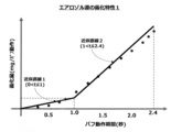
- FIGS. 3 and 4 are schematic graphs showing the atomization characteristics of the aerosol source with respect to the puff operation of the user using the suction device 100. Based on these graphs, the atomization characteristics of the aerosol source in the atomization phenomenon of the suction device 100 can be specified.
- 5A to 6B are schematic graphs showing a time-corrected model devised based on the atomization characteristics of the aerosol source according to the first embodiment.
- the graph in FIG. 3 shows the relationship between the puff operation period and the amount of atomization per puff operation regarding the atomization phenomenon of the suction device 100 using the sample flavor source.
- An example is shown.
- the horizontal axis shows the puff operation period (seconds) per puff operation. Specifically, the puff operation period is a period from the start to the end of the puff operation.
- the vertical axis shows the amount of atomization per puff operation, that is, the amount of aerosol source consumed (mg / puff operation).
- the atomization amount is an amount obtained by subtracting the weight of the aerosol source at the end of the puff operation from the weight of the aerosol source at the start of the puff operation.
- the suction sensor and the timer detect the start and end of the puff operation, and the timer determines the continuous period from the start to the end of the puff operation.
- Data can be acquired by measuring.
- the amount of atomization on the vertical axis can be obtained by measuring the weight of the aerosol source at the start of the puff operation and the end of the puff operation with, for example, a weight sensor and calculating the difference.
- FIG. 3 13 sample points measured in the atomization phenomenon are plotted.
- an actual atomization curve based on these 13 sample points and a theoretical atomization straight line are shown.
- the theoretical atomization straight line is created by connecting the origin and the sample point farthest from the origin (with the longest puff operation period of 2.4 seconds). This is based on the idea that the amount of atomization increases in proportion to the suction time in the puff operation.
- the actual atomization curve is not proportional to the puff operation period and the actual atomization amount, unlike the theoretical atomization straight line.
- the puff operation period is up to about 2.4 seconds
- at least the actual atomization amount is smaller than the theoretical atomization amount.
- the difference between the two increases with time until the puff operation period is about 1 second (difference 1), and then decreases with time (difference 2). This is because, in the atomization phenomenon of the suction device 100, a certain rise time is required from the start of heating the heater at the start of the puff operation until the temperature reaches a suitable temperature at which atomization is possible. Due to.
- the graph of FIG. 4 shows the operation interval between two consecutive puff operations and the amount of atomization atomized through the two consecutive puff operations regarding the atomization phenomenon of the suction device 100 using the sample flavor source.
- the horizontal axis indicates the puff operation interval (seconds) between two consecutive puff operations. Specifically, the puff operation interval is the period from the end of the first puff operation to the start of the next second puff operation.
- the vertical axis shows the amount of atomization of the aerosol source atomized through two consecutive puffing operations, that is, the consumption amount (mg / 2 puffing operation). Specifically, the amount of atomization of the aerosol source is the amount obtained by subtracting the weight of the aerosol source at the end of the second puff operation from the weight of the aerosol source at the start of the first puff operation.
- the puff operation interval is detected by the suction sensor at the start of the puff operation and the end of the puff operation, and is between the end of the first puff operation and the start of the next second puff operation.
- Data can be acquired by measuring the time with a timer.
- the amount of atomization is obtained by measuring the weight of the aerosol source at the start of the first puff operation and the end of the second puff operation with a weight sensor, for example, and calculating the difference. Can be done.
- FIG. 4 nine sample points measured in the atomization phenomenon are plotted. Then, for seven data having a puff operation interval of about 10 seconds or less, a regression line by linear regression with the puff operation interval as the explanatory variable and the atomization amount as the objective variable is shown. As shown, there is a negative correlation here. That is, in the actual atomization phenomenon, the shorter the puff operation interval, the larger the amount of atomization of the aerosol source to be atomized (about 8.8 mg to 9.3 mg). On the other hand, when the puff operation interval is larger than about 10 seconds, the amount of atomization of the aerosol source is substantially constant and stable (about 8.1 mg: dotted line).
- the two atomization characteristics of the aerosol source in advance and reflect them in the control of the estimation of the remaining amount level. Specifically, by incorporating a control method that corrects the value of the puff operation period based on the two atomization characteristics, it is possible to further improve the estimation accuracy of the remaining amount of the aerosol source and / or the remaining amount of the flavor source. it can.
- the two atomization characteristics (atomization characteristics 1 and 2) of the aerosol source are summarized below.
- Atomization characteristic 1 is specified based on the relationship between the sample operation period of the puff operation and the amount of atomization (Fig. 3).
- the amount of atomization of the actual aerosol source is smaller than the theoretical amount of atomization.
- the puff operation period is about 1 second or less, the difference between the theoretical value and the measured value increases with the size of the puff operation period.
- the puff operation period is about 1 second or more, the difference between the theoretical value and the measured value decreases with the size of the puff operation period. If the value of the actual puff operation period is applied as it is to the estimation of the remaining amount level, the amount of atomization that is larger than the actual value can be estimated. Therefore, the value of the puff operation period is corrected to be somewhat smaller, and the aerosol source It is good to estimate the remaining level.
- the actual amount of atomization of the aerosol source is smaller than the theoretical amount of atomization. That is, in the case of the suction device 100B in which the cartridge 104 and the capsule 126 are separate elements, the actual amount of aerosol passing through the flavor source held in the capsule 126 is smaller than the theoretical amount of aerosol. That is, the accuracy of estimating the remaining amount of the aerosol source and the remaining amount of the flavor source can be further improved by adopting a configuration in which the value of the puff operation period is corrected to be somewhat smaller to estimate the remaining amount level of the flavor source. ..
- Atomization characteristic 2 is specified based on the relationship between the sample operation interval between two consecutive puff operations and the amount of atomization of the aerosol source (FIG. 4).
- the puff operation interval is about 10 seconds or less, a negative correlation occurs between the puff operation interval and the amount of atomization of the aerosol source. Therefore, as the puff operation interval increases, the amount of atomization of the aerosol source decreases. To do. That is, when the puff operation interval is 10 seconds or less, if the value of the actual puff operation period is applied as it is to the estimation of the remaining amount level, the atomization amount smaller than the actual amount may be estimated. That is, it is advisable to correct the value of the puff operation period somewhat larger to estimate the residual level of the aerosol source.
- the atomization amount smaller than the actual amount may be estimated. .. That is, with respect to the case where the cartridge 104 and the capsule 126 of the suction device 100B are different elements, the amount of aerosol passing through the flavor source held in the capsule 126 may be estimated to be smaller than the actual amount. Therefore, the accuracy of estimating the remaining amount of the aerosol source and the remaining amount of the flavor source can be further improved by adopting a configuration in which the value of the puff operation period is corrected to some extent and the remaining amount level of the flavor source is estimated. it can.
- the power supply unit of the suction device 100 dynamically corrects the detection time, which is the time during which the detected puff operation continues, according to the atomization characteristics 1 and 2 of the aerosol source in the puff operation. Through this, it is configured to accurately estimate the remaining amount level. That is, by estimating the puff operation period and the cumulative puff operation period more accurately than the actually detected puff operation detection time, it is possible to estimate an appropriate remaining amount level for the flavor source and / or the aerosol source. .. This provides appropriate consumption level estimation, replacement decisions, and notifications for cartridges and / or capsules.
- FIGS. 5A to 6B Time correction model generated based on atomization characteristics
- the detection time of the detected puff operation is corrected according to the atomization characteristics 1 and 2 of the aerosol source.
- the generation method of the time correction models 1 and 2 will be described in detail.
- 5A and 5B are schematic views for explaining a time correction model 1 based on the atomization characteristic 1 of the aerosol source.
- 6A and 6B are schematic views for explaining the time correction model 2 based on the atomization characteristic 2 of the aerosol source.
- FIG. 5A 13 sample points of the puff operation period and the amount of atomization shown in the graph of FIG. 3 are used.
- the atomization characteristic 1 two approximate straight lines that are approximated before and after the puff operation period of 1.0 second are shown.
- the puff operation period is between 0 seconds and 1.0 and between 1.0 seconds and 2.4 seconds by approximating with two consecutive straight lines (approximate straight lines 1 and 2). )
- the atomization property 1 of the aerosol source can be appropriately qualified.
- the slope of the approximate straight line 1 is smaller than the slope of the approximate straight line 2.
- the time correction model 1 shown in FIG. 5B is generated based on the atomization characteristic 1 of FIG. 5A.
- the horizontal axis (x-axis) shows the puff operation period (seconds)
- the vertical axis (y-axis) shows the corrected puff operation period (seconds) with respect to the puff operation period.
- the puff operation period is corrected to the corrected puff operation period.
- the atomization amount is specified by using two linear functions when the puff operation period is around 1.0 second.
- the puff operation period is corrected in order to underestimate the amount of atomization consumed according to the atomization characteristic 1 of the aerosol source, that is, so that the corrected puff operation period is smaller than the actual puff operation period. .. More specifically, in the time correction model 1, when the puff operation period is 2.4 seconds, the corrected puff operation period is 2.4 seconds (correction factor: 1.0), and the puff operation period is 1. The value (a) of the corrected puff operation period in the case of 0 seconds is set to be between 0 seconds and 1.0 seconds. Then, the time correction model 1 is generated by connecting the three points of the coordinates (0,0), (1.0, a), and (2.4, 2.4) with a straight line.
- the time correction model 1 is a function of variables x and a.
- y C 1 (x, a) (where 0 ⁇ a ⁇ 1) It is expressed as.
- a is predetermined within the range of 0 ⁇ a ⁇ 1.
- W 0 is a y-intercept of a linear function representing a straight line obtained by connecting two points of coordinates (1.0, a) and (2.4, 2.4).
- FIG. 6A is a time correction model 2 in which the atomization characteristic 2 of the aerosol source shown in FIG. 4 is further applied to the time correction model 1 shown in FIG. 5B.
- the function C 2 (x, int ) of the time correction model 2 is generated by adjusting the function C 1 (x, a) of the time correction model 1.
- the puff operation period is corrected so that the period is larger than the actual puff operation period.
- the function C 2 (x, int ) of the time correction model 2 is a function in which two variables are the puff operation period (x) and the puff operation interval ( int ).
- ⁇ 0 ⁇ x ⁇ 1
- the function y C 2 (x, 0) when the puff operation interval tint is set to 0 seconds can be obtained by using the T 0 .
- the adjustment amount is a value of t 0 and prorated t int pair (10-t int), which corresponds to the corresponding amount of (10-t int).
- y a ⁇ (x + T 0 ⁇ (1-t int / 10))
- ⁇ W 0 ((2.4-a) /1.4) ⁇ (x + T 0 ⁇ (1-t int / 10))-(2.4 / 1.4) ⁇ (1-a) (However, 0 ⁇ a ⁇ 1) Is expressed by two linear functions (Equation 5).
- T 0 is as expressed by the formula 3.
- the corrected puff operation period y is the puff. It can be obtained from the operation period x, the puff operation interval int , and the constant a. That is, the sensor 112 detects the puff operation of the suction device 100 by the user, measures the detection time which is the time during which the detected puff operation continues, and puffs the operation between two consecutive puff operations. by measuring the interval may be substituted for puff operation period of the formula 5 x and puffs operation interval t int.
- the constant a may be appropriately set in advance within the range of 0 ⁇ a ⁇ 1 at the time of design, for example, according to the device characteristics of the suction device 100.
- FIG . 7 is mounted by the control unit 106 and the sensor 112 with respect to the power supply unit 102 provided in the suction device 100 according to the first embodiment.
- An example of the main functional blocks to be implemented and an example of the main information stored in the memory 114 are shown.
- the control unit 106 cooperates with the sensor 112 and the memory 114 to control various operations related to the estimation of the remaining amount level of the flavor source and / or the aerosol source.
- Examples of functional blocks of the control unit 106 are a puff detection time measurement unit 106a, a puff operation interval measurement unit 106b, a detection time correction unit 106c, a detection time accumulation unit 106d, a suction component source remaining amount level estimation unit 106e, and a notification instruction unit. Includes 106f.
- An example of a functional block of the sensor 112 includes a puff detection unit 112a and an output unit 112b.
- Examples of information stored in the memory 114 include time information such as cartridge maximum consumption time information 114a, capsule maximum consumption time information 114b, time correction model information 114c, and cumulative detection time information 114d.
- the puff detection time measuring unit 106a measures the detection time (period) of the puff operation detected by the puff detecting unit 112a. Specifically, the puff detection time measuring unit 106a may continuously measure the period from the start to the end of the puff operation detected by the puff detection unit 112a with a timer.
- the puff operation interval measuring unit 106b measures the operation interval between two consecutive puff operations. Specifically, the puff operation interval measuring unit 106b is from the end of the first puff operation out of the two consecutive puff operations detected by the puff detection unit 112a to the start of the next second puff operation. The time between them may be continuously measured with a timer.
- the detection time correction unit 106c corrects the detection time of the puff operation according to the time correction model defined based on the atomization characteristics of the aerosol source in the puff operation.
- the detection time accumulation unit 106d accumulates the detection time of the corrected puff operation and calculates the cumulative detection time.
- the suction component source residual amount level estimation unit 106e estimates the residual amount level of the flavor source and / or the aerosol source based on the accumulated detection time. Further, when the cumulative detection time reaches a predetermined threshold time, it is determined that the remaining amount of the flavor source and / or the aerosol source is insufficient.
- the notification unit 106f instructs the notification unit 108 to perform a notification operation according to the result of estimating the remaining amount level of the flavor source and / or the aerosol source.
- the suction component source remaining amount level estimation unit 106e determines that the remaining amount is insufficient, the notification unit 108 is notified of the insufficient amount accordingly.
- the puff detection unit 112a detects a puff operation and / or a non-puff operation by the user by using a suction sensor such as a microphone capacitor.
- the output unit 112b outputs various information detected by the sensor 112 to the control unit 106 or stores it in the memory 114.
- the cartridge maximum consumption time information 114a is time information (eg, 1,000 seconds) corresponding to the maximum consumption of the aerosolgen and / or flavor source held in the cartridge reservoir 116. is there.
- the capsule maximum consumption time information 114b is time information (for example, 100 seconds) corresponding to the maximum consumption of the flavor source 128 held in the capsule of the suction device 100B. These may be preset, for example, when designing cartridges and capsules. Further, in the flavor source 128 held in the capsule, it is preferable to set a different value for each type.
- the time-corrected model information 114c is information on the atomization characteristics of the aerosol source described above and information on a time-correction model based on the atomization characteristics of the aerosol source.
- the time-corrected model information 114c includes 1.0 second and 2.4 second information regarding the puff operation period shown in FIG. 3, 10 second information regarding the puff operation interval shown in FIG. 4, and FIG. 5B.
- Information on the set value a and the function y C 1 (x, a) of the time correction model, the value of the adjustment amount T 0 ⁇ (1-t int / 10) shown in FIG. 6B, and the function of the time correction model.
- the cumulative detection time information 114d is information on the cumulative detection time accumulated by the detection time accumulation unit 106d, and is updated each time the user puffs.
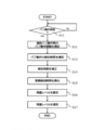
- FIGS. 8 and 9 are examples of a processing flow in which the control unit 106 controls the operation of the power supply unit 102 provided in the suction device 100 according to the first embodiment. Is. FIG. 8 is an example of the entire processing flow in which the control unit 106 controls the operation of the power supply unit 102. FIG. 9 is an example of a detailed processing flow relating to the correction of the detection time of the puff operation.
- step S11 the control unit 106 causes the puff detection unit 112a of the sensor to detect the puff operation by the user. Specifically, it is determined whether or not the puff operation consisting of the start and end of the puff operation is detected by the puff detection unit 112a.
- step S11: Yes the puff operation is detected
- step S12 the puff operation interval measuring unit 106b of the control unit measures the puff operation interval between two consecutive puff operations.
- step S13 the puff detection time measuring unit 106a of the control unit measures the detection time of the latest puff operation.
- the detection time here is the time during which the detected puff operation continues.
- the operation order of step S12 and step S13 may be reversed, or any other operation may be included between them.
- step S14 the detection time correction unit 106c of the control unit corrects the detection time of the puff operation measured in step S13 based on the value of the characteristic parameter associated with the puff operation.
- Step S14 is based on the above-mentioned atomization characteristics of the aerosol source in the suction device 100. Specifically, a time correction model 1 (FIGS. 3, 5A, and 5B) based on the atomization characteristic 1 of the aerosol source is used, and the characteristic parameter in this case includes the detection time of the puff operation. Similarly, a time-corrected model 2 (FIGS. 4, 6A, and 6B) based on the aerosol source atomization characteristic 2 is also used, in which characteristic parameter includes the puffing interval.
- the information of the time correction models 1 and 2 based on the atomization characteristics 1 and 2 is stored in the memory 114 in advance as a part of the time correction model information 114c.
- step S15 the detection time accumulation unit 106d of the control unit calculates the cumulative detection time by accumulating the detection time corrected in step S14.
- the cumulative detection time is stored in the memory 114 as a part of the cumulative detection time information 114d each time it is updated.
- the suction component remaining amount level estimation unit 106e of the control unit estimates the remaining amount level of the flavor source and / or the aerosol source based on the cumulative detection time calculated in step S15.
- the remaining amount level may be calculated as a puff time (seconds) permitted in the future, or may be calculated as a percentage (%) of the puff time, in any embodiment.
- the cumulative detection time reaches a predetermined threshold time, it may be determined that the remaining amount of the flavor source and / or the aerosol source is insufficient.
- the predetermined threshold time is stored in the memory 114 in advance as a part of the capsule maximum consumption time information 114b (for example, 100 seconds) and / or a part of the cartridge maximum consumption time information 114a (for example, 1,000 seconds). ..
- step S17 the notification instruction unit 106f of the control unit instructs the notification unit 108 to notify the remaining amount level estimated in step S16.
- various modes of notification may be given to the user by lighting an LED, displaying on a display, uttering from a speaker, vibrating with a vibrator, and any combination thereof.
- the target for estimating the remaining amount level can be flexibly set according to the structures of the suction devices 100A and B. Specifically, both the capsule 126 and the cartridge 104 need only convert the amount of the suction component source into time information and store it as the capsule maximum consumption time information 114b and / or the cartridge maximum consumption time information 114a. At the time of the operation of estimating the remaining amount level, the control unit 106 needs to handle only such time information, which is efficient.
- step S14 includes a processing operation of the time correction 1 shown in steps S141 to S143 and the time correction 2 shown in steps S144 to S146.
- step S141 whether puffs operation interval t int two consecutive puffs operation measured in step S12 in FIG. 8 is less than 10 seconds is determined.
- the determination process is associated with the atomization characteristic 2 of the aerosol source shown in FIG. 4 and is associated with the time correction model 2 based on the atomization characteristic 2 shown in FIGS. 6A and 6B.
- step S142 the above-mentioned adjustment amount (T 0 ⁇ (1-t int / 10)) regarding the detection time of the puff operation is calculated.
- step S143 the adjustment amount may be simply set to 0 without performing the correction.
- t crt1 t And it is sufficient.
- the adjustment amount is set to 0 because when the puff operation interval is made larger than 10 seconds, there is a negative correlation between the puff operation interval and the atomization amount due to the puff operation. Is not generated (dotted line in FIG. 4), and therefore, it is not necessary to perform correction based on the time correction model 2.
- step S144 it is determined whether or not the detection period t pf of the puff operation is 1 second or less.
- the determination process is associated with the atomization characteristic 1 of the aerosol source shown in FIGS. 3 and 5A, and is associated with the time correction model 1 based on the atomization characteristic 1 shown in FIG. 5B.
- step S146 correction is performed based on the case of 1 ⁇ x ⁇ 2.4 in Equation 5.
- the detection time tpf of the puff operation is appropriately corrected through the time correction models 1 and 2 shown in FIG.
- the detection time is more realistic, that is, the actual consumption of the aerosol source and the amount of aerosol that actually passed through the flavor source (in other words, the amount of flavor actually imparted by the flavor source).
- the detected detection time can be calculated. As a result, the accuracy at the time of estimating the remaining amount level can be improved.
- the operation of the suction device 100 can be optimized by dynamically grasping the remaining amount level of the suction component source. That is, it is possible to extend the life of the suction device, reduce the frequency of disposal of the suction device, the battery, the suction article, and the like, and prevent unnecessary replacement of the suction component source to provide an environment-friendly suction device. Therefore, the first embodiment is advantageous in that it also considers energy saving and environmental protection.
- the operation method of the power supply unit 102 provided in the suction device according to the first embodiment is described in the block diagrams shown in FIGS. 1A, 1B and 7, the graphs shown in FIGS. 2 to 6B, and the graphs shown in FIGS. 2 to 6B. It has been described with reference to the processing flow shown in FIGS. 8 and 9.
- the first embodiment can also be implemented as a program that causes the processor to execute the processing flow shown in FIGS. 8 and 9 to the power supply unit 102. Understood. Similarly, it is understood that it can also be implemented as a computer-readable storage medium that stores the program.
- FIGS. 10 to 13B Time correction model generated based on atomization characteristics
- the detection time of the detected puff operation is corrected according to the atomization characteristics 1a and 2a of the aerosol source.
- the generation method of the time correction models 1A and 2A will be described.
- 10 and 12 are schematic views for explaining the atomization characteristics 1a and 2a of the aerosol source.
- 11A and 11B are schematic views for explaining a time correction model 1A based on the aerosol source atomization characteristic 1a
- FIGS. 13A and 13B are time based on the aerosol source atomization characteristic 2a. It is the schematic for demonstrating the correction model 2A.
- FIG. 10 shows the actual mist using 13 sample points of the puff operation period and the amount of atomization of the aerosol source (and / or flavor source), similar to the atomization characteristic 1 of the aerosol source shown in FIG. It is a graph which showed the chemical line as a polygonal line, and constitutes the atomization characteristic 1a.
- the value of the atomization amount at the sample point is calculated by measuring the atomization amount of the aerosol source a plurality of times for each predetermined puff operation period and calculating the average thereof.
- the actual amount of atomization of the aerosol source is smaller than the theoretical amount of atomization.
- the value of the actual puff operation period is applied as it is to the estimation of the remaining amount level and calculated with the ideal value, the amount of atomization can be estimated larger than the actual amount, and a large amount of aerosol is used for the estimation.
- the source may be left over. That is, it is preferable to correct the value of the puff operation period to be somewhat smaller and then use it for estimating the remaining amount level.
- the maximum value of the puff operation period is set to 2.4 seconds according to the atomization characteristic 1 (FIG. 3) of the aerosol source.
- 2.4 seconds is the value at which the consumption efficiency of the aerosol source is the highest in the suction device.
- this value is only an example, and it is preferable to set an ideal value having the highest consumption efficiency of the aerosol source according to the device characteristics and / or design of the suction device.
- FIG. 11A shows an example of a time-corrected model 1A ID based on the atomization characteristic 1a of the aerosol source.
- the time correction model 1A ID corresponds to the experimental atomization characteristic 1a shown in FIG. 10, and is an ideal time correction model.
- the horizontal axis (x-axis) shows the puff operation period (seconds)
- the vertical axis (y-axis) shows the corrected puff operation period (seconds) with respect to the puff operation period.
- the corrected puff operation period is set for each predetermined puff operation period based on the ideal value of 2.4 seconds, which is the highest consumption efficiency of the aerosol source, according to the atomization characteristic 1a of FIG. It is better to decide according to the ratio of the relative amount of atomization.
- the atomization amount when the puff operation period is 2.4 seconds is A 2.4 mg
- the atomization amount when the puff operation period is 1.2 seconds is A. It shall be 1.2 mg.
- the corrected puff operation period (y) when the puff operation period (x) is 1.2 seconds is calculated as 2.4 ⁇ A 1.2 / A 2.4. Is good.
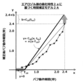
- FIG. 11B shows an example of a time correction model 1A based on the atomization characteristic 1a.
- the time correction model 1A is theoretically defined with respect to the ideal time correction model 1A ID of FIG. 11A.
- the horizontal axis (x-axis) shows the puff operation period (seconds)
- the vertical axis (y-axis) shows the corrected puff operation period (seconds) with respect to the puff operation period. That is, the time correction model 1A of FIG. 11B is a model based on the puff operation period.
- the value of the corrected puff operation period (y) is maintained at 2.4 seconds when the puff operation period (x) is 2.4 seconds. It defines a function that correlates with the time-corrected model 1A ID of 11A.
- the constant T 10 is preferably a value less than 1.0. Specifically, it is preferable to obtain it experimentally in consideration of the device characteristics of the suction device 100 and set it in the memory 114.
- the device characteristics here are not limited to the cartridge characteristics, the heater heating characteristics, and the loss characteristics due to the adhesion of the aerosol source into the mouthpiece and / or the capsule.
- the value of the puff operation period (x) is in the vicinity of T 10
- the value of the puff operation period (y) after correction by the time correction model 1A is smaller than that by the time correction model 1A ID (dotted line).
- T 10 is set to a value less than 1.0, it is not necessary to assume the effect of the correction in the first place (described later).
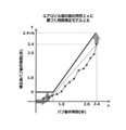
- FIG. 12 shows five sample points of a predetermined two consecutive puff operation intervals and an atomization amount of the aerosol source (and / or flavor source), similar to the atomization characteristic 2 of the aerosol source shown in FIG. Is a graph showing an actual atomization line as a polygonal line using the above, and constitutes the atomization characteristic 2a.
- the value of the atomization amount at the sample point is a measurement of the atomization amount of the aerosol source at every 2 second puff operation interval by an experiment.
- the puff operation interval is measured by a sensor and a timer. In FIG. 12, the puff operation period is fixed at 2.4 seconds for measurement.
- the amount of atomization of the aerosol source with respect to the puff operation interval largely depends on the device characteristics, and there are large individual differences. Therefore, in the example of FIG. 12, what was measured using three individuals 1 to 3 is plotted. Further, as in the first embodiment, in the second embodiment as well, according to the atomization characteristic 2 (FIG. 4) of the aerosol source, the reference value of the puff operation interval between two consecutive puff operations is set to 10 seconds. .. 10 seconds is a value at which the amount of atomization of the aerosol source consumed stabilizes with respect to the puff operation interval. However, this is only an example, and it is preferable to set a suitable value determined by experiment according to the device characteristics and / or setting of the suction device.
- the puff operation interval when the puff operation interval is about 10 seconds or less, a negative correlation occurs between the puff operation interval and the atomization amount of the aerosol source (and / or flavor source). .. That is, as the puff operation interval increases, the amount of atomization of the aerosol source decreases. In this regard, when the puff operation interval is 10 seconds or less, if the value of the actual puff operation period is applied to the estimation of the remaining amount level as it is, the atomization amount smaller than the actual amount may be estimated.
- the aerosol source may be insufficient. That is, it is preferable to correct the value of the puff operation period to some extent and then use it for estimating the remaining amount level.
- FIG. 13A shows an example of a time-corrected model 2A DIF based on the atomization characteristic 2a of the aerosol source of FIG.
- the horizontal axis (v-axis) shows two consecutive puff operation intervals (seconds)
- the vertical axis (w-axis) shows the corrected difference puff operation period (seconds) with respect to the puff operation period.
- FIG. 13A shows only two data groups of individuals 1 and 2 shown in the atomization characteristic 2a of FIG. 12 (dotted line and broken line), and the data group of individual 3 is omitted. ..
- a time-corrected model 2A DIF is defined for each of these individual data groups (solid line).
- the corrected difference puff operation period (seconds) of each individual sample point is set for each predetermined puff operation interval shown in FIG. 12 based on the value of the puff operation interval being 10 seconds. It should be determined according to the ratio of the relative amount of atomization. For example, in the atomization characteristic 2a of the individual 2 in FIG. 12, the atomization amount when the puff operation period is 10 seconds is B 10 mg, and the atomization amount when the puff operation period is 2 seconds is B 2 mg. And. In this case, in FIG. 13A, the corrected difference puff operation period with respect to the puff operation interval of 2 seconds is preferably calculated as 10 ⁇ (B 2- B 10 ) / B 10 . When the value of the puff operation interval is larger than 10 seconds, the corrected difference puff operation period is preferably set to 0.
- the time correction model 2A DIF of FIG. 13A is for calculating the corrected difference puff operation period calculated based on the puff operation interval as the adjustment time based on the two consecutive puff operation intervals. Then, the calculated adjustment time is added to the detection time in the time correction model 1A based on the atomization characteristic 1a of the aerosol source, so that the time correction model 2A based on the atomization characteristic 2a is defined.
- the time-corrected model 2A DIF based on the atomization characteristic 2a includes a region including all sample points (data groups) of a plurality of individuals and a region other than that in the vw plane (first quadrant) of FIG. 13A. It is better to specify it as a linear function that classifies.
- the slope p ( ⁇ 0) is a constant determined in advance by an arbitrary method based on a data group of a plurality of individuals, and is set in the memory 114.
- the time correction model 2A DIF By applying the time correction model 2A DIF based on the atomization characteristic 2a in this way, it is possible to determine the adjustment time, which is the corrected difference puff operation period (w), with respect to the value of the puff operation interval (v). .. Then, by combining the time correction model 2A DIF with the time correction model 1A described above, the time correction model 2A based on the atomization characteristic 2a, which will be described next, is defined. As a result, the value of the adjustment time is added to the value of the corrected puff operation period (y), and the value of the corrected puff operation period can be appropriately corrected based on the value of the puff operation period.
- FIG. 13B shows an example of a time correction model 2A based on such atomization characteristic 2a.
- the horizontal axis (x-axis) shows the puff operation period (seconds)
- the vertical axis (y-axis) shows the corrected puff operation period (seconds) with respect to the puff operation period.
- the value of the puff operation period (x) is 2.4 seconds
- the corrected difference puff operation period (w) calculated based on the puff operation interval (v) according to the time correction model 2A DIF .
- the value is added to the puff operation period of 2.4 seconds as the adjustment time b.
- the function of the time correction model 2A that calculates the value of the corrected puff operation period (y) is defined.
- the puff operation interval (v) is represented by an int .
- the function C 30 (x, int ) of the time correction model 2A is a function of the puff operation period x and the puff operation interval int . Can be expressed as.
- the time correction models 1A and 2A are defined based on the atomization characteristics 1a and 2a of the aerosol source.
- Equation 8 ' after correction puffs operation period y is be calculated from the puff operating period x and puffs operation interval t int, and the values of the constants p and T 10 Can be done. That is, in response to the sensor 212 detecting the puff operation of the suction device 100 by the user, between the detection time, which is the puff operation period in which the detected puff operation continues, and the two consecutive puff operations. by measuring the puff operation interval, is obtained after correction puffs operation period by substituting puff operation period x and puffs operation interval t int equation 8 '.
- the constants p and T 10 may be appropriately set at the time of design, for example, according to the device characteristics and / or design of the suction device 100.
- FIG . 14 Functional block for estimating the remaining amount level of the suction component source by the power supply unit FIG . 14 is mounted by the control unit 206 and the sensor 212 with respect to the power supply unit 202 provided in the suction device 100 according to the second embodiment.
- the control unit 206 cooperates with the sensor 212 and the memory 214 to control various operations related to the estimation of the remaining amount level of the flavor source and / or the aerosol source.
- Examples of functional blocks of the control unit 206 are the puff detection time measurement unit 206a, the puff operation interval measurement unit 206b, the detection time correction unit 206c, the detection time accumulation unit 206d, the suction component source remaining amount level estimation unit 206e, and the notification instruction unit. Includes 206f.
- Examples of functional blocks of the sensor 212 include a puff detection unit 212a and an output unit 212b.
- Examples of the information stored in the memory 214 include time information such as cartridge maximum consumption time information 214a, capsule maximum consumption time information 214b, time correction model information 214c, and cumulative detection time information 214d.
- the puff detection time measuring unit 206a relates to the puff operation detected by the puff detecting unit 212a, the detection time which is the puff operation period in which the detected puff operation continues, and two continuous puffs. Measure the puff movement interval between movements.
- the detection time correction unit 206c corrects the detection time of the puff operation by using the time correction model based on the characteristic parameter associated with the puff operation.
- the characteristic parameters include, in one example, the puff operation period and / or the puff operation interval.
- the detection time accumulation unit 206d accumulates the detection time of the corrected puff operation and calculates the cumulative detection time.
- the suction component source residual amount level estimation unit 206e estimates the residual amount level of the flavor source and / or the aerosol source based on the accumulated detection time. Further, when the cumulative detection time reaches a predetermined threshold time, it is determined that the remaining amount of the flavor source and / or the aerosol source is insufficient.
- the notification unit 206f instructs the notification unit 108 to perform a notification operation according to the result of estimating the remaining amount level of the flavor source and / or the aerosol source. In particular, when the suction component source remaining amount level estimation unit 206e determines that the remaining amount is insufficient, the notification unit 108 is notified of the insufficient amount accordingly.
- FIGS. 15 and 16 are examples of a processing flow in which the control unit 206 controls the operation of the power supply unit 202 provided in the suction device 100 according to the second embodiment.
- FIG. 15 is an example of the entire processing flow in which the control unit 206 controls the operation of the power supply unit 202.
- FIG. 16 is an example of a detailed processing flow relating to the correction processing S24 of the detection time of the puff operation. Since the flow of FIG. 15 is the same as that of the first embodiment except for the step (S24) of correcting the detection time, only the outline will be described below, and detailed description will be omitted.
- step S21 the control unit 206 causes the puff detection unit 212a of the sensor to detect the puff operation by the user.
- the puff operation interval measuring unit 206b of the control unit measures the puff operation interval between two consecutive puff operations.
- the puff detection time measuring unit 206a of the control unit measures the detection time of the latest puff operation. The detection time is the puff operation period during which the detected puff operation continues, but the value is appropriately corrected by the subsequent processing.
- the detection time correction unit 206c of the control unit corrects the detection time of the puff operation measured in step S23 by using the time correction model based on the value of the characteristic parameter associated with the puff operation.
- the time correction models 1A and 2A are defined based on the atomization characteristics 1 (1a) and 2 (2a) of the aerosol source in the suction device, and the characteristic parameters are the puff operation period and two consecutive puff operation periods. Includes the puffing interval between puffing movements.
- step S25 the detection time accumulation unit 206d of the control unit calculates the cumulative detection time by accumulating the detection time corrected in step S24.
- step S26 the suction component remaining amount level estimation unit 206e of the control unit estimates the remaining amount level of the flavor source and / or the aerosol source based on the cumulative detection time calculated in step S25. Further, when the cumulative detection time reaches a predetermined threshold time, it may be determined that the remaining amount of the flavor source and / or the aerosol source is insufficient.
- step S27 the notification instruction unit 206f of the control unit instructs the notification unit 108 to notify the remaining amount level estimated in step S26. In particular, when it is determined in step S26 that the remaining amount of the flavor source and / or the aerosol source is insufficient, it is preferable to notify the notification unit 108 that the remaining amount is insufficient.
- the target for estimating the remaining amount level can be flexibly set according to the structure of the suction devices 100A and B. Specifically, both the capsule 126 and the cartridge 104 need only convert the amount of the suction component source into time information and store it as the capsule maximum consumption time information 214b and / or the cartridge maximum consumption time information 214a. At the time of the operation of estimating the remaining amount level, the control unit 206 needs to handle only such time information, which is efficient.
- step S24 is executed by the detection time correction unit 206c of the control unit.
- step S241 2 two puffs operation puff operation interval t int successive measured in step S22 in FIG. 15 is about or less than 10 seconds.
- the determination process is associated with the atomization characteristics 2 and 2a of the aerosol source shown in FIGS. 4 and 12, and the time correction model 2A DIF , 2A based on the atomization characteristics 2a shown in FIGS. 13A and 13B. Is associated with.
- t 10_crt be the corrected detection time with respect to the detection time t of the actual puff operation.
- the detected detection time after correction is based on the mathematical formula 8'in step S242.
- the puff operation interval t int is greater than 10 seconds (S241: No)
- the corrected detection time is determined in the next step S242 based on the mathematical formula 8'.
- the value of the detection time of the puff operation is appropriately corrected through the time correction models 1A and 2B shown in FIGS. 11B and 13B.
- the detection time is more realistic, that is, the actual consumption of the aerosol source and the amount of aerosol that actually passed through the flavor source (in other words, the amount of flavor actually imparted by the flavor source).
- the detected detection time can be calculated. As a result, the accuracy at the time of estimating the remaining amount level can be improved.
- the constant T 10 is introduced in the time correction model 2A based on the atomization characteristic 2a of the aerosol source, and the value of the puff operation period (x) is T 10 or less.
- the corrected puff operation period (y) is set to 0 (Formula 8 and FIG. 13B). This is because in normal puff operation by the user, the puff operation period such as less than 1.0 second is rare and difficult to assume, so even for the puff operation period such as less than 1.0 second. Based on the inventor's consideration that there is no time correction. Specifically, it is as follows.
- the corrected puff operation period (y) is set to 0 when T 10 is a value less than 1.0, whereas in this modification, the corrected puff operation period (y) is set to 0. Instead of setting it to 0 uniformly, it is set to a predetermined constant that is somewhat larger than 0. As a result, even if the puff operation period is less than 1.0 second due to a device failure, the cumulative detection time value calculated by the detection time accumulation unit 206d is accumulated. Become. That is, such a value of the cumulative detection time can be appropriately used for detecting a device defect, and the life of the device can be extended.
- FIG. 17 shows an example of a further time correction model 2B based on the atomization characteristic 2a of the aerosol source according to the modified example of the second embodiment.
- the horizontal axis (x-axis) shows the puff operation period (seconds)
- the vertical axis (y-axis) shows the corrected puff operation period (seconds) with respect to the puff operation period.
- the time correction model 2B further defines a function of the time correction model 2A shown in FIG. 13B so that when the corrected puff operation period is 0 ⁇ y ⁇ q, the value is uniformly updated to q. doing.
- the constant q should be experimentally acquired in consideration of the device characteristics of the suction device 100 and set in the memory 114.
- FIG. 18 is an example of a detailed processing flow relating to the correction processing S24a of the detection time of the puff operation according to the modified example of the second embodiment. Since steps S241a, S242a, and S243a are the same as steps S241, S242, and S243 in FIG. 16, description thereof will be omitted.
- t 10_crt C 30 (t, int ) in step S242a
- the value of t 10_crt is updated to q and output for the next step S25.
- the value of t 10_crt is set to the corrected puff operation period as it is, and is output for the next step S25.
- the value is uniformly updated to q to control the power supply unit 202.
- the load of arithmetic processing on unit 206 can be reduced, and a device abnormality can be detected.
- the operation method of the power supply unit 202 provided in the suction device according to the second embodiment and the modified example thereof is shown in the block diagrams, FIGS. 10 to 13B and FIGS. 1A, 1B and 14B. It has been described with reference to the graph shown in FIG. 17 and the processing flow shown in FIGS. 15, 16 and 18.
- the second embodiment is also implemented as a program that causes the power supply unit 202 to execute the processing flow shown in FIGS. 15, 16 and 18 when executed by the processor in the control unit 206 of the power supply unit 202. It is understood to get.
- it can also be implemented as a computer-readable storage medium that stores the program.
- FIG. 19 is a block diagram showing a configuration example of the power supply unit 300 for the suction device 100 according to the third embodiment.
- the power supply unit 300 includes a sensor 301 and a control unit 302.
- the sensor 301 corresponds to, for example, the sensor 112 shown in FIGS. 1A and 1B and the sensor 212 shown in FIG.
- the control unit 302 corresponds to, for example, the control unit 106 shown in FIGS. 1A and 1B and the sensor 206 shown in FIG.
- the sensor 301 provided in the power supply unit 300 detects the puff operation by the user.
- the control unit 302 provided in the power supply unit 300 measures the detection time, which is the puff operation period during which the puff operation detected by the sensor 301 continues. Further, the control unit 302 corrects the detection time by using each time correction model based on the atomization characteristic of the aerosol source in the puff operation, accumulates the corrected detection time, and calculates the cumulative detection time. Further, the control unit 302 estimates the residual level of the flavor source and / or the aerosol source based on the cumulative detection time.
- FIG. 20 is an example of a processing flow in which the control unit 302 controls the operation of the power supply unit 300 provided in the suction device 100 according to the third embodiment.
- the control unit 302 causes the sensor 301 to detect the puff operation by the user.
- the control unit 302 measures the detection time, which is the puff operation period during which the puff operation detected by the sensor 301 continues.
- the control unit 302 corrects the detection time by using each time correction model based on the atomization characteristic of the aerosol source in the puff operation.
- step S34 the control unit 302 accumulates the detection time corrected in S33 and calculates the cumulative detection time.
- the control unit 302 estimates the remaining amount level of the flavor source and / or the aerosol source based on the cumulative detection time calculated in S24.
- the control unit 302 corrects and accumulates the detection time of the puff operation detected by the sensor 301 based on the atomization characteristic of the aerosol source associated with the puff operation detected by the sensor 301. By doing so, the cumulative detection time is calculated. Specifically, for example, the control unit 302 sets the puff operation period and the puff operation interval (for example, the interval from the end of one puff operation to the start of the next one puff operation) detected by the sensor 301. Based on this, the detection time is increased or decreased, corrected and accumulated, and the cumulative detection time is calculated. Finally, the control unit 302 estimates the residual level of the flavor source and / or the aerosol source based on the calculated cumulative detection time. Thereby, it is possible to grasp and notify the remaining amount level of the appropriate flavor source and / or aerosol source.
- the operation of the suction device 300 can be optimized by dynamically grasping the remaining amount level of the suction component source. That is, it is possible to extend the life of the suction device, reduce the frequency of disposal of the suction device, the battery, the suction article, and the like, and prevent unnecessary replacement of the suction component source to provide an environment-friendly suction device. Therefore, the embodiment is advantageous in that it also considers energy saving and environmental protection.
- the operation method of the power supply unit 300 provided in the suction device according to the third embodiment has been described with reference to the block diagram shown in FIG. 19 and the processing flow shown in FIG. 20.
- a person skilled in the art can implement the third embodiment as a program that causes the power supply unit 300 to execute the processing flow shown in FIG. 20 when executed by the processor in the control unit 302 of the power supply unit 300. Is understood. Similarly, those skilled in the art will appreciate that it can also be implemented as a computer-readable storage medium containing the program.
- Detection time cumulative unit 106e, 206e ... Suction component source remaining amount level estimation unit, 106f, 206f ... Notification indicator, 112a, 212a ... Puff detection unit, 112b, 212b ... Output unit, 114a, 214a ... Cartridge maximum consumption time information, 114b, 214b ... Capsule maximum consumption time information, 114c, 214c ... Time correction model information, 114d, 214d ... Cumulative detection time information 300 ... Power supply unit, 301 ... sensor, 302 ... control unit
Abstract
L'invention concerne un procédé d'exploitation d'un bloc d'alimentation (202) pour un dispositif d'aspiration (100). Ledit procédé comprend : une étape consistant à détecter, au moyen d'un capteur, une opération de souffle réalisée par un utilisateur (212) ; une étape consistant à mesurer un temps de détection qui est une période d'opération de souffle pendant laquelle l'opération de souffle détectée s'est poursuivie ; une étape consistant à corriger le temps de détection mesuré à l'aide d'un modèle de correction de temps sur la base de paramètres caractéristiques associés à l'opération de souffle ; une étape consistant à cumuler des temps de détection corrigés et à calculer un temps de détection cumulé ; et une étape consistant à estimer un niveau résiduel pour la source d'élément d'aspiration sur la base du temps de détection résiduel.
Priority Applications (3)
| Application Number | Priority Date | Filing Date | Title |
|---|---|---|---|
| EP20834275.8A EP3995019A4 (fr) | 2019-07-03 | 2020-07-01 | Procédé d'exploitation de bloc d'alimentation pour dispositif d'aspiration, bloc d'alimentation pour dispositif d'aspiration et support lisible par ordinateur |
| JP2021529165A JP7253052B2 (ja) | 2019-07-03 | 2020-07-01 | 吸引装置の電源ユニットを動作させる方法、吸引装置の電源ユニット、及びコンピュータ可読媒体 |
| US17/532,462 US20220079244A1 (en) | 2019-07-03 | 2021-11-22 | Method for operating power supply unit for suction device, power supply unit for suction device, and computer-readable medium |
Applications Claiming Priority (2)
| Application Number | Priority Date | Filing Date | Title |
|---|---|---|---|
| JP2019-124308 | 2019-07-03 | ||
| JP2019124308 | 2019-07-03 |
Related Child Applications (1)
| Application Number | Title | Priority Date | Filing Date |
|---|---|---|---|
| US17/532,462 Continuation US20220079244A1 (en) | 2019-07-03 | 2021-11-22 | Method for operating power supply unit for suction device, power supply unit for suction device, and computer-readable medium |
Publications (1)
| Publication Number | Publication Date |
|---|---|
| WO2021002392A1 true WO2021002392A1 (fr) | 2021-01-07 |
Family
ID=74101369
Family Applications (1)
| Application Number | Title | Priority Date | Filing Date |
|---|---|---|---|
| PCT/JP2020/025857 WO2021002392A1 (fr) | 2019-07-03 | 2020-07-01 | Procédé d'exploitation de bloc d'alimentation pour dispositif d'aspiration, bloc d'alimentation pour dispositif d'aspiration et support lisible par ordinateur |
Country Status (4)
| Country | Link |
|---|---|
| US (1) | US20220079244A1 (fr) |
| EP (1) | EP3995019A4 (fr) |
| JP (1) | JP7253052B2 (fr) |
| WO (1) | WO2021002392A1 (fr) |
Cited By (1)
| Publication number | Priority date | Publication date | Assignee | Title |
|---|---|---|---|---|
| WO2023053183A1 (fr) | 2021-09-28 | 2023-04-06 | 日本たばこ産業株式会社 | Procédé de fonctionnement pour dispositif d'inhalation, programme et dispositif d'inhalation |
Families Citing this family (1)
| Publication number | Priority date | Publication date | Assignee | Title |
|---|---|---|---|---|
| EP4305987A1 (fr) * | 2022-07-11 | 2024-01-17 | Em-tech. Co., Ltd. | Dispositif de génération d'aérosol de mesure de quantité résiduelle |
Citations (11)
| Publication number | Priority date | Publication date | Assignee | Title |
|---|---|---|---|---|
| JP2014501105A (ja) | 2010-12-24 | 2014-01-20 | フィリップ・モーリス・プロダクツ・ソシエテ・アノニム | 液体基質の減少判定手段を有するエアロゾル生成システム |
| JP2014501107A (ja) | 2010-12-24 | 2014-01-20 | フィリップ・モーリス・プロダクツ・ソシエテ・アノニム | 液体気質の消費を取り扱う手段を有するエアロゾル生成システム |
| JP2015531600A (ja) | 2012-09-11 | 2015-11-05 | フィリップ・モーリス・プロダクツ・ソシエテ・アノニム | 電気ヒーターを制御して温度を制限する装置および方法 |
| JP2016525367A (ja) | 2013-07-30 | 2016-08-25 | スマート チップ マイクロエレクトロニック シーオー.リミテッド | 電子喫煙装置および香り付き蒸気発生装置 |
| WO2017057286A1 (fr) * | 2015-09-30 | 2017-04-06 | 日本たばこ産業株式会社 | Inhalateur d'arôme de type sans combustion et unité d'atomisation |
| JP2017192393A (ja) * | 2014-05-02 | 2017-10-26 | 日本たばこ産業株式会社 | 非燃焼型香味吸引器及びコンピュータ読取り可能媒体 |
| JP2017532011A (ja) * | 2014-08-26 | 2017-11-02 | ニコベンチャーズ ホールディングス リミテッド | 電子エアロゾル供給装置 |
| JP2017538410A (ja) | 2014-12-05 | 2017-12-28 | ジュール・ラブズ・インコーポレイテッドJuul Labs, Inc. | 調整された投与量の制御 |
| KR20180070443A (ko) * | 2016-12-16 | 2018-06-26 | 주식회사 케이티앤지 | 퍼프 인식을 통한 적응적인 피드백을 제공하는 에어로졸 생성 디바이스 및 방법 |
| WO2018224823A1 (fr) * | 2017-06-09 | 2018-12-13 | Nicoventures Holdings Limited | Système de fourniture d'aérosol électronique |
| JP2019500896A (ja) | 2015-11-17 | 2019-01-17 | フィリップ・モーリス・プロダクツ・ソシエテ・アノニム | 自己起動式電気ヒーターを備えたエアロゾル発生システム |
Family Cites Families (3)
| Publication number | Priority date | Publication date | Assignee | Title |
|---|---|---|---|---|
| EP3508083B1 (fr) * | 2010-08-24 | 2021-07-14 | JT International S.A. | Dispositif d'inhalation comprenant des commandes d'usage de substance |
| MY189739A (en) * | 2014-05-02 | 2022-02-28 | Japan Tobacco Inc | Non-burning-type flavor inhaler |
| CN110545682A (zh) * | 2017-04-11 | 2019-12-06 | 韩国烟草人参公社 | 提供基于抽吸识别的适应性反馈的气溶胶生成设备及方法 |
-
2020
- 2020-07-01 WO PCT/JP2020/025857 patent/WO2021002392A1/fr unknown
- 2020-07-01 EP EP20834275.8A patent/EP3995019A4/fr active Pending
- 2020-07-01 JP JP2021529165A patent/JP7253052B2/ja active Active
-
2021
- 2021-11-22 US US17/532,462 patent/US20220079244A1/en active Pending
Patent Citations (11)
| Publication number | Priority date | Publication date | Assignee | Title |
|---|---|---|---|---|
| JP2014501105A (ja) | 2010-12-24 | 2014-01-20 | フィリップ・モーリス・プロダクツ・ソシエテ・アノニム | 液体基質の減少判定手段を有するエアロゾル生成システム |
| JP2014501107A (ja) | 2010-12-24 | 2014-01-20 | フィリップ・モーリス・プロダクツ・ソシエテ・アノニム | 液体気質の消費を取り扱う手段を有するエアロゾル生成システム |
| JP2015531600A (ja) | 2012-09-11 | 2015-11-05 | フィリップ・モーリス・プロダクツ・ソシエテ・アノニム | 電気ヒーターを制御して温度を制限する装置および方法 |
| JP2016525367A (ja) | 2013-07-30 | 2016-08-25 | スマート チップ マイクロエレクトロニック シーオー.リミテッド | 電子喫煙装置および香り付き蒸気発生装置 |
| JP2017192393A (ja) * | 2014-05-02 | 2017-10-26 | 日本たばこ産業株式会社 | 非燃焼型香味吸引器及びコンピュータ読取り可能媒体 |
| JP2017532011A (ja) * | 2014-08-26 | 2017-11-02 | ニコベンチャーズ ホールディングス リミテッド | 電子エアロゾル供給装置 |
| JP2017538410A (ja) | 2014-12-05 | 2017-12-28 | ジュール・ラブズ・インコーポレイテッドJuul Labs, Inc. | 調整された投与量の制御 |
| WO2017057286A1 (fr) * | 2015-09-30 | 2017-04-06 | 日本たばこ産業株式会社 | Inhalateur d'arôme de type sans combustion et unité d'atomisation |
| JP2019500896A (ja) | 2015-11-17 | 2019-01-17 | フィリップ・モーリス・プロダクツ・ソシエテ・アノニム | 自己起動式電気ヒーターを備えたエアロゾル発生システム |
| KR20180070443A (ko) * | 2016-12-16 | 2018-06-26 | 주식회사 케이티앤지 | 퍼프 인식을 통한 적응적인 피드백을 제공하는 에어로졸 생성 디바이스 및 방법 |
| WO2018224823A1 (fr) * | 2017-06-09 | 2018-12-13 | Nicoventures Holdings Limited | Système de fourniture d'aérosol électronique |
Non-Patent Citations (1)
| Title |
|---|
| See also references of EP3995019A4 |
Cited By (1)
| Publication number | Priority date | Publication date | Assignee | Title |
|---|---|---|---|---|
| WO2023053183A1 (fr) | 2021-09-28 | 2023-04-06 | 日本たばこ産業株式会社 | Procédé de fonctionnement pour dispositif d'inhalation, programme et dispositif d'inhalation |
Also Published As
| Publication number | Publication date |
|---|---|
| JPWO2021002392A1 (fr) | 2021-01-07 |
| US20220079244A1 (en) | 2022-03-17 |
| EP3995019A1 (fr) | 2022-05-11 |
| EP3995019A4 (fr) | 2023-08-02 |
| JP7253052B2 (ja) | 2023-04-05 |
Similar Documents
| Publication | Publication Date | Title |
|---|---|---|
| KR102630506B1 (ko) | 비가열식, 비연소식 담배 물품 | |
| JP6462965B2 (ja) | 吸引装置並びにこれを動作させる方法及びプログラム | |
| JP6462966B2 (ja) | 吸引装置並びにこれを動作させる方法及びプログラム | |
| JP6670384B2 (ja) | 香味吸引器、カートリッジ及び香味ユニット | |
| RU2745862C2 (ru) | Литий-ионная батарея с линейным регулированием для устройства доставки аэрозоля | |
| WO2018138751A1 (fr) | Dispositif d'inhalation, et procédé et programme pour le faire fonctionner | |
| RU2749258C1 (ru) | Генерирующее аэрозоль устройство, способ приведения в действие генерирующего аэрозоль устройства и компьютерно-читаемый носитель данных, содержащий программу для приведения устройства в действие | |
| TW201717789A (zh) | 非燃燒型香味吸嚐器及霧化單元 | |
| WO2021002392A1 (fr) | Procédé d'exploitation de bloc d'alimentation pour dispositif d'aspiration, bloc d'alimentation pour dispositif d'aspiration et support lisible par ordinateur | |
| KR20190082302A (ko) | 에어로졸 송달 장치를 위한 습도 감지 | |
| WO2021073228A1 (fr) | Cigarette électronique capable de réguler la dose et son procédé de commande | |
| JP7345014B2 (ja) | エアロゾル生成装置及びそれを制御する方法 | |
| CN110022706B (zh) | 用于气溶胶递送设备的可再充电的锂离子电容器 | |
| JP2022057850A (ja) | エアロゾル生成装置の電源ユニット、エアロゾル生成装置 | |
| JP2022057852A (ja) | エアロゾル生成装置の電源ユニット | |
| WO2019082260A1 (fr) | Dispositif de génération d'aérosol, et procédé et programme de fonctionnement | |
| JP6932854B2 (ja) | エアロゾル生成装置並びにこれを動作させる方法及びプログラム | |
| JP7244664B2 (ja) | バッテリユニット、情報処理方法、及びプログラム | |
| JP2022002514A (ja) | 吸引装置 | |
| WO2023053183A1 (fr) | Procédé de fonctionnement pour dispositif d'inhalation, programme et dispositif d'inhalation | |
| JP6994115B2 (ja) | エアロゾル生成装置並びにこれを動作させる方法及びプログラム | |
| KR102463898B1 (ko) | 에어로졸 생성장치 및 그 동작방법 | |
| WO2023188102A1 (fr) | Dispositif de génération d'aérosol, procédé de commande et programme | |
| AU2021287271B2 (en) | Aerosol provision device | |
| JP2022019824A (ja) | 吸引装置 |
Legal Events
| Date | Code | Title | Description |
|---|---|---|---|
| 121 | Ep: the epo has been informed by wipo that ep was designated in this application |
Ref document number: 20834275 Country of ref document: EP Kind code of ref document: A1 |
|
| ENP | Entry into the national phase |
Ref document number: 2021529165 Country of ref document: JP Kind code of ref document: A |
|
| NENP | Non-entry into the national phase |
Ref country code: DE |
|
| ENP | Entry into the national phase |
Ref document number: 2020834275 Country of ref document: EP Effective date: 20220203 |