EP2653902B1 - Autofokusmechanismus - Google Patents
Autofokusmechanismus Download PDFInfo
- Publication number
- EP2653902B1 EP2653902B1 EP13163942.9A EP13163942A EP2653902B1 EP 2653902 B1 EP2653902 B1 EP 2653902B1 EP 13163942 A EP13163942 A EP 13163942A EP 2653902 B1 EP2653902 B1 EP 2653902B1
- Authority
- EP
- European Patent Office
- Prior art keywords
- voltage
- signal
- signal voltage
- distance
- lower limit
- Prior art date
- Legal status (The legal status is an assumption and is not a legal conclusion. Google has not performed a legal analysis and makes no representation as to the accuracy of the status listed.)
- Not-in-force
Links
- 230000007246 mechanism Effects 0.000 title claims description 46
- 238000005259 measurement Methods 0.000 claims description 54
- 238000004891 communication Methods 0.000 claims description 29
- 238000012545 processing Methods 0.000 claims description 27
- 230000003287 optical effect Effects 0.000 description 21
- 238000013500 data storage Methods 0.000 description 9
- 238000012360 testing method Methods 0.000 description 9
- 238000000034 method Methods 0.000 description 8
- 238000013519 translation Methods 0.000 description 7
- 238000002310 reflectometry Methods 0.000 description 5
- 238000006073 displacement reaction Methods 0.000 description 3
- 238000007796 conventional method Methods 0.000 description 2
- 238000010586 diagram Methods 0.000 description 2
- 238000013461 design Methods 0.000 description 1
- 230000001678 irradiating effect Effects 0.000 description 1
- 238000012986 modification Methods 0.000 description 1
- 230000004048 modification Effects 0.000 description 1
Images




Classifications
-
- F—MECHANICAL ENGINEERING; LIGHTING; HEATING; WEAPONS; BLASTING
- F21—LIGHTING
- F21K—NON-ELECTRIC LIGHT SOURCES USING LUMINESCENCE; LIGHT SOURCES USING ELECTROCHEMILUMINESCENCE; LIGHT SOURCES USING CHARGES OF COMBUSTIBLE MATERIAL; LIGHT SOURCES USING SEMICONDUCTOR DEVICES AS LIGHT-GENERATING ELEMENTS; LIGHT SOURCES NOT OTHERWISE PROVIDED FOR
- F21K9/00—Light sources using semiconductor devices as light-generating elements, e.g. using light-emitting diodes [LED] or lasers
- F21K9/60—Optical arrangements integrated in the light source, e.g. for improving the colour rendering index or the light extraction
- F21K9/65—Optical arrangements integrated in the light source, e.g. for improving the colour rendering index or the light extraction specially adapted for changing the characteristics or the distribution of the light, e.g. by adjustment of parts
-
- G—PHYSICS
- G02—OPTICS
- G02B—OPTICAL ELEMENTS, SYSTEMS OR APPARATUS
- G02B21/00—Microscopes
- G02B21/24—Base structure
- G02B21/241—Devices for focusing
- G02B21/245—Devices for focusing using auxiliary sources, detectors
Definitions
- the present invention relates to autofocus mechanisms, and more particularly, to an autofocus mechanism which can be employed for a variety of measurement workpieces while enabling easy-to-handle stable autofocus control.
- the autofocus mechanism 1 includes an objective lens 14 for collecting a laser beam 16 to irradiate a workpiece 2 to be measured (hereafter referred to as a measurement workpiece) therewith; a beam splitter 20 for splitting light reflected from the measurement workpiece 2 through the objective lens 14; a first pin hole 22 disposed in front of a focal position FP of one split beam of the reflected light; a first photodiode 24 for receiving the reflected beam having passed through the first pin hole 22; a second pin hole 26 disposed behind the focal position FP of the other split beam of the reflected light; a second photodiode 28 for receiving the reflected beam having passed through the second pin hole 26; and a processing unit (not shown) which converts signals output from the first and second photodiodes 24 and 28 into an A_signal voltage and
- the focal position FP of the reflected beam is the position which is obtained when the distance Z between the objective lens 14 and the measurement workpiece 2 is just equal to the focal distance.
- symbol 12 indicates an image-forming lens.
- the autofocus mechanism 1 employs, as an in-focus position PFJ, the position at which the S_signal voltage VS is equal to a predetermined voltage (an in-focus determination voltage VFJ which is obtained when the distance Z between the measurement workpiece 2 and the objective lens 14 is equal to the focal distance of the objective lens 14).
- the autofocus mechanism 1 positions the measurement workpiece 2 relative to the objective lens 14 so as to achieve the in-focus position PFJ, thereby providing autofocus control.
- Equation (2) varies with the distance Z between the objective lens 14 and the measurement workpiece 2 as shown in Fig. 8 (in which the vertical axis represents the voltage E and the horizontal axis represents the distance Z, the same holding true for the other graphs), so that the same voltage as the in-focus determination voltage VFJ may exist at several positions, denoted by hollow arrows, other than the in-focus position PFJ.
- the A+B_signal voltage V(A+B) expressed by Equation (1) is used to determine whether the S_signal voltage VS is available to the determination of the in-focus position PFJ.
- the in-focus position PFJ is determined from the S_signal voltage VS which exists within the in-focus position determinable region EAV.
- the S_signal validity determination voltage VSV determines a valid region of the in-focus determination voltage VFJ at the distance Z, thus serving as the threshold voltage for determining, as valid, the in-focus determination voltage VFJ at the distance Z at which a voltage obtained by subtracting itself from the A+B_signal voltage V(A+B) is equal to or greater than zero.
- the A+B_signal voltage V(A+B) has the shape of a normal distribution typically with the maximum value generally at the in-focus position PFJ; however, the A+B_signal voltage V(A+B) varies in signal level depending on the reflectivity of the measurement workpiece 2. For example, as shown in Fig. 9(B) , when the measurement workpiece 2 has a lower reflectivity, the A+B_signal voltage V(A+B) is lower across the entire region along the distance Z, narrowing the in-focus position determinable region EAV. This causes the autofocus controllable range to be reduced. At worst, the A+B_signal voltage V(A+B) lowered to be less than the S_signal validity determination voltage VSV would make the in-focus position determinable region EAV unavailable, so that no autofocus control can be provided.
- the S_signal validity determination voltage VSV For this reason, to provide autofocus control with stability, it is crucial how to set the value of the S_signal validity determination voltage VSV. For this reason, it is conceivable to set the S_signal validity determination voltage VSV for each measurement workpiece 2. However, the measurement workpiece 2 varies so widely that only an initial adjustment made, for example, at the factory prior to shipment, to the setting of the S_signal validity determination voltage VSV would not be sufficient. Because of this, the S_signal validity determination voltage VSV may be made variable. However, in this case, it is necessary to measure the S_signal voltage VS and the A+B_signal voltage V(A+B) for the distance Z or to keep track of a method for autofocus control. Such a procedure would be very complicated and possibly make autofocus control hard to handle.
- the present invention was developed to address the conventional problems. It is therefore an object of the invention to provide an autofocus mechanism which can be employed for various types of measurement workpieces while enabling easy-to-handle stable autofocus control.
- the invention is an autofocus mechanism which includes: an objective lens that collects a laser beam to irradiate a measurement workpiece therewith; a beam splitter that splits light reflected from the measurement workpiece through the objective lens; a first light amount restricting element disposed in front of a focal position of one split beam of the reflected light; a first light-receiving element that receives the reflected beam having passed through the first light amount restricting element; a second light amount restricting element disposed behind a focal position of the other split beam of the reflected light; a second light-receiving element that receives the reflected beam having passed through the second light amount restricting element; and a processing unit that converts signals output from the first and second light-receiving elements into an A_signal voltage and a B_signal voltage, respectively, so as to determine an A+B_signal voltage and an S_signal voltage, which are expressed by Equations (1) and (2) below.
- the autofocus mechanism is configured to include a storage unit that stores the S_signal validity determination voltage.
- the autofocus mechanism is configured such that the processing unit includes communication means connected to the S_signal validity determination voltage computing means, and a host controller capable of communicating with the communication means.
- the invention is an autofocus mechanism which includes: an objective lens that collects a laser beam to irradiate a measurement workpiece therewith; a beam splitter that splits light reflected from the measurement workpiece through the objective lens; a first light amount restricting element disposed in front of a focal position of one split beam of the reflected light; a first light-receiving element that receives the reflected beam having passed through the first light amount restricting element; a second light amount restricting element disposed behind a focal position of the other split beam of the reflected light; a second light-receiving element that receives the reflected beam having passed through the second light amount restricting element; and a processing unit that converts signals output from the first and second light-receiving elements into an A_signal voltage and a B_signal voltage, respectively, so as to determine an A+B_signal voltage and an S_signal voltage, which are expressed by Equations (1) and (2) above.
- the autofocus mechanism solves the problems by the processing unit including: first lower limit voltage computing means that defines a first lower limit voltage so as to reduce a distance between the objective lens and the measurement workpiece from a maximum position indicative of a maximum voltage of the S_signal voltage, the first lower limit voltage being defined as the A+B_signal voltage at a distance at which the sum of an in-focus determination voltage and an allowable voltage is the S_signal voltage, the in-focus determination voltage being the S_signal voltage obtained when the distance is equal to the focal distance of the objective lens, the allowable voltage being set to be less than a voltage obtained by subtracting the in-focus determination voltage from the maximum voltage; second lower limit voltage computing means that defines a second lower limit voltage so as to increase the distance from a minimum position indicative of a minimum voltage of the S_signal voltage, the second lower limit voltage being defined as the A+B_signal voltage at the distance at which a difference between the in-focus determination voltage and the allowable voltage is equal to the S_signal voltage;
- the autofocus mechanism is configured such that the output means serves as an input and output unit into which the S_signal validity determination voltage can be entered, and the processing unit includes a storage unit that stores the S_signal validity determination voltage.
- the autofocus mechanism is configured such that the processing unit includes communication means connected to the lower limit voltage computing means and the upper limit voltage computing means, and a host controller capable of communicating with the communication means, with the host controller connected with the output means.
- the present invention is applicable to various types of measurement workpieces while enabling easy-to-handle stable autofocus control.
- an autofocus mechanism 100 includes an optical head 104, a stand 106 for supporting the optical head 104 movably in the Z-axis direction, and a processing unit 108 for processing an output from the optical head 104.
- a measurement workpiece 102 is supported by the stand 106 via an X-Y stage (not shown).
- the optical head 104 includes a laser diode 110, a tube lens 112, an objective lens 114, a first beam splitter 118, a second beam splitter 120, a first pin hole 122 (the first light amount restricting element), a first photodiode 124 (the first light-receiving element), a second pin hole 126 (the second light amount restricting element), and a second photodiode 128 (the second light-receiving element).
- the first and second pin holes 122 and 126 may be replaced with a light amount restricting element which employs a knife edge or the like.
- the laser diode 110 emits a laser beam 116 for irradiating the measurement workpiece 102 therewith.
- the emitted laser beam 116 is collimated by the tube lens 112 (the tube lens may also be eliminated).
- the collimated laser beam 116 is collected by the objective lens 114 so as to irradiate the measurement workpiece 102 therewith.
- the laser beam 116 is reflected by the measurement workpiece 102. Then, the reflected laser beam 116 passes through the objective lens 114 and the tube lens 112 and is then reflected by the first beam splitter 118. The laser beam 116 reflected by the first beam splitter 118 is split into two at the second beam splitter 120. That is, the second beam splitter 120 (beam splitter) splits the light reflected from the measurement workpiece 102 through the objective lens 114.
- the first pin hole 122 is disposed in front of a focal position FP of one of the split beams of the reflected light.
- the focal position FP of the reflected beam is obtained when the distance Z between the objective lens 114 and the measurement workpiece 102 is equal to the focal distance, with the focal position FP falling within the first photodiode 124.
- the first photodiode 124 receives the reflected beam having passed through the first pin hole 122.
- the second pin hole 126 is disposed behind the focal position FP of the other split beam of the reflected light. That is, the focal position FP of the reflected beam here is located outside (in front of) the second pin hole 126.
- the second photodiode 128 receives the reflected beam having passed through the second pin hole 126.
- the first and second photodiodes 124 and 128 each output an electrical signal depending on the amount of the received light.
- the stand 106 is provided with an optical head translation mechanism 132 which is movable in the Z direction, with the optical head 104 secured to the optical head translation mechanism 132.
- the optical head translation mechanism 132 is provided with a position detector unit 130 in a manner such that the position detector unit 130 detects the amount of travel of the optical head translation mechanism 132 in the Z-axis direction and then outputs the resulting amount of travel as the position data of the distance Z.
- the processing unit 108 includes an A_signal voltage converter unit 134, a B_signal voltage converter unit 136, an A+B_signal voltage converter unit 138, an S_signal voltage converter unit 140, an S_signal & A+B_signal voltage detector unit 142, an S_signal & A+B_signal & position data storage unit 144, a computation & control unit 146 (the first & second voltage computing means + the S_signal validity determination voltage computing means + the focal distance computing means), an S_signal validity determination voltage storage unit 148 (the storage unit), an external-communication unit 150 (the communication means), a host controller 152, and an input and output unit 154 (the output means).
- the A_ and B_signal voltage converter units 134 and 136 convert signals output from the first and second photodiodes 124 and 128 into voltages, i.e., A_ and B_signal voltages, respectively.
- the A_ and B_signal voltages are converted by the A+B_signal voltage converter unit 138 into an A+B_signal voltage V(A+B) in accordance with Equation (1) and converted by the S_signal voltage converter unit 140 into an S_signal voltage VS in accordance with Equation (2).
- the S_signal & A+B_signal voltage detector unit 142 measures the S_signal voltage VS and the A+B_signal voltage V(A+B) corresponding to a change in the distance Z between the objective lens 114 and the measurement workpiece 102, thereby converting each of the voltages VS and V(A+B) into data.
- the S_signal & A+B_signal & position data storage unit 144 stores, in combination, the S_signal voltage VS and the A+B_signal voltage V(A+B) having been converted into data, and the position data of the distance Z output from the position detector unit 130.
- the computation & control unit 146 defines an S_signal validity determination voltage VSV from the aforementioned combination of data.
- the S_signal validity determination voltage VSV determines a valid region of an in-focus determination voltage VFJ at the distance Z, thus serving as the threshold voltage which determines, as valid, the in-focus determination voltage VFJ at the distance Z at which a voltage obtained by subtracting itself from the A+B_signal voltage V(A+B) is equal to or greater than zero, that is, at the distance Z at which the A+B_signal voltage V(A+B) is equal to or greater than the S_signal validity determination voltage VSV (the in-focus determination voltage VFJ is obtained when the distance Z is equal to the focal distance of the objective lens 114).
- the defined S_signal validity determination voltage VSV is stored in the S_signal validity determination voltage storage unit 148.
- the stored S_signal validity determination voltage VSV is used for autofocus control.
- the external-communication unit 150 is connected to the computation & control unit 146 and capable of communicating with the host controller 152 (either by radio or by wire). That is, the external-communication unit 150 is configured to inform the host controller 152 of the S_signal validity determination voltage VSV.
- the host controller 152 is connected with the input and output unit 154.
- the input and output unit 154 is made up of, for example, a keyboard, a loudspeaker, and a monitor, so that the S_signal validity determination voltage VSV is displayed (output) on the monitor. Note that the input and output unit 154 can be used to enter various setting values thereon. Note that in the processing unit 108, the host controller 152 and the input and output unit 154 are separated from the other components, thereby allowing the host controller 152 and the input and output unit 154 to be shared with other autofocus mechanisms.
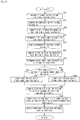
- the optical head translation mechanism 132 is moved in the Z direction, thereby displacing the optical head 104. Then, the S_signal voltage VS and the A+B_signal voltage V(A+B) corresponding to a change in the distance Z, in the vicinity of the in-focus position PFJ, between the objective lens 114 and the measurement workpiece 102 are measured in regular increments of the distance Z between the objective lens 114 and the measurement workpiece 102 ( Fig. 2(A) and step S2 of Fig. 3 ). Then, the measurement results are sequentially stored in the S_signal & A+B_signal & position data storage unit 144.
- the S_signal voltage VS, the A+B_signal voltage V(A+B), and the position data are read into the computation & control unit 146.
- the A+B_signal voltages V(A+B) at the distance Z which give the maximum voltage and the minimum voltage of the S_signal voltage VS are defined as a first voltage R and a second voltage W, respectively. That is, a maximum position P of the S_signal voltage VS is calculated, and the A+B_signal voltage V(A+B) corresponding to the maximum position P is determined as the first voltage R ( Fig. 2(B) and step S4 of Fig. 3 ).
- a minimum position U of the S_signal voltage VS is calculated and the A+B_signal voltage V(A+B) corresponding to the minimum position U is determined as the second voltage W ( Fig. 2(C) and step S6 of Fig. 3 ).
- the higher one of the first voltage R and the second voltage W is defined as the S_signal validity determination voltage VSV, which is a threshold voltage for determining the in-focus determination voltage VFJ to be valid. That is, the first voltage R and the second voltage W are compared with each other (step S8 of Fig. 3 ). After that, if the first voltage R is equal to or greater than the second voltage W, then the first voltage R is employed as the S_signal validity determination voltage VSV ( Fig. 2(C) , step S10 of Fig. 3 , the present embodiment being the case). In contrast, if the first voltage R is less than the second voltage W, then the second voltage W is employed as the S_signal validity determination voltage VSV (step S12 of Fig. 3 ).
- the resulting S_signal validity determination voltage VSV is stored in the S_signal validity determination voltage storage unit 148 (step S14 of Fig. 3 ).
- the position of the S_signal voltage VS given by the in-focus determination voltage VFJ is employed as the focal distance of the objective lens 114 ( Fig. 2(D) ).
- the A+B_signal voltage V(A+B) specified by either the maximum position P or the minimum position U of the S_signal voltage VS is employed as the S_signal validity determination voltage VSV. It is thus possible to prevent the in-focus position determinable region EAV specified by the S_signal validity determination voltage VSV from extending out of the maximum position P and the minimum position U of the S_signal voltage VS and determine the in-focus position determinable region EAV with reliability.
- the present embodiment can be employed for various types of measurement workpieces 102 while enabling easy-to-handle stable autofocus control.
- the processing unit 108 includes the external-communication unit 150 connected to the computation & control unit 146, and the host controller 152 capable of communicating with the external-communication unit 150, and the host controller 152 is connected with the input and output unit 154.
- the present invention is not limited thereto. It is also acceptable that the external-communication unit 150 and the host controller 152 are eliminated, with the input and output unit 154 connected directly to the computation & control unit.
- the computation & control unit 146 defines the S_signal validity determination voltage VSV and the in-focus determination voltage VFJ that gives the focal distance of the objective lens 114.
- the computation & control unit 146 may be simply configured to control the exchange of data between the S_signal & A+B_signal & position data storage unit 144, the S_signal validity determination voltage storage unit 148, and the external-communication unit 150, allowing the aforementioned computations to be performed by the host controller 152.
- FIG. 4 a description will be made to the configuration of an autofocus mechanism according to a second embodiment with attention concentrated on the points that are different from those of the first embodiment.
- a processing unit 208 of the present embodiment includes an A_signal voltage converter unit 234, a B_signal voltage converter unit 236, an A+B_signal voltage converter unit 238, an S_signal voltage converter unit 240, an S_signal & A+B_signal voltage detector unit 242, an S_signal & A+B_signal & position data storage unit 244, a computation & control unit 246 (the first lower limit voltage computing means + the second lower limit voltage computing means + the lower limit voltage computing means + the upper limit voltage computing means), an S_signal validity determination voltage storage unit 248 (the storage unit), an external-communication unit 250 (the communication means), a host controller 252, and an input and output unit 254 (the output means).
- the A_ and B_signal voltage converter units 234 and 236 convert signals output from the first and second photodiodes 124 and 128 into voltages, i.e., the A_ and B_signal voltages, respectively.
- the A_ and B_signal voltages are converted by the A+B_signal voltage converter unit 238 into the A+B_signal voltage V(A+B) in accordance with Equation (1) and converted by the S_signal voltage converter unit 240 into the S_signal voltage VS in accordance with Equation (2).
- the S_signal & A+B_signal voltage detector unit 242 measures the S_signal voltage VS and the A+B_signal voltage V(A+B) corresponding to a change in the distance Z between the objective lens 114 and the measurement workpiece 102, thereby converting each of the voltages VS and V(A+B) into data.
- the S_signal & A+B_signal & position data storage unit 244 stores, in combination, the S_signal voltage VS and the A+B_signal voltage V(A+B) having been converted into data, and the position data of the distance Z output from the position detector unit 130.
- the computation & control unit 246 calculates an upper limit voltage Vmax and a lower limit voltage Vmin of a settable range of the S_signal validity determination voltage VSV from the aforementioned combination of data.
- the S_signal validity determination voltage VSV determines a valid region of the in-focus determination voltage VFJ at the distance Z, thus serving as the threshold voltage for determining, as valid, the in-focus determination voltage VFJ at the distance Z at which a voltage obtained by subtracting itself from the A+B_signal voltage V(A+B) is equal to or greater than zero (the in-focus determination voltage VFJ is obtained when the distance Z is equal to the focal distance of the objective lens 114).
- the external-communication unit 250 is connected to the computation & control unit 246 and capable of communicating with the host controller 252 (either by radio or by wire). That is, the external-communication unit 250 is configured to inform the host controller 252 of the upper limit voltage Vmax and the lower limit voltage Vmin.
- the host controller 252 is connected with the input and output unit 254.
- the input and output unit 254 is made up of, for example, a keyboard, a loudspeaker, and a monitor, so that the upper limit voltage Vmax and the lower limit voltage Vmin are displayed (output) on the monitor as the upper limit value and the lower limit value of a settable range of the S_signal validity determination voltage VSV.
- the operator enters the S_signal validity determination voltage VSV on the keyboard.
- the entered S_signal validity determination voltage VSV is transferred from the host controller 252 to the external-communication unit 250.
- the S_signal validity determination voltage VSV is stored in the S_signal validity determination voltage storage unit 248 connected to the computation & control unit 246.
- the stored S_signal validity determination voltage VSV is used for autofocus control. Note that in the processing unit 208, the host controller 252 and the input and output unit 254 are separated from the other components, thereby allowing the host controller 252 and the input and output unit 254 to be shared with other autofocus mechanisms.
- the optical head translation mechanism 132 is moved in the Z direction, thereby displacing the optical head 104. Then, the S_signal voltage VS and the A+B_signal voltage V(A+B) corresponding to a change in the distance Z, in the vicinity of the in-focus position PFJ, between the objective lens 114 and the measurement workpiece 102 are measured in regular increments of the distance Z between the objective lens 114 and the measurement workpiece 102 ( Fig. 5(A) and step S22 of Fig. 6 ). Then, the measurement results are sequentially stored in the S_signal & A+B_signal & position data storage unit 244.
- the S_signal voltage VS, the A+B_signal voltage V(A+B), and the position data are read into the computation & control unit 246.
- a maximum position P indicative of the maximum voltage of the S_signal voltage VS is calculated (step S24 of Fig. 6 ).
- calculated is a first in-focus determination position Q on the S_signal voltage VS which is located so as to decrease the distance Z between the objective lens 114 and the measurement workpiece 102 from the maximum position P (leftward in the direction of Z in Fig. 5(B) ) (step S26 of Fig. 6 ).
- the first in-focus determination position Q is the position at which the sum of the in-focus determination voltage VFJ and an allowable voltage D (a first in-focus determination voltage VFM1) is equal to the S_signal voltage VS.
- the in-focus determination voltage VFJ is obtained when the distance Z is equal to the focal distance of the objective lens 114.
- the allowable voltage D is defined by taking into account electrical noise in the autofocus mechanism 100 and measurement errors caused by vibrations of mechanical parts, and set to be less than the voltage obtained by subtracting the in-focus determination voltage VFJ from the maximum voltage of the S_signal voltage VS (Taking a specific example, the optical head 104 is stopped at the in-focus position PFJ and the S_signal voltage VS is measured several times.
- the standard deviation (3 ⁇ ) is determined, and half that value can be employed as the allowable voltage D). Then, the A+B_signal voltage V(A+B) at the same distance Z as the first in-focus determination position Q is defined as a first lower limit voltage R' ( Fig. 5(B) and step S28 of Fig. 6 ).
- the minimum position U indicative of the minimum voltage of the S_signal voltage VS is calculated (step S30 of Fig. 6 ). Then, calculated is a second in-focus determination position V on the S_signal voltage VS which is located so as to increase the distance Z between the objective lens 114 and the measurement workpiece 102 from the minimum position U (rightward in the direction of Z in Fig. 5(C) ) (step S32 of Fig. 6 ).
- the second in-focus determination position V is the position at which the difference between the in-focus determination voltage VFJ and the allowable voltage D (a second in-focus determination voltage VFM2) is equal to the S_signal voltage VS.
- the A+B_signal voltage V(A+B) at the same distance Z as the second in-focus determination position V is defined as a second lower limit voltage W' ( Fig. 5(C) , step S34 of Fig. 6 ).
- the higher one of the first and second lower limit voltages R' and W' is defined as the lower limit voltage Vmin of a settable range of the S_signal validity determination voltage VSV. That is, the first lower limit voltage R' and the second lower limit voltage W' are compared (step S36 of Fig. 6 ). After that, if the first lower limit voltage R' is equal to or greater than the second lower limit voltage W', then the first lower limit voltage R' is employed as the lower limit voltage Vmin (step S38 of Fig. 6 , the present embodiment being the case). In contrast, if the first lower limit voltage R' is less than the second lower limit voltage W', then the second lower limit voltage W' is employed as the lower limit voltage Vmin (step S40 of Fig. 6 ).
- the A+B_signal voltage V(A+B) at the same distance Z as the focusing determination position S is defined as the upper limit voltage Vmax ( Fig. 5(D) and step S44 of Fig. 6 ).
- the computation & control unit 246 transmits the upper limit voltage Vmax and the lower limit voltage Vmin to the host controller 252 through the external-communication unit 250.
- the host controller 252 outputs (provides a display notice of) the upper limit voltage Vmax and the lower limit voltage Vmin on the input and output unit 254 as the upper limit value and the lower limit value of a settable range of the S_signal validity determination voltage VSV, i.e., a threshold voltage which determines, as valid, the in-focus determination voltage VFJ at the distance Z at which a voltage obtained by subtracting itself from the A+B_signal voltage V(A+B) is equal to or greater than zero (step S46 of Fig. 6 ).
- each portion has a different A+B_signal voltage V(A+B) for the distance Z between the objective lens and the measurement workpiece.
- V(A+B) the A+B_signal voltage for the distance Z between the objective lens and the measurement workpiece.
- each portion had a different optimum S_signal validity determination voltage VSV, thereby causing the S_signal validity determination voltage VSV to be set with difficulty.
- the upper limit value and the lower limit value of a settable range of the S_signal validity determination voltage VSV for autofocus control is notified.
- the present embodiment is particularly useful for the measurement workpiece 102, like a patterned IC, which has a plurality of portions of different reflectivities.
- the autofocus mechanism 100 of the present embodiment is applicable to optical microscopes, FPD (flat panel display) testing/repair apparatus, LCD testing/repair apparatus, IC testing/repair apparatus, and non-contact displacement measuring devices.
- the S_signal validity determination voltage VSV can be entered into the input and output unit 254, and the processing unit 208 includes the S_signal validity determination voltage storage unit 248 which stores the S_signal validity determination voltage VSV. This makes it possible to provide autofocus control with stability and high reproducibility using the S_signal validity determination voltage VSV defined on the basis of a settable range.
- the processing unit 208 includes the external-communication unit 250 connected to the computation & control unit 246, and the host controller 252 capable of communicating with the external-communication unit 250, and the host controller 252 is connected with the input and output unit 254.
- the host controller 252 and the input and output unit 254 can be used in common for a plurality of autofocus mechanisms. That is, the autofocus mechanism 100 can be provided at lower costs.
- the present embodiment can be employed for various types of measurement workpieces 102 while enabling easy-to-handle stable autofocus control.
- the processing unit 208 includes the S_signal validity determination voltage storage unit 248 which stores the S_signal validity determination voltage VSV.
- the present invention is not limited thereto.
- an adjustment mechanism such as an optical head may be included, in the case of which it does not serve as an input and output unit but serves only to display and the adjustment mechanism enables the optical head to be adjusted within a settable range of a defined S_signal validity determination voltage VSV.
- the S_signal validity determination voltage storage unit may be eliminated, so that the S_signal validity determination voltage VSV is entered each time autofocus control is provided.
- the processing unit 208 includes the external-communication unit 250 connected to the computation & control unit 246, and the host controller 252 capable of communicating with the external-communication unit 250, and the host controller 252 is connected with the input and output unit 254.
- the present invention is not limited thereto.
- the external-communication unit and the host controller may be eliminated, so that the input and output unit 254 is directly connected to the computation & control unit 246.
- the computation & control unit 246 defines the upper limit voltage Vmax and the lower limit voltage Vmin.
- the computation & control unit 246 may control only the exchange of data between the S_signal & A+B_signal & position data storage unit 244, the S_signal validity determination voltage storage unit 248, and the external-communication unit 250, while the host controller 252 performs computations to determine the upper limit voltage Vmax and the lower limit voltage Vmin.
- the present invention relates particularly to an autofocus mechanism which employs a laser beam, and widely applicable to optical microscopes, FPD (flat panel display) testing/repair apparatus, LCD testing/repair apparatus, IC testing/repair apparatus, and non-contact displacement measuring devices.
Landscapes
- Physics & Mathematics (AREA)
- Optics & Photonics (AREA)
- Engineering & Computer Science (AREA)
- Chemical & Material Sciences (AREA)
- Analytical Chemistry (AREA)
- General Physics & Mathematics (AREA)
- Microelectronics & Electronic Packaging (AREA)
- General Engineering & Computer Science (AREA)
- Length Measuring Devices By Optical Means (AREA)
- Microscoopes, Condenser (AREA)
- Automatic Focus Adjustment (AREA)
- Measurement Of Optical Distance (AREA)
Claims (6)
- Autofokusmechanismus, umfassend:eine Objektivlinse (114), die einen Laserstrahl sammelt, um ein Messwerkstück (102) damit zu bestrahlen;einen Strahlteiler (120), der Licht teilt, das von dem Messwerkstück (102) durch die Objektivlinse (114) reflektiert wird;ein erstes Lichtmengenbegrenzungselement (122), das vor einer Fokusposition eines geteilten Strahls des reflektierten Lichts angeordnet ist;ein erstes lichtempfangendes Element (124), das den reflektierten Strahl empfängt, der durch das erste Lichtmengenbegrenzungselement (122) durchgegangen ist;ein zweites Lichtmengenbegrenzungselement (126), das hinter einer Fokusposition des anderen geteilten Strahls des reflektierten Lichts angeordnet ist;ein zweites lichtempfangendes Element (128), das den reflektierten Strahl empfängt, der durch das zweite Lichtmengenbegrenzungselement (126) durchgegangen ist; undeine Verarbeitungseinheit (108), die Signale, die von dem ersten und dem zweiten lichtempfangenden Element (124, 128) ausgegeben wurden, in eine A_Signalspannung bzw. eine B_Signalspannung umwandelt, um eine A+B_Signalspannung und eine S_Signalspannung zu bestimmen, die durch die nachstehenden Gleichungen (1) und (2) ausgedrückt werden,

 dadurch gekennzeichnet, dass die Verarbeitungseinheit (108) umfasst:ein Mittel zum Berechnen der ersten und der zweiten Spannung (146), das, als eine erste Spannung und eine zweite Spannung, A+B_Signalspannungen an Abständen zwischen der Objektivlinse (114) und dem Messwerkstück (102) definiert, wobei die erste Spannung und die zweite Spannung die Höchstspannung bzw. die Mindestspannung der S_Signalspannung anzeigt;ein S_Signalgültigkeitsbestimmungspannungsberechnungsmittel (146), das eine höhere der ersten Spannung und der zweiten Spannung als eine S_Signalgültigkeitsbestimmungsspannung definiert, die als eine Schwellenspannung dient, die eine In-Fokusbestimmungsspannung als gültig bestimmt, wobei die In-Fokusbestimmungsspannung gleich der S_Signalspannung ist, die erhalten wird, wenn der Abstand gleich einer Brennweite der Objektivlinse (114) ist; undein Brennweitenberechnungsmittel (146), das als die Brennweite der Objektivlinse (114) einen Abstand definiert, bei dem die S_Signalspannung die In-Fokusbestimmungsspannung annimmt, wobei der Abstand, der durch die A+B_Signalspannung gegeben wird, gleich oder größer ist als die S_Signalgültigkeitsbestimmungsspannung.
 - Autofokusmechanismus nach Anspruch 1, umfassend eine Speichereinheit (148), die die S_Signalgültigkeitsbestimmungsspannung speichert.
- Autofokusmechanismus nach Anspruch 1 oder 2, wobei die Verarbeitungseinheit (108) ein Kommunikationsmittel (150) umfasst, das mit dem S_Signalgültigkeitsbestimmungsspannungsberechnungsmittel (146) verbunden ist, und eine Host-Steuerung (152), die fähig ist, mit dem Kommunikationsmittel (150) zu kommunizieren.
- Autofokusmechanismus, umfassend:eine Objektivlinse (114), die einen Laserstrahl sammelt, um ein Messwerkstück (102) damit zu bestrahlen;einen Strahlteiler (120), der Licht teilt, das von dem Messwerkstück (102) durch die Objektivlinse (114) reflektiert wird;ein erstes Lichtmengenbegrenzungselement (122), das vor einer Fokusposition eines geteilten Strahls des reflektierten Lichts angeordnet ist;ein erstes lichtempfangendes Element (124), das den reflektierten Strahl empfängt, der durch das erste Lichtmengenbegrenzungselement (122) durchgegangen ist;ein zweites Lichtmengenbegrenzungselement (126), das hinter einer Fokusposition des anderen geteilten Strahls des reflektierten Lichts angeordnet ist;ein zweites lichtempfangendes Element (128), das den reflektierten Strahl empfängt, der durch das zweite Lichtmengenbegrenzungselement (126) durchgegangen ist; undeine Verarbeitungseinheit (208), die Signale, die von dem ersten und dem zweiten lichtempfangenden Element (124, 128) ausgegeben wurden, in eine A_Signalspannung bzw. eine B_Signalspannung umwandelt, um eine A+B_Signalspannung und eine S_Signalspannung zu bestimmen, die durch die nachstehenden Gleichungen (1) und (2) ausgedrückt werden,

 dadurch gekennzeichnet, dass die Verarbeitungseinheit (208) umfasst:ein erstes Untergrenzenspannungsberechnungsmittel (246), das eine erste Untergrenzenspannung definiert, um einen Abstand zwischen der Objektivlinse (114) und dem Messwerkstück (102) von einer Höchstposition, die eine Höchstspannung der S_Signalspannung anzeigt, zu reduzieren, wobei die erste Untergrenzenspannung als die A+B_Signalspannung in einem Abstand definiert ist, in dem die Summe einer In-Fokusbestimmungsspannung und einer zulässigen Spannung die S_Signalspannung ist, wobei die In-Fokusbestimmungsspannung die S_Signalspannung ist, die erhalten wird, wenn der Abstand gleich der Brennweite der Objektivlinse (114) ist, wobei die zulässige Spannung eine Spannung ist, die so festgelegt ist, dass sie geringer ist als eine Spannung, die durch Subtrahieren der In-Fokusbestimmungsspannung von der Höchstspannung der S_Signalspannung erhalten wird;ein zweites Untergrenzenspannungsberechnungsmittel (246), das eine zweite Untergrenzenspannung definiert, um den Abstand von einer Mindestposition, die eine Mindestspannung der S_Signalspannung anzeigt, zu erhöhen, wobei die zweite Untergrenzenspannung als die A+B_Signalspannung an dem Abstand definiert wird, an dem eine Differenz zwischen der In-Fokusbestimmungsspannung und der zulässigen Spannung gleich der S_Signalspannung ist;ein Untergrenzenspannungsberechnungsmittel (246), das eine höhere der ersten und der zweiten Untergrenzenspannung als eine Untergrenzenspannung definiert;ein Obergrenzenspannungsberechnungsmittel (246), das als eine Obergrenzenspannung die A+B_Signalspannung an dem Abstand definiert, der die In-Fokusbestimmungsspannung zwischen der Höchstposition und der Mindestposition der S_Signalspannung ergibt; undein Ausgabemittel (254), das die Obergrenzenspannung und die Untergrenzenspannung als einen Obergrenzenwert und einen Untergrenzenwert eines festlegbaren Bereichs einer S_Signalgültigkeitsbestimmungsspannung ausgibt, wobei die S_Signalgültigkeitsbestimmungsspannung eine Schwellenspannung ist, um die In-Fokusbestimmungsspannung an dem Abstand als gültig zu bestimmen, an dem eine Spannung, die durch Subtrahieren derselben von der A+B_Signalspannung erhalten wird, gleich oder größer als null ist.
 - Autofokusmechanismus nach Anspruch 4, wobei das Ausgabemittel als eine Eingabe- und Ausgabeeinheit (254) dient, in die die S_Signalgültigkeitsbestimmungsspannung eingegeben werden kann, und die Verarbeitungseinheit (208) eine Speichereinheit (248) umfasst, die die S_Signalgültigkeitsbestimmungsspannung speichert.
- Autofokusmechanismus nach Anspruch 4 oder 5, wobei die Verarbeitungseinheit (208) ein Kommunikationsmittel (250) umfasst, das mit dem Untergrenzenspannungsberechnungsmittel (246) und dem Obergrenzenspannungsberechnungsmittel (246) und einer Host-Steuerung (252), die fähig ist, mit dem Kommunikationsmittel (250) zu kommunizieren, verbunden ist, und die Host-Steuerung (252) mit dem Ausgabemittel (254) verbunden ist.
Applications Claiming Priority (2)
| Application Number | Priority Date | Filing Date | Title |
|---|---|---|---|
| JP2012094297A JP5864346B2 (ja) | 2012-04-17 | 2012-04-17 | オートフォーカス機構 |
| JP2012094298A JP5864347B2 (ja) | 2012-04-17 | 2012-04-17 | オートフォーカス機構 |
Publications (2)
| Publication Number | Publication Date |
|---|---|
| EP2653902A1 EP2653902A1 (de) | 2013-10-23 |
| EP2653902B1 true EP2653902B1 (de) | 2019-01-02 |
Family
ID=48190093
Family Applications (1)
| Application Number | Title | Priority Date | Filing Date |
|---|---|---|---|
| EP13163942.9A Not-in-force EP2653902B1 (de) | 2012-04-17 | 2013-04-16 | Autofokusmechanismus |
Country Status (3)
| Country | Link |
|---|---|
| US (1) | US9031399B2 (de) |
| EP (1) | EP2653902B1 (de) |
| CN (1) | CN103376531B (de) |
Families Citing this family (8)
| Publication number | Priority date | Publication date | Assignee | Title |
|---|---|---|---|---|
| US20150205088A1 (en) * | 2014-01-23 | 2015-07-23 | U&U Engineering Inc. | Bevel-axial auto-focusing microscopic system and method thereof |
| EP2977720B1 (de) | 2014-07-25 | 2019-06-05 | Mitutoyo Corporation | Verfahren zur Messung einer hochgenauen Höhenkarte einer Testoberfläche |
| WO2016022359A1 (en) * | 2014-08-06 | 2016-02-11 | Cellomics, Inc. | Image-based laser autofocus system |
| CN106772923B (zh) * | 2015-11-24 | 2021-01-01 | 睿励科学仪器(上海)有限公司 | 基于倾斜狭缝的自动对焦方法和系统 |
| CN105657278A (zh) * | 2016-02-29 | 2016-06-08 | 广东欧珀移动通信有限公司 | 控制方法、控制装置及电子装置 |
| JP2018017970A (ja) | 2016-07-29 | 2018-02-01 | オリンパス株式会社 | 光シート顕微鏡、及び、光シート顕微鏡の制御方法 |
| CN109283672B (zh) * | 2017-07-19 | 2021-05-28 | 深圳华大智造科技股份有限公司 | 自动对焦装置 |
| CN120266030A (zh) * | 2023-03-08 | 2025-07-04 | 深圳华大生命科学研究院 | 对焦方法和系统 |
Family Cites Families (10)
| Publication number | Priority date | Publication date | Assignee | Title |
|---|---|---|---|---|
| JPS6040603B2 (ja) * | 1977-12-22 | 1985-09-11 | 旭光学工業株式会社 | カメラの焦点検出装置 |
| JPS5576312A (en) * | 1978-12-04 | 1980-06-09 | Canon Inc | Focus detecting system of image |
| JPH0843717A (ja) | 1994-08-02 | 1996-02-16 | Olympus Optical Co Ltd | 焦点検出装置 |
| JP3628741B2 (ja) | 1995-02-13 | 2005-03-16 | オリンパス株式会社 | オートフォーカス顕微鏡 |
| JPH11337812A (ja) | 1998-05-21 | 1999-12-10 | Olympus Optical Co Ltd | オートフォーカス装置 |
| JP2000162506A (ja) | 1998-11-30 | 2000-06-16 | Tokyo Seimitsu Co Ltd | 共焦点顕微鏡 |
| JP4519987B2 (ja) | 2000-04-13 | 2010-08-04 | オリンパス株式会社 | 焦点検出装置 |
| US7187630B2 (en) * | 2001-06-11 | 2007-03-06 | Mitutoyo Corporation | Focusing servo device and focusing servo method |
| EP1821128B1 (de) * | 2004-11-16 | 2011-03-16 | Citizen Holdings Co., Ltd. | Automatisches fokussierungsgerät |
| JP4407564B2 (ja) * | 2005-04-15 | 2010-02-03 | ソニー株式会社 | オートフォーカス装置とオートフォーカス方法およびプログラム |
-
2013
- 2013-03-15 US US13/835,098 patent/US9031399B2/en active Active
- 2013-04-16 EP EP13163942.9A patent/EP2653902B1/de not_active Not-in-force
- 2013-04-17 CN CN201310132805.7A patent/CN103376531B/zh not_active Expired - Fee Related
Non-Patent Citations (1)
| Title |
|---|
| None * |
Also Published As
| Publication number | Publication date |
|---|---|
| EP2653902A1 (de) | 2013-10-23 |
| US20130271995A1 (en) | 2013-10-17 |
| CN103376531A (zh) | 2013-10-30 |
| CN103376531B (zh) | 2017-04-26 |
| US9031399B2 (en) | 2015-05-12 |
Similar Documents
| Publication | Publication Date | Title |
|---|---|---|
| EP2653902B1 (de) | Autofokusmechanismus | |
| US20140027421A1 (en) | Method of Determining a Focal Point or Beam Profile of a Laser Beam in a Working Field | |
| US11740356B2 (en) | Dual-optical displacement sensor alignment using knife edges | |
| SG173479A1 (en) | Method for noncontact measurement of surface shape and device thereof | |
| US10473783B2 (en) | Laser processing device and laser processing system | |
| JP2014006134A (ja) | 光学測定装置 | |
| CN108375349A (zh) | 倾斜测定装置 | |
| JP4996043B2 (ja) | 光波距離測定方法及び光波距離測定装置 | |
| US8289525B2 (en) | Optical surface measuring apparatus and method | |
| JP3294985B2 (ja) | 表面の曲率測定装置 | |
| US10260988B2 (en) | Non-contact measurement device for radius of curvature and thickness of lens and measurement method thereof | |
| US6621559B1 (en) | Electronic leveling apparatus and method of controlling focusing operation of the electronic leveling apparatus | |
| KR102872440B1 (ko) | 촬상 장치 | |
| US9255788B1 (en) | Measuring method for linear stage | |
| JP5864347B2 (ja) | オートフォーカス機構 | |
| JP5864346B2 (ja) | オートフォーカス機構 | |
| JPH10253892A (ja) | 位相干渉顕微鏡 | |
| TWI507663B (zh) | 線性平台之量測裝置及其量測方法 | |
| CN101320218B (zh) | 三扫描式硅片调焦调平测量装置、系统以及方法 | |
| JPS61223604A (ja) | ギヤツプ測定装置 | |
| JP2008227164A (ja) | レーザ加工装置およびレーザ加工方法 | |
| GB2468177A (en) | Optical surface measuring apparatus and method | |
| JP2019163946A (ja) | 非接触表面形状測定装置 | |
| KR20190107793A (ko) | 압연재 폭 측정장치 | |
| KR200300101Y1 (ko) | 레이저 중심도 및 경사도 동시측정 장치 |
Legal Events
| Date | Code | Title | Description |
|---|---|---|---|
| PUAI | Public reference made under article 153(3) epc to a published international application that has entered the european phase |
Free format text: ORIGINAL CODE: 0009012 |
|
| AK | Designated contracting states |
Kind code of ref document: A1 Designated state(s): AL AT BE BG CH CY CZ DE DK EE ES FI FR GB GR HR HU IE IS IT LI LT LU LV MC MK MT NL NO PL PT RO RS SE SI SK SM TR |
|
| AX | Request for extension of the european patent |
Extension state: BA ME |
|
| 17P | Request for examination filed |
Effective date: 20140321 |
|
| RBV | Designated contracting states (corrected) |
Designated state(s): AL AT BE BG CH CY CZ DE DK EE ES FI FR GB GR HR HU IE IS IT LI LT LU LV MC MK MT NL NO PL PT RO RS SE SI SK SM TR |
|
| GRAP | Despatch of communication of intention to grant a patent |
Free format text: ORIGINAL CODE: EPIDOSNIGR1 |
|
| RIC1 | Information provided on ipc code assigned before grant |
Ipc: F21K 9/65 20160101ALI20180528BHEP Ipc: G02B 21/24 20060101AFI20180528BHEP |
|
| STAA | Information on the status of an ep patent application or granted ep patent |
Free format text: STATUS: GRANT OF PATENT IS INTENDED |
|
| INTG | Intention to grant announced |
Effective date: 20180705 |
|
| GRAS | Grant fee paid |
Free format text: ORIGINAL CODE: EPIDOSNIGR3 |
|
| GRAA | (expected) grant |
Free format text: ORIGINAL CODE: 0009210 |
|
| STAA | Information on the status of an ep patent application or granted ep patent |
Free format text: STATUS: THE PATENT HAS BEEN GRANTED |
|
| AK | Designated contracting states |
Kind code of ref document: B1 Designated state(s): AL AT BE BG CH CY CZ DE DK EE ES FI FR GB GR HR HU IE IS IT LI LT LU LV MC MK MT NL NO PL PT RO RS SE SI SK SM TR |
|
| RAP1 | Party data changed (applicant data changed or rights of an application transferred) |
Owner name: MITUTOYO CORPORATION |
|
| REG | Reference to a national code |
Ref country code: GB Ref legal event code: FG4D |
|
| REG | Reference to a national code |
Ref country code: CH Ref legal event code: EP Ref country code: AT Ref legal event code: REF Ref document number: 1085128 Country of ref document: AT Kind code of ref document: T Effective date: 20190115 |
|
| REG | Reference to a national code |
Ref country code: IE Ref legal event code: FG4D |
|
| REG | Reference to a national code |
Ref country code: DE Ref legal event code: R096 Ref document number: 602013049061 Country of ref document: DE |
|
| REG | Reference to a national code |
Ref country code: CH Ref legal event code: PK Free format text: BERICHTIGUNGEN |
|
| RIC2 | Information provided on ipc code assigned after grant |
Ipc: G02B 21/24 20060101AFI20180528BHEP Ipc: F21K 9/65 20160101ALI20180528BHEP |
|
| REG | Reference to a national code |
Ref country code: NL Ref legal event code: MP Effective date: 20190102 |
|
| REG | Reference to a national code |
Ref country code: LT Ref legal event code: MG4D |
|
| REG | Reference to a national code |
Ref country code: AT Ref legal event code: MK05 Ref document number: 1085128 Country of ref document: AT Kind code of ref document: T Effective date: 20190102 |
|
| PG25 | Lapsed in a contracting state [announced via postgrant information from national office to epo] |
Ref country code: NL Free format text: LAPSE BECAUSE OF FAILURE TO SUBMIT A TRANSLATION OF THE DESCRIPTION OR TO PAY THE FEE WITHIN THE PRESCRIBED TIME-LIMIT Effective date: 20190102 |
|
| PG25 | Lapsed in a contracting state [announced via postgrant information from national office to epo] |
Ref country code: ES Free format text: LAPSE BECAUSE OF FAILURE TO SUBMIT A TRANSLATION OF THE DESCRIPTION OR TO PAY THE FEE WITHIN THE PRESCRIBED TIME-LIMIT Effective date: 20190102 Ref country code: LT Free format text: LAPSE BECAUSE OF FAILURE TO SUBMIT A TRANSLATION OF THE DESCRIPTION OR TO PAY THE FEE WITHIN THE PRESCRIBED TIME-LIMIT Effective date: 20190102 Ref country code: PL Free format text: LAPSE BECAUSE OF FAILURE TO SUBMIT A TRANSLATION OF THE DESCRIPTION OR TO PAY THE FEE WITHIN THE PRESCRIBED TIME-LIMIT Effective date: 20190102 Ref country code: FI Free format text: LAPSE BECAUSE OF FAILURE TO SUBMIT A TRANSLATION OF THE DESCRIPTION OR TO PAY THE FEE WITHIN THE PRESCRIBED TIME-LIMIT Effective date: 20190102 Ref country code: NO Free format text: LAPSE BECAUSE OF FAILURE TO SUBMIT A TRANSLATION OF THE DESCRIPTION OR TO PAY THE FEE WITHIN THE PRESCRIBED TIME-LIMIT Effective date: 20190402 Ref country code: PT Free format text: LAPSE BECAUSE OF FAILURE TO SUBMIT A TRANSLATION OF THE DESCRIPTION OR TO PAY THE FEE WITHIN THE PRESCRIBED TIME-LIMIT Effective date: 20190502 Ref country code: SE Free format text: LAPSE BECAUSE OF FAILURE TO SUBMIT A TRANSLATION OF THE DESCRIPTION OR TO PAY THE FEE WITHIN THE PRESCRIBED TIME-LIMIT Effective date: 20190102 |
|
| PG25 | Lapsed in a contracting state [announced via postgrant information from national office to epo] |
Ref country code: GR Free format text: LAPSE BECAUSE OF FAILURE TO SUBMIT A TRANSLATION OF THE DESCRIPTION OR TO PAY THE FEE WITHIN THE PRESCRIBED TIME-LIMIT Effective date: 20190403 Ref country code: RS Free format text: LAPSE BECAUSE OF FAILURE TO SUBMIT A TRANSLATION OF THE DESCRIPTION OR TO PAY THE FEE WITHIN THE PRESCRIBED TIME-LIMIT Effective date: 20190102 Ref country code: HR Free format text: LAPSE BECAUSE OF FAILURE TO SUBMIT A TRANSLATION OF THE DESCRIPTION OR TO PAY THE FEE WITHIN THE PRESCRIBED TIME-LIMIT Effective date: 20190102 Ref country code: LV Free format text: LAPSE BECAUSE OF FAILURE TO SUBMIT A TRANSLATION OF THE DESCRIPTION OR TO PAY THE FEE WITHIN THE PRESCRIBED TIME-LIMIT Effective date: 20190102 Ref country code: BG Free format text: LAPSE BECAUSE OF FAILURE TO SUBMIT A TRANSLATION OF THE DESCRIPTION OR TO PAY THE FEE WITHIN THE PRESCRIBED TIME-LIMIT Effective date: 20190402 Ref country code: IS Free format text: LAPSE BECAUSE OF FAILURE TO SUBMIT A TRANSLATION OF THE DESCRIPTION OR TO PAY THE FEE WITHIN THE PRESCRIBED TIME-LIMIT Effective date: 20190502 |
|
| REG | Reference to a national code |
Ref country code: DE Ref legal event code: R097 Ref document number: 602013049061 Country of ref document: DE |
|
| PG25 | Lapsed in a contracting state [announced via postgrant information from national office to epo] |
Ref country code: SK Free format text: LAPSE BECAUSE OF FAILURE TO SUBMIT A TRANSLATION OF THE DESCRIPTION OR TO PAY THE FEE WITHIN THE PRESCRIBED TIME-LIMIT Effective date: 20190102 Ref country code: RO Free format text: LAPSE BECAUSE OF FAILURE TO SUBMIT A TRANSLATION OF THE DESCRIPTION OR TO PAY THE FEE WITHIN THE PRESCRIBED TIME-LIMIT Effective date: 20190102 Ref country code: CZ Free format text: LAPSE BECAUSE OF FAILURE TO SUBMIT A TRANSLATION OF THE DESCRIPTION OR TO PAY THE FEE WITHIN THE PRESCRIBED TIME-LIMIT Effective date: 20190102 Ref country code: AL Free format text: LAPSE BECAUSE OF FAILURE TO SUBMIT A TRANSLATION OF THE DESCRIPTION OR TO PAY THE FEE WITHIN THE PRESCRIBED TIME-LIMIT Effective date: 20190102 Ref country code: DK Free format text: LAPSE BECAUSE OF FAILURE TO SUBMIT A TRANSLATION OF THE DESCRIPTION OR TO PAY THE FEE WITHIN THE PRESCRIBED TIME-LIMIT Effective date: 20190102 Ref country code: AT Free format text: LAPSE BECAUSE OF FAILURE TO SUBMIT A TRANSLATION OF THE DESCRIPTION OR TO PAY THE FEE WITHIN THE PRESCRIBED TIME-LIMIT Effective date: 20190102 Ref country code: EE Free format text: LAPSE BECAUSE OF FAILURE TO SUBMIT A TRANSLATION OF THE DESCRIPTION OR TO PAY THE FEE WITHIN THE PRESCRIBED TIME-LIMIT Effective date: 20190102 Ref country code: IT Free format text: LAPSE BECAUSE OF FAILURE TO SUBMIT A TRANSLATION OF THE DESCRIPTION OR TO PAY THE FEE WITHIN THE PRESCRIBED TIME-LIMIT Effective date: 20190102 |
|
| PLBE | No opposition filed within time limit |
Free format text: ORIGINAL CODE: 0009261 |
|
| STAA | Information on the status of an ep patent application or granted ep patent |
Free format text: STATUS: NO OPPOSITION FILED WITHIN TIME LIMIT |
|
| PG25 | Lapsed in a contracting state [announced via postgrant information from national office to epo] |
Ref country code: SM Free format text: LAPSE BECAUSE OF FAILURE TO SUBMIT A TRANSLATION OF THE DESCRIPTION OR TO PAY THE FEE WITHIN THE PRESCRIBED TIME-LIMIT Effective date: 20190102 |
|
| REG | Reference to a national code |
Ref country code: CH Ref legal event code: PL |
|
| 26N | No opposition filed |
Effective date: 20191003 |
|
| REG | Reference to a national code |
Ref country code: BE Ref legal event code: MM Effective date: 20190430 |
|
| GBPC | Gb: european patent ceased through non-payment of renewal fee |
Effective date: 20190416 |
|
| PG25 | Lapsed in a contracting state [announced via postgrant information from national office to epo] |
Ref country code: MC Free format text: LAPSE BECAUSE OF FAILURE TO SUBMIT A TRANSLATION OF THE DESCRIPTION OR TO PAY THE FEE WITHIN THE PRESCRIBED TIME-LIMIT Effective date: 20190102 Ref country code: LU Free format text: LAPSE BECAUSE OF NON-PAYMENT OF DUE FEES Effective date: 20190416 |
|
| PG25 | Lapsed in a contracting state [announced via postgrant information from national office to epo] |
Ref country code: CH Free format text: LAPSE BECAUSE OF NON-PAYMENT OF DUE FEES Effective date: 20190430 Ref country code: LI Free format text: LAPSE BECAUSE OF NON-PAYMENT OF DUE FEES Effective date: 20190430 Ref country code: GB Free format text: LAPSE BECAUSE OF NON-PAYMENT OF DUE FEES Effective date: 20190416 |
|
| PG25 | Lapsed in a contracting state [announced via postgrant information from national office to epo] |
Ref country code: FR Free format text: LAPSE BECAUSE OF NON-PAYMENT OF DUE FEES Effective date: 20190430 Ref country code: BE Free format text: LAPSE BECAUSE OF NON-PAYMENT OF DUE FEES Effective date: 20190430 Ref country code: SI Free format text: LAPSE BECAUSE OF FAILURE TO SUBMIT A TRANSLATION OF THE DESCRIPTION OR TO PAY THE FEE WITHIN THE PRESCRIBED TIME-LIMIT Effective date: 20190102 |
|
| PG25 | Lapsed in a contracting state [announced via postgrant information from national office to epo] |
Ref country code: TR Free format text: LAPSE BECAUSE OF FAILURE TO SUBMIT A TRANSLATION OF THE DESCRIPTION OR TO PAY THE FEE WITHIN THE PRESCRIBED TIME-LIMIT Effective date: 20190102 |
|
| PG25 | Lapsed in a contracting state [announced via postgrant information from national office to epo] |
Ref country code: IE Free format text: LAPSE BECAUSE OF NON-PAYMENT OF DUE FEES Effective date: 20190416 |
|
| PG25 | Lapsed in a contracting state [announced via postgrant information from national office to epo] |
Ref country code: CY Free format text: LAPSE BECAUSE OF FAILURE TO SUBMIT A TRANSLATION OF THE DESCRIPTION OR TO PAY THE FEE WITHIN THE PRESCRIBED TIME-LIMIT Effective date: 20190102 |
|
| PG25 | Lapsed in a contracting state [announced via postgrant information from national office to epo] |
Ref country code: HU Free format text: LAPSE BECAUSE OF FAILURE TO SUBMIT A TRANSLATION OF THE DESCRIPTION OR TO PAY THE FEE WITHIN THE PRESCRIBED TIME-LIMIT; INVALID AB INITIO Effective date: 20130416 Ref country code: MT Free format text: LAPSE BECAUSE OF FAILURE TO SUBMIT A TRANSLATION OF THE DESCRIPTION OR TO PAY THE FEE WITHIN THE PRESCRIBED TIME-LIMIT Effective date: 20190102 |
|
| PG25 | Lapsed in a contracting state [announced via postgrant information from national office to epo] |
Ref country code: MK Free format text: LAPSE BECAUSE OF FAILURE TO SUBMIT A TRANSLATION OF THE DESCRIPTION OR TO PAY THE FEE WITHIN THE PRESCRIBED TIME-LIMIT Effective date: 20190102 |
|
| PGFP | Annual fee paid to national office [announced via postgrant information from national office to epo] |
Ref country code: DE Payment date: 20230420 Year of fee payment: 11 |
|
| REG | Reference to a national code |
Ref country code: DE Ref legal event code: R119 Ref document number: 602013049061 Country of ref document: DE |
|
| PG25 | Lapsed in a contracting state [announced via postgrant information from national office to epo] |
Ref country code: DE Free format text: LAPSE BECAUSE OF NON-PAYMENT OF DUE FEES Effective date: 20241105 |
|
| PG25 | Lapsed in a contracting state [announced via postgrant information from national office to epo] |
Ref country code: DE Free format text: LAPSE BECAUSE OF NON-PAYMENT OF DUE FEES Effective date: 20241105 |