EP2652752B1 - Dielektrisches isoliermedium - Google Patents
Dielektrisches isoliermedium Download PDFInfo
- Publication number
- EP2652752B1 EP2652752B1 EP11799404.6A EP11799404A EP2652752B1 EP 2652752 B1 EP2652752 B1 EP 2652752B1 EP 11799404 A EP11799404 A EP 11799404A EP 2652752 B1 EP2652752 B1 EP 2652752B1
- Authority
- EP
- European Patent Office
- Prior art keywords
- fluoroketone
- dielectric insulation
- dielectric
- gas
- insulation medium
- Prior art date
- Legal status (The legal status is an assumption and is not a legal conclusion. Google has not performed a legal analysis and makes no representation as to the accuracy of the status listed.)
- Active
Links
- 238000009413 insulation Methods 0.000 title claims description 341
- IYRWEQXVUNLMAY-UHFFFAOYSA-N fluoroketone group Chemical group FC(=O)F IYRWEQXVUNLMAY-UHFFFAOYSA-N 0.000 claims description 336
- 239000007789 gas Substances 0.000 claims description 250
- 239000000203 mixture Substances 0.000 claims description 122
- 239000003570 air Substances 0.000 claims description 90
- 125000004432 carbon atom Chemical group C* 0.000 claims description 76
- 230000015556 catabolic process Effects 0.000 claims description 66
- CURLTUGMZLYLDI-UHFFFAOYSA-N Carbon dioxide Chemical compound O=C=O CURLTUGMZLYLDI-UHFFFAOYSA-N 0.000 claims description 57
- 238000011049 filling Methods 0.000 claims description 37
- 229910002092 carbon dioxide Inorganic materials 0.000 claims description 33
- 238000009835 boiling Methods 0.000 claims description 31
- 239000012159 carrier gas Substances 0.000 claims description 30
- 238000009833 condensation Methods 0.000 claims description 28
- 230000005494 condensation Effects 0.000 claims description 28
- 229910052760 oxygen Inorganic materials 0.000 claims description 28
- QVGXLLKOCUKJST-UHFFFAOYSA-N atomic oxygen Chemical compound [O] QVGXLLKOCUKJST-UHFFFAOYSA-N 0.000 claims description 26
- 150000001875 compounds Chemical class 0.000 claims description 26
- 230000009021 linear effect Effects 0.000 claims description 26
- 239000001301 oxygen Substances 0.000 claims description 26
- 239000001569 carbon dioxide Substances 0.000 claims description 24
- 239000007788 liquid Substances 0.000 claims description 19
- IJGRMHOSHXDMSA-UHFFFAOYSA-N Atomic nitrogen Chemical compound N#N IJGRMHOSHXDMSA-UHFFFAOYSA-N 0.000 claims description 17
- 230000005684 electric field Effects 0.000 claims description 17
- 238000000034 method Methods 0.000 claims description 15
- 125000000217 alkyl group Chemical group 0.000 claims description 11
- 229910052799 carbon Inorganic materials 0.000 claims description 11
- 239000012530 fluid Substances 0.000 claims description 11
- 238000010438 heat treatment Methods 0.000 claims description 11
- 229920006395 saturated elastomer Polymers 0.000 claims description 11
- 230000005540 biological transmission Effects 0.000 claims description 10
- ABQIAHFCJGVSDJ-UHFFFAOYSA-N 1,1,1,3,4,4,4-heptafluoro-3-(trifluoromethyl)butan-2-one Chemical compound FC(F)(F)C(=O)C(F)(C(F)(F)F)C(F)(F)F ABQIAHFCJGVSDJ-UHFFFAOYSA-N 0.000 claims description 9
- 230000001419 dependent effect Effects 0.000 claims description 9
- ZWEHNKRNPOVVGH-UHFFFAOYSA-N 2-Butanone Chemical compound CCC(C)=O ZWEHNKRNPOVVGH-UHFFFAOYSA-N 0.000 claims description 8
- 230000003247 decreasing effect Effects 0.000 claims description 8
- 239000007792 gaseous phase Substances 0.000 claims description 8
- 229910052757 nitrogen Inorganic materials 0.000 claims description 7
- 231100000252 nontoxic Toxicity 0.000 claims description 7
- 230000003000 nontoxic effect Effects 0.000 claims description 7
- OKTJSMMVPCPJKN-UHFFFAOYSA-N Carbon Chemical compound [C] OKTJSMMVPCPJKN-UHFFFAOYSA-N 0.000 claims description 6
- 229910052731 fluorine Inorganic materials 0.000 claims description 6
- 125000001153 fluoro group Chemical group F* 0.000 claims description 6
- 125000004435 hydrogen atom Chemical group [H]* 0.000 claims description 6
- RMLFHPWPTXWZNJ-UHFFFAOYSA-N novec 1230 Chemical compound FC(F)(F)C(F)(F)C(=O)C(F)(C(F)(F)F)C(F)(F)F RMLFHPWPTXWZNJ-UHFFFAOYSA-N 0.000 claims description 6
- 239000012071 phase Substances 0.000 claims description 6
- CBENFWSGALASAD-UHFFFAOYSA-N Ozone Chemical compound [O-][O+]=O CBENFWSGALASAD-UHFFFAOYSA-N 0.000 claims description 5
- 239000006227 byproduct Substances 0.000 claims description 5
- 231100000331 toxic Toxicity 0.000 claims description 5
- 230000002588 toxic effect Effects 0.000 claims description 5
- 239000006200 vaporizer Substances 0.000 claims description 5
- 230000008021 deposition Effects 0.000 claims description 4
- 238000001803 electron scattering Methods 0.000 claims description 4
- 238000010792 warming Methods 0.000 claims description 4
- NBVXSUQYWXRMNV-UHFFFAOYSA-N fluoromethane Chemical class FC NBVXSUQYWXRMNV-UHFFFAOYSA-N 0.000 claims description 3
- ALVFUQVKODCQQB-UHFFFAOYSA-N 1,1,1,2,2,4,4,5,5,5-decafluoropentan-3-one Chemical compound FC(F)(F)C(F)(F)C(=O)C(F)(F)C(F)(F)F ALVFUQVKODCQQB-UHFFFAOYSA-N 0.000 claims description 2
- GWFGVRFAJMXXBL-UHFFFAOYSA-N 1,1,1,3,3,4,4,5,5,5-decafluoropentan-2-one Chemical compound FC(F)(F)C(=O)C(F)(F)C(F)(F)C(F)(F)F GWFGVRFAJMXXBL-UHFFFAOYSA-N 0.000 claims description 2
- QXKKNVWUTKFIPI-UHFFFAOYSA-N 1,1,1,3,3,4,5,5,5-nonafluoro-4-(trifluoromethyl)pentan-2-one Chemical compound FC(F)(F)C(=O)C(F)(F)C(F)(C(F)(F)F)C(F)(F)F QXKKNVWUTKFIPI-UHFFFAOYSA-N 0.000 claims description 2
- ZCMKVKJEDNRBMG-UHFFFAOYSA-N 1,1,1,3,4,4,5,5,5-nonafluoro-3-(trifluoromethyl)pentan-2-one Chemical compound FC(F)(F)C(=O)C(F)(C(F)(F)F)C(F)(F)C(F)(F)F ZCMKVKJEDNRBMG-UHFFFAOYSA-N 0.000 claims description 2
- 125000004429 atom Chemical group 0.000 claims description 2
- 125000002023 trifluoromethyl group Chemical group FC(F)(F)* 0.000 claims description 2
- SFZCNBIFKDRMGX-UHFFFAOYSA-N sulfur hexafluoride Chemical compound FS(F)(F)(F)(F)F SFZCNBIFKDRMGX-UHFFFAOYSA-N 0.000 claims 2
- YUMDTEARLZOACP-UHFFFAOYSA-N 2,2,3,3,4,4,5,5,6,6-decafluorocyclohexan-1-one Chemical compound FC1(F)C(=O)C(F)(F)C(F)(F)C(F)(F)C1(F)F YUMDTEARLZOACP-UHFFFAOYSA-N 0.000 claims 1
- 229960000909 sulfur hexafluoride Drugs 0.000 claims 1
- 239000000306 component Substances 0.000 description 125
- 238000012360 testing method Methods 0.000 description 25
- 238000005259 measurement Methods 0.000 description 14
- 238000012546 transfer Methods 0.000 description 10
- 239000010432 diamond Substances 0.000 description 8
- 230000008033 biological extinction Effects 0.000 description 7
- 230000008901 benefit Effects 0.000 description 5
- 239000000443 aerosol Substances 0.000 description 4
- 125000002915 carbonyl group Chemical group [*:2]C([*:1])=O 0.000 description 4
- -1 chlorodifluoromethyl perfluoroisopropyl ketone Chemical compound 0.000 description 4
- 239000002826 coolant Substances 0.000 description 4
- 238000010586 diagram Methods 0.000 description 4
- 238000010494 dissociation reaction Methods 0.000 description 4
- 230000005593 dissociations Effects 0.000 description 4
- 230000007613 environmental effect Effects 0.000 description 4
- 125000006342 heptafluoro i-propyl group Chemical group FC(F)(F)C(F)(*)C(F)(F)F 0.000 description 4
- 125000005842 heteroatom Chemical group 0.000 description 4
- 239000007791 liquid phase Substances 0.000 description 4
- 230000009022 nonlinear effect Effects 0.000 description 4
- 239000000126 substance Substances 0.000 description 4
- TXEYQDLBPFQVAA-UHFFFAOYSA-N tetrafluoromethane Chemical compound FC(F)(F)F TXEYQDLBPFQVAA-UHFFFAOYSA-N 0.000 description 4
- 231100000419 toxicity Toxicity 0.000 description 4
- 230000001988 toxicity Effects 0.000 description 4
- VPAYJEUHKVESSD-UHFFFAOYSA-N trifluoroiodomethane Chemical compound FC(F)(F)I VPAYJEUHKVESSD-UHFFFAOYSA-N 0.000 description 4
- 239000004020 conductor Substances 0.000 description 3
- 238000010276 construction Methods 0.000 description 3
- 238000000354 decomposition reaction Methods 0.000 description 3
- 230000007246 mechanism Effects 0.000 description 3
- 239000002184 metal Substances 0.000 description 3
- 238000002156 mixing Methods 0.000 description 3
- JCXJVPUVTGWSNB-UHFFFAOYSA-N nitrogen dioxide Inorganic materials O=[N]=O JCXJVPUVTGWSNB-UHFFFAOYSA-N 0.000 description 3
- 230000002195 synergetic effect Effects 0.000 description 3
- 230000008016 vaporization Effects 0.000 description 3
- 238000005422 blasting Methods 0.000 description 2
- 230000007423 decrease Effects 0.000 description 2
- 230000000694 effects Effects 0.000 description 2
- VBZWSGALLODQNC-UHFFFAOYSA-N hexafluoroacetone Chemical compound FC(F)(F)C(=O)C(F)(F)F VBZWSGALLODQNC-UHFFFAOYSA-N 0.000 description 2
- 238000012544 monitoring process Methods 0.000 description 2
- FDPIMTJIUBPUKL-UHFFFAOYSA-N pentan-3-one Chemical compound CCC(=O)CC FDPIMTJIUBPUKL-UHFFFAOYSA-N 0.000 description 2
- 230000009467 reduction Effects 0.000 description 2
- 238000005507 spraying Methods 0.000 description 2
- 230000003746 surface roughness Effects 0.000 description 2
- 238000009834 vaporization Methods 0.000 description 2
- ZFFLXJVVPHACEG-UHFFFAOYSA-N 1,2,3,3,4,4,5,5,6,6-decafluorocyclohexene Chemical compound FC1=C(F)C(F)(F)C(F)(F)C(F)(F)C1(F)F ZFFLXJVVPHACEG-UHFFFAOYSA-N 0.000 description 1
- MYMOFIZGZYHOMD-UHFFFAOYSA-N Dioxygen Chemical compound O=O MYMOFIZGZYHOMD-UHFFFAOYSA-N 0.000 description 1
- 239000012080 ambient air Substances 0.000 description 1
- 230000004888 barrier function Effects 0.000 description 1
- YDBRUXDOAMOVPN-UHFFFAOYSA-N bis(trifluoromethyl)diazene Chemical compound FC(F)(F)N=NC(F)(F)F YDBRUXDOAMOVPN-UHFFFAOYSA-N 0.000 description 1
- 238000004364 calculation method Methods 0.000 description 1
- UBAZGMLMVVQSCD-UHFFFAOYSA-N carbon dioxide;molecular oxygen Chemical compound O=O.O=C=O UBAZGMLMVVQSCD-UHFFFAOYSA-N 0.000 description 1
- 238000012512 characterization method Methods 0.000 description 1
- 238000004140 cleaning Methods 0.000 description 1
- 239000012459 cleaning agent Substances 0.000 description 1
- 230000006835 compression Effects 0.000 description 1
- 238000007906 compression Methods 0.000 description 1
- 239000000470 constituent Substances 0.000 description 1
- 238000001816 cooling Methods 0.000 description 1
- 230000000779 depleting effect Effects 0.000 description 1
- 238000005538 encapsulation Methods 0.000 description 1
- 238000002474 experimental method Methods 0.000 description 1
- 238000013213 extrapolation Methods 0.000 description 1
- 239000012212 insulator Substances 0.000 description 1
- 230000003993 interaction Effects 0.000 description 1
- 239000000314 lubricant Substances 0.000 description 1
- 239000012533 medium component Substances 0.000 description 1
- QLOAVXSYZAJECW-UHFFFAOYSA-N methane;molecular fluorine Chemical group C.FF QLOAVXSYZAJECW-UHFFFAOYSA-N 0.000 description 1
- 239000003595 mist Substances 0.000 description 1
- 230000004048 modification Effects 0.000 description 1
- 238000012986 modification Methods 0.000 description 1
- 229910052756 noble gas Inorganic materials 0.000 description 1
- 231100000956 nontoxicity Toxicity 0.000 description 1
- QYSGYZVSCZSLHT-UHFFFAOYSA-N octafluoropropane Chemical compound FC(F)(F)C(F)(F)C(F)(F)F QYSGYZVSCZSLHT-UHFFFAOYSA-N 0.000 description 1
- 229960004065 perflutren Drugs 0.000 description 1
- 230000003389 potentiating effect Effects 0.000 description 1
- 239000000047 product Substances 0.000 description 1
- 230000006798 recombination Effects 0.000 description 1
- 238000005215 recombination Methods 0.000 description 1
- 239000007787 solid Substances 0.000 description 1
- 239000007921 spray Substances 0.000 description 1
- 238000010998 test method Methods 0.000 description 1
- 230000000007 visual effect Effects 0.000 description 1
Images


Classifications
-
- H—ELECTRICITY
- H01—ELECTRIC ELEMENTS
- H01B—CABLES; CONDUCTORS; INSULATORS; SELECTION OF MATERIALS FOR THEIR CONDUCTIVE, INSULATING OR DIELECTRIC PROPERTIES
- H01B3/00—Insulators or insulating bodies characterised by the insulating materials; Selection of materials for their insulating or dielectric properties
- H01B3/18—Insulators or insulating bodies characterised by the insulating materials; Selection of materials for their insulating or dielectric properties mainly consisting of organic substances
- H01B3/56—Insulators or insulating bodies characterised by the insulating materials; Selection of materials for their insulating or dielectric properties mainly consisting of organic substances gases
-
- H—ELECTRICITY
- H01—ELECTRIC ELEMENTS
- H01H—ELECTRIC SWITCHES; RELAYS; SELECTORS; EMERGENCY PROTECTIVE DEVICES
- H01H33/00—High-tension or heavy-current switches with arc-extinguishing or arc-preventing means
- H01H33/02—Details
- H01H33/04—Means for extinguishing or preventing arc between current-carrying parts
- H01H33/22—Selection of fluids for arc-extinguishing
-
- H—ELECTRICITY
- H01—ELECTRIC ELEMENTS
- H01H—ELECTRIC SWITCHES; RELAYS; SELECTORS; EMERGENCY PROTECTIVE DEVICES
- H01H83/00—Protective switches, e.g. circuit-breaking switches, or protective relays operated by abnormal electrical conditions otherwise than solely by excess current
-
- H—ELECTRICITY
- H02—GENERATION; CONVERSION OR DISTRIBUTION OF ELECTRIC POWER
- H02B—BOARDS, SUBSTATIONS OR SWITCHING ARRANGEMENTS FOR THE SUPPLY OR DISTRIBUTION OF ELECTRIC POWER
- H02B13/00—Arrangement of switchgear in which switches are enclosed in, or structurally associated with, a casing, e.g. cubicle
- H02B13/02—Arrangement of switchgear in which switches are enclosed in, or structurally associated with, a casing, e.g. cubicle with metal casing
- H02B13/035—Gas-insulated switchgear
- H02B13/055—Features relating to the gas
Definitions
- the present invention relates to a dielectric insulation medium according to claim 1, to the use of a specific mixture according to claims 28, 29 as a dielectric insulation medium as well as to the use of the dielectric insulation medium according to claim 32, and to an apparatus for the generation and/or the transmission and/or the distribution and/or the usage of electrical energy according to claims 35, 44, and to a method for dimensioning an electrical apparatus according to claim 47.
- Dielectric insulation media in liquid or gaseous state are conventionally applied for the insulation of an electrical active part in a wide variety of electrical apparatuses, such as switchgears or transformers.
- the electrically active part is arranged in a gas-tight housing, which defines an insulating space, said insulation space comprising an insulation gas usually with a pressure of up to several bars and separating the housing from the electrically active part, thus preventing flow of electrical current between housing and active parts.
- Metal-encapsulated switchgears allow for a much more space-saving construction than switchgears which are mounted outdoors and are insulated by ambient air.
- the insulating gas further functions as an arc extinction gas.
- WO 2008/073790 discloses a dielectric gaseous compound which - among other characteristics - has a low boiling point in the range between -20°C to -273°C, is preferably non-ozone depleting and which has a GWP of less than about 22,200 on a 100 year time scale.
- WO 2008/073790 discloses a number of different compounds which do not fall within a generic chemical definition.
- US-A-4175048 relates to a gaseous insulator comprising a compound selected from the group of perfluorocyclohexene and hexafluoroazomethane
- EP-A-0670294 discloses the use of perfluoropropane as a dielectric gas.
- EP-A-1933432 refers to trifluoroiodomethane (CF 3 I) and its use as an insulating gas in a gas-insulated switchgear.
- CF 3 I has according to EP-A-1933432 a GWP of 5 and is thus considered to cause relatively low environmental impact.
- CF 3 I is taught to be mixed with CO 2 .
- the proposed gas mixtures have only around 80% of the specific insulation performance of a pure conventional insulation medium. This has to be compensated by an increased gas pressure and/or by larger insulation distances.
- German Utility Model DE 20 2009 009 305 U1 and German Patent DE 10 2009 025 204 B3 also relate to a switching device having an encapsulation that is filled with a filling medium comprising a fluoroketone.
- the minimal permissible operating temperature of high or medium voltage gas-insulated switchgear can be typically -5°C.
- the required filling pressure of an insulation medium comprising e.g. a fluoroketone having 6 carbon atoms, e.g. C 2 F 5 C(O)CF(CF 3 ) 2 or dodecafluoro-2-methylpentan-3-one, may still be relatively high and could exceed the filling pressure that can be withstood by usual housing constructions, which is typically about 7 bar for HV GIS applications.
- the system can be heated (as shown in our PCT/EP2009/057294 ).
- a pure fluoroketone having 6 carbon atoms e.g. C 2 F 5 C(O)CF(CF 3 ) 2 or dodecafluoro-2-methylpentan-3-one
- heating to more than 50°C would be required to achieve a sufficient saturated vapour pressure of the fluoroketone and to obtain the desired insulation performance for more demanding high voltage applications.
- Such heating is not always feasible or recommended both for economic and ecological and reliability reasons.
- the object to be achieved by the present invention is thus to provide an insulation medium having a very low GWP, having at the same time high insulation capabilities also at relatively low operating temperatures and at moderate filling pressures, thus allowing to achieve an insulation performance comparable to the one of high-performance insulation media having a higher GWP.
- the present invention thus relates to a dielectric insulation medium comprising
- the term “different from” shall be understood broadly to encompass other dielectric insulation gas components b), that do not stem from the group of chemical compounds falling under the definition of fluoroketones, in particular fluoroketones having exactly 5 carbon atoms.
- the other dielectric insulation gas component b) shall comprise any gas or gas component that is not a fluoroketone having exactly 5 carbon atoms.
- the dielectric insulation medium is comprised of less than 100% of the fluoroketone a).
- the term "dielectric insulation gas component b)" is to be understood such that it may comprise one single gas component or may comprise a mixture of at least two gas component elements b1), b2), ... bn).
- the dielectric insulation gas component b) has a low boiling point, more specifically an atmospheric boiling point of at least 50 K, preferably at least 70 K, in particular at least 100 K, below an atmospheric boiling point of the fluoroketone a).
- the term "boiling point” or “atmospheric boiling point” as used in the context of the present invention is to be understood as boiling point at atmospheric pressure, i.e. at about 1 bar.
- the dielectric insulation gas component b) is inert and/or non-toxic and/or non-flammable. Preferably, it has a dielectric strength of more than 10 kV/(cm bar), preferably more than 20 kV/(cm bar), in particular more than 30 kV/(cm bar).
- the dielectric insulation gas component b) is a carrier gas which itself has a lower dielectric strength than the fluoroketone a). Its ozone depletion potential is preferably 0.
- the invention is based on the surprising finding that, if a fluoroketone containing exactly 5 carbon atoms is used as a first dielectric insulation gas component in a mixture with a further dielectric insulation gas component, for example air or carbon dioxide, the resulting dielectric insulation performance or dielectric strength of the mixture is much higher than expected from linearly adding the dielectric strength of each separate gas component of the mixture.
- a strong over-proportional or nonlinear increase of the dielectric strength of the insulation gas mixture containing fluoroketone a) and a different or further gas component b) is provided for the first time.
- Such non-linear increase in dielectric strength of the mixture according to the invention was hitherto unknown.
- the dielectric insulation medium in particular the dielectric insulation gas, thus has a non-linearly increased dielectric strength that is larger than the sum of dielectric strengths of the gas components of the dielectric insulation medium.
- the dielectric insulation gas component b) is a carrier gas that is present in a larger quantity than the fluoroketone a).
- a type and amount of the gas component b) and an amount of the fluoroketone a) are preferably chosen such that the non-linear increase of the dielectric strength of the insulation medium over the sum of the dielectric strengths of the gas components of the dielectric insulation medium is achieved.
- the mixture shall contain at least one specific dielectric gas component b), in particular a carrier gas, that together with the fluoroketone a) provides a non-linear increase in the dielectric strength over the arithmetic sum of the dielectric strengths of the gas components present in the mixture, which results in the synergy factor s in the above equation being greater than 1.
- a pronounced non-linear increase is achieved for fluoroketone a) containing exactly 5 carbon atoms in a mixture with air as dielectric insulation gas component b) in a ratio of p a to p b ranging from 0.04:1 to 0.6:1.
- the breakdown field strength Ebd of the dielectric insulation medium in particular of the mixture of its gas components, the pressure-reduced electric breakdown field strength E crit,a of the fluoroketone a), and the pressure-reduced electric breakdown field strength E crit,b of the dielectric insulation gas component b) are determined in a first similar, preferably first identical, measurement apparatus, and in particular are determined in an electrical apparatus in which the dielectric insulation medium is to be used.
- the measured breakdown field strength Ebd measured of the dielectric insulation medium, in particular of the mixture of its gas components, and the linearly calculated sum Ebd lin.calc of the electric breakdown field strengths of the fluoroketone a) and the dielectric gas component b) are determined in a second similar, preferably second identical, measurement apparatus, and in particular are determined in an electrical apparatus in which the dielectric insulation medium is to be used. Furthermore, the first and second measurement apparatus can be the same.
- E crit,a and E crit,b are defined as the pressure-independent electric breakdown field strength of the respective component under certain measurement conditions, such as electrode configuration, surface roughnesses, polarity, etc. Typically, a meaningful synergy factor can be determined, if such measurement conditions are kept constant while exchanging or mixing the gas components a) and b). E crit,a and E crit,b thus designate the electric breakdown field strengths obtained for the components a) and b) in their pure form and normalized to 1 bar pressure.
- Ebd lin.calc. can also be expressed as p a ⁇ E crit,a + p b ⁇ E crit,b , with p a , p b , E crit,a and E crit,b having the meaning mentioned herein.
- the synergy factor s is most prominently dependent on the ratio of the partial pressure p a of the fluoroketone a) to the partial pressure p b of the dielectric insulation gas component b).
- the type and amount of the gas component b) and the amount of the fluoroketone a) are chosen such that the synergy factor s is greater than 101%, preferred greater than 105%, more preferred greater than 110%, and most preferred greater than 115%.
- the synergy factor is a function of the type of gas component b), as well.
- fluoroketone as used herein shall be interpreted broadly and shall encompass both perfluoro-ketones and hydrofluoroketones. The term shall also encompass both saturated compounds and unsaturated compounds including double and/or triple bonds.
- the at least partially fluorinated carbon backbone and, respectively, the alkyl chains of the fluoroketones can be linear or branched.
- fluoroketone shall also encompass fluoroketones having a cyclic carbon backbone.
- fluoroketone shall signify a chemical composition that comprises a carbonyl-group and on each side of it an alkyl-group.
- fluoroketone may comprise additional in-chain hetero-atoms (i.e. hetero-atoms attached to the chemical structure comprising a carbonyl-group and on each side of it an alkyl group), e.g. may comprise at least one hetero-atom being part of the carbon backbone and/or being attached to the carbon backbone.
- the fluoroketone a) and/or the fluoroketone c) shall have no hetero-atom.
- fluoroketone shall also encompass fluorodiketones having two carbonyl-groups or fluoroketones having more than two carbonyl-groups.
- the fluoroketone a) and/or the fluoroketone c) shall be fluoromonoketones.
- the fluoroketone a) is a perfluoroketone, and/or the fluoroketone a) has a branched alkyl chain, in particular an at least partially fluorinated alkyl chain, and/or the fluoroketone a) is a fully saturated compound. It is understood that a single fully saturated fluoroketone a), i.e. a fluoroketone without any double bond or triple bond, or a mixture of two or more fully saturated fluoroketones may be comprised.
- the fluoroketone a) is at least one compound selected from the group consisting of the compounds defined by the following structural formulae in which at least one hydrogen atom is substituted with a fluorine atom:
- the dielectric insulation gas component b) is a bulk gas or buffer gas or carrier gas.
- Such carrier gas component b) can be present in a larger quantity than the fluoroketone a).
- a molar ratio of fluoroketone a) to gas component b) can be larger than 1:20, preferably larger than 1:10, more preferably larger than 1:5, most preferred larger than 1:2.
- the carrier gas component b) shall be an environmentally friendly gas.
- the gas component b) can have a GWP on a 100 year time scale of less than 1000, preferably less than 300, preferably less than 100, preferably less than 50, preferably less than 10, more preferred less than 5, even more preferred less than 3, further more preferred less than 2, and most preferred less than 1.5.
- the carrier gas component b) may comprise or consist of di-atomic molecules, that are preferably chemically stable under ambient conditions and, in particular, under normal operating condition of gas-insulated electrical equipment, such as in a temperature range of -40 °C to +105°C and under few to several bars gas pressure.
- the carrier gas component b) can itself be a gas mixture, such as air or an air component and for example nitrogen, oxygen carbon dioxide or a noble gas.
- air shall encompass and in particularly mean "technical air” or "dry air”.
- the dielectric insulation gas component b) comprises molecules with less atoms than present in the fluoroketone a), in particular comprising tri-atomic and/or di-atomic molecules or consisting of tri-atomic and/or di-atomic molecules.
- a fluoroketone comprising exactly 5 carbon atoms and/or a fluoroketone comprising exactly 6 carbon atoms shows when present in a mixture with air, nitrogen and/or carbon dioxide, a very pronounced non-linear increase in dielectric strength over an arithmetic sum of the dielectric strengths of the components of the mixture.
- fluoroketones containing exactly 5 carbon atoms have the advantage of a relatively low boiling point, allowing to have a relatively high molar fraction and a relatively high partial pressure, respectively, of the fluoroketone in the insulation medium without facing the problem of liquefaction even at low temperatures.
- a fluoroketone containing exactly 5 carbon atoms is chosen in a mixture with air, nitrogen, carbon dioxide or mixtures thereof as dielectric gas insulation component b) in order to achieve the desired non-linear increase in dielectric strength.
- the present invention also relates to a dielectric insulation medium comprising
- a mixture comprising fluoroketone a) and carbon dioxide as dielectric insulation component b) is particularly useful for the use as an arc-extinguishing gas in e.g. a circuit breaker, in particular a high voltage circuit breaker.
- the dielectric insulation gas component b) comprises, and in particular is, carbon dioxide.
- the dielectric insulation gas component b) comprises, and in particular is, oxygen.
- oxygen is, pure oxygen as well as an oxygen containing gas mixture, in particular air, can be used in this regard.
- the further dielectric gas component b), in particular the carrier gas is not SF 6 or does not comprise SF 6 .
- a possible mechanism of the nonlinearly increased dielectric strength can be that the dielectric gas component b) serves for decelerating electrons, which stem from dielectric breakdown, and the fluoroketone a) serves for capturing such decelerated electrons, thus establishing an excessively high dielectric strength of the gas mixture containing fluoroketone a) and carrier gas b).
- the dielectric insulation gas component b) according to the present invention shall thus in particular encompass gases which are capable of decelerating electrons.
- fluoroketones containing 5 carbon atoms have the advantage of a relatively low boiling point, allowing to have a relatively high molar fraction of such 5-carbon fluoroketones in the insulation medium and avoiding the problem of liquefaction even at low temperatures.
- Fluoroketones containing 5 or more carbon atoms are further advantageous, because they are generally non-toxic. This is in contrast to fluoroketones having less than 4 carbon atoms, such as hexafluoroacetone (or hexafluoropropanone), which are toxic and very reactive.
- the fluoroketones having a branched alkyl chain are preferred, because their boiling points are lower than the boiling points of the corresponding compounds (i.e. compounds with same molecular formula) having a straight alkyl chain.
- the fluoroketone a) is a perfluoroketone, in particular has the molecular formula C 5 F 10 O, i.e. is fully saturated without double or triple bonds.
- the fluoroketone a) may more preferably be selected from the group consisting of 1,1,1,3,4,4,4-heptafluoro-3-(trifluoromethyl)butan-2-one (also named decafluoro-3-methylbutan-2-one), 1,1,1,3,3,4,4,5,5,5-decafluoropentan-2-one, 1,1,1,2,2,4,4,5,5,5-decafluoropentan-3-one, 1,1,1,4,4,5,5,5,-octafluoro-3-bis(trifluoromethyl)-pentan-2-one; and most preferably is 1,1,1,3,4,4,4-heptafluoro-3-(trifluoromethyl)butan-2-one.
- 1,1,1,3,4,4,4-heptafluoro-3-(trifluoromethyl)butan-2-one can be represented by the following structural formula (I) :
- C5-ketone fluoroketone containing exactly 5 carbon atoms
- CF 3 C(O)CF(CF 3 ) 2 or C 5 F 10 O has been found to be particularly preferred for high and medium voltage insulation applications, because it has the advantages of high dielectric insulation performance, in particular in mixtures with the dielectric carrier gas component b), has very low GWP and has a low boiling point. It has an ozone depletion potential of 0 and is practically non-toxic.
- the molar fraction of the C5-ketone in the insulation medium ranges from about 5% to about 15%, preferably from about 6% to about 10%, when conventional high voltage GIS pressure filling values are used, and from about 10% to 40%, when conventional medium voltage GIS pressure filling values are used.
- Such molar ratio ranges have the advantage that liquefaction of the fluoroketone does not occur, even if the insulation medium is used in a low temperature environment, for example down to temperatures of less than 0°C, in particular down to -5 °C.
- the molar fraction of the C5-ketone in the insulation medium is larger than 1%, preferably larger than 2%, more preferred larger than 3%, even more preferred larger than 3.5%.
- the C5-ketone is in gaseous phase in the insulation medium under operating conditions.
- the dielectric insulation medium is a dielectric insulation gas under over-pressure of less than 8 bar, preferably less than 7.5 bar, more preferably less than 7 bar, in particular equal or less than 6,5 bar; or wherein the dielectric insulation medium is a dielectric insulation gas under over-pressure of less than 2.5 bar, preferably less than 2.0 bar, more preferably less than 1.5 bar, in particular equal to or less than 1.2 bar.
- fluoroketone a having exactly 5 carbon atoms, and preferably not falling under the definition of insulation gas component b), in particular not being a bulk gas or buffer gas or carrier gas.
- fluoroketone c specifically a fluoroketone containing 6 carbon atoms, is different from the dielectric insulation gas component b), in other words for media which apart from fluoroketones a) and c) comprise a dielectric insulation gas component b) other than fluoroketones a) and c).
- an insulation medium can be achieved having more than one fluoroketone, each contributing by itself to the dielectric strength of the dielectric insulation medium.
- each fluoroketone comprised in the mixture has a partial pressure that corresponds at least to its saturated vapour pressure at least at the minimal operating temperature of the dielectric insulation medium or of the electrical apparatus comprising the dielectric insulation medium, respectively; thus a high total molar ratio of the fluoroketones can be obtained and maintained in the gaseous phase, which allows to obtain a very high dielectric strength of the dielectric insulation medium.
- Said further fluoroketone c) preferably contains exactly 5 carbon atoms or exactly 6 carbon atoms or exactly 7 carbon atoms or exactly 8 carbon atoms, and more preferably contains from 5 to 7 carbon atoms, most preferably exactly 6 carbon atoms.
- the further fluoroketone c) is at least one compound selected from the group consisting of the compounds defined by the following structural formulae in which at least one hydrogen atom is substituted with a fluorine atom: and and/or is at least one compound selected from the group consisting of the compounds defined by the following structural formulae in which at least one hydrogen atom is substituted with a fluorine atom: and named dodecafluoro-cycloheptanone.
- the present invention encompasses each combination of any of the compounds according to structural formulae Ia to Id with any of the compounds according to structural formulae IIa to IIg and/or IIIa to IIIn.
- the fluoroketone c) contains exactly 6 carbon atoms; such a fluoroketone is non-toxic, with outstanding margins for human safety.
- the fluoroketone c like the fluoroketone a), is a perfluoroketone, and/or the fluoroketone c) has a branched alkyl chain, in particular an at least partially fluorinated alkyl chain, and/or the fluoroketone c) contains fully saturated compounds.
- the fluoroketone c) has the molecular formula C 6 F 12 O, i.e. is fully saturated without double or triple bonds. More preferably, the fluoroketone c) can be selected from the group consisting of 1,1,1,2,4,4,5,5,5-nonafluoro-2-(trifluoromethyl)pentan-3-one (also named dodecafluoro-2-methylpentan-3-one), 1,1,1,3,3,4,5,5,5-nonafluoro-4-(trifluoromethyl)pentan-2-one (also named dodecafluoro-4-methylpentan-2-one), 1,1,1,3,4,4,5,5,5-nonafluoro-3-(trifluoromethyl)pentan-2-one (also named dodecafluoro-3-methylpentan-2-one), 1,1,1,3,4,4,4-heptafluoro-3-bis-(trifluoromethyl)butan-2-one (also named dodecafluoro-3,3-(d
- C6-ketone fluoroketone comprising exactly 6 carbon atoms
- C 2 F 5 C(O)CF(CF 3 ) 2 has been found to be particularly preferred for high voltage insulation applications because of its high insulating properties and its extremely low GWP. It has an ozone depletion potential of 0 and is non-toxic (LC50 4 hours of about 100'000 ppm). Thus, the environmental impact is much lower than with conventional insulation gases, and at the same time outstanding margins for human safety are achieved.
- the molar fraction of the fluoroketone c) in the insulation medium shall range from about 1% to about 15%, preferably from about 1% to about 10%, more preferred from about 1% to about 4%, most preferred from 1% to 3%, in order to avoid liquefaction of the fluoroketone at low temperatures, for example down to temperatures of less than 0°C, for example down to -5 °C.
- the molar fraction of the fluoroketone c) in the insulation medium is chosen to be larger than 0.1%, preferably larger than 0.5%, more preferably larger than 1%, in particular larger than 2%.
- the molar fraction of the fluoroketone c) in the insulation medium ranges from 1% to 15%, more preferably from 1% to 10%, most preferred from 1% to 3%.
- a dielectric insulation medium when mixing the C5-ketone with the C6-ketone and air, a dielectric insulation medium is found which provides a permissible filling pressure and sufficient dielectric strength without requiring any heating even at low operating temperatures, in particular down to a minimum operating temperature as low as -5°C. Due to the very low GWP and zero ODP of the 5-carbon and 6-carbon fluoroketone admixtures, the resulting insulation medium is also fully acceptable from an environmental perspective.
- the insulation medium according to the present invention is particularly useful in electrical applications.
- the present invention thus also relates to the use of the above-described combination of components as a dielectric insulation medium in an apparatus for the generation and/or transmission and/or distribution and/or usage of electrical energy.
- any disclosure of and claim on the dielectric insulation medium comprising a fluoroketone a) according to the present invention and to any embodiments is also a disclosure of the use of such a fluoroketone a) in or as a dielectric insulation medium, and this use is explicitly disclosed herewith and may be claimed as a use claim, in particular by replacing the term "Dielectric insulation medium comprising a fluoroketone a)" with the term "Use of a fluoroketone a) as a dielectric insulation medium”.
- the present invention also relates to an apparatus for the generation and/or transmission and/or distribution and/or usage of electrical energy, said apparatus comprising a housing defining an insulating space and an electrical active part arranged in the insulating space.
- This insulating space comprises the insulation medium described above.
- electrical active part in this application is to be interpreted broadly including any type of conductor, conductor arrangement, switch, conductive component, surge arrester, and the like, and furthermore shall be understood as any part, that can be activated electrically, i.e. can be subject to voltage, in at least one operating state, i.e. other temporally inactive operating states or locally inactive operating states of the part may still occur.
- the apparatus of the present invention includes a switchgear, in particular an air-insulated or gas-insulated metal (or otherwise)-encapsulated switchgear) or a hybrid (i.e. partially air-insulated and partially gas-insulated) switchgear or a medium voltage block switchgear or a ring-main-unit, or a dead tank breaker or a PASS-module (plug-and-switch module), or a part and/or component thereof, in particular a bus bar, a bushing, a cable, a gas-insulated cable, a cable joint, a current transformer, a voltage transformer, and/or a surge arrester.
- a gas insulated transmission line GITL
- Switchgears in particular gas-insulated switchgears (GIS), are as such well known to a person skilled in the art.
- GIS gas-insulated switchgears
- An example of a switchgear for which the present invention is particularly well suited is for example shown in EP-A-1933432 , paragraphs [0011] to [0015], the disclosure of which is incorporated herewith by reference.
- the apparatus is a switch, in particular an earthing switch (e.g. a fast acting earthing switch), a disconnector, a combined disconnector and earthing switch, a load-break switch or a circuit breaker, in particular a medium-voltage circuit breaker, a generator circuit breaker and/or a high-voltage circuit breaker.
- a high voltage circuit breaker may have a pressure-build-up chamber, e.g.
- a compression chamber and/or a heating chamber for providing a self-blasting effect, wherein in a switching operation the fluoroketone or fluoroketones is or are decomposed to fluorocarbon compounds having a lower number of carbon atoms, preferably in the pressure-build-up chamber and/or in the arcing region, during an arc-extinguishing phase.
- fluoroketone admixture or admixtures may allow to further increase the number of molecules and hence the pressure which is available for extinguishing the arc.
- molecular decomposition of the fluoroketone(s) also occurs in the arcing region, which further increases the arc-extinguishing blasting pressure.
- the fluoroketone admixture or admixtures is also helpful in the exhaust region of a circuit breaker, because the rather low dissociation temperature of the not-dissociated fluoroketones of about 400 °C to about 600°C or even 900 °C functions as a temperature barrier in the exhaust gas.
- thermal energy in the exhaust gas can be absorbed by dissociation of undissociated fluoroketones in the exhaust, which prevents further temperature increase in the exhaust region above the dissociation temperature of the fluoroketones.
- the dielectric insulation of this application has a good arc extinction capability.
- this arc extinction capability can at least partially be attributed to the recombination of the dissociation products of the fluoroketone inside the arcing region, for example mainly to tetrafluoromethane (CF 4 ) which is well known to be a highly potent arc extinction medium.
- CF 4 tetrafluoromethane
- the dielectric insulation medium according to the present invention comprises carbon dioxide and/or air or oxygen.
- the presence of oxygen or air allows a reduction in the carbon deposition on the electrodes to be achieved, in particular when carbon dioxide is used as a further gas component.
- the amount of toxic arc by-products which might in particularly be formed due to the decomposition of the fluoroketone and would then be present after the switching operation, can be reduced or avoided by the use of air or oxygen.
- the ratio of the molar fraction of oxygen to the molar fraction of the at least one fluoroketone a) and optionally c) is at least 2:1, more preferably at least 2.5:1, even more preferably at least 3:1.
- the volume fraction of oxygen is at or below 40%, preferably below 30%, more preferably below 20%.
- the ratio of the amount of carbon dioxide to the amount of air or oxygen is preferably 20:1 at most, more preferably 15:1 at most, even more preferably 10:1 at most, most preferably 5:1 at most.
- the ratio of the molar fraction of oxygen to the molar fraction of fluoroketone a) and optionally further fluoroketone c) is preferably at least 2:1, more preferably at least 2.5:1, most preferably at least 3:1.
- tetrafluoromethane may also be used as the dielectric insulation gas component b) or as a dielectric insulation gas component element b1).
- the present invention relates apart from the dielectric insulation medium and the uses described above also to an apparatus for the generation and/or transmission and/or distribution and/or usage of electrical energy, said apparatus comprising a housing defining an insulating space and an electrical active part arranged in the insulating space, said insulating space comprising an insulation medium, characterized by the dielectric insulation medium as defined above.
- the apparatus is a switchgear, in particular an air-insulated or a gas-insulated metal-encapsulated switchgear or a hybrid switchgear or a medium voltage block switchgear or a ring-main-unit, or a dead tank breaker or a PASS-module (plug-and-switch module), or a part or component thereof, in particular a bus bar, a bushing, a cable, a gas-insulated cable, a cable joint, a current transformer, a voltage transformer, and/or a surge arrester.
- a switchgear in particular an air-insulated or a gas-insulated metal-encapsulated switchgear or a hybrid switchgear or a medium voltage block switchgear or a ring-main-unit, or a dead tank breaker or a PASS-module (plug-and-switch module), or a part or component thereof, in particular a bus bar, a bushing, a cable, a gas-insulated cable, a cable joint, a current
- the apparatus is a switch, in particular an earthing switch, a disconnector, a combined disconnector and earthing switch, a load-break switch and/or a circuit breaker.
- the apparatus is a high voltage circuit breaker having a pressure-build-up chamber for providing pressurized arc-extinguishing gas, in particular comprising
- the particularly preferred arc-extinguishing gas can further contain a further fluoroketone c), in particular containing 6 carbon atoms, in addition to carbon dioxide and/or air or oxygen.
- the apparatus can be a transformer, in particular a distribution transformer or a power transformer.
- the apparatus can also be, e.g., an electrical rotating machine, a generator, a motor, a drive, a semiconducting device, a power electronics device, and/or a component thereof.
- the invention particularly relates to a medium or high voltage apparatus.
- medium voltage refers to a voltage in the range of 1 kV to 72 kV
- high voltage refers to a voltage of more than 72 kV.
- Applications in the low voltage range below 1 kV are feasible, as well.
- the apparatus can comprise a control unit (also referred to as "fluid management system") for controlling individually or in combination: the composition - in particular the chemical composition or the physical phase composition, such as a gas/liquid two-phase system -, and/or the temperature of the insulation medium, and/or the absolute filling pressure, the gas density, the partial pressure and/or the partial gas density of the insulation medium or of at least one of its components, respectively.
- the control unit can comprise a heater and/or vaporizer in order to control the vapour pressure of the insulation medium components according to the invention, which is of particular relevance for applications in a low temperature environment down to about -20°C.
- the vaporizer can e.g. be an ultrasonic vaporizer, or can comprise spraying nozzles for spraying the insulation medium into the apparatus.
- a partial pressure of the fluoroketone(s), in particular fluoroketone a) and/or c), can be provided in the insulation medium by heating and/or vaporizing, such that the partial pressure of the fluoroketone is maintained at a desired pressure level.
- a vaporizer it should also comprise a dosing unit to set the concentration of the fluoroketone(s), in particular fluoroketone a) and/or c), in the insulation medium according to the needs of the dielectric insulation capability or dielectric strength.
- the term "dielectric insulation capability” or “dielectric strength” in this application shall be understood broadly and may include more specific characterization by an electric breakdown field strength which may be determined under specific measurement conditions. This will exemplarily be shown in more detail below for a medium or high voltage gas-insulated switchgear.
- the control unit may comprise a measuring unit for measuring the control parameters, such as temperature, density, pressures and/or composition - in particular the liquid phase level-and/or a monitoring unit for monitoring such parameters.
- the present invention also relates to a method for dimensioning an electrical apparatus, the dimensioning method being characterized by the steps of
- the method further comprises the steps of:
- the absolute pressure curve p abs (p a ) is an increasing function with decreasing fluoroketone partial pressure, because and as long as the pressure-reduced electric breakdown field strength is larger for fluoroketone than for the dielectric insulation component b).
- the method shall be performed analogously with the additional step that the partial pressures of both fluoroketones shall be calculated to ensure that both fluoroketones remain in the gaseous phase at least down to T min of the apparatus.
- the method further comprises the steps of:
- the maximal electric field strength E app may be defined to comprise a safety margin.
- the absolute filling pressure shall be selected below the maximal permissible gas pressure p max .
- the fluoroketone may preferably be a fluoroketone a) containing exactly 5 carbon atoms and/or it may be a fluoroketone containing exactly 6 carbon atoms.
- the dielectric gas component b) may comprise at least one of: air, nitrogen, carbon dioxide, and mixtures thereof.
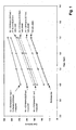
- the electric field strengths of the pure gases required as input for the calculation of the graphical representation of the breakdown fields of several gas mixtures given in Fig. 1 have been determined by performing dielectric tests using a test device which provides representative field conditions, and in particular exemplarily homogenous field conditions. The calculated values are given in dotted lines.
- the breakdown voltage obtained by adding about 100 mbar, more precisely 96 mbar, of the C6-ketone to air (mixture I) is calculated to be increased by about 10% to 15% compared to pure air (and is at 4.0 bars about 140 kV/cm);
- the breakdown voltage obtained by adding about 350 mbar, more precisely 325 mbar, of the C5-ketone to air (mixture II) is calculated to be increased by about 30% to 40% compared to pure air (and is at 4.0 bars about 170 kV/cm)
- the breakdown voltage obtained by adding about 100 mbar of the C6-Ketone and about 350 mbar of the C5-ketone to air (mixture III) is calculated to be increased by about 40% to 50% compared to pure air (and is at 4.0 bars about 190 kV/cm).
- the measured breakdown voltage values are much higher than the calculated values, as is represented in Fig. 1 by the continuous lines.
- This proves that a strong non-linear interaction between the C5-ketone and air or similar gas is present, which strongly improves the dielectric insulation capability, here represented by the electrical breakdown field strengths Ebd in kV/cm, of the gas mixture over the arithmetic sum of the dielectric insulation capabilities, here represented by the electrical field strengths Ebd in kV/cm, of the individual gas mixture components.
- the electrical breakdown field strengths Ebd in kV/cm the electrical breakdown field strengths
- the measured breakdown field obtained for gas mixture II is about 60% to 80% higher than the breakdown field of pure air (and is at 4.0 bars about 230 kV/cm)
- the measured breakdown field obtained for gas mixture III is about 75% to 95% higher than the breakdown field of pure air (and is at 4.0 bars about 260 kV/cm).
- the measured breakdown field obtained for gas mixture I is about 30% to 50% higher than the breakdown field of pure air (and is at 4.0 bar about 180 kV/cm), which is higher than the expected improvements of 10% to 15% for gas mixture I compared to pure air.
- the breakdown field values according to Fig. 1 have been measured performing a standard negative polarity lightning impulse dielectric test using a test device with a homogeneous field arrangement.
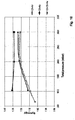
- Fig. 2 shows the filling pressure needed for gas mixtures I, II and III, respectively, for reaching the same insulation performance as SF 6 at 4.5 bar.
- Fig. 2 shows the required filling pressure for different mixtures as a function of temperature.
- Fig. 2 can therefore be read to determine the dielectric insulation medium for operation without liquefaction by: in a first step determining the minimal operating temperature of the dielectric insulation medium or the electric apparatus, respectively; in a second step determining the vapour pressure of each fluoroketone component in the mixture that guarantees no liquefaction of the fluoroketone (s) at the minimal operating temperature; in a third step reading from Fig.
- Fig. 2 furthermore proves that the desired insulation performance, corresponding to 4.5 bars of pure SF 6 , at -5°C is achievable with an insulation medium comprising air, C5-ketone and C6-ketone at a filling pressure of about 6.5 bars.
- a filling pressure is in a usual pressure range of today's gas-insulated switchgear apparatuses or of a part and/or component thereof.
- said insulation medium thus allows to achieve insulation capabilities similar to the one of SF 6 at 4.5 bar without requiring any modification of conventional electrical apparatuses, in particular of enclosures or housings, to withstand such pressures that are not higher than conventional filling pressures.
- an ecologically highly attractive and yet insulation-performance-wise equivalent substitute for conventional high-performance insulation media can thus be provided by setting the filling pressure of a gas mixture comprising air and 5-carbon fluoroketone and optionally 6-carbon fluoroketone to about 6.5 bar.
- the present invention also relates an electrical apparatus, as mentioned above.
- the apparatus comprises a control unit (or "fluid management system") in order to adapt the pressure, the composition and/or the temperature of the insulation medium.
- a control unit or "fluid management system” in order to adapt the pressure, the composition and/or the temperature of the insulation medium. This is of particular relevance for applications in an environment of a temperature as low as -20°C.
- a high voltage switchgear comprising a temperature control unit is shown in Fig. 3 .
- the switchgear 2 comprises a housing 4 defining an insulating space 6 and an electrical active part 8 arranged inside the insulating space 6.
- the switchgear 2 further comprises a temperature control unit 10a for setting the housing 4, or at least a part of the housing 4, of the switchgear 2 and thus the insulation medium comprised in the insulating space 6 to a desired temperature or minimal (or minimal rated) operating temperature T min .
- T min minimal (or minimal rated) operating temperature
- any other part in contact with the insulation medium can be heated in order to bring the insulation medium to the desired temperature.
- the vapour pressure of the fluoroketone - and consequently its partial pressure p a or molar ratio m a in the insulation gas - as well as the absolute pressure p abs of the insulation gas can be adapted accordingly.
- the fluoroketone is in this embodiment not homogenously distributed throughout the insulating space due to the temperature gradient given in the insulation space 6. The concentration of the fluoroketone is thus higher in close proximity to the walls 4' of the housing 4.
- FIG. 4 An alternative control unit or fluid management system is schematically shown in Fig. 4 , in which a fluid handling unit 10b is attributed to the gas-insulated switchgear 2 as the control unit.
- this control unit 10b the composition of the insulation medium, and in particular its concentration of the fluoroketone, in particular fluoroketone a) and/or fluoroketone c), is adjusted in a dosing unit comprised in the fluid handling unit 10b, and the resulting insulation medium is injected or introduced, in particular sprayed, into the insulating space 6.
- the insulation medium is sprayed into the insulating space in the form of an aerosol 14 in which small droplets of liquid fluoroketone are dispersed in the respective carrier gas.
- the aerosol 14 is sprayed into the insulating space 6 by means of nozzles 16 and the fluoroketone is readily evaporated, thus resulting in an insulating space 6 with an inhomogeneous concentration of fluoroketone, specifically a relatively high concentration in close proximity to the housing wall 4' comprising the nozzles 16.
- the insulation medium in particular a concentration, pressure and/or temperature of the fluoroketone a) and/or dielectric insulation gas b) and/or fluoroketone c), can be controlled in the fluid handling unit 10b before being injected into the insulation space.
- the apparatus 2 can have a reserve volume of liquid fluoroketone, in particular fluoroketone a) (or C5-ketone) and/or fluoroketone c) (or C6-ketone), and/or means for limiting a maximal permissible operating temperature of the desired insulation medium such that the absolute filling pressure is maintained below a given pressure limit of the apparatus 2.
- a reserve volume of liquid fluoroketone in particular fluoroketone a) (or C5-ketone) and/or fluoroketone c) (or C6-ketone
- nominal current load generally facilitates the vaporization of the fluoroketone, in particular fluoroketone a) (or C5-ketone) and/or fluoroketone c) (or C6-ketone), by the ohmic heating of current-carrying conductors.
- the use of the temperature control unit is normally only required when the equipment or apparatus (carrying nominal current) does not provide the required temperature for the desired partial pressure of the fluoroketone(s), e.g. at a very low ambient temperature.
- the term "dielectric insulation medium” in this application shall be understood broadly to encompass a gaseous phase and possibly a liquid phase of the dielectric insulation medium.
- the dielectric insulation medium i.e. all components of the dielectric insulation medium, shall be present fully and exclusively in gaseous state under all operating conditions, in particular under all operating temperatures of the electrical apparatus.
- this term shall encompass a medium that has outstanding dielectric insulation capability or dielectric strength, for example in gas-insulated switchgear (GIS) or gas-insulated transmission lines (GITL), and/or has high performance for extinguishing electric arcs, for example arc faults in GIS or GITL or switching arcs in any sort of switch, disconnector, circuit breaker or the like.
- GIS gas-insulated switchgear
- GITL gas-insulated transmission lines
- a dielectric medium comprising a mixture of a fluoroketone containing exactly 5 carbon atoms and a fluoroketone containing exactly 6 carbon atoms and air, in particular C5-fluoroketone, C6-fluoroketone and technical air, here briefly called FCK-air mixture, was used in dielectric test performed in a conventional disconnector of a gas-insulated switchgear (GIS).
- GIS gas-insulated switchgear
- Fig. 5 shows an embodiment of the switchgear 2, here exemplarily a combined disconnector and earthing switch 22, having again a housing 4, a housing wall 4' encapsulating an insulating space 6 filled with the above mentioned gas mixture FCK-air and the active parts 8.
- a gas sensor 24 can be present, as well.
- the disconnector 22 was in a first step evacuated; in a second step C6-fluoroketone was filled into the disconnector 22 up to a pressure of approximately 100 mbar; in a third step C5-fluoroketone was additionally filled into the disconnector 22 up to a total pressure of approximately 460 mbar, i.e.
- the gas sensor 24 for example the gas density sensor 24 or gas pressure sensor 24, is present and allows to control the filling pressures and/or partial gas pressures in the dielectric insulation medium.
- the order of at least the second and third filling step can in principle be exchanged.
- the disconnector 22 is a standard part (ELK-TK14) designed for 300 kV rated voltage, 1050 kV lightning impulse voltage, and 460 kV power frequency withstand voltage, according to IEC standards 62271-203 and 62271-1, with SF 6 filling pressure of 4.5 bars absolute at 20 °C.
- the disconnector 22 with 7 bars FCK-air has passed successfully without flashovers the short-duration power-frequency withstand voltage test for 460 kV rms phase-to-earth, the short-duration power-frequency withstand voltage test for 595 kV rms across isolating distance, i.e. across open contacts of the disconnector 22, and the lightning impulse withstand voltage test for 1050 kV peak voltage.
- the FCK-air mixture containing the fluoroketone with exactly 5 carbon atoms shows an exceptionally high dielectric strength or dielectric withstand voltages also in inhomogeneous electric field arrangements, for example in the electric field distribution present in the disconnector 22 (ELK-TK14).
- Fig. 6 shows arcing times in arbitrary units in a bus transfer current switching test according to IEC 62271-102 performed in the disconnector 22 filled with 7 bars of the above mixture FCK-air (diamonds). Standard test conditions according to IEC 62271-102 have been applied, in particular 1600 A bus transfer current at 20 V bus transfer voltage were applied. Test results with conventional SF 6 dielectric insulation gas at 4.5 bars absolute pressure are shown for comparison (triangles). For better visual comparison, averages of 10 measurement points have been taken and shown as continuous line for FCK-air and as dashed line for SF 6 .
- Fig. 6 proves that the new dielectric insulation medium FCK-air has at least the same bus transfer current switching performance as conventionally used SF 6 . Furthermore, Fig. 6 proves that the new dielectric insulation medium comprising FCK-air at 7 bars absolute pressure has an excellent arc extinction capability, in particular here in the context of bus transfer current switching, which is comparable to or even better than that of SF 6 at 4.5 bars absolute pressure.
- Fig. 7a, 7b show results of temperature rise tests in a section of a bus bar filled with an exemplary insulation medium (diamonds), here C5-fluoroketone at 360 mbar partial pressure plus C6-fluoroketone at 100 mbar partial pressure plus approximately 4.0 bars technical air; and for comparison filled with a conventional insulation medium (triangles), here SF6 at 4.5 bars absolute pressure.
- the temperature rise tests were performed at approximately 20 °C ambient temperature. Tests were performed according to IEC 62271-203 and IEC 62271-1.
- Fig. 7a, 7b show the temperature rise over ambient temperature of the active parts (top figure 7a ) and of the enclosure (bottom figure 7b ) as a function of the thermo element locations.
- Fig. 7a, 7b prove that the thermal performance or heat transfer capability of the FCK-air mixture is comparable to the heat transfer capability of conventional SF 6 .
- FCK-air mixture at higher nominal absolute pressure for example at 7 bars total absolute pressure, an even higher heat transfer capability can be expected.
- the dielectric insulation medium shall contain the fluoroketone comprising exactly 5 carbon atoms in liquid phase in a form different from a bulk liquid at least in the insulation space 6, for example in form of liquid droplets, aerosols, mist, or spray in the insulation space 6.
- Such embodiments may include the dielectric insulation medium with fluoroketone comprising exactly 5 carbon atoms to be in bulk liquid form outside the insulation space 6 of an electrical apparatus 2 e.g. having a fluid management system 10a, 10b.
- any fluoroketone containing exactly 5 carbon atoms for other purposes than as dielectric insulation medium shall be disclaimed from the subject-matter of this application, in particular from the subject-matter claimed in any independent claim and/or in any dependent claim or claim combination, in particular from the claimed dielectric insulation medium, the claimed use of the dielectric insulation medium, and from the claimed apparatus comprising the dielectric insulation medium.
- the dielectric insulation medium of this invention or its use or the electrical apparatus of this invention in particular as claimed in any independent claim and/or in any dependent claim or claim combination, shall not be a dielectric insulation medium for a transformer, or shall not be a transformer, for example not a distribution transformer, not a power transformer, in other examples not a gas transformer, not a liquid transformer, not a dry transformer, and/or not any combination of a gas transformer, liquid transformer and dry transformer.
- the dielectric insulation medium of this invention in particular as claimed in any independent claim and/or in any dependent claim or claim combination, shall not be a working medium for a heat pipe, in particular not a working medium for a heat pipe in a transformer.
- the dielectric insulation medium according to this invention in particular as claimed in any independent claim and/or in any dependent claim or claim combination, does not contain fluoroketone containing exactly 6 carbon atoms, in particular does not contain dodecafluoro-2-methylpentan-3-one (CF 3 CF 2 C(O)CF(CF 3 ) 2 ) with tradename Novec 1230 from 3M.
- fluoroketone containing exactly 6 carbon atoms
- dodecafluoro-2-methylpentan-3-one CF 3 CF 2 C(O)CF(CF 3 ) 2
- Such embodiments may profit from the advantage of lower boiling points of fluoroketones having exactly 5 carbon atoms only.
- toxicity on left-hand side in arbitrary units and of boiling point or boiling point temperature T p (on right-hand side) as a function of the number of carbon atoms contained in the fluoroketone, in particular in fluoroketone a) and/or fluoroketone c).
- a maximal permissible toxicity level is indicated by the horizontal dashed bold line, and a maximal permissible level of boiling point is indicated by the horizontal dashed thin line.
- toxicity decreases with increasing number of carbon atoms such that fluoroketones having 5 or more carbon atoms are permissible due to being sufficiently non-toxic.
- the boiling point is increasing with increasing number of carbon atoms such that fluoroketones having 7 or less carbon atoms are useful in typical technical applications, whereas fluoroketones having 8 or more carbon atoms are considered to be less useful or not useful due to too high boiling points. Therefore, in view of non-toxicity and low boiling point, fluoroketones having from 5 to 7 carbon atoms are preferred.
- Fig. 9 shows a schematic diagram of cross-sections (measured e.g. in m 2 ) for electron scattering in the carrier gas, in particular in the dielectric insulation gas component b), and for ionization in the fluoroketone, in particular in the fluoroketone a) and/or fluoroketone c), as a function of electron energy (measured e.g. in eV).
- a possible mechanism of the nonlinearly increased dielectric strength can be that the dielectric gas component b) (which is or comprises the carrier gas) serves for decelerating electrons, which stem from dielectric breakdown, and the fluoroketone a), and possibly fluoroketone c), serves for capturing such decelerated electrons, thus establishing an excessively high dielectric strength of the gas mixture containing fluoroketone a), and possibly fluoroketone c), and the carrier gas b).
- the dielectric insulation gas component b) according to the present invention shall thus in particular encompass gases which are capable of decelerating electrons.
- Such a mechanism may occur preferably, if the carrier gas has a high inelastic electron scattering cross-section at energies below the ionization threshold of the fluoroketone, in particular of fluoroketone a) and/or c).
- a situation is exemplarily shown in Fig. 9 where the peak of electron scattering cross-section of the carrier gas lies energetically below the ionization threshold, which threshold designates the low-energy edge of a substantial rise in the ionization cross-section characteristics of the fluoroketone.
- carrier gas or bulk gas can be equal to the dielectric insulation gas component b) or may be one of the dielectric insulation gas component elements b2) of the dielectric insulation gas component b).
- the apparatus 2 has a dielectric insulation medium, in which the fluoroketone, in particular at least one fluoroketone a) and optionally the further fluoroketone c), is present in an amount such that a condensation temperature of the fluoroketone is below +5 °C, preferably below -5 °C, more preferably below -20 °C, even more preferably below -30 °C, most preferably below-40 °C.
- the apparatus 2 has a dielectric insulation medium, which comprises gaseous components in molar volumes or volume concentrations or number densities or molar fractions m a or partial pressures p a such that a condensation temperature of the mixture of the gaseous components is below +5 °C, preferably below -5 °C, more preferably below -20 °C, even more preferably below -30 °C, most preferably below -40 °C.
- boiling point or boiling point temperature relates to the vapour pressure curve of a component of the insulation medium as a function of temperature, and in particular to the boiling point (temperature) at atmospheric pressure, i.e. at about 1 bar. This is a property of the component as such and describes its vaporization and liquefaction behaviour in particular under atmospheric surrounding pressure conditions.
- condensation temperature relates to a specific apparatus providing a volume for receiving the dielectric insulation medium, its filling with a specific dielectric insulation medium, in particular the type and amount of the component or components of the dielectric insulation medium, at a given temperature, e.g. the operating temperature or the minimal rated operating temperature, and to the corresponding total pressure of the dielectric insulation medium and the partial pressures of its components.
- a specific apparatus environment may comprise surface roughnesses, electric field inhomogeneities and other factors relevant for dielectric withstand capability or dielectric strength.
- condensation temperature defines the temperature at which a gaseous part or phase of the dielectric insulation medium, in particular a group of components in gaseous phase of the dielectric insulation medium, starts to condense into droplets that sit down on inner surfaces of the apparatus and form a liquid "sea" thereon.
- condensation temperature a common condensation temperature, briefly called condensation temperature, of components of the dielectric insulation medium, even if the boiling points of such components in their pure form may differ by e.g. several 10 K or even by some 50 K.
- condensation temperature the molar fractions of the components in the gaseous phase and in the liquid phase may vary when condensation starts.
- condensation temperature is an integral parameter describing the specific apparatus having a specific filling with the dielectric insulation medium and under specific operating conditions.
- the condensation temperature is determined solely by the nature and number density or molar volume (m 3 /mol) or volume concentration of the dielectric insulation gas component or components under consideration.
- the number density or molar volume or molar fraction corresponds to the partial pressures (e.g. p a ) present in the apparatus at a given temperature.
- the parameters "type of dielectric gas component or gas components” and “number density or molar volumes or partial pressures” determine at what temperature a gas or group of gas components will condense.
- the dielectric insulation medium in particular the choice of its types and amounts of components, and by the choice of pressures, i.e. partial pressures of the components and the total pressure, possibly by additional filling of a carrier gas or bulk gas, and by the choice of operating conditions, such as temperature.
- the avoidance of condensation is expressed by the fact that the condensation temperature shall be lower than a minimal operating temperature or a minimal rated operating temperature T min of the apparatus, e.g. lower than +5°C, or -5°C, or -20°C, or -30°C, or -40°C, as stated above.
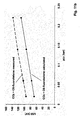
- Fig. 10 shows the non-linear or synergy factor s achieved by exemplary dielectric insulation media according to the present invention.
- the synergy factor s is shown for a first mixture C5-fluoroketone plus air (diamonds), a second mixture C6-fluoroketone plus air (squares), and a third mixture C5-fluoroketone plus C6-fluoroketone plus air (triangles) as a function of the total pressure p abs , with the partial pressure p a of the fluoroketone being kept constant.
- the second mixture has relatively higher synergy factors of about 1.3 over a wide range of total pressures.
- the synergy factor s is relatively low when the ratio of fluoroketone to air is high and increases with a decrease in the ratio of molar fractions m a or partial pressures p a of fluoroketone(s) to dielectric gas component b), here to air.
- the breakdown voltage U50 is defined as the 50% probability of breakdown when a typical lightning impulse, e.g. of 1.2 ⁇ s rise and 50 ⁇ s fall, with positive polarity is applied in a principal test device with a homogeneous electrode arrangement.
- the partial pressures of the fluoroketones FKs have been kept constant and were exemplarily chosen to be 0.1 bar C6-fluoroketone and 0.36 bar C5-fluoroketone.
- the CO 2 content was then filled up to the total pressure p indicated on the x-axis. Linear extrapolation lines were drawn to show a trend line for lower absolute pressures p.
- Fig. 11b also shows the existence of the synergistic or non-linear effect achieved by the present invention for a dielectric insulation gas mixture of C6-fluoroketone with carbon dioxide CO 2 .
- Fig. 11b shows the breakdown voltage U50 in kV, measured with lightning impulses in a different measurement apparatus, as a function of the partial pressure p C6 of the C6-fluoroketone, with the total pressure p abs being kept constant at 1 bar.
- a strong non-linear increase of the measured dielectric strength of the mixture (diamonds) over the linearly calculated sum of dielectric strengths of the single components, C6 and CO 2 , (squares) is proven.
- Fig. 12 further illustrates the non-linear increase in dielectric strength of a gas mixture of C5-fluoroketone with air.
- p c5 vapour pressure of C5-fluoroketone at temperature T
- pair partial pressure of air
- E crit,a of the C5-fluoroketone is 180 kV/(cm*bar)
- E crit,b of air is 30 kV/(cm*bar).
- the condensation temperature of a given gas mixture depends on the vapour pressure of the high-boiling component, here the C5-fluoroketone. Hence, for a minimum operating temperature of an electrical apparatus of -5°C the partial pressure of the high-boiling component must lie at or below its vapour pressure at -5°C.
- the condensation temperature T cond on the y-axis corresponds to a partial pressure p a or molar fraction m a of the fluoroketone, here C5-fluoroketone, which correspondence is established via the vapour pressure curve of the fluoroketone, here C5-fluoroketone.
- Such condensation temperature T cond may also correspond to a minimal operating temperature of the electrical apparatus, as discussed above, when liquefaction shall be avoided.
- Fig. 12 the small diamonds show measured values of dielectric strengths of the mixture, and the lines show trend lines calculated with the aid of the vapour pressure curve of the C5-fluoroketone.
- r p C5 /p air , e.g.
- a synergy factor higher than 1 is in the example shown in Fig 12 obtained for a partial pressure ratio p a to p b of 0.04:1, 0.14:1, 0.22:1, and 0.56:1.
- the ratio r can be selected in a range of 0.01 ⁇ r ⁇ 0.8, preferably 0.02 ⁇ r ⁇ 0.7, more preferably 0.04 ⁇ r ⁇ 0.6.
- a high or ultra-low proportion of C5-fluoroketone results in a low synergy factor (close to 1).
- An intermediate or lower than high proportion of C5-fluoroketone results in a synergy factor s significantly higher than 1.
- the presence of synergy expressed as the synergy factor s being larger than 1, permits operation of an electrical apparatus at higher electric breakdown field strengths Ebd and/or down to lower temperatures than if no synergy were present.
- the amount of fluoroketone and/or dielectric gas component b) may be reduced, when a synergy factor larger than 1 is present.
- carrier gas or bulk gas or buffer gas which may be comprised in or may be the above mentioned gas component b) or gas component element b1), b2), ... bn) different from the fluoroketone, shall signify a gaseous part of the dielectric insulation medium that contributes to the dielectric strength, but typically has a dielectric strength weaker than the dielectrically more active or stronger fluoroketone(s).
- carrier gas e.g. air, nitrogen, or carbon dioxide, typically has a condensation temperature well below the condensation temperature T cond of the fluoroketone(s).
- the constituents or components of the dielectric insulation medium such as various kinds of fluoroketones and carrier gases, are herewith explicitly disclosed to be possible or to be present in any combinations, may it be pair-wise combinations, triplet-wise combinations, quadruplet-wise combinations, or the like. Therefore, any listings of all such combinations are herewith made part of the disclosure.
Claims (50)
- Dielektrisches Isoliermedium, das ein dielektrisches Isoliergas umfasst, wobei das Isoliergas Folgendes enthält:a) ein Fluorketon a), das genau 5 Kohlenstoffatome enthält, in einer Mischung mitb) einer dielektrischen Isoliergaskomponente b), die von dem Fluorketon a) verschieden ist,
wobei die dielektrische Gaskomponente b) ein Trägergas ist, das in einer größeren Quantität als das Fluorketon a) vorhanden ist und das zusammen mit dem Fluorketon a) eine nichtlineare Zunahme der dielektrischen Festigkeit des Isoliermediums über die Summe der dielektrischen Festigkeiten der Gaskomponenten des Isoliermediums bereitstellt. - Dielektrisches Isoliermedium nach Anspruch 1, wobei die dielektrische Isoliergaskomponente b) ein Trägergas ist, das selber eine niedrigere dielektrische Festigkeit hat als das Fluorketon a).
- Dielektrisches Isoliermedium nach einem der vorhergehenden Ansprüche, wobei ein Typ und eine Menge der Gaskomponente b) und eine Menge des Fluorketons a) so ausgewählt sind, dass die nichtlineare Zunahme der dielektrischen Festigkeit des Isoliermediums über die Summe der dielektrischen Festigkeiten der Gaskomponenten des dielektrischen Isoliermediums erreicht wird.
- Dielektrisches Isoliermedium nach einem der vorhergehenden Ansprüche, wobei eine Durchschlagfeldstärke Ebd des dielektrischen Isoliermediums, insbesondere der Mischung seiner Gaskomponenten, durch die folgende Gleichung definiert ist:

in derpa ein Partialdruck des Fluorketons a) ist,pb ein Partialdruck der dielektrischen Isoliergaskomponente b) ist,Ecrit,a eine druckreduzierte elektrische Durchschlagfeldstärke des Fluorketons a) ist,Ecrit,b eine druckreduzierte elektrische Durchschlagfeldstärke der dielektrischen Isoliergaskomponente b) ist,s ein Synergiefaktor Ebdmeasured/Ebdlin.calc. ist, wobei Ebdmeasured eine gemessene Durchschlagfeldstärke des dielektrischen Isoliermediums, insbesondere der Mischung seiner Gaskomponenten, ist und Ebdlin.calc. eine linear berechnete Summe der elektrischen Durchschlagfeldstärken des Fluorketons a) und der dielektrischen Gaskomponente b) ist,wobei die Mischung so ausgewählt ist, dass der Synergiefaktor größer als 1 ist. - Dielektrisches Isoliermedium nach Anspruch 4, wobei ein Typ und eine Menge der Gaskomponente a) und eine Menge des Fluorketons a) so ausgewählt ist, dass der Synergiefaktor größer als 101 %, bevorzugt größer als 105 %, stärker bevorzugt größer als 110 %, am stärksten bevorzugt größer als 115 % ist.
- Dielektrisches Isoliermedium nach einem der Ansprüche 4-5, wobei der Synergiefaktor s von dem Verhältnis r des Partialdrucks pa des Fluorketons a) zu dem Partialdruck pb der dielektrischen Isoliergaskomponente b) abhängig ist.
- Dielektrisches Isoliermedium, das Folgendes umfasst:a) ein Fluorketon a), das genau 5 Kohlenstoffatome enthält, in einer Mischung mitb) einer dielektrischen Isoliergaskomponente b), die von dem Fluorketon a) verschieden ist,
wobei die dielektrische Gaskomponente b) ein Trägergas ist, das in einer größeren Quantität als das Fluorketon a) vorhanden ist und das zusammen mit dem Fluorketon a) eine nichtlineare Zunahme der dielektrischen Festigkeit des Isoliermediums über die Summe der dielektrischen Festigkeiten der Gaskomponenten des Isoliermediums bereitstellt,
wobei die dielektrische Gaskomponente b) Luft oder eine Luftkomponente, insbesondere Stickstoff, ist oder enthält. - Dielektrisches Isoliermedium nach Anspruch 7, wobei die dielektrische Isoliergaskomponente b) Sauerstoff enthält und/oder die dielektrische Isoliergaskomponente b) Kohlenstoffdioxid enthält bzw. insbesondere ist.
- Dielektrisches Isoliermedium nach Anspruch 8, wobei das dielektrische Isoliermedium ein bogenlöschendes Gas, insbesondere für einen Leistungsschalter, ist.
- Dielektrisches Isoliermedium nach einem der Ansprüche 7 bis 9, wobei der molare Anteil von Sauerstoff bei oder unter 40 %, bevorzugt unter 30 %, stärker bevorzugt unter 20 % liegt.
- Dielektrisches Isoliermedium nach einem der vorhergehenden Ansprüche, wobei das Fluorketon a) ein Perfluorketon ist und/oder das Fluorketon a) eine verzweigte Alkylkette besitzt und/oder das Fluorketon a) eine vollständig gesättigte Verbindung ist.
- Dielektrisches Isoliermedium nach einem der vorhergehenden Ansprüche, wobei das Fluorketon a) mindestens eine Verbindung ist, die aus der Gruppe ausgewählt ist, die aus den Verbindungen besteht, die durch die folgenden Strukturformeln definiert sind, in denen mindestens ein Wasserstoffatom durch ein Fluoratom ersetzt ist:


- Dielektrisches Isoliermedium nach einem der vorhergehenden Ansprüche, wobei das Fluorketon a) die Molekularformel C5F10O hat und insbesondere aus der Gruppe ausgewählt ist, die aus 1,1,1,3,4,4,4-Heptafluor-3-(trifluormethyl)butan-2-on, 1,1,1,3,3,4,4,5,5,5-Decafluorpentan-2-on, 1,1,1,2,2,4,4,5,5,5-Decafluorpentan-3-on und 1,1,1,4,4,5,5,5-Octafluor-3-bis(trifluormethyl)-pentan-2-on besteht, und bevorzugt 1,1,1,3,4,4,4-Heptafluor-3-(trifluormethyl)butan-2-on ist.
- Dielektrisches Isoliermedium nach einem der vorhergehenden Ansprüche, wobei der molare Anteil des Fluorketons a) in dem Isoliermedium größer als 1 %, bevorzugt größer als 2 %, stärker bevorzugt größer als 3 %, insbesondere größer als 3,5 % ist, der molare Anteil des Fluorketons a) in dem Isoliermedium sogar stärker bevorzugt von 5 % bis 40 %, am stärksten bevorzugt von 6 % bis 10 % reicht; und/oder wobei sich das Fluorketon a) unter Betriebsbedingungen in dem Isoliermedium in einer gasförmigen Phase befindet.
- Dielektrisches Isoliermedium nach einem der vorhergehenden Ansprüche, wobei das dielektrische Isoliermedium ein dielektrisches Isoliergas unter einem Überdruck von weniger als 8 bar, bevorzugt weniger als 7,5 bar, stärker bevorzugt weniger als 7 bar, insbesondere gleich oder weniger als 6,5 bar ist; oder wobei das dielektrische Isoliermedium ein dielektrisches Isoliergas unter einem Überdruck von weniger als 2,5 bar, bevorzugt weniger als 2,0 bar, stärker bevorzugt weniger als 1,5 bar, insbesondere gleich oder weniger als 1,2 bar ist.
- Dielektrisches Isoliermedium nach einem der vorhergehenden Ansprüche, wobei die dielektrische Isoliergaskomponente b) einen atmosphärischen Siedepunkt von mindestens 50 K, bevorzugt mindestens 70 K, insbesondere mindestens 100 K unter einem atmosphärischen Siedepunkt des Fluorketons a) hat.
- Dielektrisches Isoliermedium nach einem der vorhergehenden Ansprüche, wobei die dielektrische Isoliergaskomponente b)A) inert und/oder ungiftig und/oder nicht entflammbar ist; und/oderB) eine dielektrische Festigkeit von mehr als 10 kV/(cm bar), bevorzugt mehr als 20 kV/(cm bar), insbesondere mehr als 30 kV/(cm bar) hat; und/oderC) ein Ozonabbaupotential von 0 hat; und/oderD) die dielektrische Isoliergaskomponente b) ein Treibhauspotential GWP über 100 Jahre von weniger als 1000, bevorzugt weniger als 300, bevorzugt weniger als 100, bevorzugt weniger als 50, bevorzugt weniger als 10, bevorzugt weniger als 5, bevorzugt weniger als 3, stärker bevorzugt weniger als 2, am stärksten bevorzugt weniger als 1,5 hat; und/oderE) die dielektrische Isoliergaskomponente b) Moleküle mit weniger Atomen enthält, als in dem Fluorketon a) vorhanden sind, insbesondere dreiatomige und/oder zweiatomige Moleküle enthält oder aus dreiatomigen und/oder zweiatomigen Molekülen besteht.
- Dielektrisches Isoliermedium nach einem der vorhergehenden Ansprüche, wobei die dielektrische Isoliergaskomponente b) eine Mischung von mindestens zwei Gaskomponentenelementen b1), b2), ..., bn) enthält.
- Dielektrisches Isoliermedium nach einem der vorhergehenden Ansprüche, wobei das Fluorketon a) einen energieabhängigen Ionisationswirkungsquerschnitt mit einem Ionisationsenergieschwellenwert hat, die dielektrische Isoliergaskomponente b) einen energieabhängigen Elektronenstreuquerschnitt mit einer Spitze bei einer spezifischen Energie hat, wobei die spezifische Energie der dielektrischen Isoliergaskomponente b) unter dem Ionisationsenergieschwellenwert des Fluorketons a) liegt.
- Dielektrisches Isoliermedium nach einem der vorhergehenden Ansprüche, das ferner Folgendes umfasst:c) ein weiteres Fluorketon c), das von dem Fluorketon a) verschieden ist.
- Dielektrisches Isoliermedium nach Anspruch 20, wobei das weitere Fluorketon c) von der dielektrischen Isoliergaskomponente b) verschieden ist.
- Dielektrisches Isoliermedium nach einem der Ansprüche 20 bis 21, wobei das weitere Fluorketon c) genau 5 Kohlenstoffatome oder genau 6 Kohlenstoffatome oder genau 7 Kohlenstoffatome oder genau 8 Kohlenstoffatome enthält, bevorzugt von 5 bis 7 Kohlenstoffatomen enthält, bevorzugt genau 6 Kohlenstoffatome enthält; insbesondere wobei das weitere Fluorketon c) mindestens eine Verbindung ist, die aus der Gruppe ausgewählt ist, die aus den Verbindungen besteht, die durch die folgenden Strukturformeln definiert sind, in denen mindestens ein Wasserstoffatom durch ein Fluoratom ersetzt ist:


- Dielektrisches Isoliermedium nach einem der Ansprüche 20 bis 22, wobei das Fluorketon c) ein Perfluorketon ist und/oder das Fluorketon c) eine verzweigte Alkylkette besitzt und/oder das Fluorketon c) eine vollständig gesättigte Verbindung ist.
- Dielektrisches Isoliermedium nach einem der Ansprüche 20 bis 23, wobei das Fluorketon c) die Molekularformel C6F12O hat und insbesondere aus der Gruppe ausgewählt ist, die aus 1,1,1,2,4,4,5,5,5-Nonafluor-2-(trifluormethyl)pentan-3-on (auch Dodecafluor-2-methylpentan-3-on genannt), 1,1,1,3,3,4,5,5,5-Nonafluor-4-(trifluormethyl)pentan-2-one (auch Dodecafluor-4-Methylpentan-2-one genannt), 1,1,1,3,4,4,5,5,5-Nonafluor-3-(trifluormethyl)pentan-2-on (auch Dodecafluor-3-methylpentan-2-on genannt), 1,1,1,3,4,4,4-Heptafluor-3,3-Bis-(trifluormethyl)butan-2-on (auch Dodecafluor-3,3-(dimethyl)butan-2-on genannt), Dodecafluorhexan-2-on und Dodecafluorhexan-3-on und Decafluor-Cyclohexanon besteht, und insbesondere 1,1,1,2,4,4,5,5,5-Nonafluor-2-(trifluormethyl)pentan-3-on ist.
- Dielektrisches Isoliermedium nach einem der Ansprüche 20 bis 24, wobei der molare Anteil des Fluorketons c) in dem Isoliermedium größer als 0,1 %, bevorzugt größer als 0,5 %, stärker bevorzugt größer als 1 %, insbesondere größer als 2 % ist; und/oder der molare Anteil des Fluorketons c) in dem Isoliermedium von 1 % bis 15 %, bevorzugt von 1 % bis 10 %, stärker bevorzugt von 1 % bis 3 % reicht.
- Dielektrisches Isoliermedium nach einem der vorhergehenden Ansprüche, wobei der Partialdruck von jeder Fluorketonkomponente mindestens ungefähr seinem jeweiligen gesättigten Dampfdruck bei einer minimalen Betriebstemperatur des dielektrischen Isoliermediums entspricht.
- Dielektrisches Isoliermedium nach einem der vorhergehenden Ansprüche, wobei das Verhältnis des molaren Anteils von Sauerstoff zu dem molaren Anteil von dem mindestens einen Fluorketon a) und optional des weiteren Fluorketons c) mindestens 2:1, bevorzugt mindestens 2,5:1, stärker mindestens bevorzugt 3:1 ist; und/oder das dielektrische Isoliermedium, insbesondere das dielektrische Isoliergas, ein Treibhauspotential GWP über 100 Jahre von weniger als 100, bevorzugt weniger als 50, bevorzugt weniger als 20, bevorzugt weniger als 10, bevorzugt weniger als 5, bevorzugt weniger als 3, stärker bevorzugt weniger als 2, am stärksten bevorzugt weniger als 1,5 hat.
- Verwendunga) eines Fluorketons a), das genau 5 Kohlenstoffatome enthält, in einer Mischung mitb) einer elektrischen Isoliergaskomponente b), die von dem Fluorketon a) verschieden ist, wobei die dielektrische Isoliergaskomponente b) ein Trägergas ist, das in einer größeren Quantität als das Fluorketon a) vorhanden ist und das zusammen mit dem Fluorketon a) eine nichtlineare Zunahme der dielektrischen Festigkeit des Isoliermediums über die Summe der dielektrischen Festigkeiten der Gaskomponenten des Isoliermediums bereitstellt,
als ein dielektrisches Isoliermedium für eine Vorrichtung für die Erzeugung und/oder Übertragung und/oder Verteilung und/oder Benutzung von elektrischer Energie, insbesondere für eine gasisolierte Schaltanlage mit hoher oder mittlerer Spannung, wobei das dielektrische Isoliermedium kein Fluorketon enthält, das genau 6 Kohlenstoffatome enthält. - Verwendung des dielektrischen Isoliermediums nach einem der Ansprüche 1 bis 27, wobei Anspruch 24 ausgeschlossen ist, in einer Vorrichtung für die Erzeugung und/oder Übertragung und/oder Verteilung und/oder Benutzung von elektrischer Energie.
- Verwendung nach einem der Ansprüche 28 bis 29, wobei die minimal zulässige Betriebstemperatur der gasisolierten Schaltanlage -5 °C ist; und/oder wobei die Verwendung in einer inhomogenen Verteilung eines elektrischen Felds stattfindet.
- Verwendung des dielektrischen Isoliermediums nach einem der Ansprüche 28 bis 30, wobei die Mischung ferner c) ein weiteres Fluorketon c) umfasst, das von dem Fluorketon a) verschieden ist.
- Verwendung eines dielektrischen Isoliermediums nach einem der Ansprüche 1 bis 27, wobei die Verwendunga) das Fluorketon a) in einer Mischung mitb1) Kohlenstoffdioxid und/oderb2) Luft oder Sauerstoff
als einem bogenlöschenden Gas in einem Leistungsschalter, insbesondere in einem Hochspannungs-Leistungsschalter oder einem Mittelspannungs-Leistungsschalter, umfasst. - Verwendung nach Anspruch 32, wobei die Luft oder der Sauerstoff in dem bogenlöschenden Gas zum Verringern der Kohlenstoffablagerung auf den Elektroden des Leistungsschalters dient; und/oder die Luft oder der Sauerstoff in dem bogenlöschenden Gas zum Verringern einer Menge von giftigen Nebenprodukten der Bogenbildung, die insbesondere nach einem Schaltvorgang vorhanden sind, dient; und/oder das Fluorketon a) genau 5 oder genau 6 oder genau 7 oder genau 8 Kohlenstoffatome enthält.
- Verwendung nach einem der Ansprüche 32 bis 33, wobei das Verhältnis der Menge von Kohlenstoffdioxid zu der Menge von Sauerstoff höchstens 20:1, bevorzugt höchstens 15:1, stärker bevorzugt höchstens 10:1, am stärksten höchstens 5:1 ist und/oder das Verhältnis des molaren Anteils von Sauerstoff zu dem molaren Anteil von Fluorketon a) und optional dem weiteren Fluorketon c) mindestens 2:1, bevorzugt 2,5:1, stärker bevorzugt mindestens 3:1 ist.
- Vorrichtung (2) für die Erzeugung und/oder Übertragung und/oder Verteilung und/oder Benutzung von elektrischer Energie, insbesondere eine Vorrichtung (2) für eine mittlere oder hohe Spannung, wobei die Vorrichtung (2) ein Gehäuse (4) umfasst, das einen Isolierraum (6) und einen elektrischen aktiven Teil (8), der in dem Isolierraum (6) angeordnet ist, definiert, wobei der Isolierraum (6) ein Isoliermedium umfasst, das durch das dielektrische Isoliermedium nach einem der Ansprüche 1 bis 27 gekennzeichnet ist.
- Vorrichtung (2) nach Anspruch 35, dadurch gekennzeichnet, dass die Vorrichtung (2) eine Schaltanlage (2) ist, insbesondere eine luftisolierte oder eine gasisolierte metallgekapselte Schaltanlage (2) oder eine Hybridschaltanlage oder eine Mittelspannungs-Blockschaltanlage oder eine Ringleitungseinheit, oder ein Kesselleistungsschalter oder ein PASS-Modul (ein Modul zum Anschließen und Schalten), oder ein Teil oder eine Komponente davon, insbesondere eine Sammelschiene, eine Durchführung, ein Kabel, ein gasisoliertes Kabel, eine Kabelverbindung, ein Stromwandler, ein Spannungswandler, ein Überspannungsableiter und/oder eine gasisolierte Übertragungsleitung.
- Vorrichtung (2) nach einem der Ansprüche 35 bis 36, dadurch gekennzeichnet, dass die Vorrichtung (2) ein Schalter ist, insbesondere ein Erdungsschalter, ein Trennschalter, ein kombinierter Trenn- und Erdungsschalter, ein Lasttrennschalter und/oder ein Leistungsschalter.
- Vorrichtung (2) nach Anspruch 37, gekennzeichnet dadurch, dass die Vorrichtung ein Hochspannungs-Leistungsschalter ist, der eine Druckaufbaukammer besitzt, um ein druckbeaufschlagtes bogenlöschendes Gas bereitzustellen,
die insbesonderea) Fluorketon a) in einer Mischung mitb1) Kohlenstoffdioxid und/oderb2) Luft oder Sauerstoff umfasst,
und dass bei einem Schaltvorgang während einer bogenlöschenden Phase das Fluorketon in Fluorkohlenstoffverbindungen abgebaut wird, die eine niedrigere Anzahl von Kohlenstoffatomen haben. - Vorrichtung (2) nach einem der Ansprüche 35 bis 36, dadurch gekennzeichnet, dass die Vorrichtung ein Transformator ist, insbesondere ein Verteilungstransformator oder ein Leistungstransformator, oder die Vorrichtung eine drehende elektrische Maschine, ein Generator, ein Motor, ein Antrieb, eine Halbleitereinrichtung und/oder eine Leistungselektronikeinrichtung ist.
- Vorrichtung (2) nach einem der Ansprüche 35 bis 39, dadurch gekennzeichnet, dass sie ferner eine Steuereinheit (10a, 10b) umfasst zum individuellen Steuern oder Steuern in Kombination: jeweils einer Zusammensetzung, einer Temperatur, eines Absolutdrucks, eines Partialdrucks, einer Gasdichte und/oder einer Teilgasdichte des Isoliermediums oder mindestens einer seiner Komponenten.
- Vorrichtung (2) nach Anspruch 40, dadurch gekennzeichnet, dass die Steuereinheit (10a, 10b) eine Heizung und/oder einen Verdampfer (16) zum Steuern des Partialdrucks des Fluorketons a) und des optionalen Fluorketons c), insbesondere um ihn über einem benötigten Partialdruckpegel zu halten, umfasst; und/oder die Steuereinheit (10a, 10b) eine Temperatursteuereinheit (10a) umfasst, die ein Heizsystem zum Einstellen des Gehäuses (4), oder mindestens eines Teils des Gehäuses (4), der Vorrichtung (2) auf eine gewünschte Temperatur umfasst; und/oder die Steuereinheit (10a, 10b) eine Fluiddosierungseinheit (10b) zum Dosieren einer Konzentration des Fluorketons a) und des optional weiteren Fluorketons c) und zum Einspritzen des resultierenden Isoliermediums in die Vorrichtung (2) umfasst.
- Vorrichtung (2) nach einem der Ansprüche 35 bis 41, dadurch gekennzeichnet, dass die Vorrichtung (2) ein Reservevolumen von flüssigem Fluorketon besitzt; und/oder Mittel zum Begrenzen einer maximal zulässigen Betriebstemperatur des gewünschten Isoliermediums besitzt, so dass der absolute Fülldruck unter einer gegebenen Druckgrenze der Vorrichtung (2) gehalten wird, und/oder die Vorrichtung (2) eine inhomogene Verteilung eines elektrischen Felds hat; und/oder die Vorrichtung ein herkömmliches Druckdesign hat, um mit Schwefelhexafluorid SF6 gefüllt zu sein, und stattdessen mit dem dielektrischen Isoliermedium nach einem der Ansprüche 1 bis 27 gefüllt ist.
- Vorrichtung (2) nach einem der Ansprüche 35 bis 42, dadurch gekennzeichnet, dass das dielektrische Isoliermedium Fluorketon a) und das optional weitere Fluorketon c) in einer Menge vorhanden sind, so dass eine Kondensationstemperatur des Fluorketons unter einer Nennbetriebstemperatur der Vorrichtung (2) liegt, insbesondere unter +5 °C, bevorzugt unter -5 °C, stärker bevorzugt unter -20 °C, noch stärker bevorzugt unter -30 °C, am stärksten bevorzugt unter -40 °C; und/oder das dielektrische Isoliermedium gasförmige Komponenten in einer Menge umfasst, so dass eine Kondensationstemperatur der Mischung der gasförmigen Komponenten unter einer Nennbetriebstemperatur der Vorrichtung (2), insbesondere unter +5 °C, bevorzugt unter -5 °C, stärker bevorzugt unter -20 °C, noch stärker bevorzugt unter -30 °C, am stärksten bevorzugt unter-40 °C liegt.
- Vorrichtung (2) nach einem der Ansprüche 35 bis 43,a) wobei die Vorrichtung einer Leistungsklasse angehört, die durch Leistungsparameter gekennzeichnet ist, die eine elektrische Feldstärke Eapp, die in einem Raum, der durch das dielektrische Isoliermedium gefüllt ist, erforderlich ist, eine minimale Nennbetriebstemperatur Tmin, eine maximale Nennbetriebstemperatur Tmax und einen maximal zulässigen Gasdruck pmax umfassen,b) wobei die Vorrichtung ein dielektrisches Isoliergas umfasst, das ein Fluorketon in einer Mischung mit einer dielektrischen Isoliergaskomponente b), die von dem Fluorketon verschieden ist, enthält, wobei die Mischung eine nichtlinear zunehmende dielektrische Festigkeit hat, die durch einen Synergiefaktor s gekennzeichnet ist,c) wobei das dielektrische Isoliergas, insbesondere die Mischung, charakteristische Parameter hat, die durch eine Art, einen Partialdruck pa, oder insbesondere eine entsprechende Teilchendichte, und eine druckreduzierte elektrische Durchschlagsfeldstärke Ecrit,a des Fluorketons und eine Art, einen Partialdruck pb, oder insbesondere eine entsprechende Teilchendichte, und eine druckreduzierte elektrische Durchschlagsfeldstärke Ecrit,b der dielektrischen Isoliergaskomponente b) definiert sind,d) wobei eine lineare druckreduzierte Durchschlagsfeldstärke Ebdlin.calc. des dielektrischen Isoliergases, insbesondere der Mischung, als eine Funktion des Partialdrucks pa des Fluorketons durch eine partialdruckgewichtete Summe der druckreduzierten elektrischen Durchschlagfeldstärken Ecrit,a und Ecrit,b berechnet wird,e) wobei aus der elektrischen Feldstärke Eapp und aus der linearen druckreduzierten Durchschlagfeldstärke Ebdlin.calc. eine Absolutdruckkurve pabs(pa) des dielektrischen Isoliergases als eine Funktion der Partialdrücke pa des Fluorketons bestimmt wird,f) wobei ein absoluter Fülldruck pabs des Isoliergases bei einer Normaltemperatur und daraus und aus der Absolutdruckkurve pabs(pa) ein erster Partialdruck pa1, oder insbesondere eine erste entsprechende Teilchendichte, des Fluorketons bestimmt wird undg) wobei mindestens einer der Leistungsparameter der elektrischen Vorrichtung aufgrund dessen, dass der Synergiefaktor der Mischung größer als 1 ist, erweitert wird.
- Vorrichtung (2) nach Anspruch 44,a) wobei ein zweiter Partialdruck pa2, oder insbesondere eine zweite entsprechende Teilchendichte, des Fluorketons so bestimmt wird, dass eine Kondensationstemperatur des Fluorketons in dem Isoliergas unter der minimalen Nennbetriebstemperatur Tmin liegt, undb) wobei dann, wenn der erste Partialdruck pa1 gleich oder niedriger als der zweite Partialdruck pa2 ist, der Partialdruck pa des Fluorketons in einem Bereich so ausgewählt wird, dass pa1 ≤ pa ≤ pa2 gilt, oderc) wobei dann, wenn der erste Partialdruck pa1 größer als der zweite Partialdruck pa2 ist,i. der Partialdruck pa des Fluorketons kleiner als oder gleich dem zweiten Partialdruck pa2 gewählt wird und durch Erhöhen des Partialdrucks pb der dielektrischen Isoliergaskomponente b) der Absolutdruck pabs erhöht wird, insbesondere der Absolutdruck pabsauf einen Wert gleich pabs (Pa2) erhöht wird, und/oderii. die minimale Betriebstemperatur Tmin durch Erwärmen und dadurch der zweite Partialdruck pa2 auf einen höheren Wert erhöht wird, und insbesondere der zweite Partialdruck pa2 auf einen Wert gleich oder über dem ersten Partialdruck pa1 erhöht wird, und dann der Partialdruck pa des Fluorketons in einem Bereich so ausgewählt ist, dass pa1 ≤ pa ≤ pa2 gilt.
- Vorrichtung (2) nach einem der Ansprüche 44-45, wobeia) ein Wert des Synergiefaktors s für die Mischung bestimmt wird, insbesondere für ein Verhältnis des Partialdrucks pa des Fluorketons zu dem Partialdruck pb der dielektrischen Gaskomponente b), die in der elektrischen Vorrichtung (2) vorhanden ist, undb) eine Auslegungserweiterung durch mindestens eine der folgenden Maßnahmen durchgeführt wird: die maximale elektrische Feldstärke Eapp wird erhöht, die minimale Nennbetriebstemperatur Tmin wird erniedrigt, der absolute Fülldruck pabs wird erniedrigt, der Partialdruck pa oder der molare Anteil ma des Fluorketons, das in der elektrischen Vorrichtung (2) vorhanden ist, wird erniedrigt, eine Sicherheitsmarge wird erhöht, und Kombinationen davon.
- Verfahren zum Dimensionieren einer elektrischen Vorrichtung nach einem der Ansprüche 44 bis 46, gekennzeichnet durch die folgenden Schritte:a) Auswählen einer Leistungsklasse für die Vorrichtung, die durch Leistungsparameter gekennzeichnet ist, die eine elektrische Feldstärke Eapp, die in einem Raum, der durch das dielektrische Isoliermedium gefüllt ist, erforderlich ist, eine minimale Nennbetriebstemperatur Tmin, eine maximale Nennbetriebstemperatur Tmax und einen maximal zulässigen Gasdruck pmax umfassen,b) Auswählen eines dielektrischen Isoliergases, das ein Fluorketon in einer Mischung mit einer dielektrischen Isoliergaskomponente b), die von dem Fluorketon verschieden ist, enthält, wobei die Mischung eine nichtlinear zunehmende dielektrische Festigkeit hat, die durch einen Synergiefaktor s gekennzeichnet ist,c) wobei das dielektrische Isoliergas, insbesondere die Mischung, charakteristische Parameter hat, die durch die Art, den Partialdruck pa, oder insbesondere die entsprechende Teilchendichte, und die druckreduzierte elektrische Durchschlagfeldstärke Ecrit,a des Fluorketons und die Art, den Partialdruck pb, oder insbesondere die entsprechende Teilchendichte, und die druckreduzierte elektrische Durchschlagfeldstärke Ecrit,b der dielektrischen Isoliergaskomponente b) definiert sind,d) Berechnen einer linearen druckreduzierten Durchschlagfeldstärke Ebdlin.calc. des dielektrischen Isoliergases, insbesondere der Mischung, als eine Funktion des Partialdrucks pa des Fluorketons durch eine partialdruckgewichtete Summe der druckreduzierten elektrischen Durchschlagsfeldstärken Ecrit,a und Ecrit,b,e) Bestimmen einer Absolutdruckkurve pabs(pa) des dielektrischen Isoliergases als eine Funktion der Partialdrücke pa des Fluorketons aus der elektrischen Feldstärke Eapp und aus der linearen druckreduzierten Durchschlagfeldstärke Ebdlin.calc.,f) Auswählen eines absoluten Fülldrucks pabs des Isoliergases bei einer Normaltemperatur und Bestimmen eines ersten Partialdrucks pa1, oder insbesondere einer ersten entsprechenden Teilchendichte, des Fluorketons daraus und aus der Absolutdruckkurve pabs(pa) undg) Erweitern von mindestens einem der Leistungsparameter der elektrischen Vorrichtung aufgrund dessen, dass der Synergiefaktor der Mischung größer als 1 ist.
- Verfahren zum Dimensionieren einer elektrischen Vorrichtung nach Anspruch 47, das ferner durch die folgenden Schritte gekennzeichnet ist:a) Bestimmen eines zweiten Partialdrucks pa2, oder insbesondere einer zweiten entsprechenden Teilchendichte, des Fluorketons, so dass eine Kondensationstemperatur des Fluorketons in dem Isoliergas unter der minimalen Nennbetriebstemperatur Tmin ist, undb) dann, wenn der erste Partialdruck pa1 gleich oder niedriger als der zweite Partialdruck pa2 ist, Auswählen des Partialdrucks pa des Fluorketons in einem Bereich, so dass pa1 ≤ pa ≤ pa2 ist, oderc) dann, wenn der erste Partialdruck pa1 größer als der zweite Partialdruck pa2 ist,i. Auswählen des Partialdrucks pa des Fluorketons kleiner als oder gleich dem zweiten Partialdruck pa2 und Erhöhen des Absolutdrucks pabs, insbesondere Erhöhen des Absolutdrucks pabs auf einen Wert gleich pabs(pa2), durch Erhöhen des Partialdrucks pb, der dielektrischen Isoliergaskomponente b), und/oderii. Erhöhen der minimalen Betriebstemperatur Tmin durch Erwärmen und dadurch Erhöhen des zweiten Partialdrucks pa2 auf einen höheren Wert, und insbesondere Erhöhen des zweiten Partialdrucks pa2 auf einen Wert gleich oder über dem ersten Partialdruck pa1, und dann Auswählen des Partialdrucks pa des Fluorketons in einem Bereich, so dass pa1 ≤ pa ≤ pa2 ist.
- Verfahren zum Dimensionieren einer elektrischen Vorrichtung nach einem der Ansprüche 47 bis 48, das ferner durch die folgenden Schritte gekennzeichnet ist:a) Bestimmen eines Wertes des Synergiefaktors s für die Mischung, insbesondere für ein Verhältnis des Partialdrucks pa des Fluorketons zu dem Partialdruck pb der dielektrischen Gaskomponente b), die in der elektrischen Vorrichtung (2) vorhanden ist, undb) Erweiterung einer Auslegung durch mindestens einen der folgenden Schritte: Erhöhen der maximalen elektrischen Feldstärke Eapp, Erniedrigen der minimalen Nennbetriebstemperatur Tmin, Erniedrigen des absoluten Fülldrucks pabs, Verringern des Partialdrucks pa oder des molaren Anteils ma des Fluorketons, Erhöhen eines Sicherheitszuschlags, und Kombinationen davon.
- Verfahren zum Dimensionieren einer elektrischen Vorrichtung nach einem der Ansprüche 47-49, das ferner durch die folgenden Schritte gekennzeichnet ist:a) Auswählen des Fluorketons, um ein Fluorketon a) zu umfassen, das genau 5 Kohlenstoffatome enthält, und/oder um ein weiteres Fluorketon c) zu umfassen, das genau 6 Kohlenstoffatome enthält, und/oderb) Auswählen der dielektrischen Gaskomponente b), um mindestens eine der Komponenten zu umfassen, die aus der folgenden Gruppe ausgewählt ist: Luft, Stickstoff, Kohlenstoffdioxid, und Mischungen davon.
Priority Applications (2)
| Application Number | Priority Date | Filing Date | Title |
|---|---|---|---|
| PL11799404T PL2652752T3 (pl) | 2010-12-14 | 2011-12-13 | Dielektryczny środek izolacyjny |
| EP11799404.6A EP2652752B1 (de) | 2010-12-14 | 2011-12-13 | Dielektrisches isoliermedium |
Applications Claiming Priority (5)
| Application Number | Priority Date | Filing Date | Title |
|---|---|---|---|
| EPPCT/EP2010/069623 | 2010-12-14 | ||
| EP10196645 | 2010-12-22 | ||
| EP11184433 | 2011-10-07 | ||
| PCT/EP2011/072606 WO2012080246A1 (en) | 2010-12-14 | 2011-12-13 | Dielectric insulation medium |
| EP11799404.6A EP2652752B1 (de) | 2010-12-14 | 2011-12-13 | Dielektrisches isoliermedium |
Publications (2)
| Publication Number | Publication Date |
|---|---|
| EP2652752A1 EP2652752A1 (de) | 2013-10-23 |
| EP2652752B1 true EP2652752B1 (de) | 2015-09-30 |
Family
ID=45390084
Family Applications (1)
| Application Number | Title | Priority Date | Filing Date |
|---|---|---|---|
| EP11799404.6A Active EP2652752B1 (de) | 2010-12-14 | 2011-12-13 | Dielektrisches isoliermedium |
Country Status (17)
| Country | Link |
|---|---|
| US (1) | US8822870B2 (de) |
| EP (1) | EP2652752B1 (de) |
| JP (1) | JP6042344B2 (de) |
| KR (1) | KR101996233B1 (de) |
| CN (1) | CN103415895B (de) |
| AR (1) | AR084275A1 (de) |
| AU (1) | AU2011344232A1 (de) |
| BR (1) | BR112013014776A2 (de) |
| CA (1) | CA2821156A1 (de) |
| DK (1) | DK2652752T3 (de) |
| ES (1) | ES2554907T3 (de) |
| HK (1) | HK1190498A1 (de) |
| MX (1) | MX2013006751A (de) |
| PL (1) | PL2652752T3 (de) |
| RU (1) | RU2621900C2 (de) |
| TW (1) | TWI574282B (de) |
| WO (1) | WO2012080246A1 (de) |
Cited By (1)
| Publication number | Priority date | Publication date | Assignee | Title |
|---|---|---|---|---|
| WO2017125536A1 (de) * | 2016-01-21 | 2017-07-27 | Abb Schweiz Ag | Vorrichtung zur erzeugung, übertragung, verteilung und/oder verwendung elektrischer energie oder eine komponente einer solchen vorrichtung sowie gasdichtung für eine solche vorrichtung oder komponente |
Families Citing this family (53)
| Publication number | Priority date | Publication date | Assignee | Title |
|---|---|---|---|---|
| AP3244A (en) * | 2009-06-12 | 2015-05-31 | Abb Technology Ag | Dielectric insulation medium |
| FR2975820B1 (fr) | 2011-05-24 | 2013-07-05 | Schneider Electric Ind Sas | Melange de decafluoro-2-methylbutan-3-one et d'un gaz vecteur comme milieu d'isolation electrique et/ou d'extinction des arcs electriques en moyenne tension |
| FR2975821B1 (fr) | 2011-05-24 | 2013-07-05 | Alstom Grid Sas | Melange de decafluoro-2-methylbutan-3-one et d'un gaz vecteur comme milieu d'isolation electrique et/ou d'extinction des arcs electriques en haute tension |
| EP2791958B2 (de) | 2011-12-13 | 2019-07-17 | ABB Schweiz AG | Schutzschalter mit flüssigkeitsinjektion |
| CN103988074B (zh) * | 2011-12-13 | 2016-10-19 | Abb技术有限公司 | 确定流体绝缘电气设备的操作参数的方法和装置 |
| DE112012005206T5 (de) * | 2011-12-13 | 2014-09-18 | Abb Technology Ag | Leistungsschalter mit Fluideinspritzung |
| US9230759B2 (en) * | 2012-02-06 | 2016-01-05 | Mitsubishi Electric Corporation | Gas circuit breaker |
| FR2995462B1 (fr) | 2012-09-10 | 2014-09-05 | Alstom Technology Ltd | Appareil electrique moyenne ou haute tension a faible impact environnemental et a isolation hybride |
| US20140174895A1 (en) * | 2012-12-20 | 2014-06-26 | Abb Technology Ag | Contact arrangement for high voltage switchgear with contact arrangement |
| US9263212B2 (en) * | 2013-02-11 | 2016-02-16 | Mitsubishi Electric Power Products, Inc. | High voltage gas circuit breaker gas density monitoring system |
| FR3011138B1 (fr) | 2013-09-20 | 2015-10-30 | Alstom Technology Ltd | Appareil electrique moyenne ou haute tension a isolation gazeuse comprenant du dioxyde de carbone, de l'oxygene et de l'heptafluoroisobutyronitrile |
| DE202014003207U1 (de) | 2014-04-15 | 2014-05-21 | Abb Technology Ag | Elektrische Vorrichtung für die Erzeugung, Übertragung, Verteilung und/oder Verwendung elektrischer Energie |
| CA2949581A1 (en) | 2014-05-20 | 2015-11-26 | Abb Schweiz Ag | Electrical apparatus for the generation, transmission, distribution and/or usage of electrical energy and method for recovering a substance from an insulation medium of such an apparatus |
| EP3167464B1 (de) * | 2014-07-10 | 2020-06-17 | ABB Power Grids Switzerland AG | Elektrische vorrichtung mit einer gasisolierten vorrichtung, insbesondere einem gasisolierten transformator oder reaktor |
| WO2016091274A1 (en) | 2014-12-12 | 2016-06-16 | Abb Technology Ag | Apparatus for the generation, distribution and/or usage of electrical energy and component for such an apparatus |
| WO2016091273A1 (en) | 2014-12-12 | 2016-06-16 | Abb Technology Ag | Gas-insulated electrical apparatus, in particular gas-insulated transformer or reactor |
| EP3237884B1 (de) * | 2014-12-23 | 2022-05-04 | Hitachi Energy Switzerland AG | Verfahren zur diagnose, überwachung oder vorhersage eines zustands einer schaltvorrichtung |
| EP3245658A1 (de) | 2015-01-13 | 2017-11-22 | ABB Schweiz AG | Vorrichtung mit dielektrischem isoliergas mit einer organofluorverbindung |
| EP3079156A1 (de) * | 2015-04-09 | 2016-10-12 | Solvay SA | Verfahren zur dielektrischen isolierung von aktiven elektrischen teilen |
| EP3079157A1 (de) * | 2015-04-09 | 2016-10-12 | Solvay SA | Verfahren zur dielektrischen isolierung von aktiven elektrischen teilen |
| DE202015009816U1 (de) | 2015-04-13 | 2020-05-12 | Abb Schweiz Ag | Vorrichtung zum Unterbrechen von ausschließlich Nicht-Kurzschlussströmen, insbesondere Trennschalter oder Erdungsschalter |
| EP3284098B2 (de) | 2015-04-13 | 2022-10-05 | Hitachi Energy Switzerland AG | Vorrichtung zur ausschliesslichen unterbrechung von nicht-kurzschlussströmen, insbesondere trennschalter oder erdungsschalter |
| EP3118955A1 (de) | 2015-07-17 | 2017-01-18 | ABB Schweiz AG | Gasisolierte schaltanlage mit verwendung von eko effizienter isolierenden gasen und verfahren zur herstellung davon |
| EP3614401B1 (de) | 2015-08-19 | 2021-05-26 | ABB Power Grids Switzerland AG | Verfahren zur rückgewinnung von zumindest einem stoff aus einem isoliermedium einer elektrischen vorrichtung zur erzeugung, übertragung, verteilung und/oder nutzung von elektrischer energie |
| CN109196600B (zh) | 2016-03-23 | 2020-06-23 | Abb瑞士股份有限公司 | 直链八氟丁烯在环境安全的介电绝缘或灭弧流体中作为介电化合物的用途 |
| CN109314011B (zh) * | 2016-04-06 | 2020-09-25 | Abb电网瑞士股份公司 | 用于生成、传输、分布和/或使用电能的设备,尤其电气切换装置 |
| CN105743008A (zh) * | 2016-04-11 | 2016-07-06 | 西安交通大学 | 一种环保型gis设备 |
| FR3050080B1 (fr) * | 2016-04-12 | 2021-12-17 | Schneider Electric Ind Sas | Procede pour augmenter la tenue dielectrique a l'interieur d'un appareil de protection electrique, et appareil presentant une tenue dielectrique amelioree selon ce procede. |
| RU2738087C2 (ru) * | 2016-06-03 | 2020-12-08 | Абб Швайц Аг | Изолированный газом выключатель нагрузки низкого или среднего напряжения |
| DE102016213852A1 (de) | 2016-07-28 | 2018-02-01 | Siemens Aktiengesellschaft | Gasisolierte elektrische Vorrichtung |
| DE102016215598A1 (de) * | 2016-08-19 | 2018-02-22 | Siemens Aktiengesellschaft | Elektroenergieübertragungseinrichtung sowie Lebenszyklusmanagement |
| FR3057388B1 (fr) * | 2016-10-10 | 2019-05-24 | Supergrid Institute | Commutateur au co2 pour un reseau a courant continu haute tension |
| WO2018162504A1 (en) | 2017-03-06 | 2018-09-13 | Abb Schweiz Ag | Gas-insulated switchgear having a cooling system using spray, and method of cooling |
| EP3382733A1 (de) | 2017-03-31 | 2018-10-03 | General Electric Technology GmbH | Gasisolierte hoch- und mittelspannungsunterstation mit elektrisch leitfähiger polyanilinbeschichtung |
| DE102017206290A1 (de) | 2017-04-12 | 2018-10-18 | Siemens Aktiengesellschaft | Gasisolierte elektrische Vorrichtung mit kohlenstoffhaltiger Isoliergaskomponente |
| DE102017207110A1 (de) * | 2017-04-27 | 2018-10-31 | Siemens Aktiengesellschaft | Gasisolierte elektrische Vorrichtung mit zwei Isoliergaskomponenten sowie Verfahren zum Nachweis von Isoliergas |
| ES2808989T3 (es) * | 2017-05-18 | 2021-03-02 | General Electric Technology Gmbh | Disyuntor que comprende un catalizador basado en ceria para la conversión de CO en CO2 |
| EP3404687A1 (de) | 2017-05-18 | 2018-11-21 | General Electric Technology GmbH | Schutzschalter mit einem metallorganischen rahmenmaterial zur co-adsorption |
| CN107968350A (zh) * | 2017-10-24 | 2018-04-27 | 上海交通大学 | 一种含环保型气体三氟碘甲烷的混合气体灭弧介质及其制备方法 |
| DE102017220570A1 (de) * | 2017-11-17 | 2019-05-23 | Siemens Aktiengesellschaft | Isolationsmedium für eine Elektroenergieübertragungseinrichtung |
| EP3546055B1 (de) | 2018-03-28 | 2021-01-13 | ABB Schweiz AG | Verfahren und system zur zersetzung eines fluoroketons in wegwerfbare abbauprodukte |
| CN109741795B (zh) * | 2019-01-04 | 2024-01-19 | 广东电网有限责任公司 | 一种多原子分子电子碰撞电离截面的计算方法 |
| CN114072881B (zh) | 2019-06-21 | 2023-12-22 | 日立能源有限公司 | 介电绝缘或消弧流体 |
| US20220224086A1 (en) | 2019-07-12 | 2022-07-14 | Mitsubishi Electric Corporation | Gas-insulated electrical apparatus |
| EP3799233A1 (de) * | 2019-09-30 | 2021-03-31 | General Electric Technology GmbH | Gasisoliervorrichtung mit anti-verflüssigungsmittel |
| EP3982377B1 (de) | 2020-10-09 | 2023-11-29 | Hitachi Energy Ltd | Verfahren zur wiederherstellung einer elektrischen vorrichtung mit mittel- oder hochspannung |
| WO2022086308A1 (ko) * | 2020-10-23 | 2022-04-28 | 한국전기연구원 | Sf6 가스를 대체하여 전기 절연 또는 아크 소호에 사용되는 절연 가스와 이를 이용한 전기 장치 |
| US20230420203A1 (en) | 2020-12-04 | 2023-12-28 | Hitachi Energy Switzerland Ag | Electrical switching device |
| KR20230008400A (ko) | 2021-07-07 | 2023-01-16 | 효성중공업 주식회사 | 가스절연 개폐장치 |
| EP4120292A1 (de) | 2021-07-13 | 2023-01-18 | Hitachi Energy Switzerland AG | Behälter zum aufbewahren und transportieren eines dielektrischen isolationsmediums |
| CN114822916B (zh) * | 2021-11-30 | 2022-12-06 | 深圳海兰云数据中心科技有限公司 | 一种绝缘保护装置、数据中心保护方法和数据中心 |
| EP4261847A1 (de) | 2022-04-12 | 2023-10-18 | Hitachi Energy Switzerland AG | Instrumententransformator |
| CN117941014A (zh) | 2022-08-09 | 2024-04-26 | 日立能源有限公司 | 用于产生、传输和/或分配电能的电气设备 |
Citations (3)
| Publication number | Priority date | Publication date | Assignee | Title |
|---|---|---|---|---|
| WO2008073790A2 (en) | 2006-12-12 | 2008-06-19 | Honeywell International Inc. | Gaseous dielectrics with low global warming potentials |
| DE202009009305U1 (de) | 2009-06-17 | 2009-11-05 | Ormazabal Gmbh | Schalteinrichtung für Mittel-, Hoch- oder Höchstspannung mit einem Füllmedium |
| EP2619863B1 (de) | 2010-09-22 | 2014-07-16 | Schneider Electric Energy France | Mittel- oder hochspannungs schaltgerät und herstellungsverfahren |
Family Cites Families (94)
| Publication number | Priority date | Publication date | Assignee | Title |
|---|---|---|---|---|
| DE548450C (de) | 1932-04-12 | Mix & Genest Akt Ges | Foerderanlage, deren Foerderbehaelter auf Schleifkontakte des Foerderweges wirken | |
| GB398889A (en) | 1932-03-24 | 1933-09-25 | Reyrolle A & Co Ltd | Improvements in or relating to metal-clad electric switchgear |
| US3150245A (en) | 1957-09-13 | 1964-09-22 | Westinghouse Electric Corp | Liquefied gas circuit interrupters |
| US3185734A (en) * | 1960-10-25 | 1965-05-25 | Du Pont | Novel polyfluoro-substituted ketones and their preparation from polyfluoro acid fluorides |
| CH322444A (de) | 1961-01-27 | 1957-06-15 | Moser Glaser & Co Ag | Metallgekapselte elektrische Hochspannungs-Schaltanlage |
| US3201728A (en) | 1962-08-23 | 1965-08-17 | Westinghouse Electric Corp | Evaporative cooled inductive apparatus having cast solid insulation with cooling ducts formed therein |
| DE1668395C3 (de) | 1966-07-11 | 1978-06-15 | Montecatini Edison S.P.A., Mailand (Italien) | Perfluorierte Ketone und Verfahren zu deren Herstellung |
| DE2248117B2 (de) * | 1972-09-28 | 1975-03-20 | Siemens Ag, 1000 Berlin Und 8000 Muenchen | Überspannungsableiter mit einem gasgefüllten Gehäuse |
| GB1554424A (en) | 1975-06-23 | 1979-10-24 | Allied Chem | Composition and apparatus for suppresing carbon formation in electric discharges |
| US4162227A (en) | 1976-02-24 | 1979-07-24 | The United States Of America As Represented By The United States Department Of Energy | Dielectric gas mixtures containing sulfur hexafluoride |
| NL7711424A (nl) | 1976-10-23 | 1978-04-25 | Hoechst Ag | Werkwijze voor de bereiding van fluor bevattende ketonen. |
| US4190733A (en) * | 1977-06-21 | 1980-02-26 | Westinghouse Electric Corp. | High-voltage electrical apparatus utilizing an insulating gas of sulfur hexafluoride and helium |
| US4175048A (en) * | 1977-09-06 | 1979-11-20 | The United States Of America As Represented By The United States Department Of Energy | Gaseous insulators for high voltage electrical equipment |
| US4166798A (en) | 1978-08-21 | 1979-09-04 | Allied Chemical Corporation | Electrical device with fluorinated divalent sulfur dielectric gas |
| CH655609B (de) * | 1979-09-21 | 1986-04-30 | ||
| US4288651A (en) | 1979-12-06 | 1981-09-08 | Electric Power Research Institute, Inc. | Dielectric gas selected from binary mixtures of SF6, SO2 and CF3 CFCF2 |
| US4296003A (en) | 1980-06-27 | 1981-10-20 | Electric Power Research Institute, Inc. | Atomized dielectric fluid composition with high electrical strength |
| US4350838A (en) | 1980-06-27 | 1982-09-21 | Electric Power Research Institute, Inc. | Ultrasonic fluid-atomizing cooled power transformer |
| DE3215234C2 (de) | 1982-04-23 | 1986-10-30 | Felten & Guilleaume Energietechnik GmbH, 5000 Köln | Gekapselte, mit Isoliergas gefüllte Mittelspannungsschaltanlage |
| US4440971A (en) | 1982-05-24 | 1984-04-03 | Electric Power Research Institute, Inc. | Supersaturated vapor dielectrics |
| JPS6020406A (ja) | 1983-07-13 | 1985-02-01 | 三菱電機株式会社 | ガス絶縁電気装置 |
| AU639220B2 (en) | 1988-12-02 | 1993-07-22 | Exfluor Research Corporation | Direct fluorination process for making perfluorinated organic substances |
| JP2738997B2 (ja) | 1991-08-13 | 1998-04-08 | 三菱電機株式会社 | ベイパーミスト式ガス絶縁電気機器 |
| US5159527A (en) | 1991-12-05 | 1992-10-27 | Minnesota Mining And Manufacturing Company | Dielectric liquids |
| US5573654A (en) | 1994-03-04 | 1996-11-12 | Minnesota Mining And Manufacturing Company | Process for making hexafluoropropane and perfluoropropane |
| US5466877A (en) | 1994-03-15 | 1995-11-14 | Minnesota Mining And Manufacturing Company | Process for converting perfluorinated esters to perfluorinated acyl fluorides and/or ketones |
| JPH08306549A (ja) | 1995-04-28 | 1996-11-22 | Central Japan Railway Co | 電気機器の冷却構造 |
| DE19519301A1 (de) | 1995-05-26 | 1996-11-28 | Abb Management Ag | Trenner für eine metallgekapselte gasisolierte Hochspannungsschaltanlage |
| US5858065A (en) | 1995-07-17 | 1999-01-12 | American Air Liquide | Process and system for separation and recovery of perfluorocompound gases |
| US5730894A (en) | 1996-04-16 | 1998-03-24 | E. I. Du Pont De Nemours And Company | 1,1,2,2,3,3,4,4-octafluorobutane azeotropic (like) compositions |
| JP2879848B1 (ja) | 1998-03-31 | 1999-04-05 | 工業技術院長 | 含フッ素ケトンからなる断熱ガス及びそれを充填した断熱材 |
| CA2236615C (en) | 1998-04-30 | 2006-12-12 | Konstandinos S. Zamfes | Differential total-gas determination while drilling |
| US5998671A (en) | 1998-05-15 | 1999-12-07 | Alliedsignal Inc. | Fluorinated ketones and method for making same |
| JP2000059935A (ja) | 1998-08-18 | 2000-02-25 | Toshiba Corp | ガス絶縁電気装置のガス封入方法およびその異物検出方法 |
| DE69920286T2 (de) | 1998-10-26 | 2005-10-06 | 3M Innovative Properties Co., St. Paul | Verfahren zur herstellung von polymerem schaum unter verwendung von fluorierten ketonen als treibmittel |
| JP4134403B2 (ja) | 1998-11-06 | 2008-08-20 | 株式会社日立製作所 | 送配電機器 |
| JP3983916B2 (ja) | 1999-01-29 | 2007-09-26 | 株式会社日立製作所 | ガス絶縁電気機器 |
| WO2001005468A2 (en) * | 1999-07-20 | 2001-01-25 | 3M Innovative Properties Company | Use of fluorinated ketones in fire extinguishing compositions |
| US6317531B1 (en) | 1999-09-17 | 2001-11-13 | Agilent Technologies, Inc. | Optical cross-connect utilizing metal/hydride mirrors |
| JP2001086611A (ja) | 1999-09-17 | 2001-03-30 | Hitachi Ltd | ガス絶縁電気装置 |
| SG111012A1 (en) | 2000-02-28 | 2005-05-30 | Mitsubishi Electric Corp | Failure determining apparatus of gas-insulated electrical appliance |
| US6685764B2 (en) | 2000-05-04 | 2004-02-03 | 3M Innovative Properties Company | Processing molten reactive metals and alloys using fluorocarbons as cover gas |
| CN1240658C (zh) | 2000-08-30 | 2006-02-08 | 旭硝子株式会社 | 含氟酮的制造方法 |
| KR20030064859A (ko) | 2000-12-21 | 2003-08-02 | 다우 글로벌 테크놀로지스 인크. | 표준 액상 하이드로플루오로카본과 이산화탄소를 함유하는발포제 조성물 및 중합체성 포움 |
| FR2819314B1 (fr) | 2001-01-08 | 2003-06-13 | Alstom | Procede pour controler de facon non intrusive un taux de melange d'un melange gazeux a au moins deux composants |
| US6540930B2 (en) | 2001-04-24 | 2003-04-01 | 3M Innovative Properties Company | Use of perfluoroketones as vapor reactor cleaning, etching, and doping gases |
| US6394107B1 (en) | 2001-04-24 | 2002-05-28 | 3M Innovative Properties Company | Use of fluorinated ketones as wet cleaning agents for vapor reactors and vapor reactor components |
| US6403149B1 (en) | 2001-04-24 | 2002-06-11 | 3M Innovative Properties Company | Fluorinated ketones as lubricant deposition solvents for magnetic media applications |
| US20030007543A1 (en) | 2001-06-14 | 2003-01-09 | 3M Innovative Properties Company | Use of fluorinated ketones as test fluids in the testing of electronic components |
| US6423673B1 (en) | 2001-09-07 | 2002-07-23 | 3M Innovation Properties Company | Azeotrope-like compositions and their use |
| DE10229041A1 (de) | 2002-06-28 | 2004-01-22 | Solvay Fluor Und Derivate Gmbh | Herstellung homogener Gasgemische |
| EP1598131A1 (de) | 2003-02-28 | 2005-11-23 | Taiyo Nippon Sanso Corporation | Metallschmelzenbehandlungsmittel, verfahren zur behandlung von metallschmelze, vorrichtung und verfahren zur zufuhr von abdeckgas für metallschmelze |
| US20040197474A1 (en) | 2003-04-01 | 2004-10-07 | Vrtis Raymond Nicholas | Method for enhancing deposition rate of chemical vapor deposition films |
| US20050011859A1 (en) * | 2003-07-15 | 2005-01-20 | Bing Ji | Unsaturated oxygenated fluorocarbons for selective aniostropic etch applications |
| JP2005126480A (ja) | 2003-10-21 | 2005-05-19 | Three M Innovative Properties Co | フッ化ケトンを含む熱伝達作動液 |
| US7128133B2 (en) | 2003-12-16 | 2006-10-31 | 3M Innovative Properties Company | Hydrofluoroether as a heat-transfer fluid |
| ATE337609T1 (de) * | 2004-02-27 | 2006-09-15 | Abb Technology Ag | Isoliertes erderschaltgerät für gasisolierte schaltanlagen |
| EP1580856B1 (de) * | 2004-03-25 | 2012-06-20 | ABB Technology AG | Hochspannungsschaltanlage in Freiluftbauweise |
| US7252780B2 (en) | 2004-05-26 | 2007-08-07 | E.I. Du Pont De Nemours And Company | 1,1,1,2,2,4,5,5,5-nonafluoro-4-(trifluoromethyl)-3-pentanone refrigerant and heat transfer compositions comprising a fluoroether |
| US7153448B2 (en) | 2004-05-26 | 2006-12-26 | E.I. Du Pont De Nemours And Company | 1,1,1,2,2,4,5,5,5-nonafluoro-4-(trifluoromethyl)-3-pentanone compositions comprising a hydrofluorocarbon and uses thereof |
| US7074343B2 (en) | 2004-05-26 | 2006-07-11 | E. I. Du Pont De Nemours And Company | 1,1,1,2,2,4,5,5,5-nonafluoro-4-(trifluoromethyl)-3-pentanone refrigerant compositions comprising a hydrocarbon and uses thereof |
| JP2006255606A (ja) | 2005-03-17 | 2006-09-28 | Daicel Chem Ind Ltd | マイクロカプセルの製造方法 |
| JP4429205B2 (ja) | 2005-05-16 | 2010-03-10 | 三菱電機株式会社 | ガス絶縁機器 |
| WO2007013169A1 (ja) | 2005-07-29 | 2007-02-01 | Du Pont-Mitsui Fluorochemicals Co., Ltd. | 放射性物質の除染用溶剤組成物及び除染材、並びに放射性物質の除染方法 |
| JPWO2007032344A1 (ja) | 2005-09-15 | 2009-03-19 | 学校法人東京電機大学 | ガス絶縁開閉装置及びガス遮断器 |
| EP1764487A1 (de) | 2005-09-19 | 2007-03-21 | Solvay Fluor GmbH | Arbeitsfluid für einen ORC-Prozess |
| US7385089B2 (en) | 2005-12-23 | 2008-06-10 | 3M Innovative Properties Company | Fluorochemical ketone compounds and processes for their use |
| KR20070080895A (ko) | 2006-02-09 | 2007-08-14 | 삼성전자주식회사 | 플루오르화 케톤을 이용한 반도체 칩 패키지 보관 장치 및보관 방법 |
| JP4660407B2 (ja) | 2006-03-27 | 2011-03-30 | 株式会社東芝 | ガス絶縁開閉器 |
| EP1843376B1 (de) | 2006-04-05 | 2009-06-03 | Abb Research Ltd. | Schaltkammer eines Hochspannungsschalters mit einem Heizvolumen veränderbarer Grösse |
| JP2007300716A (ja) | 2006-04-28 | 2007-11-15 | Toshiba Corp | ガス絶縁機器 |
| US8791254B2 (en) | 2006-05-19 | 2014-07-29 | 3M Innovative Properties Company | Cyclic hydrofluoroether compounds and processes for their preparation and use |
| CN101197221A (zh) * | 2006-12-06 | 2008-06-11 | 中国科学院电工研究所 | 一种高压断路器 |
| GB0706196D0 (en) | 2007-03-29 | 2007-05-09 | E2V Tech Uk Ltd | Sealed and cooled enclosure with coltage isolation |
| US7736529B2 (en) | 2007-10-12 | 2010-06-15 | Honeywell International Inc | Azeotrope-like compositions containing sulfur hexafluoride and uses thereof |
| FR2930019B1 (fr) | 2008-04-09 | 2012-12-07 | Airbus France | Procede de refroidissement d'un element confine au moyen d'un fluide caloporteur |
| JP2010021263A (ja) * | 2008-07-09 | 2010-01-28 | Toshiba Corp | ガス絶縁電気機器の絶縁診断方法 |
| CN101315817A (zh) * | 2008-07-16 | 2008-12-03 | 维依埃龙源电工研究院有限公司 | 气体绝缘输电线 |
| FR2937179A1 (fr) | 2008-10-09 | 2010-04-16 | Areva T & D Sa | Chambre de coupure pour disjoncteur haute tension a soufflage d'arc ameliore |
| EP2180492B1 (de) * | 2008-10-22 | 2013-12-04 | ABB Technology AG | Schaltkammer für einen Hochspannungsschalter sowie Hochspannungsschalter |
| JP5284873B2 (ja) | 2008-10-29 | 2013-09-11 | 株式会社荏原製作所 | ガス処理装置および半導体製造装置 |
| JP2010171173A (ja) | 2009-01-22 | 2010-08-05 | Japan Ae Power Systems Corp | ベーパミスト絶縁式電気機器 |
| KR20120013336A (ko) | 2009-03-25 | 2012-02-14 | 노파르티스 아게 | 약물 및 siRNA를 함유하는 제약 조성물 |
| AP3244A (en) * | 2009-06-12 | 2015-05-31 | Abb Technology Ag | Dielectric insulation medium |
| JP5238622B2 (ja) | 2009-06-17 | 2013-07-17 | 株式会社東芝 | ガス絶縁機器、および、その製造方法 |
| WO2011019456A1 (en) | 2009-06-26 | 2011-02-17 | University Of South Florida | Ct atlas of musculoskeletal anatomy to guide treatment of sarcoma |
| FR2952223B1 (fr) | 2009-11-03 | 2018-09-21 | Schneider Electric Energy France | Utilisation de materiaux composites specifiques en tant que materiaux d'extinction d'arc electrique dans des appareils electriques |
| DE102009057703A1 (de) * | 2009-12-04 | 2011-06-09 | Siemens Aktiengesellschaft | Leistungsschalteranordnung |
| US20120280189A1 (en) * | 2010-01-25 | 2012-11-08 | Warren Karl J | Perfluoroketones as gaseous dielectrics |
| FR2955970B1 (fr) | 2010-02-02 | 2012-03-09 | Areva T & D Sas | Utilisation de fluorocetones a l'etat gazeux pour l'isolation electrique et/ou l'extinction d'arc electrique |
| US8193393B2 (en) | 2010-03-26 | 2012-06-05 | 3M Innovative Properties Company | Fluoroether diketones for high temperature heat transfer |
| US8535559B2 (en) | 2010-03-26 | 2013-09-17 | 3M Innovative Properties Company | Nitrogen-containing fluoroketones for high temperature heat transfer |
| FR2965121B1 (fr) | 2010-09-22 | 2012-10-12 | Areva T & D Sas | Utilisation de melanges sf6/fluorocetone(s) pour l'isolation electrique et/ou l'extinction d'arc electrique |
| DE102011075990B4 (de) | 2011-05-17 | 2014-10-09 | Schneider Electric Sachsenwerk Gmbh | Schaltanlage für Hoch- oder Mittelspannung |
-
2011
- 2011-12-13 WO PCT/EP2011/072606 patent/WO2012080246A1/en active Application Filing
- 2011-12-13 PL PL11799404T patent/PL2652752T3/pl unknown
- 2011-12-13 EP EP11799404.6A patent/EP2652752B1/de active Active
- 2011-12-13 AR ARP110104668A patent/AR084275A1/es unknown
- 2011-12-13 RU RU2013132216A patent/RU2621900C2/ru not_active IP Right Cessation
- 2011-12-13 MX MX2013006751A patent/MX2013006751A/es active IP Right Grant
- 2011-12-13 AU AU2011344232A patent/AU2011344232A1/en not_active Abandoned
- 2011-12-13 BR BR112013014776A patent/BR112013014776A2/pt not_active IP Right Cessation
- 2011-12-13 CA CA2821156A patent/CA2821156A1/en not_active Abandoned
- 2011-12-13 ES ES11799404.6T patent/ES2554907T3/es active Active
- 2011-12-13 JP JP2013543714A patent/JP6042344B2/ja active Active
- 2011-12-13 KR KR1020137018392A patent/KR101996233B1/ko active IP Right Grant
- 2011-12-13 CN CN201180067507.3A patent/CN103415895B/zh active Active
- 2011-12-13 TW TW100146023A patent/TWI574282B/zh active
- 2011-12-13 DK DK11799404.6T patent/DK2652752T3/en active
-
2013
- 2013-06-14 US US13/918,520 patent/US8822870B2/en active Active
-
2014
- 2014-04-14 HK HK14103541.2A patent/HK1190498A1/xx not_active IP Right Cessation
Patent Citations (3)
| Publication number | Priority date | Publication date | Assignee | Title |
|---|---|---|---|---|
| WO2008073790A2 (en) | 2006-12-12 | 2008-06-19 | Honeywell International Inc. | Gaseous dielectrics with low global warming potentials |
| DE202009009305U1 (de) | 2009-06-17 | 2009-11-05 | Ormazabal Gmbh | Schalteinrichtung für Mittel-, Hoch- oder Höchstspannung mit einem Füllmedium |
| EP2619863B1 (de) | 2010-09-22 | 2014-07-16 | Schneider Electric Energy France | Mittel- oder hochspannungs schaltgerät und herstellungsverfahren |
Non-Patent Citations (5)
| Title |
|---|
| "Gasisolierte Schaltanlagen", WIKIPEDIA |
| "Ist SF6 in Hochspannungsschaltanlagen ersetzbar?", ELECTRO SUISSE BULLETIN, December 2014 (2014-12-01), pages 43 ff |
| N. H. MALIK ET AL.: "A Review of Electrical Breakdown in Mixtures of SF6 and Other Gases", IEEE TRANS. ELECTR. INSUL, vol. EI-14, no. I, February 1979 (1979-02-01), XP011162351 |
| PHIL E. TUMA: "A Low GWP Fluorketone, Potential Alternative to SF6 in Some Dielectric Applica- tions?", NEMA AD HOC TASK GROUP ON SF6, 5 February 2009 (2009-02-05) |
| RUBEN GARZON: "High Voltage Circuit Breakers", 1997, New York, ISBN: 0-8247-9821-X |
Cited By (2)
| Publication number | Priority date | Publication date | Assignee | Title |
|---|---|---|---|---|
| WO2017125536A1 (de) * | 2016-01-21 | 2017-07-27 | Abb Schweiz Ag | Vorrichtung zur erzeugung, übertragung, verteilung und/oder verwendung elektrischer energie oder eine komponente einer solchen vorrichtung sowie gasdichtung für eine solche vorrichtung oder komponente |
| US10505349B2 (en) | 2016-01-21 | 2019-12-10 | Abb Schweiz Ag | Device for the generation, transmission, distribution and/or use of electrical energy or component of such a device and gas seal for such a device or component |
Also Published As
| Publication number | Publication date |
|---|---|
| JP2014506376A (ja) | 2014-03-13 |
| ES2554907T3 (es) | 2015-12-28 |
| RU2013132216A (ru) | 2015-01-20 |
| MX2013006751A (es) | 2013-07-17 |
| AR084275A1 (es) | 2013-05-02 |
| TWI574282B (zh) | 2017-03-11 |
| HK1190498A1 (en) | 2014-07-25 |
| AU2011344232A1 (en) | 2013-07-04 |
| CN103415895B (zh) | 2016-08-03 |
| BR112013014776A2 (pt) | 2016-09-27 |
| US8822870B2 (en) | 2014-09-02 |
| KR20130128434A (ko) | 2013-11-26 |
| RU2621900C2 (ru) | 2017-06-08 |
| WO2012080246A1 (en) | 2012-06-21 |
| CA2821156A1 (en) | 2012-06-21 |
| CN103415895A (zh) | 2013-11-27 |
| TW201236026A (en) | 2012-09-01 |
| PL2652752T3 (pl) | 2016-03-31 |
| JP6042344B2 (ja) | 2016-12-14 |
| DK2652752T3 (en) | 2016-01-11 |
| EP2652752A1 (de) | 2013-10-23 |
| US20130277334A1 (en) | 2013-10-24 |
| KR101996233B1 (ko) | 2019-07-05 |
Similar Documents
| Publication | Publication Date | Title |
|---|---|---|
| EP2652752B1 (de) | Dielektrisches isoliermedium | |
| US9257213B2 (en) | Dielectric insulation medium | |
| US8709303B2 (en) | Dielectric insulation medium | |
| US9928973B2 (en) | Dielectric insulation medium | |
| KR102649609B1 (ko) | 헵타플루오로이소부티로니트릴 및 테트라플루오로메탄을 포함하는 가스 절연 중간전압 또는 고전압 전기 장치 | |
| EP2936504B1 (de) | Verfahren zum dielektrischen isolieren von aktiven elektrischen teilen | |
| CA2821218A1 (en) | Dielectric insulation medium |
Legal Events
| Date | Code | Title | Description |
|---|---|---|---|
| PUAI | Public reference made under article 153(3) epc to a published international application that has entered the european phase |
Free format text: ORIGINAL CODE: 0009012 |
|
| 17P | Request for examination filed |
Effective date: 20130712 |
|
| AK | Designated contracting states |
Kind code of ref document: A1 Designated state(s): AL AT BE BG CH CY CZ DE DK EE ES FI FR GB GR HR HU IE IS IT LI LT LU LV MC MK MT NL NO PL PT RO RS SE SI SK SM TR |
|
| DAX | Request for extension of the european patent (deleted) | ||
| 17Q | First examination report despatched |
Effective date: 20140513 |
|
| REG | Reference to a national code |
Ref country code: HK Ref legal event code: DE Ref document number: 1190498 Country of ref document: HK |
|
| GRAP | Despatch of communication of intention to grant a patent |
Free format text: ORIGINAL CODE: EPIDOSNIGR1 |
|
| INTG | Intention to grant announced |
Effective date: 20150522 |
|
| GRAS | Grant fee paid |
Free format text: ORIGINAL CODE: EPIDOSNIGR3 |
|
| GRAA | (expected) grant |
Free format text: ORIGINAL CODE: 0009210 |
|
| STAA | Information on the status of an ep patent application or granted ep patent |
Free format text: STATUS: THE PATENT HAS BEEN GRANTED |
|
| AK | Designated contracting states |
Kind code of ref document: B1 Designated state(s): AL AT BE BG CH CY CZ DE DK EE ES FI FR GB GR HR HU IE IS IT LI LT LU LV MC MK MT NL NO PL PT RO RS SE SI SK SM TR |
|
| REG | Reference to a national code |
Ref country code: GB Ref legal event code: FG4D Ref country code: CH Ref legal event code: EP |
|
| REG | Reference to a national code |
Ref country code: AT Ref legal event code: REF Ref document number: 752846 Country of ref document: AT Kind code of ref document: T Effective date: 20151015 |
|
| REG | Reference to a national code |
Ref country code: IE Ref legal event code: FG4D |
|
| REG | Reference to a national code |
Ref country code: DE Ref legal event code: R096 Ref document number: 602011020200 Country of ref document: DE |
|
| REG | Reference to a national code |
Ref country code: CH Ref legal event code: NV Representative=s name: ABB SCHWEIZ AG INTELLECTUAL PROPERTY (CH-LC/IP, CH |
|
| REG | Reference to a national code |
Ref country code: FR Ref legal event code: PLFP Year of fee payment: 5 |
|
| REG | Reference to a national code |
Ref country code: ES Ref legal event code: FG2A Ref document number: 2554907 Country of ref document: ES Kind code of ref document: T3 Effective date: 20151228 |
|
| REG | Reference to a national code |
Ref country code: NL Ref legal event code: FP |
|
| REG | Reference to a national code |
Ref country code: DK Ref legal event code: T3 Effective date: 20160107 |
|
| REG | Reference to a national code |
Ref country code: SE Ref legal event code: TRGR |
|
| PG25 | Lapsed in a contracting state [announced via postgrant information from national office to epo] |
Ref country code: FI Free format text: LAPSE BECAUSE OF FAILURE TO SUBMIT A TRANSLATION OF THE DESCRIPTION OR TO PAY THE FEE WITHIN THE PRESCRIBED TIME-LIMIT Effective date: 20150930 Ref country code: LV Free format text: LAPSE BECAUSE OF FAILURE TO SUBMIT A TRANSLATION OF THE DESCRIPTION OR TO PAY THE FEE WITHIN THE PRESCRIBED TIME-LIMIT Effective date: 20150930 Ref country code: GR Free format text: LAPSE BECAUSE OF FAILURE TO SUBMIT A TRANSLATION OF THE DESCRIPTION OR TO PAY THE FEE WITHIN THE PRESCRIBED TIME-LIMIT Effective date: 20151231 Ref country code: LT Free format text: LAPSE BECAUSE OF FAILURE TO SUBMIT A TRANSLATION OF THE DESCRIPTION OR TO PAY THE FEE WITHIN THE PRESCRIBED TIME-LIMIT Effective date: 20150930 |
|
| REG | Reference to a national code |
Ref country code: LT Ref legal event code: MG4D |
|
| REG | Reference to a national code |
Ref country code: NO Ref legal event code: T2 Effective date: 20150930 Ref country code: AT Ref legal event code: MK05 Ref document number: 752846 Country of ref document: AT Kind code of ref document: T Effective date: 20150930 |
|
| PG25 | Lapsed in a contracting state [announced via postgrant information from national office to epo] |
Ref country code: HR Free format text: LAPSE BECAUSE OF FAILURE TO SUBMIT A TRANSLATION OF THE DESCRIPTION OR TO PAY THE FEE WITHIN THE PRESCRIBED TIME-LIMIT Effective date: 20150930 Ref country code: RS Free format text: LAPSE BECAUSE OF FAILURE TO SUBMIT A TRANSLATION OF THE DESCRIPTION OR TO PAY THE FEE WITHIN THE PRESCRIBED TIME-LIMIT Effective date: 20150930 |
|
| REG | Reference to a national code |
Ref country code: HK Ref legal event code: GR Ref document number: 1190498 Country of ref document: HK |
|
| PG25 | Lapsed in a contracting state [announced via postgrant information from national office to epo] |
Ref country code: IS Free format text: LAPSE BECAUSE OF FAILURE TO SUBMIT A TRANSLATION OF THE DESCRIPTION OR TO PAY THE FEE WITHIN THE PRESCRIBED TIME-LIMIT Effective date: 20160130 Ref country code: CZ Free format text: LAPSE BECAUSE OF FAILURE TO SUBMIT A TRANSLATION OF THE DESCRIPTION OR TO PAY THE FEE WITHIN THE PRESCRIBED TIME-LIMIT Effective date: 20150930 Ref country code: EE Free format text: LAPSE BECAUSE OF FAILURE TO SUBMIT A TRANSLATION OF THE DESCRIPTION OR TO PAY THE FEE WITHIN THE PRESCRIBED TIME-LIMIT Effective date: 20150930 Ref country code: SK Free format text: LAPSE BECAUSE OF FAILURE TO SUBMIT A TRANSLATION OF THE DESCRIPTION OR TO PAY THE FEE WITHIN THE PRESCRIBED TIME-LIMIT Effective date: 20150930 |
|
| PG25 | Lapsed in a contracting state [announced via postgrant information from national office to epo] |
Ref country code: AT Free format text: LAPSE BECAUSE OF FAILURE TO SUBMIT A TRANSLATION OF THE DESCRIPTION OR TO PAY THE FEE WITHIN THE PRESCRIBED TIME-LIMIT Effective date: 20150930 Ref country code: PT Free format text: LAPSE BECAUSE OF FAILURE TO SUBMIT A TRANSLATION OF THE DESCRIPTION OR TO PAY THE FEE WITHIN THE PRESCRIBED TIME-LIMIT Effective date: 20160201 Ref country code: RO Free format text: LAPSE BECAUSE OF FAILURE TO SUBMIT A TRANSLATION OF THE DESCRIPTION OR TO PAY THE FEE WITHIN THE PRESCRIBED TIME-LIMIT Effective date: 20150930 |
|
| REG | Reference to a national code |
Ref country code: DE Ref legal event code: R026 Ref document number: 602011020200 Country of ref document: DE |
|
| PLBI | Opposition filed |
Free format text: ORIGINAL CODE: 0009260 |
|
| PG25 | Lapsed in a contracting state [announced via postgrant information from national office to epo] |
Ref country code: MC Free format text: LAPSE BECAUSE OF FAILURE TO SUBMIT A TRANSLATION OF THE DESCRIPTION OR TO PAY THE FEE WITHIN THE PRESCRIBED TIME-LIMIT Effective date: 20150930 Ref country code: LU Free format text: LAPSE BECAUSE OF FAILURE TO SUBMIT A TRANSLATION OF THE DESCRIPTION OR TO PAY THE FEE WITHIN THE PRESCRIBED TIME-LIMIT Effective date: 20151213 |
|
| PLAX | Notice of opposition and request to file observation + time limit sent |
Free format text: ORIGINAL CODE: EPIDOSNOBS2 |
|
| 26 | Opposition filed |
Opponent name: SIEMENS AKTIENGESELLSCHAFT Effective date: 20160629 |
|
| REG | Reference to a national code |
Ref country code: IE Ref legal event code: MM4A |
|
| PG25 | Lapsed in a contracting state [announced via postgrant information from national office to epo] |
Ref country code: IE Free format text: LAPSE BECAUSE OF NON-PAYMENT OF DUE FEES Effective date: 20151213 |
|
| PG25 | Lapsed in a contracting state [announced via postgrant information from national office to epo] |
Ref country code: SI Free format text: LAPSE BECAUSE OF FAILURE TO SUBMIT A TRANSLATION OF THE DESCRIPTION OR TO PAY THE FEE WITHIN THE PRESCRIBED TIME-LIMIT Effective date: 20150930 |
|
| PLAF | Information modified related to communication of a notice of opposition and request to file observations + time limit |
Free format text: ORIGINAL CODE: EPIDOSCOBS2 |
|
| REG | Reference to a national code |
Ref country code: FR Ref legal event code: PLFP Year of fee payment: 6 |
|
| PLBB | Reply of patent proprietor to notice(s) of opposition received |
Free format text: ORIGINAL CODE: EPIDOSNOBS3 |
|
| REG | Reference to a national code |
Ref country code: DE Ref legal event code: R081 Ref document number: 602011020200 Country of ref document: DE Owner name: HITACHI ENERGY SWITZERLAND AG, CH Free format text: FORMER OWNER: ABB TECHNOLOGY AG, ZUERICH, CH Ref country code: DE Ref legal event code: R082 Ref document number: 602011020200 Country of ref document: DE Representative=s name: ZIMMERMANN & PARTNER PATENTANWAELTE MBB, DE Ref country code: DE Ref legal event code: R081 Ref document number: 602011020200 Country of ref document: DE Owner name: ABB SCHWEIZ AG, CH Free format text: FORMER OWNER: ABB TECHNOLOGY AG, ZUERICH, CH |
|
| RAP2 | Party data changed (patent owner data changed or rights of a patent transferred) |
Owner name: ABB SCHWEIZ AG |
|
| PG25 | Lapsed in a contracting state [announced via postgrant information from national office to epo] |
Ref country code: BG Free format text: LAPSE BECAUSE OF FAILURE TO SUBMIT A TRANSLATION OF THE DESCRIPTION OR TO PAY THE FEE WITHIN THE PRESCRIBED TIME-LIMIT Effective date: 20150930 Ref country code: HU Free format text: LAPSE BECAUSE OF FAILURE TO SUBMIT A TRANSLATION OF THE DESCRIPTION OR TO PAY THE FEE WITHIN THE PRESCRIBED TIME-LIMIT; INVALID AB INITIO Effective date: 20111213 Ref country code: SM Free format text: LAPSE BECAUSE OF FAILURE TO SUBMIT A TRANSLATION OF THE DESCRIPTION OR TO PAY THE FEE WITHIN THE PRESCRIBED TIME-LIMIT Effective date: 20150930 |
|
| PG25 | Lapsed in a contracting state [announced via postgrant information from national office to epo] |
Ref country code: CY Free format text: LAPSE BECAUSE OF FAILURE TO SUBMIT A TRANSLATION OF THE DESCRIPTION OR TO PAY THE FEE WITHIN THE PRESCRIBED TIME-LIMIT Effective date: 20150930 |
|
| PG25 | Lapsed in a contracting state [announced via postgrant information from national office to epo] |
Ref country code: MT Free format text: LAPSE BECAUSE OF FAILURE TO SUBMIT A TRANSLATION OF THE DESCRIPTION OR TO PAY THE FEE WITHIN THE PRESCRIBED TIME-LIMIT Effective date: 20150930 |
|
| PLAB | Opposition data, opponent's data or that of the opponent's representative modified |
Free format text: ORIGINAL CODE: 0009299OPPO |
|
| R26 | Opposition filed (corrected) |
Opponent name: SIEMENS AKTIENGESELLSCHAFT Effective date: 20160629 |
|
| REG | Reference to a national code |
Ref country code: FR Ref legal event code: PLFP Year of fee payment: 7 |
|
| PGFP | Annual fee paid to national office [announced via postgrant information from national office to epo] |
Ref country code: TR Payment date: 20171212 Year of fee payment: 7 |
|
| REG | Reference to a national code |
Ref country code: CH Ref legal event code: PFUS Owner name: ABB SCHWEIZ AG, CH Free format text: FORMER OWNER: ABB TECHNOLOGY AG, CH |
|
| PLCK | Communication despatched that opposition was rejected |
Free format text: ORIGINAL CODE: EPIDOSNREJ1 |
|
| STAA | Information on the status of an ep patent application or granted ep patent |
Free format text: STATUS: THE PATENT HAS BEEN GRANTED |
|
| PGFP | Annual fee paid to national office [announced via postgrant information from national office to epo] |
Ref country code: PL Payment date: 20171122 Year of fee payment: 7 |
|
| REG | Reference to a national code |
Ref country code: BE Ref legal event code: PD Owner name: ABB SCHWEIZ AG; CH Free format text: DETAILS ASSIGNMENT: CHANGE OF OWNER(S), CESSION; FORMER OWNER NAME: ABB TECHNOLOGY AG Effective date: 20180112 Ref country code: NL Ref legal event code: PD Owner name: ABB SCHWEIZ AG; CH Free format text: DETAILS ASSIGNMENT: CHANGE OF OWNER(S), MERGE; FORMER OWNER NAME: ABB TECHNOLOGY AG Effective date: 20180115 Ref country code: BE Ref legal event code: FP Effective date: 20151222 |
|
| APBM | Appeal reference recorded |
Free format text: ORIGINAL CODE: EPIDOSNREFNO |
|
| APBP | Date of receipt of notice of appeal recorded |
Free format text: ORIGINAL CODE: EPIDOSNNOA2O |
|
| APAH | Appeal reference modified |
Free format text: ORIGINAL CODE: EPIDOSCREFNO |
|
| REG | Reference to a national code |
Ref country code: GB Ref legal event code: 732E Free format text: REGISTERED BETWEEN 20180426 AND 20180502 |
|
| APBQ | Date of receipt of statement of grounds of appeal recorded |
Free format text: ORIGINAL CODE: EPIDOSNNOA3O |
|
| PG25 | Lapsed in a contracting state [announced via postgrant information from national office to epo] |
Ref country code: MK Free format text: LAPSE BECAUSE OF FAILURE TO SUBMIT A TRANSLATION OF THE DESCRIPTION OR TO PAY THE FEE WITHIN THE PRESCRIBED TIME-LIMIT Effective date: 20150930 |
|
| PG25 | Lapsed in a contracting state [announced via postgrant information from national office to epo] |
Ref country code: AL Free format text: LAPSE BECAUSE OF FAILURE TO SUBMIT A TRANSLATION OF THE DESCRIPTION OR TO PAY THE FEE WITHIN THE PRESCRIBED TIME-LIMIT Effective date: 20150930 |
|
| PG25 | Lapsed in a contracting state [announced via postgrant information from national office to epo] |
Ref country code: PL Free format text: LAPSE BECAUSE OF NON-PAYMENT OF DUE FEES Effective date: 20181213 |
|
| RAP2 | Party data changed (patent owner data changed or rights of a patent transferred) |
Owner name: HITACHI ENERGY SWITZERLAND AG Owner name: ABB SCHWEIZ AG |
|
| REG | Reference to a national code |
Ref country code: NO Ref legal event code: CREP Representative=s name: PLOUGMANN VINGTOFT, POSTBOKS 1003 SENTRUM, 0104 Ref country code: NO Ref legal event code: CHAD Owner name: ABB SCHWEIZ AG, CH |
|
| REG | Reference to a national code |
Ref country code: NO Ref legal event code: CHAD Owner name: ABB SCHWEIZ AG, CH |
|
| REG | Reference to a national code |
Ref country code: DE Ref legal event code: R100 Ref document number: 602011020200 Country of ref document: DE |
|
| APBU | Appeal procedure closed |
Free format text: ORIGINAL CODE: EPIDOSNNOA9O |
|
| PLBN | Opposition rejected |
Free format text: ORIGINAL CODE: 0009273 |
|
| STAA | Information on the status of an ep patent application or granted ep patent |
Free format text: STATUS: OPPOSITION REJECTED |
|
| REG | Reference to a national code |
Ref country code: CH Ref legal event code: PK Free format text: BERICHTIGUNGEN |
|
| REG | Reference to a national code |
Ref country code: GB Ref legal event code: 732E Free format text: REGISTERED BETWEEN 20220310 AND 20220316 |
|
| REG | Reference to a national code |
Ref country code: DE Ref legal event code: R081 Ref document number: 602011020200 Country of ref document: DE Owner name: HITACHI ENERGY SWITZERLAND AG, CH Free format text: FORMER OWNER: ABB SCHWEIZ AG, BADEN, CH Ref country code: DE Ref legal event code: R081 Ref document number: 602011020200 Country of ref document: DE Owner name: ABB SCHWEIZ AG, CH Free format text: FORMER OWNER: ABB SCHWEIZ AG, BADEN, CH |
|
| 27O | Opposition rejected |
Effective date: 20220310 |
|
| REG | Reference to a national code |
Ref country code: NL Ref legal event code: PD Owner name: ABB POWER GRIDS SWITZERLAND AG; CH Free format text: DETAILS ASSIGNMENT: CHANGE OF OWNER(S), ASSIGNMENT; FORMER OWNER NAME: ABB TECHNOLOGY AG Effective date: 20220525 Ref country code: NL Ref legal event code: HC Owner name: HITACHI ENERGY SWITZERLAND AG; CH Free format text: DETAILS ASSIGNMENT: CHANGE OF OWNER(S), CHANGE OF OWNER(S) NAME; FORMER OWNER NAME: ABB SCHWEIZ AG Effective date: 20220525 |
|
| PG25 | Lapsed in a contracting state [announced via postgrant information from national office to epo] |
Ref country code: TR Free format text: LAPSE BECAUSE OF NON-PAYMENT OF DUE FEES Effective date: 20181213 |
|
| REG | Reference to a national code |
Ref country code: BE Ref legal event code: PD Owner name: ABB SCHWEIZ AG; CH Free format text: DETAILS ASSIGNMENT: CHANGE OF OWNER(S), OTHER; FORMER OWNER NAME: GEVERS PATENTS Effective date: 20220228 Ref country code: BE Ref legal event code: HC Owner name: ABB SCHWEIZ AG; CH Free format text: DETAILS ASSIGNMENT: CHANGE OF OWNER(S), CHANGE OF OWNER(S) NAME; FORMER OWNER NAME: ABB POWER GRIDS SWITZERLAND AG Effective date: 20220228 |
|
| PGFP | Annual fee paid to national office [announced via postgrant information from national office to epo] |
Ref country code: ES Payment date: 20230227 Year of fee payment: 12 Ref country code: CH Payment date: 20230103 Year of fee payment: 12 |
|
| P01 | Opt-out of the competence of the unified patent court (upc) registered |
Effective date: 20230707 |
|
| PGFP | Annual fee paid to national office [announced via postgrant information from national office to epo] |
Ref country code: GB Payment date: 20231220 Year of fee payment: 13 |
|
| PGFP | Annual fee paid to national office [announced via postgrant information from national office to epo] |
Ref country code: SE Payment date: 20231220 Year of fee payment: 13 Ref country code: NO Payment date: 20231222 Year of fee payment: 13 Ref country code: NL Payment date: 20231220 Year of fee payment: 13 Ref country code: IT Payment date: 20231228 Year of fee payment: 13 Ref country code: FR Payment date: 20231221 Year of fee payment: 13 Ref country code: DK Payment date: 20231227 Year of fee payment: 13 Ref country code: DE Payment date: 20231214 Year of fee payment: 13 |
|
| PGFP | Annual fee paid to national office [announced via postgrant information from national office to epo] |
Ref country code: BE Payment date: 20231220 Year of fee payment: 13 |
|
| PGFP | Annual fee paid to national office [announced via postgrant information from national office to epo] |
Ref country code: ES Payment date: 20240126 Year of fee payment: 13 |
|
| REG | Reference to a national code |
Ref country code: NL Ref legal event code: PD Owner name: ABB POWER GRIDS SWITZERLAND AG; CH Free format text: DETAILS ASSIGNMENT: CHANGE OF OWNER(S), MERGE; FORMER OWNER NAME: HITACHI ENERGY SWITZERLAND AG Effective date: 20240403 |
|
| PGFP | Annual fee paid to national office [announced via postgrant information from national office to epo] |
Ref country code: CH Payment date: 20240101 Year of fee payment: 13 |