EP2651733B1 - Verfahren zum einstellen der von einer feststellbremse ausgeübten klemmkraft - Google Patents
Verfahren zum einstellen der von einer feststellbremse ausgeübten klemmkraft Download PDFInfo
- Publication number
- EP2651733B1 EP2651733B1 EP20110793413 EP11793413A EP2651733B1 EP 2651733 B1 EP2651733 B1 EP 2651733B1 EP 20110793413 EP20110793413 EP 20110793413 EP 11793413 A EP11793413 A EP 11793413A EP 2651733 B1 EP2651733 B1 EP 2651733B1
- Authority
- EP
- European Patent Office
- Prior art keywords
- hydraulic
- pressure
- clamping force
- brake
- electromechanical
- Prior art date
- Legal status (The legal status is an assumption and is not a legal conclusion. Google has not performed a legal analysis and makes no representation as to the accuracy of the status listed.)
- Active
Links
- 238000000034 method Methods 0.000 title claims description 16
- 230000004913 activation Effects 0.000 claims description 5
- 230000009849 deactivation Effects 0.000 claims 5
- 238000005259 measurement Methods 0.000 description 2
- 230000036962 time dependent Effects 0.000 description 2
- 230000003213 activating effect Effects 0.000 description 1
- 230000007423 decrease Effects 0.000 description 1
- 230000001419 dependent effect Effects 0.000 description 1
- 238000011161 development Methods 0.000 description 1
- 230000018109 developmental process Effects 0.000 description 1
- 238000010586 diagram Methods 0.000 description 1
- 239000012530 fluid Substances 0.000 description 1
- 238000010248 power generation Methods 0.000 description 1
Images

Classifications
-
- B—PERFORMING OPERATIONS; TRANSPORTING
- B60—VEHICLES IN GENERAL
- B60T—VEHICLE BRAKE CONTROL SYSTEMS OR PARTS THEREOF; BRAKE CONTROL SYSTEMS OR PARTS THEREOF, IN GENERAL; ARRANGEMENT OF BRAKING ELEMENTS ON VEHICLES IN GENERAL; PORTABLE DEVICES FOR PREVENTING UNWANTED MOVEMENT OF VEHICLES; VEHICLE MODIFICATIONS TO FACILITATE COOLING OF BRAKES
- B60T13/00—Transmitting braking action from initiating means to ultimate brake actuator with power assistance or drive; Brake systems incorporating such transmitting means, e.g. air-pressure brake systems
- B60T13/74—Transmitting braking action from initiating means to ultimate brake actuator with power assistance or drive; Brake systems incorporating such transmitting means, e.g. air-pressure brake systems with electrical assistance or drive
-
- B—PERFORMING OPERATIONS; TRANSPORTING
- B60—VEHICLES IN GENERAL
- B60T—VEHICLE BRAKE CONTROL SYSTEMS OR PARTS THEREOF; BRAKE CONTROL SYSTEMS OR PARTS THEREOF, IN GENERAL; ARRANGEMENT OF BRAKING ELEMENTS ON VEHICLES IN GENERAL; PORTABLE DEVICES FOR PREVENTING UNWANTED MOVEMENT OF VEHICLES; VEHICLE MODIFICATIONS TO FACILITATE COOLING OF BRAKES
- B60T13/00—Transmitting braking action from initiating means to ultimate brake actuator with power assistance or drive; Brake systems incorporating such transmitting means, e.g. air-pressure brake systems
- B60T13/10—Transmitting braking action from initiating means to ultimate brake actuator with power assistance or drive; Brake systems incorporating such transmitting means, e.g. air-pressure brake systems with fluid assistance, drive, or release
- B60T13/58—Combined or convertible systems
- B60T13/588—Combined or convertible systems both fluid and mechanical assistance or drive
-
- B—PERFORMING OPERATIONS; TRANSPORTING
- B60—VEHICLES IN GENERAL
- B60T—VEHICLE BRAKE CONTROL SYSTEMS OR PARTS THEREOF; BRAKE CONTROL SYSTEMS OR PARTS THEREOF, IN GENERAL; ARRANGEMENT OF BRAKING ELEMENTS ON VEHICLES IN GENERAL; PORTABLE DEVICES FOR PREVENTING UNWANTED MOVEMENT OF VEHICLES; VEHICLE MODIFICATIONS TO FACILITATE COOLING OF BRAKES
- B60T13/00—Transmitting braking action from initiating means to ultimate brake actuator with power assistance or drive; Brake systems incorporating such transmitting means, e.g. air-pressure brake systems
- B60T13/74—Transmitting braking action from initiating means to ultimate brake actuator with power assistance or drive; Brake systems incorporating such transmitting means, e.g. air-pressure brake systems with electrical assistance or drive
- B60T13/741—Transmitting braking action from initiating means to ultimate brake actuator with power assistance or drive; Brake systems incorporating such transmitting means, e.g. air-pressure brake systems with electrical assistance or drive acting on an ultimate actuator
-
- B—PERFORMING OPERATIONS; TRANSPORTING
- B60—VEHICLES IN GENERAL
- B60T—VEHICLE BRAKE CONTROL SYSTEMS OR PARTS THEREOF; BRAKE CONTROL SYSTEMS OR PARTS THEREOF, IN GENERAL; ARRANGEMENT OF BRAKING ELEMENTS ON VEHICLES IN GENERAL; PORTABLE DEVICES FOR PREVENTING UNWANTED MOVEMENT OF VEHICLES; VEHICLE MODIFICATIONS TO FACILITATE COOLING OF BRAKES
- B60T7/00—Brake-action initiating means
- B60T7/02—Brake-action initiating means for personal initiation
- B60T7/04—Brake-action initiating means for personal initiation foot actuated
- B60T7/042—Brake-action initiating means for personal initiation foot actuated by electrical means, e.g. using travel or force sensors
-
- B—PERFORMING OPERATIONS; TRANSPORTING
- B60—VEHICLES IN GENERAL
- B60T—VEHICLE BRAKE CONTROL SYSTEMS OR PARTS THEREOF; BRAKE CONTROL SYSTEMS OR PARTS THEREOF, IN GENERAL; ARRANGEMENT OF BRAKING ELEMENTS ON VEHICLES IN GENERAL; PORTABLE DEVICES FOR PREVENTING UNWANTED MOVEMENT OF VEHICLES; VEHICLE MODIFICATIONS TO FACILITATE COOLING OF BRAKES
- B60T7/00—Brake-action initiating means
- B60T7/02—Brake-action initiating means for personal initiation
- B60T7/04—Brake-action initiating means for personal initiation foot actuated
- B60T7/045—Brake-action initiating means for personal initiation foot actuated with locking and release means, e.g. providing parking brake application
-
- B—PERFORMING OPERATIONS; TRANSPORTING
- B60—VEHICLES IN GENERAL
- B60T—VEHICLE BRAKE CONTROL SYSTEMS OR PARTS THEREOF; BRAKE CONTROL SYSTEMS OR PARTS THEREOF, IN GENERAL; ARRANGEMENT OF BRAKING ELEMENTS ON VEHICLES IN GENERAL; PORTABLE DEVICES FOR PREVENTING UNWANTED MOVEMENT OF VEHICLES; VEHICLE MODIFICATIONS TO FACILITATE COOLING OF BRAKES
- B60T7/00—Brake-action initiating means
- B60T7/02—Brake-action initiating means for personal initiation
- B60T7/08—Brake-action initiating means for personal initiation hand actuated
- B60T7/10—Disposition of hand control
- B60T7/107—Disposition of hand control with electrical power assistance
-
- F—MECHANICAL ENGINEERING; LIGHTING; HEATING; WEAPONS; BLASTING
- F16—ENGINEERING ELEMENTS AND UNITS; GENERAL MEASURES FOR PRODUCING AND MAINTAINING EFFECTIVE FUNCTIONING OF MACHINES OR INSTALLATIONS; THERMAL INSULATION IN GENERAL
- F16D—COUPLINGS FOR TRANSMITTING ROTATION; CLUTCHES; BRAKES
- F16D65/00—Parts or details
- F16D65/14—Actuating mechanisms for brakes; Means for initiating operation at a predetermined position
- F16D65/16—Actuating mechanisms for brakes; Means for initiating operation at a predetermined position arranged in or on the brake
- F16D65/18—Actuating mechanisms for brakes; Means for initiating operation at a predetermined position arranged in or on the brake adapted for drawing members together, e.g. for disc brakes
Definitions
- the invention relates to a method for adjusting the force exerted by a parking brake clamping force in a vehicle.
- An electromechanical parking brake which has as an actuator an electric brake motor, upon actuation of which a brake piston, which carrier of a brake lining, is displaced axially in the direction of a brake disk.
- the amount of electromechanical braking force can be adjusted via the current supply of the brake motor.
- the invention has for its object to provide with simple measures, the clamping force in a parking brake with electromechanical braking device with additional hydraulic support with sufficient accuracy.
- the method according to the invention relates to an electromechanical parking brake in a vehicle, which has an electric actuator, via which a clamping force for locking the vehicle at standstill can be generated.
- the electromechanical actuator is preferably an electric brake motor, the rotational movement of which is converted into an axial adjusting movement of a brake piston, which is the carrier of a brake lining and is pressed against a brake disk.
- other electrical actuators come into consideration, such as electromagnetic actuators.
- the clamping force is basically at least partially provided by the electromechanical actuator. If necessary and in addition, a clamping force component can also be generated by a hydraulic brake device, the hydraulic brake pressure of which preferably also acts on the brake piston, thereby assisting the electromechanical clamping force. If the hydraulic brake device is active, then the total clamping force is composed of an electromechanical component and a hydraulic component.
- the hydraulic brake device is preferably the regular hydraulic vehicle brake.
- Increasing the assist pressure to be provided by the hydraulic brake device by the application-specific pressure amount compensates for the pressure loss that occurs during the advancing movement of the brake piston toward the brake disc due to the increase in volume.
- the amount of pressure by which the assist pressure is increased takes a constant value regardless of the absolute pressure level applied to the hydraulic brake device. This makes it possible to determine in advance for the respective parking brake the amount of pressure by which the hydraulic pressure during the forward movement of the brake piston is typically reduced. Since the pressure drop for the respective parking brake is always constant, the corresponding pressure amount can be taken into account regardless of the currently prevailing pressure level by adding to the cut-off, which provides the hydraulic clamping force.
- the pressure amount may be added to the known cut-off pressure to obtain the assist pressure which must be generated by the hydraulic brake device.
- a hydraulic pre-pressure impressed on the driver by brake pedal operation is also subtracted from the cut-off pressure to be set.
- a support pressure has to be generated, which is reduced by the amount of the pre-pressure.
- the hydraulic assist pressure may be provided either prior to generating the electromechanical clamping force or only after activating the electromechanical braking device. If the assist pressure is set prior to the activation of the electro-mechanical brake device, then overall a longer period is available for the pressure build-up, which is accompanied by a smaller hydraulic pump power and a lower noise level. On the other hand, only after activation of the electromechanical brake device is the hydraulic assist pressure produced, so there is only a lesser period for pressure generation available, which is associated with a higher pump performance and greater noise. However, the pressure build-up can be placed in an idle phase of the electro-mechanical brake device, reducing the total time for providing the total clamping force.
- the assist pressure is increased by the amount of pressure tolerance to ensure that the required shutdown pressure is achieved.
- the inventive method runs in a control or control unit in the vehicle, which may be part of the parking brake system.
- Fig. 1 is an electromechanical parking brake 1 shown for setting a vehicle at a standstill.
- the parking brake 1 comprises a caliper 2 with a pair of pliers 9, which engages over a brake disk 10.
- an electric motor as a brake motor 3, which drives a spindle 4 in rotation, on which a spindle member 5 is rotatably mounted.
- the spindle member 5 Upon rotation of the spindle 4, the spindle member 5 is moved axially.
- the spindle component 5 moves within a brake piston 6, which is the carrier of a brake pad 7, which is pressed by the brake piston 6 against the brake disk 10.
- On the opposite side of the brake disk 10 is another brake pad 8, which is held stationary on the pliers 9.
- the spindle member 5 during a rotational movement of the spindle 4 axially forward in the direction of the brake disc 10 to move or at an opposite rotational movement of the spindle 4 axially to the rear until reaching a stop 11.
- the spindle member 5 acts on the inner end face of the brake piston 6, whereby the axially displaceable mounted in the parking brake 1 brake piston 6 is pressed with the brake pad 7 against the facing end face of the brake disc 10.
- the parking brake can be assisted by a hydraulic vehicle brake, so that the clamping force is composed of an electromotive component and a hydraulic component.
- the rear side of the brake piston 6 facing the brake motor is subjected to pressurized hydraulic fluid.
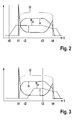
- FIGS. 2 and 3 is in each case a graph with the current waveform I, the voltage U and the speed curve n of the electric brake motor time-dependent shown for a Zuspannvorgang.
- the application process begins by applying an electrical voltage and energizing the brake motor when the circuit is closed.
- the voltage U and the engine speed n have reached their maximum.
- the phase between t2 and t3 represents the idle phase in which the current I moves to a minimum level.
- the force build-up phase from the time t3 to the time t4, in which the brake pads bear against the brake disc and are pressed with increasing clamping force F against the brake disc.
- the switching off of the electric brake motor takes place by opening the electric circuit, so that in the further course the speed n of the brake motor drops to zero.
- the force build-up or the course of the clamping force F can be determined, for example, based on the course of the current I of the brake motor, which basically has the same course as the electromechanical clamping force. Starting from the low level during the idle phase between t2 and t3, the current profile increases steeply at the beginning of time t3. This increase in current can be detected and used to determine the force rise point. In principle, however, the course of the force build-up can also be determined from the voltage or speed curve or from any combination of the signals current, voltage and rotational speed.
- a support pressure p U is shown, which is generated by the hydraulic brake device, in addition to the electromechanical clamping force to generate a hydraulic clamping force that adds to the total clamping force with the electromechanical clamping force.
- a hydraulic pressure is applied via the vehicle brake, which acts on the back of the brake piston and supports the electromechanical clamping force.
- the prepressure p before is considered in the hydraulic system, which is applied by the driver via a brake pedal operation at the time of delivery of the electric brake motor; the pre-pressure p Before is subtracted, because the support pressure only needs to generate the difference between the pre-pressure and the absolute pressure level to be reached.
- the cut- off pressure p t, off is the effective pressure on the brake piston at the time of switching off the electric brake motor, which corresponds directly to the hydraulic clamping force.
- ⁇ p represents a constant amount of pressure that characterizes the pressure drop that occurs in the hydraulic system due to the forward movement of the brake piston during delivery and the concomitant increase in volume.
- the pressure drop ⁇ p is regardless of the pressure level for the respective vehicle brake always constant and is for example in a range of values between 10 bar and 20 bar.
- the pressure tolerance p tol can be used to account for model and measurement inaccuracies.
- FIGS. 2 and 3 illustrated course of the support pressure p U also corresponds to the cut-off pressure p t, off .
- the support pressure p U already made before the activation of the electric brake motor.
- the support pressure p U increases already at a time t0, which is before the time t1, at which the application process starts in the electromechanical brake system.
- the support pressure p U is already reached at the time t1 and is maintained until the time t3 in which the power buildup in the electromechanical brake system takes place.
- the switch-off time - decreases the support pressure p U , which is due to the increase in volume due to the advancing movement of the brake piston.
- the pressure drop in the course of p U between the times t3 and t4 corresponds to the pressure amount ⁇ p.
- the assist pressure p U in the hydraulic brake device is generated only during the idling phase between the times t2 and t3.
- the build-up of pressure begins, which ends before the idling phase ends at the time t3 when the full assist pressure p U is reached.
- the power generation phase between the times t3 and t4 drops as at Fig. 2 the pressure level of the support pressure p U due to the increase in volume again.
- the cut-off pressure p t, off is reached.
Landscapes
- Engineering & Computer Science (AREA)
- Mechanical Engineering (AREA)
- Transportation (AREA)
- General Engineering & Computer Science (AREA)
- Braking Systems And Boosters (AREA)
- Braking Arrangements (AREA)
- Regulating Braking Force (AREA)
Applications Claiming Priority (2)
| Application Number | Priority Date | Filing Date | Title |
|---|---|---|---|
| DE201010063404 DE102010063404A1 (de) | 2010-12-17 | 2010-12-17 | Verfahren zum Einstellen der von einer Feststellbremse ausgeübten Klemmkraft |
| PCT/EP2011/071777 WO2012080025A1 (de) | 2010-12-17 | 2011-12-05 | Verfahren zum einstellen der von einer feststellbremse ausgeübten klemmkraft |
Publications (2)
| Publication Number | Publication Date |
|---|---|
| EP2651733A1 EP2651733A1 (de) | 2013-10-23 |
| EP2651733B1 true EP2651733B1 (de) | 2015-02-25 |
Family
ID=45217545
Family Applications (1)
| Application Number | Title | Priority Date | Filing Date |
|---|---|---|---|
| EP20110793413 Active EP2651733B1 (de) | 2010-12-17 | 2011-12-05 | Verfahren zum einstellen der von einer feststellbremse ausgeübten klemmkraft |
Country Status (7)
| Country | Link |
|---|---|
| US (1) | US9114792B2 (ja) |
| EP (1) | EP2651733B1 (ja) |
| JP (1) | JP5815177B2 (ja) |
| KR (1) | KR101941301B1 (ja) |
| CN (1) | CN103249620B (ja) |
| DE (1) | DE102010063404A1 (ja) |
| WO (1) | WO2012080025A1 (ja) |
Families Citing this family (11)
| Publication number | Priority date | Publication date | Assignee | Title |
|---|---|---|---|---|
| DE102009047127B4 (de) * | 2009-11-25 | 2023-07-27 | Robert Bosch Gmbh | Verfahren zum Betreiben einer Feststellbremse eines Fahrzeugs |
| DE102011077786A1 (de) * | 2011-06-20 | 2012-12-20 | Continental Teves Ag & Co. Ohg | Aktuatorsystem und Betriebsverfahren für ein Aktuatorsystem |
| DE102012205576A1 (de) * | 2012-04-04 | 2013-10-10 | Robert Bosch Gmbh | Verfahren zum Bereitstellen der von einer Feststellbremse erzeugten Klemmkraft |
| DE102014202178A1 (de) * | 2014-02-06 | 2015-08-06 | Robert Bosch Gmbh | Verfahren zum Betätigen einer automatischen Feststellbremse |
| DE102015206034A1 (de) * | 2015-04-02 | 2016-10-06 | Robert Bosch Gmbh | Verfahren und Vorrichtung zum Betreiben eines Bremssystems eines Fahrzeugs, Bremssystem |
| FR3044992B1 (fr) * | 2015-12-15 | 2019-05-31 | Foundation Brakes France | Procede de commande d'un systeme de freinage apte a realiser la fonction frein de parking |
| DE102016205298A1 (de) * | 2016-03-31 | 2017-10-05 | Robert Bosch Gmbh | Verfahren zum Bereitstellen einer Bremskraft in einem Fahrzeug |
| DE102016208396A1 (de) * | 2016-05-17 | 2017-11-23 | Robert Bosch Gmbh | Verfahren zum Überprüfen der Bremskraft in einem Fahrzeug |
| DE102016223826A1 (de) * | 2016-11-30 | 2018-05-30 | Robert Bosch Gmbh | Verfahren und Vorrichtung zum Betreiben eines hydraulischen Bremssystems, Bremssystem |
| DE102016223808A1 (de) * | 2016-11-30 | 2018-05-30 | Robert Bosch Gmbh | Verfahren und Vorrichtung zum Betreiben eines hydraulischen Bremssystems, Bremssystem |
| DE102018210021A1 (de) * | 2018-06-20 | 2019-12-24 | Robert Bosch Gmbh | Verfahren zum Betreiben eines Bremssystems eines Kraftfahrzeugs, sowie Steuergerät und Bremssystem |
Family Cites Families (13)
| Publication number | Priority date | Publication date | Assignee | Title |
|---|---|---|---|---|
| US6311808B1 (en) | 1996-02-09 | 2001-11-06 | Continental Teves Ag & Co., Ohg | Combined service and parking brake system |
| DE19611359C1 (de) * | 1996-03-22 | 1997-08-28 | Daimler Benz Ag | Verfahren zum Verhindern unbeabsichtigten Wegrollens eines Fahrzeugs |
| JP4058068B2 (ja) * | 1999-09-21 | 2008-03-05 | トヨタ自動車株式会社 | ブレーキ制御装置 |
| EP1154356A1 (en) * | 2000-05-09 | 2001-11-14 | Alcatel | Caching of files during loading from a distributed file system |
| JP4033281B2 (ja) * | 2000-09-06 | 2008-01-16 | 日産自動車株式会社 | 制動装置 |
| DE10345485B4 (de) * | 2003-09-30 | 2016-08-04 | Volkswagen Ag | Bremsvorrichtung mit Betriebs- und Feststellbremsfunktion |
| DE10351026B3 (de) * | 2003-10-31 | 2005-06-30 | Lucas Automotive Gmbh | Verfahren zum Stabilisieren eines in Stillstand abgebremsten Kraftfahrzeugs und Bremssystem zum Ausführen des Verfahrens |
| DE10361042B3 (de) | 2003-12-23 | 2005-05-25 | Lucas Automotive Gmbh | Feststellbremse und Verfahren zur Steuerung derselben |
| DE102004004992B4 (de) * | 2004-01-30 | 2008-03-13 | Lucas Automotive Gmbh | Verfahren zum Betreiben der Bremsausrüstung eines Fahrzeugs |
| JP4664749B2 (ja) * | 2005-06-28 | 2011-04-06 | 本田技研工業株式会社 | 車両用ブレーキ装置 |
| DE102008052847A1 (de) * | 2007-10-24 | 2009-05-07 | Continental Teves Ag & Co. Ohg | Feststellbremse und Verfahren zum Betrieb derselben |
| DE102008012338A1 (de) * | 2008-03-03 | 2009-09-10 | Lucas Automotive Gmbh | Technik zum Betätigen einer hydraulischen Feststellbremse |
| DE102010002825A1 (de) * | 2010-03-12 | 2011-09-15 | Robert Bosch Gmbh | Verfahren zum Einstellen der von einer Feststellbremse ausgeübten Klemmkraft |
-
2010
- 2010-12-17 DE DE201010063404 patent/DE102010063404A1/de not_active Withdrawn
-
2011
- 2011-12-05 CN CN201180060809.8A patent/CN103249620B/zh active Active
- 2011-12-05 EP EP20110793413 patent/EP2651733B1/de active Active
- 2011-12-05 JP JP2013543641A patent/JP5815177B2/ja active Active
- 2011-12-05 KR KR1020137015489A patent/KR101941301B1/ko active IP Right Grant
- 2011-12-05 WO PCT/EP2011/071777 patent/WO2012080025A1/de active Application Filing
- 2011-12-05 US US13/994,513 patent/US9114792B2/en active Active
Also Published As
| Publication number | Publication date |
|---|---|
| JP5815177B2 (ja) | 2015-11-17 |
| KR20130129981A (ko) | 2013-11-29 |
| US9114792B2 (en) | 2015-08-25 |
| KR101941301B1 (ko) | 2019-01-22 |
| JP2013545670A (ja) | 2013-12-26 |
| CN103249620B (zh) | 2016-06-22 |
| DE102010063404A1 (de) | 2012-06-21 |
| US20130333988A1 (en) | 2013-12-19 |
| EP2651733A1 (de) | 2013-10-23 |
| CN103249620A (zh) | 2013-08-14 |
| WO2012080025A1 (de) | 2012-06-21 |
Similar Documents
| Publication | Publication Date | Title |
|---|---|---|
| EP2651733B1 (de) | Verfahren zum einstellen der von einer feststellbremse ausgeübten klemmkraft | |
| EP2651723B1 (de) | Verfahren zum einstellen der von einer feststellbremse ausgeübten stellkraft | |
| EP2504599B1 (de) | Verfahren zum betreiben einer feststellbremse eines fahrzeugs | |
| DE102011083305B4 (de) | Elektrischer Bremsverstärker | |
| EP1708912B1 (de) | Verfahren zum betreiben der bremsausrüstung eines fahrzeugs | |
| EP2651732B1 (de) | Verfahren zum einstellen der von einer feststellbremse ausgeübten klemmkraft | |
| EP3204660B1 (de) | Bremsvorrichtung für ein kraftfahrzeug und verfahren zur ansteuerung der bremsvorrichtung bei einer überlagerung verschiedener kraftkomponenten | |
| EP3297877B1 (de) | Verfahren zum bereitstellen einer bremskraft in einem fahrzeug | |
| DE102011004786A1 (de) | Verfahren zum Einstellen der von einer Feststellbremse ausgeübten Klemmkraft in einem Fahrzeug | |
| EP2651720B1 (de) | Verfahren zum einstellen der von einer feststellbremse ausgeübten klemmkraft | |
| DE102011101062A1 (de) | Technik zum Ermitteln einer an einer hydraulisch und mechanisch betätigbaren Fahrzeugbremse anliegenden Betätigungskraft | |
| DE102016213645A1 (de) | Verfahren zum Betreiben einer automatisierten Feststellbremse | |
| EP2688778B1 (de) | Verfahren zum einstellen einer feststellbremse in einem fahrzeug | |
| DE102011004772A1 (de) | Verfahren zum Einstellen der von einer Feststellbremse ausgeübten Klemmkraft | |
| DE102015210431A1 (de) | Verfahren zum Ansteuern einer Feststellbremse in einem Fahrzeug | |
| DE102015210433A1 (de) | Verfahren zum Abbremsen eines Fahrzeugs | |
| DE102015211461A1 (de) | Verfahren zum Überprüfen der Bremskraft in einem Fahrzeug | |
| DE102016213666A1 (de) | Verfahren zum Betreiben einer automatisierten Feststellbremse | |
| DE102016222045A1 (de) | Verfahren und Vorrichtung zum Betreiben einer Bremsanlage eines Kraftfahrzeugs, Bremsanlage | |
| DE102016214195A1 (de) | Verfahren zur Funktionsprüfung einer elektromechanischen Bremsvorrichtung | |
| EP3585663B1 (de) | Bremssystem für ein fahrzeug mit einer hydraulischen fahrzeugbremse und mit einer elektromechanischen bremsvorrichtung | |
| EP3458320B1 (de) | Verfahren zum überprüfen der bremskraft in einem fahrzeug | |
| EP4003796B1 (de) | Verfahren zum ansteuern eines hydraulischen bremssystems in einem fahrzeug | |
| EP3468848A1 (de) | Verfahren zum betreiben einer elektromechanischen bremsvorrichtung | |
| WO2012079803A2 (de) | Verfahren zum einstellen der von einer feststellbremse ausgeübten klemmkraft |
Legal Events
| Date | Code | Title | Description |
|---|---|---|---|
| PUAI | Public reference made under article 153(3) epc to a published international application that has entered the european phase |
Free format text: ORIGINAL CODE: 0009012 |
|
| 17P | Request for examination filed |
Effective date: 20130717 |
|
| AK | Designated contracting states |
Kind code of ref document: A1 Designated state(s): AL AT BE BG CH CY CZ DE DK EE ES FI FR GB GR HR HU IE IS IT LI LT LU LV MC MK MT NL NO PL PT RO RS SE SI SK SM TR |
|
| DAX | Request for extension of the european patent (deleted) | ||
| GRAP | Despatch of communication of intention to grant a patent |
Free format text: ORIGINAL CODE: EPIDOSNIGR1 |
|
| INTG | Intention to grant announced |
Effective date: 20141107 |
|
| GRAS | Grant fee paid |
Free format text: ORIGINAL CODE: EPIDOSNIGR3 |
|
| GRAA | (expected) grant |
Free format text: ORIGINAL CODE: 0009210 |
|
| AK | Designated contracting states |
Kind code of ref document: B1 Designated state(s): AL AT BE BG CH CY CZ DE DK EE ES FI FR GB GR HR HU IE IS IT LI LT LU LV MC MK MT NL NO PL PT RO RS SE SI SK SM TR |
|
| REG | Reference to a national code |
Ref country code: GB Ref legal event code: FG4D Free format text: NOT ENGLISH |
|
| REG | Reference to a national code |
Ref country code: CH Ref legal event code: EP |
|
| REG | Reference to a national code |
Ref country code: IE Ref legal event code: FG4D Free format text: LANGUAGE OF EP DOCUMENT: GERMAN |
|
| REG | Reference to a national code |
Ref country code: DE Ref legal event code: R096 Ref document number: 502011006039 Country of ref document: DE Effective date: 20150409 |
|
| REG | Reference to a national code |
Ref country code: AT Ref legal event code: REF Ref document number: 711674 Country of ref document: AT Kind code of ref document: T Effective date: 20150415 |
|
| REG | Reference to a national code |
Ref country code: NL Ref legal event code: VDEP Effective date: 20150225 |
|
| REG | Reference to a national code |
Ref country code: LT Ref legal event code: MG4D |
|
| PG25 | Lapsed in a contracting state [announced via postgrant information from national office to epo] |
Ref country code: SE Free format text: LAPSE BECAUSE OF FAILURE TO SUBMIT A TRANSLATION OF THE DESCRIPTION OR TO PAY THE FEE WITHIN THE PRESCRIBED TIME-LIMIT Effective date: 20150225 Ref country code: ES Free format text: LAPSE BECAUSE OF FAILURE TO SUBMIT A TRANSLATION OF THE DESCRIPTION OR TO PAY THE FEE WITHIN THE PRESCRIBED TIME-LIMIT Effective date: 20150225 Ref country code: NO Free format text: LAPSE BECAUSE OF FAILURE TO SUBMIT A TRANSLATION OF THE DESCRIPTION OR TO PAY THE FEE WITHIN THE PRESCRIBED TIME-LIMIT Effective date: 20150525 Ref country code: HR Free format text: LAPSE BECAUSE OF FAILURE TO SUBMIT A TRANSLATION OF THE DESCRIPTION OR TO PAY THE FEE WITHIN THE PRESCRIBED TIME-LIMIT Effective date: 20150225 Ref country code: FI Free format text: LAPSE BECAUSE OF FAILURE TO SUBMIT A TRANSLATION OF THE DESCRIPTION OR TO PAY THE FEE WITHIN THE PRESCRIBED TIME-LIMIT Effective date: 20150225 Ref country code: LT Free format text: LAPSE BECAUSE OF FAILURE TO SUBMIT A TRANSLATION OF THE DESCRIPTION OR TO PAY THE FEE WITHIN THE PRESCRIBED TIME-LIMIT Effective date: 20150225 |
|
| PG25 | Lapsed in a contracting state [announced via postgrant information from national office to epo] |
Ref country code: GR Free format text: LAPSE BECAUSE OF FAILURE TO SUBMIT A TRANSLATION OF THE DESCRIPTION OR TO PAY THE FEE WITHIN THE PRESCRIBED TIME-LIMIT Effective date: 20150526 Ref country code: RS Free format text: LAPSE BECAUSE OF FAILURE TO SUBMIT A TRANSLATION OF THE DESCRIPTION OR TO PAY THE FEE WITHIN THE PRESCRIBED TIME-LIMIT Effective date: 20150225 Ref country code: LV Free format text: LAPSE BECAUSE OF FAILURE TO SUBMIT A TRANSLATION OF THE DESCRIPTION OR TO PAY THE FEE WITHIN THE PRESCRIBED TIME-LIMIT Effective date: 20150225 Ref country code: IS Free format text: LAPSE BECAUSE OF FAILURE TO SUBMIT A TRANSLATION OF THE DESCRIPTION OR TO PAY THE FEE WITHIN THE PRESCRIBED TIME-LIMIT Effective date: 20150625 |
|
| PG25 | Lapsed in a contracting state [announced via postgrant information from national office to epo] |
Ref country code: NL Free format text: LAPSE BECAUSE OF FAILURE TO SUBMIT A TRANSLATION OF THE DESCRIPTION OR TO PAY THE FEE WITHIN THE PRESCRIBED TIME-LIMIT Effective date: 20150225 |
|
| PG25 | Lapsed in a contracting state [announced via postgrant information from national office to epo] |
Ref country code: SK Free format text: LAPSE BECAUSE OF FAILURE TO SUBMIT A TRANSLATION OF THE DESCRIPTION OR TO PAY THE FEE WITHIN THE PRESCRIBED TIME-LIMIT Effective date: 20150225 Ref country code: RO Free format text: LAPSE BECAUSE OF FAILURE TO SUBMIT A TRANSLATION OF THE DESCRIPTION OR TO PAY THE FEE WITHIN THE PRESCRIBED TIME-LIMIT Effective date: 20150225 Ref country code: CZ Free format text: LAPSE BECAUSE OF FAILURE TO SUBMIT A TRANSLATION OF THE DESCRIPTION OR TO PAY THE FEE WITHIN THE PRESCRIBED TIME-LIMIT Effective date: 20150225 Ref country code: DK Free format text: LAPSE BECAUSE OF FAILURE TO SUBMIT A TRANSLATION OF THE DESCRIPTION OR TO PAY THE FEE WITHIN THE PRESCRIBED TIME-LIMIT Effective date: 20150225 Ref country code: EE Free format text: LAPSE BECAUSE OF FAILURE TO SUBMIT A TRANSLATION OF THE DESCRIPTION OR TO PAY THE FEE WITHIN THE PRESCRIBED TIME-LIMIT Effective date: 20150225 |
|
| REG | Reference to a national code |
Ref country code: DE Ref legal event code: R097 Ref document number: 502011006039 Country of ref document: DE |
|
| PG25 | Lapsed in a contracting state [announced via postgrant information from national office to epo] |
Ref country code: PL Free format text: LAPSE BECAUSE OF FAILURE TO SUBMIT A TRANSLATION OF THE DESCRIPTION OR TO PAY THE FEE WITHIN THE PRESCRIBED TIME-LIMIT Effective date: 20150225 |
|
| REG | Reference to a national code |
Ref country code: FR Ref legal event code: PLFP Year of fee payment: 5 |
|
| PG25 | Lapsed in a contracting state [announced via postgrant information from national office to epo] |
Ref country code: IT Free format text: LAPSE BECAUSE OF FAILURE TO SUBMIT A TRANSLATION OF THE DESCRIPTION OR TO PAY THE FEE WITHIN THE PRESCRIBED TIME-LIMIT Effective date: 20150225 |
|
| PLBE | No opposition filed within time limit |
Free format text: ORIGINAL CODE: 0009261 |
|
| STAA | Information on the status of an ep patent application or granted ep patent |
Free format text: STATUS: NO OPPOSITION FILED WITHIN TIME LIMIT |
|
| 26N | No opposition filed |
Effective date: 20151126 |
|
| PG25 | Lapsed in a contracting state [announced via postgrant information from national office to epo] |
Ref country code: SI Free format text: LAPSE BECAUSE OF FAILURE TO SUBMIT A TRANSLATION OF THE DESCRIPTION OR TO PAY THE FEE WITHIN THE PRESCRIBED TIME-LIMIT Effective date: 20150225 |
|
| PG25 | Lapsed in a contracting state [announced via postgrant information from national office to epo] |
Ref country code: BE Free format text: LAPSE BECAUSE OF NON-PAYMENT OF DUE FEES Effective date: 20151231 |
|
| PG25 | Lapsed in a contracting state [announced via postgrant information from national office to epo] |
Ref country code: MC Free format text: LAPSE BECAUSE OF FAILURE TO SUBMIT A TRANSLATION OF THE DESCRIPTION OR TO PAY THE FEE WITHIN THE PRESCRIBED TIME-LIMIT Effective date: 20150225 Ref country code: LU Free format text: LAPSE BECAUSE OF FAILURE TO SUBMIT A TRANSLATION OF THE DESCRIPTION OR TO PAY THE FEE WITHIN THE PRESCRIBED TIME-LIMIT Effective date: 20151205 |
|
| REG | Reference to a national code |
Ref country code: CH Ref legal event code: PL |
|
| REG | Reference to a national code |
Ref country code: IE Ref legal event code: MM4A |
|
| PG25 | Lapsed in a contracting state [announced via postgrant information from national office to epo] |
Ref country code: CH Free format text: LAPSE BECAUSE OF NON-PAYMENT OF DUE FEES Effective date: 20151231 Ref country code: IE Free format text: LAPSE BECAUSE OF NON-PAYMENT OF DUE FEES Effective date: 20151205 Ref country code: LI Free format text: LAPSE BECAUSE OF NON-PAYMENT OF DUE FEES Effective date: 20151231 |
|
| REG | Reference to a national code |
Ref country code: FR Ref legal event code: PLFP Year of fee payment: 6 |
|
| PG25 | Lapsed in a contracting state [announced via postgrant information from national office to epo] |
Ref country code: BG Free format text: LAPSE BECAUSE OF FAILURE TO SUBMIT A TRANSLATION OF THE DESCRIPTION OR TO PAY THE FEE WITHIN THE PRESCRIBED TIME-LIMIT Effective date: 20150225 Ref country code: SM Free format text: LAPSE BECAUSE OF FAILURE TO SUBMIT A TRANSLATION OF THE DESCRIPTION OR TO PAY THE FEE WITHIN THE PRESCRIBED TIME-LIMIT Effective date: 20150225 Ref country code: HU Free format text: LAPSE BECAUSE OF FAILURE TO SUBMIT A TRANSLATION OF THE DESCRIPTION OR TO PAY THE FEE WITHIN THE PRESCRIBED TIME-LIMIT; INVALID AB INITIO Effective date: 20111205 |
|
| PG25 | Lapsed in a contracting state [announced via postgrant information from national office to epo] |
Ref country code: CY Free format text: LAPSE BECAUSE OF FAILURE TO SUBMIT A TRANSLATION OF THE DESCRIPTION OR TO PAY THE FEE WITHIN THE PRESCRIBED TIME-LIMIT Effective date: 20150225 |
|
| PG25 | Lapsed in a contracting state [announced via postgrant information from national office to epo] |
Ref country code: MT Free format text: LAPSE BECAUSE OF FAILURE TO SUBMIT A TRANSLATION OF THE DESCRIPTION OR TO PAY THE FEE WITHIN THE PRESCRIBED TIME-LIMIT Effective date: 20150225 |
|
| REG | Reference to a national code |
Ref country code: FR Ref legal event code: PLFP Year of fee payment: 7 |
|
| REG | Reference to a national code |
Ref country code: AT Ref legal event code: MM01 Ref document number: 711674 Country of ref document: AT Kind code of ref document: T Effective date: 20161205 |
|
| PG25 | Lapsed in a contracting state [announced via postgrant information from national office to epo] |
Ref country code: AT Free format text: LAPSE BECAUSE OF NON-PAYMENT OF DUE FEES Effective date: 20161205 |
|
| PG25 | Lapsed in a contracting state [announced via postgrant information from national office to epo] |
Ref country code: PT Free format text: LAPSE BECAUSE OF FAILURE TO SUBMIT A TRANSLATION OF THE DESCRIPTION OR TO PAY THE FEE WITHIN THE PRESCRIBED TIME-LIMIT Effective date: 20150225 Ref country code: TR Free format text: LAPSE BECAUSE OF FAILURE TO SUBMIT A TRANSLATION OF THE DESCRIPTION OR TO PAY THE FEE WITHIN THE PRESCRIBED TIME-LIMIT Effective date: 20150225 Ref country code: MK Free format text: LAPSE BECAUSE OF FAILURE TO SUBMIT A TRANSLATION OF THE DESCRIPTION OR TO PAY THE FEE WITHIN THE PRESCRIBED TIME-LIMIT Effective date: 20150225 |
|
| PG25 | Lapsed in a contracting state [announced via postgrant information from national office to epo] |
Ref country code: AL Free format text: LAPSE BECAUSE OF FAILURE TO SUBMIT A TRANSLATION OF THE DESCRIPTION OR TO PAY THE FEE WITHIN THE PRESCRIBED TIME-LIMIT Effective date: 20150225 |
|
| PGFP | Annual fee paid to national office [announced via postgrant information from national office to epo] |
Ref country code: GB Payment date: 20231220 Year of fee payment: 13 |
|
| PGFP | Annual fee paid to national office [announced via postgrant information from national office to epo] |
Ref country code: FR Payment date: 20231219 Year of fee payment: 13 |
|
| PGFP | Annual fee paid to national office [announced via postgrant information from national office to epo] |
Ref country code: DE Payment date: 20240227 Year of fee payment: 13 |