EP2649246B1 - Sanitary system with a central mixing facility - Google Patents
Sanitary system with a central mixing facility Download PDFInfo
- Publication number
- EP2649246B1 EP2649246B1 EP11794003.1A EP11794003A EP2649246B1 EP 2649246 B1 EP2649246 B1 EP 2649246B1 EP 11794003 A EP11794003 A EP 11794003A EP 2649246 B1 EP2649246 B1 EP 2649246B1
- Authority
- EP
- European Patent Office
- Prior art keywords
- water
- mixing
- consumer
- sanitary system
- temperature
- Prior art date
- Legal status (The legal status is an assumption and is not a legal conclusion. Google has not performed a legal analysis and makes no representation as to the accuracy of the status listed.)
- Active
Links
- 238000002156 mixing Methods 0.000 title claims description 77
- XLYOFNOQVPJJNP-UHFFFAOYSA-N water Substances O XLYOFNOQVPJJNP-UHFFFAOYSA-N 0.000 claims description 238
- 238000011084 recovery Methods 0.000 claims description 17
- 238000004891 communication Methods 0.000 claims description 16
- 230000005540 biological transmission Effects 0.000 claims description 6
- 238000011156 evaluation Methods 0.000 claims description 4
- 238000005259 measurement Methods 0.000 claims 2
- 238000009434 installation Methods 0.000 description 16
- 238000005406 washing Methods 0.000 description 8
- 230000008901 benefit Effects 0.000 description 6
- 230000001276 controlling effect Effects 0.000 description 4
- 239000000203 mixture Substances 0.000 description 4
- 239000012530 fluid Substances 0.000 description 3
- 230000006978 adaptation Effects 0.000 description 2
- 230000004888 barrier function Effects 0.000 description 2
- 238000004140 cleaning Methods 0.000 description 2
- 238000011010 flushing procedure Methods 0.000 description 2
- 230000006870 function Effects 0.000 description 2
- 238000000034 method Methods 0.000 description 2
- 230000008569 process Effects 0.000 description 2
- 238000012546 transfer Methods 0.000 description 2
- 235000008733 Citrus aurantifolia Nutrition 0.000 description 1
- 241000589248 Legionella Species 0.000 description 1
- 208000007764 Legionnaires' Disease Diseases 0.000 description 1
- 206010053615 Thermal burn Diseases 0.000 description 1
- 235000011941 Tilia x europaea Nutrition 0.000 description 1
- 230000002411 adverse Effects 0.000 description 1
- 230000008859 change Effects 0.000 description 1
- 239000003795 chemical substances by application Substances 0.000 description 1
- 238000013461 design Methods 0.000 description 1
- 238000005265 energy consumption Methods 0.000 description 1
- 239000004571 lime Substances 0.000 description 1
- 239000007788 liquid Substances 0.000 description 1
- 238000012423 maintenance Methods 0.000 description 1
- 230000003287 optical effect Effects 0.000 description 1
- 230000001681 protective effect Effects 0.000 description 1
- 230000009467 reduction Effects 0.000 description 1
- 230000001105 regulatory effect Effects 0.000 description 1
- 238000005070 sampling Methods 0.000 description 1
- 230000008054 signal transmission Effects 0.000 description 1
- 239000007921 spray Substances 0.000 description 1
- 239000008400 supply water Substances 0.000 description 1
- 238000003809 water extraction Methods 0.000 description 1
Images


Classifications
-
- E—FIXED CONSTRUCTIONS
- E03—WATER SUPPLY; SEWERAGE
- E03B—INSTALLATIONS OR METHODS FOR OBTAINING, COLLECTING, OR DISTRIBUTING WATER
- E03B1/00—Methods or layout of installations for water supply
- E03B1/04—Methods or layout of installations for water supply for domestic or like local supply
- E03B1/048—Systems for collecting not used fresh water
-
- E—FIXED CONSTRUCTIONS
- E03—WATER SUPPLY; SEWERAGE
- E03B—INSTALLATIONS OR METHODS FOR OBTAINING, COLLECTING, OR DISTRIBUTING WATER
- E03B1/00—Methods or layout of installations for water supply
- E03B1/04—Methods or layout of installations for water supply for domestic or like local supply
-
- E—FIXED CONSTRUCTIONS
- E03—WATER SUPPLY; SEWERAGE
- E03C—DOMESTIC PLUMBING INSTALLATIONS FOR FRESH WATER OR WASTE WATER; SINKS
- E03C1/00—Domestic plumbing installations for fresh water or waste water; Sinks
- E03C1/02—Plumbing installations for fresh water
- E03C1/05—Arrangements of devices on wash-basins, baths, sinks, or the like for remote control of taps
-
- G—PHYSICS
- G05—CONTROLLING; REGULATING
- G05D—SYSTEMS FOR CONTROLLING OR REGULATING NON-ELECTRIC VARIABLES
- G05D23/00—Control of temperature
Definitions
- the invention relates to a sanitary system with a mixing center according to the preamble of claim 1, as is known from the document WO85 / 03764 is known.
- Sanitary systems in houses and apartments provide service water especially for sinks, bathtubs, showers, toilets, washing machines, kitchen sinks or dishwashers.
- a hot water pipe and a cold water pipe are routed to the consumer and installed at the consumer mixing devices to receive hot water of a certain temperature and a certain flow rate, ie in particular sinks, baths, showers and kitchen sinks. If only a cold water supply is required, ie especially in toilets, washing machines or dishwashers, only a cold water pipe is laid to the consumer.
- the CH 698 596 shows a sanitary house installation with a distribution block, which contains a cold water pipe and a hot water pipe and is connected to a cold water pipe and a hot water pipe.
- a large number of dosing devices can be coupled to the distribution block and contain adjusting agents for the flow.
- Per metering leads a single line to a sampling point with an operating element, which are transmitted via an information channel operator actions to a control unit for generating control information for the actuating means.
- the EP 0 195 271 shows a sanitary device to provide in a bathroom several washing facilities with hot and cold water.
- a central unit includes a cold and hot water connection and several outlets to supply the washing facilities with water. Temperature and volume are adjusted for each outlet by a mixing valve.
- a thermoscopic unit keeps the temperature substantially at the predetermined value.
- a temperature sensor is connected to a control unit. Adjustments and a main controller are connected to the center.
- the control panel can have a flow or pressure regulator for individual regulation for each individual fitting attached to the control unit. All functions (volume, temperature, flow) are controlled by the central control unit, but the user still has temperature and on / off status can change.
- the programmatic automated operation of the control system allows certain safety aspects to be considered.
- the DE 101 19 690 concerns a sanitary installation in a bathroom.
- the bathroom has several, spatially spaced sanitary facilities such as a bathtub, a shower, a hand basin, a bidet and the like.
- a central mixing valve has inlet connections for cold and hot water and several mixed water outlets. The mixed water outlets are each connected to a water inlet of a sanitary facility.
- the sanitary device comprises a temperature measuring device and a flow measuring device.
- An electronic control controls and monitors all mixed water flows. Default values for the mixed water temperature or flow rate can be entered and saved.
- An input / output device comprises keys as well as a display and can be arranged decentrally on sanitary facilities.
- the WO 03/107527 shows a sanitary installation for the supply of residential units with cold and hot water.
- a central distributor fitting has a cold and hot water connection and a mixed water outlet connection.
- a single pipe is passed through the entire residential unit and has taps.
- the tap has a remote control part.
- the object of the invention is to provide a sanitary system belonging to the technical field mentioned above, which requires little installation effort and allows flexible adaptations to different requirements.
- a consumer identification relating to the consumer is the Control center transferable, which takes into account the control center for controlling the controllable mixing unit.
- the transmission of consumer identification is via any communication channel, i. H. via a communication cable such as a signal line, via a bus system, via a wireless communication link such. A WiFi network or any other communication channel.
- a communication cable such as a signal line
- a bus system via a wireless communication link such.
- an electronic memory is provided for storing the consumer identification, ie z.
- the control center has a corresponding communication module which is connected to the consumer-mounted communication module, ie z. B. via a serial communication cable. After setting a parameter value on the operating device, this is transmitted to the control center, which immediately performs a query concerning the consumer identification via the mentioned communication means.
- a consumer identification can also z. B.
- a consumer identification may also be entered directly at the control center, for example via a keyboard, which is connected to the control center during commissioning of the sanitary system in order to carry out a configuration of the system.
- a list of possible or permitted consumers is stored in a data memory of the control center.
- the control center can control the valves or mixers belonging to the fluid line to which the consumer is connected.
- Means are also provided to link the consumer identification with a mixing line.
- the identification of the mixed line results from the identification of the relevant cable or the relevant bus subscriber.
- an identification can be attached to the consumer side of the mixing line, which together with the Consumer identification is transmitted.
- the consumer side attached to the mixing line identification can be visually or electronically detected, so z. B. consist of a license plate or an electronic storage device such as an RFID chip.
- the control center is set up, for example, that from the consumer identification of the consumer type can be determined, so that it can be determined whether it is a shower, a sink, a bath or a toilet.
- the maximum temperature of the water can be limited to avoid scalding the user.
- the water pressure can be limited to prevent splashing of water, which meets with too high pressure on the sink.
- the mixing center has several mixing pipes on the output side and is equipped to supply, for example, all the sanitary facilities of a bathroom or kitchen with water.
- a mixing line for the sink, a mixing pipe for the shower, a mixing pipe for the bath and a mixing pipe for the toilet may be provided.
- the mixing center can directly in a room, so z. B. in the bathroom, be arranged. But it is also possible, the mixing center z. B. in the basement or another adjoining room to install.
- a mixing unit may include a temperature mixer and a flow regulator.
- the temperature mixer is connected on the input side to the hot water pipe and the cold water pipe and provides on the output side a certain mixing ratio between hot water and cold water. With the flow regulator then the amount of water is set, which is delivered to the mixing line.
- the mixing unit can also have metering devices for the hot water and the cold water, wherein a metered amount of hot water and cold water amount is combined and delivered to the mixing line (such as in the CH 698 596 described).
- the consumer identification can be transmitted to the control center regularly, at certain times or due to certain events. Thus, for example, in a dishwasher or in a washing machine, the consumer identification can be queried regularly to adjust the currently required hot water settings regarding temperature or pressure.
- the consumer identification is not equivalent to a control command, which the control center z. B. indicating which amount of water, which pressure, which temperature, etc. is to be delivered to the consumer at a certain time.
- the consumer identification can also be transmitted as part of a washing program together with the consumer commands (which temperature, amount, pressure, etc. specify) to the control center to request required settings of the service water. Instead of a regular polling of the consumer identification parameters relating to required dhw settings can be transmitted separately or queried.
- sensors are provided for determining measured values, in particular the temperature, the pressure and / or the flow rate, which the control center takes into account for controlling and / or regulating the controllable mixing unit.
- the sensors are arranged on the output side of the mixing lines, for example. Sensors can also be arranged on the input side of the hot water pipe and / or on the cold water pipe.
- the control center can be set up to either only control the controllable mixing unit, ie a certain mixing ratio and to set a certain flow rate or pressure. However, the control center can also be set up to take into account the measured values of the sensors in order to regulate the controllable mixing unit accordingly if the temperature or the pressure deviates.
- the measured values determined by the sensors can be transmitted to the operating device in order to display them to the user.
- the consumer has a clip-on fitting with a consumer identification that can be transmitted to the control center.
- the attachable fitting makes when plugging at the same time a water connection and electrical connections ago, so an electrical signal connection and / or a connection for electrical energy transfer.
- a connection is z. B. from the US 6,006,784 known.
- the clip-on valve can be designed as described in the application filed simultaneously with the present application "fitting base and attachable fitting" of the same applicant.
- the fitting may be arranged, for example, that first the water connection is created and only then electrical connections. This can ensure that a water release only takes place when the water connection is established.
- the control center and / or the fitting can be set up so that the consumer identification is transmitted to the control center as soon as the electrical connection to the fitting has been established.
- the consumer identification example in a consumer without attachable fitting, so z. B. in a toilet, a dishwasher or a washing machine, the consumer identification example, directly, ie entered via a keyboard connected to the control unit or via an interface to a portable computer at the control center.
- a consumer identification with the operating device can be generated and transferred to the control center. This is particularly advantageous for consumers without stored consumer identification, as may be the case for example in a toilet.
- the input of the consumer identification can be done via any provided on the operating device input means, so for example via a Keyboard, a touch screen, a reading device such as an optical scanner, an RFID reader, or any other input means.
- Cable-based, bus system-based and / or radio-based connections are preferably provided for signal and / or energy transmission. Cable-based or bus-based connections require additional installation effort, but allow energy transfer and high operational reliability. In contrast, require radio-based connections such. B. in a WiFi wireless network a smaller installation cost. However, to provide electrical energy, batteries are required or additional cable connections. A radio-based connection tends to be more susceptible to interference than a cable-based solution. A wired connection is also known as a wired connection.
- the control center takes into account a maximum and / or minimum value, for example a maximum water temperature, a maximum amount of water and / or a minimum water pressure, based on an evaluation of a consumer identification.
- a maximum and / or minimum value for example a maximum water temperature, a maximum amount of water and / or a minimum water pressure.
- the evaluation of the consumer identification can refer, for example, to a table and / or database query.
- the control center has a table for assigning consumer identifications to permissible operating values of a consumer. Due to the table, an assignment can be carried out quickly and efficiently.
- the table may have different entries for the same type of consumer so that, for example, for a clip-on fitting with an outlet far from the washbasin, a different operating value such as a water pressure is adjustable than for a clip-on fitting with an outlet very close to Sink is.
- the operating values are included in the consumer identification, ie digitally coded or as an electronic data sequence. This requires more effort concerning the storage means at the fitting and the communication means for transmitting the consumer identification.
- the mixing center has a plurality of mixing units, preferably between three and eight mixing units, which can be arranged in a modular design. With such a mixing center typical sanitary installation units such as a bathroom, a kitchen, a toilet can be completely supplied with service water.
- a module can be provided for connection to the hot and cold water line to which a desired number of identical modules can be connected, each with a mixing unit, d. H. a first module creates the connection to the hot and cold water line and it is quasi connected in a serial way a second, third, etc. module, each with a mixing unit.
- a mixing unit preferably has a temperature mixer for establishing a mixing ratio of hot and cold water and a quantity regulator connected thereto.
- the creation of the temperature of the service water and the adjustment of the pressure, the amount or flow rate is performed by two optimized for each task devices and is therefore precisely and easily controlled.
- the mixing unit each has a metering device for the hot and the cold water.
- setting the water temperature and / or pressure may be more complicated.
- a temperature sensor, a pressure sensor and / or a flow sensor are then provided downstream of a mixing unit.
- the readings from the sensors are transmitted to the control panel, allowing very precise control of parameters such as water temperature or pressure.
- a pressure reducing valve for the hot water pipe and / or a pressure reducing valve for the cold water pipe is provided.
- a corresponding hot and / or cold water pressure can thus be made available. So a short-term increased pressure requirements, such as in a toilet flush or in the cleaning of a shower can be satisfied. If the mixing center has a lot of mixed lines, which at the same time can be used, the corresponding water demand can be provided by opening the pressure reducing valves.
- a temperature sensor, a pressure sensor and / or a flow sensor is provided for the hot water line and / or for the cold water line.
- the measured values of these sensors can be transmitted to the control unit and taken into account for setting the mixing units. If, for example, the supplied hot water loses temperature, the mixing unit can be readjusted quickly and precisely.
- a sanitary system which includes recovery for recovering water and / or heat energy.
- the recovery is essentially formed by means of water pipes and valves, wherein the valves are preferably actuated by a control circuit and a motor.
- a control circuit and a motor With the help of such a recovery, it is typically possible, for example, at the beginning of a showering not yet tempered water via a return line back to a hot water circulation line, especially without the water leaves the sanitary system.
- This has the advantage on the one hand that water is saved, and on the other hand, that the heat energy of the returning in the return line water can be used. In this way it is typically possible to reduce the water and energy consumption of the sanitary system.
- the recovery is also applicable to other (liquid or gaseous) media instead of water.
- the recovery includes a 3/2 way valve.
- the 3/2 way valve is preferably connected on the input side with a mixing line of the sanitary system, via which the 3/2 way valve tempered mixed water is supplied.
- the 3/2 way valve is on the output side with a consumer, such as a shower head, a faucet or the like, and connected to the return line.
- the 3/2 way valve is typically suitable, depending on the temperature of the temperature-controlled mixing water supplied on the input side be forwarded.
- the recovery comprises a return collection.
- a return collection is advantageously suitable to combine a plurality of return lines or to collect returning water from a plurality of return lines and then preferably supplied controlled the hot water circulation line the water collected.
- Such a return collection has the advantage that a total line length in the sanitary system can be reduced.
- the recovery comprises a temperature sensor for controlling the 3/2 way valve.
- the temperature sensor comprises a bus connection for connecting the temperature sensor to a bus of the sanitary system.
- the temperature sensor is typically arranged on the input side at the 3/2 way valve. This configuration has the advantage that a particularly precise control of the 3/2-way valve is made possible, and that information of the temperature sensor via the bus connection at different points of the sanitary system is simple and essentially in real time retrievable and / or processable.
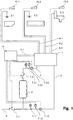
- Fig. 1 schematically shows a sanitary system according to the invention.
- a mixing center 1 is connected on the input side to a hot water pipe 2 and to a cold water pipe 3.
- the mixing center 1 is associated with a sanitary room such as a toilet room, a shower room, a bathroom, a kitchen, a laundry room or any other sanitary room.
- the mixing center 1 can also be assigned to an apartment, a floor or any other area of the house.
- the mixing center 1 has a plurality of mixing lines 4.1, 4.2, 4.3, the number of which is typically between three and eight as needed. However, any number of mixing lines 4.1, 4.2, 4.3 can be provided.
- the mixing lines 4.1, 4.2, 4.3 are set up to supply water to the decentralized consumers 5.1, 5.2, 5.3.
- the decentralized consumers 5.1, 5.2, 5.3 may concern a fitting of a washbasin, a bathtub, a shower, a toilet, a dishwasher, a washing machine, or any other sanitary consumer.
- Fig. 1 is with the reference numeral 5.1 a lavabo, with the Reference number 5.2 a bathtub and the reference number 5.3 a WC sketched schematically.
- the mixing lines 4.1, 4.2, 4.3 lead, as will be explained below, water according to desired parameters such as in particular a certain temperature, a certain pressure, a certain flow rate or any other parameter.
- a boiler 6 On the input side of the mixing device 1, a boiler 6 is provided for generating hot water, which is connected on the input side to the cold water pipe 3 and the output side water of a certain temperature leads to the mixing device 1.
- valves 7.1, 7.2 provided to adjust the supply of cold water from the supply line 8 to the boiler 6 and the cold water pipe 3 and the supply of hot water to the hot water pipe 2.
- pressure sensors 7.11, 7.12, temperature sensors 7.21, 7.22 and flow sensors 7.13, 7.23 are arranged, with which the temperature, pressure and flow rate can be measured.
- the inventive sanitary system further comprises a control center 9, which includes, for example, a microprocessor with software modules executable thereon.
- the control center 9 has inputs for the signals from sensors such. B. for the pressure sensors 7.11, 7.12, the temperature sensors 7.21, 7.22 and the flow sensors 7.13, 7.23.
- the control unit 9 also has outputs for control signals, such. B. for the valves 7.1.7.2.
- the control center 9 is signal-connected to the mixing center 1, for example via a bus system.
- control devices 10.1, 10.2, 10.3 are provided, which are also signal-wise connected to the mixing center 1.
- the operating devices 10.1, 10.2. 10.3 have input and output devices to select desired parameters such as a water temperature, an amount of water, a water pressure, a water velocity, or any other parameter to enter and / or display.
- the operating devices 10.1, 10.2, 10.3, for example, buttons, switches, electronic displays, a touch screen or any other means.
- the control devices 10.1, 10.2, 10.3 can be as practical as possible attached to a fitting of a sink, a bathtub, on a wall at a toilet bowl or any other location.
- Fig. 2 schematically shows an inventive mixing center 1.
- the mixing device On the input side, the mixing device is connected to a hot water pipe 2 and to a cold water pipe 3.
- a plurality of mixing lines 4.1, 4.2, 4.3 are provided, which are led to the decentralized consumers.
- any number of mixing lines 4.1, 4.2, 4.3 can be provided, preferably between three and eight.
- the hot water pipe 2 is guided via a pressure reducing valve 2.1 to the hot water manifold 2.4. Accordingly, the cold water pipe 3 is guided via a pressure reducing valve 3.1 to the cold water manifold 3.4.
- At the hot water manifold 2 and the cold water manifold 3 are each temperature sensors 2.2, 3.2 and pressure sensors 2.3, 3.3 are mounted, with which the temperature and pressure of the run in these manifolds water is measured.
- the temperature mixer 4.16, 4.26, 4.36 are connected according to the number of mixing lines 4.1, 4.2, 4.3.
- the temperature mixer 4.16, 4.26, 4.36 mix hot water and cold water in an adjustable ratio, whereby at the output of a certain water temperature is performed.
- a corresponding number of flow controllers 4.15, 4.25, 4.35 are connected, with which the volume flow resp. the pressure of the water flow delivered at the outlet of the temperature mixers 4.16, 4.26, 4.36 is adjustable.
- the output of the flow regulator 4.15, 4.25, 4.35 is led to the mixing lines 4.1, 4.2, 4.3, with between each temperature sensors 4.14, 4.24, 4.34, pressure sensors 4.13, 4.23, 4.33 and flow sensors 4.12, 4.22, 4.23 are arranged, with which the pressure, the temperature and the flow rate of the guided water in these lines is measured.
- Each mixing line 4.1, 4.2, 4.3 is assigned a mixing electronics 4.17, 4.27, 4.37.
- the hot water pipe 2 is the hot water electronics 2.5 and the cold water pipe 3 associated with the cold water electronics 3.5.
- Each mixing electronics 4.17, 4.27, 4.37 is in each case signal-connected with the corresponding temperature mixer 4.16, 4.26, 4.36, flow controllers 4.15, 4.25, 4.35, temperature sensors 4.14, 4.24, 4.34, pressure sensors 4.13, 4.23, 4.33 and flow sensors 4.12, 4.22, 4.23.
- Each mixing electronics 4.17, 4.27, 4.37 is also connected by electrical connections 4.11, 4.21, 4.31 signal moderately connected to the respective mixing lines 4.1, 4.2, 4.3 operating devices 10.1, 10.2, 10.3.
- Each mixing electronics 4.17, 4.27, 4.37 is set up to receive parameter values entered on the corresponding operating device 10.1, 10.2, 10.3 and / or to send measured values to the operating device 10.1, 10.2, 10.3. Furthermore, each mixing electronics 4.17, 4.27, 4.37 is set up in order to regulate the settings of the respective temperature mixers 4.16, 4.26, 4.36 and flow controllers 4.15, 4.25, 4.35 on the basis of received parameter values and measured values. Parameter values can thus be set on the operating devices 10.1, 10.2, 10.3 and a corresponding water flow can be made available on the mixed lines 4.1, 4.2, 4.3, ie. H. z. A water stream of a desired temperature, pressure, flow rate, amount, or any other desired parameter.
- the mixing electronics 4.17, 4.27, 4.37, the hot water electronics 2.5 and the cold water electronics 3.5 are connected via a bus system 9.1 signal wise.
- the bus system 9.1 is connected by signal to the control center 9.
- the settings of the pressure reducing valves 2.1, 3.1 or the measured values of the temperature sensors 2.2, 3.2 and / or pressure sensors 2.3 attached to the hot water distributor 2 and / or the cold water distributor 3 can be changed , 3.3.
- the valves 2.1, 3.1 additionally be opened to allow a simultaneous high water demand of the mixing lines 4.1, 4.2, 4.3.
- the invention may be used instead of water for any other fluid such.
- any other fluid such as oil, gasoline, a gas or any other fluid.
- the operating devices 10.1, 10.2, 10.3 may be connected to the control center 9 signal-wise instead of the mixing center 1.
- the mixing center 1 may include the control center 9, so that the corresponding inputs, outputs or signal connections are arranged on the mixing device 1.
- the transmission of signals may be based on transmission cables and / or wired bus systems installed between the individual components such as the control center 9, the sensors, the controls, and so on.
- wireless signal connections may be provided, for example according to a WiFi standard in particular.
- An inventive system allows the desired operating conditions and supports the required scenarios of different consumers. The consumer is identified and the corresponding parameters are managed centrally.
- the temperature mixer is set to cold water.
- the flow regulator is opened and the water flows into the toilet bowl.
- the water requirement for different situations can be programmed. Through the flow sensors can be determined exactly how much water to get to the toilet bowl. Due to the possibility of setting the pressure reducing valve differently for special situations, the system pressure for a toilet flush can also be increased at short notice without changing the water volume required for flushing. Also, an immediate rinse, if necessary, is possible because there is no reservoir that needs to be refilled first.
- the toilet bowl is directly connected to the mixed water pipe. Also a supply of the toilet with hot water is possible by letting the temperature mixer go to hot water. This could, for example, be an advantage when cleaning the WC. Of course, the hot water from the toilet for other applications (shower-toilet, etc.) can be activated.
- the amount of water is less important, but rather the duration that someone spends in the shower. Therefore, it works with less water pressure. For example, it is important that nobody scalds on hot water. So it can be set by the user a desired temperature and also stored, which is considered comfort temperature. It is also possible to set a maximum temperature to make sure that nobody gets scalded by too hot water.
- the purchase of a precise amount of water is required. It is possible to indicate to the system the desired amount of water to be expelled.
- the flow sensor controls the water flow and regulates the desired amount of water. So it is possible, for example, z. B. 0.75 liters of water or any other predetermined amount of water retrieve, without the use of a measuring cup is necessary. Also, such amounts of water can be stored individually or together as a combination of water quantity and water temperature. It is also possible to fill a pan by the valve resp. holding the pull-out spray over a pan and a proximity sensor will then give the command to shut down the system as soon as the water level has approached the desired distance to the sensor.
- the volume pre-selection and temperature are of great importance.
- the pressure reducing valve can also be adjusted automatically and temporarily to a higher pressure.
- the control center can be set up, for example, to indicate a high level of water consumption in control devices and to suggest solutions for reducing water consumption. Also, the water consumption for the purpose of billing can be held easily.
- the system according to the invention identifies the individual consumers and makes it possible to predefine the pressure for the individual consumers and thus to create possibilities for saving water. Another advantage is that with several active consumers which lead to a reduced pressure, by further opening the pressure reducing valves to increase the pressure. If water is required by several consumers, then more pressure can be made available without a decrease in the liter output or the temperature level being noticeable.
- the pressure for the individual applications can be adjusted. If z. B. a bathtub is activated, the entire performance can be passed through the pressure reducing valves, so that the bathtub can be filled in the shortest possible time. However, if another consumer such. B. a shower or faucet of a sink is activated, regulate the pressure reducing valves the pressure down, so that not unnecessarily much water is consumed.
- the pressure sensor in the mixed water line By the pressure sensor in the mixed water line, the flow pressure can be measured at the water extraction. These values are logged and evaluated. By this evaluation (pressure increase), it is possible to narrow the line z. As early as lime, before damage can occur.
- the pressure sensors can be used to determine if the system has a leak. If these sensors register a pressure drop although no consumer is activated, then it can be concluded that there is a leak. The pressure reducing valves are closed, thus separating the system from the main water line. This is an emergency shutdown and the damage is reduced by a leak to a minimum.
- the pressure in the domestic installation can be monitored by the pressure sensors on the hot water distributor and cold water distributor. Should this pressure drop and no consumer be active at the same time, a leak is suspected. In this case, the protective valve is closed directly at the central supply line from the building, so that no water can flow from the supply line. To further reduce the damage, all consumers are activated in a controlled manner and the water is drained into lavatories, bathtubs, etc. Due to this intentional pressure reduction in the system, the amount of water flowing out at the leak is greatly reduced.
- the system can automatically activate the consumers, if they B. were not active for a long time. It may happen that after a long absence because of z. B. Holiday evaporates the water barrier in the siphon. Thus, the smell from the sewers can penetrate into the rooms. To prevent this, the system can deliberately intervene and eject a small amount of water around this water barrier to constantly maintain. Also, an increase of Legionella can be prevented by the system from time to time rinsing itself and thus prevents an increase in Legionellenaniere.
- the controlled closing of the flow regulator does not produce any pressure surges.
- the system closes comparatively slowly and an abrupt stop of the medium is not possible.
- externally induced pressure surges do not adversely affect the system of the invention because the protection valve detects an increase in pressure and mechanically disconnects the system from the installation until the pressure conditions have returned to normal.
- the invention provides advantages for different consumers, in particular by the optimized mixing ratios between cold and hot water, by achieving a high temperature accuracy and flow rate accuracy and the economical use of the resource water.
- Figures 3 and 4 show sections of another embodiment of an inventive sanitary system, which includes a recovery to reduce water consumption and to increase the energy efficiency of the sanitary system. It should be mentioned that the recovery per se can be used independently of the invention according to claim 1.
- FIG. 3 is a mixing center 1 b of this further embodiment of an inventive sanitary system shown.
- This mixing center 1 b is connected via a cold water line 3b and a hot water circulation line 15b with the (not shown in detail) rest of the sanitary system.
- the mixing center 1 b cold water is supplied.
- the hot water circulation pipe 15b of the mixing center hot water is supplied.
- a mixing line 4 b leads to a switching 11 b, in which a decentralized consumer 5b (here a shower), a 3/2 way valve 12b and a temperature sensor 4b.1 are arranged.
- FIG. 3 also shows three backflow preventer 17b.1, 17b.2 and 17b.3.
- This backflow preventer 17b.1, 17b.2 and 17b.3 prevent backflow of water from the return collection 13b in the direction of switching 11 b, or a back flow of water from the hot water circulation line 15b in the return line 14b, or a backflow of water from an output of the circulation pump 16b through an input of the circulation pump 16b.
- the backflow preventer can be per se known one-way or check valves. Alternatively to the in Fig. 3 As shown, the backflow preventer 17b.3 may also be integrated in the circulation pump 16b.
- the function of the recovery is as follows: if a user wants to use the decentralized consumer 5b to take a shower, he can first preselect a desired shower water temperature and then start the showering process.
- the temperature sensor 4b.1 can from the beginning of the showering process, the temperature of the mixed water, which reaches the switching 11 b via the mixing line 4b, determine and possibly a in FIG. 3 not shown BUS system to different components of the sanitary system, for example, to the mixing center 1b, transmit.
- the 3/2 way valve does not direct the water from the mixing line 4b to the decentralized consumer 5b (here the shower), but directly into the return line 14b.
- the return line 14b directs this not yet properly tempered return water to the hot water circulation pipe 15b.
- the hot water circulation pipe 15b is a in FIG. 3 not shown boiler integrated.
- This boiler is fed not only with cold water, but rather with a mixture of cold water and the (return) water of the hot water circulation pipe 15b.
- the sanitary system requires less water than a sanitary system without recovery and on the other hand comparatively little energy, since the water which is supplied to the boiler, a mixture of cold water and return or circulation water, which is a higher temperature than simple cold water Has.
- the switching 11 b is in FIG. 3 shown in their return position. This position is active when requested by a user shower water in the desired shower water temperature, but this is still not available at the decentralized consumer 5b. In this case, the not yet properly tempered mixed water is fed via the return line 14b back into the hot water circulation pipe 15b, which leads back to the boiler.
- FIG. 4 the switching 11 b is shown in its consumption position. This position is active when shower water is available at the desired shower water temperature. In this case, the properly tempered mixed water from the mixing line 4b directly to the decentralized consumer 5b - here to the shower fitting - passed.
Landscapes
- Engineering & Computer Science (AREA)
- Health & Medical Sciences (AREA)
- Life Sciences & Earth Sciences (AREA)
- Hydrology & Water Resources (AREA)
- Public Health (AREA)
- Water Supply & Treatment (AREA)
- Physics & Mathematics (AREA)
- General Physics & Mathematics (AREA)
- Automation & Control Theory (AREA)
- Domestic Plumbing Installations (AREA)
- Domestic Hot-Water Supply Systems And Details Of Heating Systems (AREA)
Description
Die Erfindung betrifft ein Sanitärsystem mit einer Mischzentrale nach dem Oberbegriff von Anspruch 1, wie es aus der Druckschrift
Sanitäre Systeme in Häusern und Wohnungen stellen Brauchwasser insbesondere für Waschbecken, Badewannen, Duschen, WCs, Waschmaschinen, Küchenspüle oder Geschirrspüler zur Verfügung. Wo erforderlich, werden eine Warmwasserleitung und eine Kaltwasserleitung zum Verbraucher verlegt und beim Verbraucher Mischvorrichtungen installiert, um Brauchwasser einer bestimmten Temperatur und einer bestimmten Durchflussgeschwindigkeit zu beziehen, also insbesondere bei Waschbecken, Badewannen, Duschen und Küchenspülen. Falls nur eine Kaltwasserversorgung erforderlich ist, also insbesondere bei WCs, Waschmaschinen oder Geschirrspüler, wird nur eine Kaltwasserleitung zum Verbraucher verlegt.Sanitary systems in houses and apartments provide service water especially for sinks, bathtubs, showers, toilets, washing machines, kitchen sinks or dishwashers. Where necessary, a hot water pipe and a cold water pipe are routed to the consumer and installed at the consumer mixing devices to receive hot water of a certain temperature and a certain flow rate, ie in particular sinks, baths, showers and kitchen sinks. If only a cold water supply is required, ie especially in toilets, washing machines or dishwashers, only a cold water pipe is laid to the consumer.
Die
Die
Die
Die
Gebräuchliche sanitäre Systeme benötigen einen hohen Installationsaufwand. Bestehende Installationen lassen sich nur aufwendig an unterschiedliche Bedürfnisse oder Vorgaben anpassen.Common sanitary systems require a high installation effort. Existing installations can only be extensively adapted to different needs or specifications.
Aufgabe der Erfindung ist es, ein dem eingangs genannten technischen Gebiet zugehörendes sanitäres System zu schaffen, welches einen geringen Installationsaufwand erfordert und flexible Anpassungen an unterschiedliche Anforderungen ermöglicht.The object of the invention is to provide a sanitary system belonging to the technical field mentioned above, which requires little installation effort and allows flexible adaptations to different requirements.
Die Lösung der Aufgabe ist durch die Merkmale des Anspruchs 1 definiert. Gemäss der Erfindung ist eine den Verbraucher betreffende Verbraucheridentifikation an die Steuerzentrale übertragbar, welche die Steuerzentrale zur Steuerung der steuerbaren Mischeinheit berücksichtigt.The solution of the problem is defined by the features of
Die Übertragung der Verbraucheridentifikation erfolgt über irgendeinen Kommunikationskanal, d. h. über ein Kommunikationskabel wie eine Signalleitung, über ein Bussystem, über eine drahtlose Kommunikationsverbindung wie z. B. ein WiFi-Netzwerk oder über irgendeinen anderen Kommunikationskanal. Beim Verbraucher ist ein elektronischer Speicher vorgesehen zur Abspeicherung der Verbraucheridentifikation, also z. B. ein Mikroprozessor mit einem digitalen Speicher, sowie ein Kommunikationsmodul wie beispielsweise ein serielles Interface. Die Steuerzentrale weist ein entsprechendes Kommunikationsmodul auf, das mit dem beim Verbraucher angebrachten Kommunikationsmodul verbunden ist, also z. B. über ein serielles Kommunikationskabel. Nach der Einstellung eines Parameterwerts an der Bedieneinrichtung wird dieser an die Steuerzentrale übertragen, welche sogleich über die erwähnten Kommunikationsmittel eine Abfrage betreffend die Verbraucheridentifikation durchführt. Eine Verbraucheridentifikation kann auch z. B. an der Bedieneinrichtung eingegeben und über eine Kommunikationsverbindung von der Bedieneinrichtung an die Steuerzentrale übertragen oder übermittelt werden. Eine Verbraucheridentifikation kann ferner auch direkt bei der Steuerzentrale eingegeben werden, beispielsweise über eine Tastatur, welche an die Steuerzentrale bei Inbetriebnahme des Sanitärsystems angeschlossen wird, um eine Konfiguration des Systems durchzuführen.The transmission of consumer identification is via any communication channel, i. H. via a communication cable such as a signal line, via a bus system, via a wireless communication link such. A WiFi network or any other communication channel. When consumers an electronic memory is provided for storing the consumer identification, ie z. As a microprocessor with a digital memory, and a communication module such as a serial interface. The control center has a corresponding communication module which is connected to the consumer-mounted communication module, ie z. B. via a serial communication cable. After setting a parameter value on the operating device, this is transmitted to the control center, which immediately performs a query concerning the consumer identification via the mentioned communication means. A consumer identification can also z. B. input to the operating device and transmitted or transmitted via a communication link from the operating device to the control center. Furthermore, a consumer identification may also be entered directly at the control center, for example via a keyboard, which is connected to the control center during commissioning of the sanitary system in order to carry out a configuration of the system.
In einem Datenspeicher der Steuerzentrale ist eine Liste von möglichen bzw. zulässigen Verbrauchern abgespeichert Mit Hilfe der übermittelten Verbraucheridentifikation kann die Steuerzentrale die Ventile bzw. Mischer steuern, die zur Fluidleitung gehören, an welcher der Verbraucher angeschlossen ist.A list of possible or permitted consumers is stored in a data memory of the control center. Using the transmitted consumer identification, the control center can control the valves or mixers belonging to the fluid line to which the consumer is connected.
Es sind ferner Mittel vorgesehen, um die Verbraucheridentifikation mit einer Mischleitung zu verknüpfen. Bei einer kabelgebundenen oder bussystemgebundenen Übertragung der Verbraucheridentifikation ergibt sich die Identifikation der Mischleitung durch die Identifikation des betreffenden Kabels oder des betreffenden Busteilnehmers. Bei einer funkbasierten Übertragung der Verbraucheridentifikation kann an der Mischleitung verbraucherseitig eine Identifikation angebracht sein, welche zusammen mit der Verbraucheridentifikation übertragen wird. Die an der Mischleitung verbraucherseitig angebrachte Identifikation kann visuell oder elektronisch erfassbar sein, also z. B. aus einem Nummernschild oder einem elektronischen Speichermittel wie einem RFID-Chip bestehen.Means are also provided to link the consumer identification with a mixing line. In the case of a wired or bus system-bound transmission of the consumer identification, the identification of the mixed line results from the identification of the relevant cable or the relevant bus subscriber. In a radio-based transmission of consumer identification, an identification can be attached to the consumer side of the mixing line, which together with the Consumer identification is transmitted. The consumer side attached to the mixing line identification can be visually or electronically detected, so z. B. consist of a license plate or an electronic storage device such as an RFID chip.
Durch die Berücksichtigung der Verbraucheridentifikation zur Steuerung der steuerbaren Mischeinheit wird insbesondere gewährleistet, dass beim Verbraucher kein Schaden angerichtet wird. Die Steuerzentrale ist beispielsweise eingerichtet, dass aus der Verbraucheridentifikation der Verbrauchertyp ermittelbar ist, also dass feststellbar ist, ob es sich um eine Dusche, ein Waschbecken, eine Badewanne oder ein WC handelt. Bei einer Dusche kann die maximale Temperatur des Wassers begrenzbar sein, um Verbrühungen des Benutzers zu vermeiden. Bei einem Waschbecken kann der Wasserdruck begrenzbar sein, um ein Verspritzen von Wasser, welches mit zu hohem Druck auf das Waschbecken trifft, zu verhindern.By taking account of the consumer identification for controlling the controllable mixing unit, it is ensured, in particular, that the consumer is not harmed. The control center is set up, for example, that from the consumer identification of the consumer type can be determined, so that it can be determined whether it is a shower, a sink, a bath or a toilet. In a shower, the maximum temperature of the water can be limited to avoid scalding the user. In a sink, the water pressure can be limited to prevent splashing of water, which meets with too high pressure on the sink.
Die Mischzentrale weist ausgangseitig mehrere Mischleitungen auf und ist eingerichtet, um beispielsweise alle sanitären Einrichtungen eines Badezimmers oder einer Küche mit Wasser zu versorgen. So kann eine Mischleitung für das Waschbecken, eine Mischleitung für die Dusche, eine Mischleitung für die Badewanne und eine Mischleitung für das WC vorgesehen sein. Die Mischzentrale kann direkt in einem Zimmer, also z. B. im Badezimmer, angeordnet sein. Es ist aber auch möglich, die Mischzentrale z. B. im Keller oder einem anderen Nebenraum anzubringen.The mixing center has several mixing pipes on the output side and is equipped to supply, for example, all the sanitary facilities of a bathroom or kitchen with water. Thus, a mixing line for the sink, a mixing pipe for the shower, a mixing pipe for the bath and a mixing pipe for the toilet may be provided. The mixing center can directly in a room, so z. B. in the bathroom, be arranged. But it is also possible, the mixing center z. B. in the basement or another adjoining room to install.
Eine Mischeinheit kann einen Temperaturmischer und einen Mengenregler aufweisen. Der Temperaturmischer ist eingangsseitig mit der Warmwasserleitung und der Kaltwasserleitung verbunden und stellt ausgangsseitig ein bestimmtes Mischverhältnis zwischen Warmwasser und Kaltwasser zur Verfügung. Mit dem Mengenregler wird anschliessend die Wassermenge eingestellt, welche an die Mischleitung abgegeben wird. Die Mischeinheit kann aber auch Dosiereinrichtungen für das Warmwasser und das Kaltwasser aufweisen, wobei eine dosierte Warmwassermenge und Kaltwassermenge zusammengeführt und an die Mischleitung abgegeben wird (wie z. B. in der
Verbraucher betreffen sanitäre Einrichtungen mit oder ohne einer Armatur, also beispielsweise Waschbecken, Spültröge, Badewannen, Duschen oder WCs, Geschirrspüler, Waschmaschinen.Consumers concern sanitary facilities with or without a fitting, such as sinks, sinks, baths, showers or toilets, dishwashers, washing machines.
Die Verbraucheridentifikation kann regelmässig, zu bestimmten Zeitpunkten oder aufgrund bestimmter Ereignisse an die Steuerzentrale übermittelt werden. So kann beispielsweise bei einer Geschirrspülmaschine oder bei einer Waschmaschine die Verbraucheridentifikation regelmässig abgefragt werden, um die aktuell notwendigen Brauchwassereinstellungen betreffend Temperatur oder Druck einzustellen. Dabei ist die Verbraucheridentifikation nicht gleichzusetzen mit einem Steuerbefehl, welcher der Steuerzentrale z. B. angibt, welche Menge an Wasser, welcher Druck, welche Temperatur etc. zu einem bestimmten Zeitpunkt an den Verbraucher abzugeben ist. Die Verbraucheridentifikation kann auch im Rahmen eines Waschprogramms zusammen mit den Verbraucherbefehlen (welche Temperatur, Menge, Druck etc. spezifizieren) an die Steuerzentrale übermittelt werden, um erforderliche Einstellungen des Brauchwassers anzufordern. Statt einer regelmässigen Abfrage der Verbraucheridentifikation können Parameter betreffend notwendige Brauchwassereinstellungen separat übermittelt oder abgefragt werden.The consumer identification can be transmitted to the control center regularly, at certain times or due to certain events. Thus, for example, in a dishwasher or in a washing machine, the consumer identification can be queried regularly to adjust the currently required hot water settings regarding temperature or pressure. The consumer identification is not equivalent to a control command, which the control center z. B. indicating which amount of water, which pressure, which temperature, etc. is to be delivered to the consumer at a certain time. The consumer identification can also be transmitted as part of a washing program together with the consumer commands (which temperature, amount, pressure, etc. specify) to the control center to request required settings of the service water. Instead of a regular polling of the consumer identification parameters relating to required dhw settings can be transmitted separately or queried.
Da zwischen der Mischzentrale und dem Verbraucher nur eine einzelne Mischwasserleitung installiert werden muss, wird der Installationsaufwand grundsätzlich verkleinert. Aus der Verbraucheridentifikation lassen sich für den Verbraucher angepasste Betriebswerte automatisch und ohne zusätzliche Installationen einstellen. Dadurch wird der Installationsaufwand bei der Erstinstallation und auch der Unterhaltsaufwand bei einem Wechsel von Verbrauchern vereinfacht.Since only a single mixed water line must be installed between the mixing center and the consumer, the installation cost is basically reduced. From consumer identification, operating values adapted to the consumer can be set automatically and without additional installations. This simplifies installation of the initial installation and also simplifies maintenance when consumers switch.
Vorzugsweise sind Sensoren vorgesehen zur Bestimmung von Messwerten wie insbesondere der Temperatur, des Drucks und/oder der Durchflussmenge, welche die Steuerzentrale zur Steuerung und/oder Regelung der steuerbaren Mischeinheit berücksichtigt. Die Sensoren sind beispielsweise ausgangsseitig an den Mischleitungen angeordnet. Sensoren können auch eingangsseitig an der Warmwasserleitung und/oder an der Kaltwasserleitung angeordnet sein. Die Steuerzentrale kann eingerichtet sein, um die steuerbare Mischeinheit entweder nur zu steuern, d. h. ein bestimmtes Mischverhältnis und einen bestimmte Durchflussmenge oder einen Druck einzustellen. Die Steuerzentrale kann aber auch eingerichtet sein, die Messwerte der Sensoren zu berücksichtigen, um bei einer Abweichung der Temperatur oder des Drucks die steuerbare Mischeinheit entsprechend zu regeln. Die von den Sensoren ermittelten Messwerte können an die Bedieneinrichtung übertragen werden, um diese dem Benutzer anzuzeigen.Preferably, sensors are provided for determining measured values, in particular the temperature, the pressure and / or the flow rate, which the control center takes into account for controlling and / or regulating the controllable mixing unit. The sensors are arranged on the output side of the mixing lines, for example. Sensors can also be arranged on the input side of the hot water pipe and / or on the cold water pipe. The control center can be set up to either only control the controllable mixing unit, ie a certain mixing ratio and to set a certain flow rate or pressure. However, the control center can also be set up to take into account the measured values of the sensors in order to regulate the controllable mixing unit accordingly if the temperature or the pressure deviates. The measured values determined by the sensors can be transmitted to the operating device in order to display them to the user.
In einer bevorzugten Ausführungsform weist der Verbraucher eine aufsteckbare Armatur mit einer an die Steuerzentrale übertragbaren Verbraucheridentifikation auf. Die aufsteckbare Armatur stellt beim Aufstecken zugleich eine Wasserverbindung als auch elektrische Verbindungen her, also eine elektrische Signalverbindung und/oder eine Verbindung zur elektrischen Energieübertragung. Eine solche Verbindung ist z. B. aus der
Alternativ wird bei einem Verbraucher ohne aufsteckbare Armatur, also z. B. bei einem WC, einer Spülmaschine oder einer Waschmaschine die Verbraucheridentifikation beispielsweise direkt, d. h. über eine an die Steuerzentrale angeschlossene Tastatur oder über eine Schnittstelle zu einem portablen Computer bei der Steuerzentrale eingegeben. Vorzugsweise ist eine Verbraucheridentifikation mit der Bedieneinrichtung generierbar und an die Steuerzentrale übertragbar. Dies ist insbesondere von Vorteil bei Verbrauchern ohne abgespeicherte Verbraucheridentifikation, wie dies beispielsweise bei einem WC der Fall sein kann. Die Eingabe der Verbraucheridentifikation kann über irgendwelche an der Bedieneinrichtung vorgesehenen Eingabemittel erfolgen, also beispielsweise über eine Tastatur, einen Touchscreen, eine Leseeinrichtung wie einen optischen Scanner, ein RFID-Lesegerät, oder irgendwelche andere Eingabemittel.Alternatively, in a consumer without attachable fitting, so z. B. in a toilet, a dishwasher or a washing machine, the consumer identification example, directly, ie entered via a keyboard connected to the control unit or via an interface to a portable computer at the control center. Preferably, a consumer identification with the operating device can be generated and transferred to the control center. This is particularly advantageous for consumers without stored consumer identification, as may be the case for example in a toilet. The input of the consumer identification can be done via any provided on the operating device input means, so for example via a Keyboard, a touch screen, a reading device such as an optical scanner, an RFID reader, or any other input means.
Bevorzugt sind zur Signal- und/oder Energieübertragung kabelbasierte, bussystembasierte und/oder funkbasierte Verbindungen vorgesehen. Kabelbasierte oder bussystembasierte Verbindungen erfordern einen zusätzlichen Installationsaufwand, ermöglichen aber eine Energieübertragung und können eine hohe Betriebssicherheit bieten. Demgegenüber erfordern funkbasierte Verbindungen wie z. B. in einem WiFi-Drahtlosfunknetzwerk einen kleineren Installationsaufwand. Zur Bereitstellung von elektrischer Energie sind jedoch Batterien erforderlich oder zusätzliche Kabelverbindungen. Eine funkbasierte Verbindung ist tendenziell störanfälliger als eine kabelbasierte Lösung. Eine kabelbasierte Verbindung wird auch als drahtgebundene Verbindung bezeichnet.Cable-based, bus system-based and / or radio-based connections are preferably provided for signal and / or energy transmission. Cable-based or bus-based connections require additional installation effort, but allow energy transfer and high operational reliability. In contrast, require radio-based connections such. B. in a WiFi wireless network a smaller installation cost. However, to provide electrical energy, batteries are required or additional cable connections. A radio-based connection tends to be more susceptible to interference than a cable-based solution. A wired connection is also known as a wired connection.
Vorzugsweise berücksichtigt die Steuerzentrale aufgrund einer Auswertung einer Verbraucheridentifikation einen Maximal- und/oder Minimalwert, beispielsweise eine maximale Wassertemperatur, eine maximale Wassermenge und/oder einen minimalen Wasserdruck. Dadurch lassen sich insbesondere Verbrühungen bei Benutzern wegen zu heissem Wasser, ein Verspritzen von Wasser wegen zu hohem Wasserdruck, ein Überlaufen einer Badewanne wegen einer zu grossen Wassermenge oder irgendwelche andere Schäden verhindern. Die Auswertung der Verbraucheridentifikation kann sich beispielsweise auf eine Tabellen- und/oder Datenbankabfrage beziehen.Preferably, the control center takes into account a maximum and / or minimum value, for example a maximum water temperature, a maximum amount of water and / or a minimum water pressure, based on an evaluation of a consumer identification. As a result, it is possible in particular to prevent user scalding due to hot water, splashing of water due to excessively high water pressure, overflowing of a bathtub due to excessive water volume or any other damage. The evaluation of the consumer identification can refer, for example, to a table and / or database query.
Die Steuerzentrale weist eine Tabelle auf zur Zuordnung von Verbraucheridentifikationen zu zulässigen Betriebswerten eines Verbrauchers. Aufgrund der Tabelle lässt sich eine Zuordnung schnell und effizient durchführen. Die Tabelle kann für denselben Verbrauchertyp verschiedene Einträge aufweisen, so dass beispielsweise für eine aufsteckbare Armatur mit einem Auslass, der vom Waschbecken weit entfernt ist, ein anderer Betriebswert wie beispielsweise ein Wasserdruck einstellbar ist als für eine aufsteckbare Armatur mit einem Auslass, der sehr nahe am Waschbecken ist.The control center has a table for assigning consumer identifications to permissible operating values of a consumer. Due to the table, an assignment can be carried out quickly and efficiently. The table may have different entries for the same type of consumer so that, for example, for a clip-on fitting with an outlet far from the washbasin, a different operating value such as a water pressure is adjustable than for a clip-on fitting with an outlet very close to Sink is.
Alternativ sind die Betriebswerte in der Verbraucheridentifikation enthalten, d. h. digital codiert oder als elektronische Datensequenz. Dies erfordert einen höheren Aufwand betreffend die Speichermittel bei der Armatur und die Kommunikationsmittel zur Übertragung der Verbraucheridentifikation.Alternatively, the operating values are included in the consumer identification, ie digitally coded or as an electronic data sequence. This requires more effort concerning the storage means at the fitting and the communication means for transmitting the consumer identification.
Die Mischzentrale weist mehrere Mischeinheiten auf, vorzugsweise zwischen drei und acht Mischeinheiten, welche in modularer Bauweise anordenbar sind. Mit einer solchen Mischzentrale können typische sanitäre Installationseinheiten wie ein Badezimmer, eine Küche, ein WC vollständig mit Brauchwasser versorgt werden. Es kann ein Modul vorgesehen sein zum Anschluss an die Warm- und Kaltwasserleitung, an welchem eine gewünschte Anzahl identischer Module mit je einer Mischeinheit angeschlossen werden können, d. h. ein erstes Modul erstellt die Verbindung zur Warm-und Kaltwasserleitung und daran werden quasi in serieller Weise ein zweites, drittes usw. Modul mit je einer Mischeinheit angeschlossen.The mixing center has a plurality of mixing units, preferably between three and eight mixing units, which can be arranged in a modular design. With such a mixing center typical sanitary installation units such as a bathroom, a kitchen, a toilet can be completely supplied with service water. A module can be provided for connection to the hot and cold water line to which a desired number of identical modules can be connected, each with a mixing unit, d. H. a first module creates the connection to the hot and cold water line and it is quasi connected in a serial way a second, third, etc. module, each with a mixing unit.
Bevorzugt weist eine Mischeinheit einen Temperaturmischer zur Erstellung eines Mischverhältnisses von Warm- und Kaltwasser sowie einen daran angeschlossenen Mengenregler auf. Die Erstellung der Temperatur des Brauchwassers und die Einstellung des Drucks, der Menge oder Fliessgeschwindigkeit erfolgt durch zwei auf die jeweilige Aufgabe optimierte Vorrichtungen und ist dementsprechend präzise und einfach steuerbar. Alternativ weist die Mischeinheit je eine Dosiereinrichtung für das Warm- und das Kaltwasser auf. Die Einstellung von Wassertemperatur und/oder -druck kann sich dadurch jedoch komplizierter gestalten.A mixing unit preferably has a temperature mixer for establishing a mixing ratio of hot and cold water and a quantity regulator connected thereto. The creation of the temperature of the service water and the adjustment of the pressure, the amount or flow rate is performed by two optimized for each task devices and is therefore precisely and easily controlled. Alternatively, the mixing unit each has a metering device for the hot and the cold water. However, setting the water temperature and / or pressure may be more complicated.
Vorzugsweise ist anschliessend an eine Mischeinheit ein Temperatursensor, ein Drucksensor und/oder ein Durchflusssensor vorgesehen. Die Messwerte der Sensoren werden an die Steuerzentrale übermittelt und es wird dadurch eine sehr präzise Regelung von Parametern wie Wassertemperatur oder -druck ermöglicht.Preferably, a temperature sensor, a pressure sensor and / or a flow sensor are then provided downstream of a mixing unit. The readings from the sensors are transmitted to the control panel, allowing very precise control of parameters such as water temperature or pressure.
In einer bevorzugten Ausführungsform ist ein Druckreduzierventil für die Warmwasserleitung und/oder ein Druckreduzierventil für die Kaltwasserleitung vorgesehen. Je nach Auslastung der Mischzentrale kann somit ein entsprechender Warm-und/oder Kaltwasserdruck zur Verfügung gestellt werden. So kann ein kurzzeitig erhöhter Druckbedarf, wie bei einer WC-Spülung oder bei der Reinigung einer Dusche, befriedigt werden. Falls die Mischzentrale sehr viele Mischleitungen aufweist, welche gleichzeitig benutzt werden, kann der entsprechende Wasserbedarf durch ein Öffnen der Druckreduzierventile bereitgestellt werden.In a preferred embodiment, a pressure reducing valve for the hot water pipe and / or a pressure reducing valve for the cold water pipe is provided. Depending on the utilization of the mixing center, a corresponding hot and / or cold water pressure can thus be made available. So a short-term increased pressure requirements, such as in a toilet flush or in the cleaning of a shower can be satisfied. If the mixing center has a lot of mixed lines, which at the same time can be used, the corresponding water demand can be provided by opening the pressure reducing valves.
Bevorzugt ist für die Warmwasserleitung und/oder für die Kaltwasserleitung ein Temperatursensor, ein Drucksensor und/oder ein Durchflusssensor vorgesehen. Die Messwerte dieser Sensoren können an die Steuerzentrale übermittelt werden und für die Einstellung der Mischeinheiten berücksichtigt werden. Falls beispielsweise das zugeführte Warmwasser an Temperatur verliert, kann die Mischeinheit schnell und präzis nachgeregelt werden.Preferably, a temperature sensor, a pressure sensor and / or a flow sensor is provided for the hot water line and / or for the cold water line. The measured values of these sensors can be transmitted to the control unit and taken into account for setting the mixing units. If, for example, the supplied hot water loses temperature, the mixing unit can be readjusted quickly and precisely.
In Ergänzung der obigen Erfindung kann ein Sanitärsystem vorgesehen sein, welches eine Rückgewinnung zum Rückgewinnen von Wasser und/oder Wärmeenergie umfasst. Die Rückgewinnung wird im Wesentlichen mit Hilfe von Wasserleitungen und Ventilen gebildet, wobei die Ventile vorzugsweise durch eine Steuerschaltung und einen Motor betätigbar sind. Mit Hilfe einer solchen Rückgewinnung ist es typischerweise möglich, beispielsweise zu Beginn eines Duschvorgangs noch nicht wunschgemäss temperiertes Wasser über eine Rücklaufleitung wieder einer Warmwasserzirkulationsleitung zuzuführen, insbesondere ohne dass das Wasser das Sanitärsystem verlässt. Dies hat zum einen den Vorteil, dass Wasser gespart wird, und zum anderen, dass die Wärmeenergie des in der Rücklaufleitung zurücklaufenden Wassers genutzt werden kann. Auf diese Weise ist es typischerweise möglich, den Wasser-und Energieverbrauch des Sanitärsystems zu senken. Dabei ist zu beachten, dass die Rückgewinnung auch auf andere (flüssige oder gasförmige) Medien anstelle von Wasser anwendbar ist.In addition to the above invention, a sanitary system may be provided which includes recovery for recovering water and / or heat energy. The recovery is essentially formed by means of water pipes and valves, wherein the valves are preferably actuated by a control circuit and a motor. With the help of such a recovery, it is typically possible, for example, at the beginning of a showering not yet tempered water via a return line back to a hot water circulation line, especially without the water leaves the sanitary system. This has the advantage on the one hand that water is saved, and on the other hand, that the heat energy of the returning in the return line water can be used. In this way it is typically possible to reduce the water and energy consumption of the sanitary system. It should be noted that the recovery is also applicable to other (liquid or gaseous) media instead of water.
Die Rückgewinnung umfasst ein 3/2 Weg-Ventil. Das 3/2 Weg-Ventil ist vorzugsweise eingangsseitig mit einer Mischleitung des Sanitärsystems verbunden, über die dem 3/2 Weg-Ventil temperiertes Mischwasser zugeleitet wird. Typischerweise ist das 3/2 Weg-Ventil ausgangsseitig mit einem Verbraucher, beispielsweise einer Duschbrause, einem Wasserhahn oder ähnlichem, und mit der Rücklaufleitung verbunden. Das 3/2 Weg-Ventil ist typischerweise geeignet, in Abhängigkeit der Temperatur des eingangsseitig zugeleiteten temperierten Mischwassers zuzuleiten.The recovery includes a 3/2 way valve. The 3/2 way valve is preferably connected on the input side with a mixing line of the sanitary system, via which the 3/2 way valve tempered mixed water is supplied. Typically, the 3/2 way valve is on the output side with a consumer, such as a shower head, a faucet or the like, and connected to the return line. The 3/2 way valve is typically suitable, depending on the temperature of the temperature-controlled mixing water supplied on the input side be forwarded.
Bei vorteilhaften Ausführungsformen umfasst die Rückgewinnung eine Rücklaufsammlung. Eine solche Rücklaufsammlung ist vorteilhafterweise geeignet, mehrere Rücklaufleitungen zusammenzufassen bzw. rücklaufendes Wasser aus mehreren Rücklaufleitungen zu sammeln und das so gesammelte Wasser dann bevorzugt kontrolliert der Warmwasserzirkulationsleitung zuzuführen. Eine solche Rücklaufsammlung hat den Vorteil, dass eine Gesamtleitungslänge in dem Sanitärsystem reduziert werden kann.In advantageous embodiments, the recovery comprises a return collection. Such a return collection is advantageously suitable to combine a plurality of return lines or to collect returning water from a plurality of return lines and then preferably supplied controlled the hot water circulation line the water collected. Such a return collection has the advantage that a total line length in the sanitary system can be reduced.
Besonders vorteilhaft ist es, wenn die Rückgewinnung einen Temperatursensor zur Steuerung des 3/2 Weg-Ventils umfasst. Vorteilhafterweise umfasst der Temperatursensor eine BUS-Verbindung zum Verbinden des Temperatursensors mit einem BUS des Sanitärsystems. Der Temperatursensor ist typischerweise eingangsseitig am 3/2 Weg-Ventil angeordnet. Diese Konfiguration hat den Vorteil, dass eine besonders genaue Steuerung des 3/2 Weg-Ventils ermöglicht wird, und dass eine Information des Temperatursensors über die BUS-Verbindung an unterschiedlichen Stellen des Sanitärsystems einfach und im Wesentlichen in Echtzeit abrufbar und/oder verarbeitbar ist.It is particularly advantageous if the recovery comprises a temperature sensor for controlling the 3/2 way valve. Advantageously, the temperature sensor comprises a bus connection for connecting the temperature sensor to a bus of the sanitary system. The temperature sensor is typically arranged on the input side at the 3/2 way valve. This configuration has the advantage that a particularly precise control of the 3/2-way valve is made possible, and that information of the temperature sensor via the bus connection at different points of the sanitary system is simple and essentially in real time retrievable and / or processable.
Aus der nachfolgenden Detailbeschreibung und der Gesamtheit der Patentansprüche ergeben sich weitere vorteilhafte Ausführungsformen und Merkmalskombinationen der Erfindung.From the following detailed description and the totality of the claims, further advantageous embodiments and feature combinations of the invention result.
Die zur Erläuterung des Ausführungsbeispiels verwendeten Zeichnungen zeigen:
- Fig. 1
- ein erfindungsgemässes Sanitärsystem;
- Fig. 2
- eine erfindungsgemässe Mischzentrale;
- Fig. 3
- ein Ausschnitt aus einem erfindungsgemässen Sanitärsystem mit Rückgewinnung; und
- Fig. 4
- ein Ausschnitt aus einer erfindungsgemässen Rückgewinnung mit Umschaltung.
- Fig. 1
- a sanitary system according to the invention;
- Fig. 2
- a mixing center according to the invention;
- Fig. 3
- a detail of an inventive sanitary system with recovery; and
- Fig. 4
- a section of an inventive recovery with switching.
Grundsätzlich sind in den Figuren gleiche Teile mit gleichen Bezugszeichen versehen.Basically, the same parts are provided with the same reference numerals in the figures.
Die Mischzentrale 1 weist mehrere Mischleitungen 4.1, 4.2, 4.3 auf, deren Anzahl je nach Bedarf typischerweise zwischen drei bis acht liegt. Es können aber beliebig viele Mischleitungen 4.1, 4.2, 4.3 vorgesehen sein.The
Die Mischleitungen 4.1, 4.2, 4.3 sind eingerichtet, um Wasser den dezentralen Verbrauchern 5.1, 5.2, 5.3 zuzuführen. Die dezentralen Verbraucher 5.1, 5.2, 5.3 können eine Armatur eines Waschbeckens, einer Badewanne, einer Dusche, ein WC, eine Geschirrspülmaschine, eine Waschmaschine, oder irgendeinen anderen sanitären Verbraucher betreffen. In
Die Mischleitungen 4.1, 4.2, 4.3 führen, wie nachfolgend noch erklärt wird, Wasser gemäss gewünschten Parametern wie insbesondere einer bestimmten Temperatur, einem bestimmtem Druck, einer bestimmten Durchflussmenge oder irgendeinem anderen Parameter.The mixing lines 4.1, 4.2, 4.3 lead, as will be explained below, water according to desired parameters such as in particular a certain temperature, a certain pressure, a certain flow rate or any other parameter.
Auf der Eingangsseite der Mischvorrichtung 1 ist ein Boiler 6 zur Erzeugung von Warmwasser vorgesehen, welcher eingangsseitig an die Kaltwasserleitung 3 angeschlossen ist und ausgangseitig Wasser einer bestimmten Temperatur zur Mischvorrichtung 1 führt. Es sind Ventile 7.1, 7.2 vorgesehen, um die Zufuhr von Kaltwasser von der Versorgungsleitung 8 zum Boiler 6 sowie zur Kaltwasserleitung 3 und die Zufuhr von Warmwasser zur Warmwasserleitung 2 einzustellen.On the input side of the
An die Ventile 7.1, 7.2 anschliessend sind Drucksensoren 7.11, 7.12, Temperatursensoren 7.21, 7.22 und Durchflusssensoren 7.13, 7.23 angeordnet, mit welchen die Temperatur, der Druck und die Durchflussmenge gemessen werden können.At the valves 7.1, 7.2 then pressure sensors 7.11, 7.12, temperature sensors 7.21, 7.22 and flow sensors 7.13, 7.23 are arranged, with which the temperature, pressure and flow rate can be measured.
Das erfindungsgemässe sanitäre System umfasst ferner eine Steuerzentrale 9, welche beispielsweise einen Mikroprozessor mit darauf ablauffähigen Softwaremodulen umfasst. Die Steuerzentrale 9 weist Eingänge für die Signale von Sensoren auf, wie z. B. für die Drucksensoren 7.11, 7.12, die Temperatursensoren 7.21, 7.22 und die Durchflusssensoren 7.13, 7.23. Die Steuerzentrale 9 weist zudem Ausgänge für Steuersignale, wie z. B. für die Ventile 7.1,7.2.The inventive sanitary system further comprises a
Die Steuerzentrale 9 ist mit der Mischzentrale 1 signalmässig verbunden, beispielsweise über ein Bussystem. Am Ort der dezentralen Verbraucher 5.1, 5.2, 5.3 sind Bedieneinrichtungen 10.1, 10.2, 10.3 vorgesehen, welche signalmässig ebenfalls mit der Mischzentrale 1 verbunden sind.The
Die Bedieneinrichtungen 10.1, 10.2. 10.3 weisen Eingabe- und Ausgabeeinrichtungen auf, um gewünschte Parameter wie eine Wassertemperatur, eine Wassermenge, einen Wasserdruck, eine Wassergeschwindigkeit oder irgendeinen anderen Parameter einzugeben und/oder anzuzeigen. Dazu weisen die Bedieneinrichtungen 10.1, 10.2, 10.3 beispielsweise Taster, Schalter, elektronische Displays, einen Touchscreen oder irgendwelche anderen Mittel auf. Die Bedieneinrichtungen 10.1, 10.2, 10.3 können möglichst praktisch bedienbar an einer Armatur eines Waschbeckens, an einer Badewanne, an einer Wand bei einer WC-Schüssel oder an irgendeiner anderen Stelle angebracht sein.The operating devices 10.1, 10.2. 10.3 have input and output devices to select desired parameters such as a water temperature, an amount of water, a water pressure, a water velocity, or any other parameter to enter and / or display. For this purpose, the operating devices 10.1, 10.2, 10.3, for example, buttons, switches, electronic displays, a touch screen or any other means. The control devices 10.1, 10.2, 10.3 can be as practical as possible attached to a fitting of a sink, a bathtub, on a wall at a toilet bowl or any other location.
Die Warmwasserleitung 2 ist über ein Druckreduzierventil 2.1 zum Warmwasserverteiler 2.4 geführt. Dementsprechend ist die Kaltwasserleitung 3 über ein Druckreduzierventil 3.1 zum Kaltwasserverteiler 3.4 geführt. Am Warmwasserverteiler 2 und am Kaltwasserverteiler 3 sind je Temperatursensoren 2.2, 3.2 und Drucksensoren 2.3, 3.3 angebracht, mit welchen die Temperatur und der Druck des in diesen Verteilern geführten Wassers gemessen wird.The
Am Warmwasserverteiler 2.4 und am Kaltwasserverteiler 3.4 sind entsprechend der Anzahl Mischleitungen 4.1, 4.2, 4.3 die Temperaturmischer 4.16, 4.26, 4.36 angeschlossen. Die Temperaturmischer 4.16, 4.26, 4.36 mischen Warmwasser und Kaltwasser in einem einstellbaren Verhältnis, wodurch an deren Ausgang Wasser einer bestimmten Temperatur geführt ist.At the hot water manifold 2.4 and the cold water manifold 3.4, the temperature mixer 4.16, 4.26, 4.36 are connected according to the number of mixing lines 4.1, 4.2, 4.3. The temperature mixer 4.16, 4.26, 4.36 mix hot water and cold water in an adjustable ratio, whereby at the output of a certain water temperature is performed.
Am Ausgang der Temperaturmischer 4.16, 4.26, 4.36 sind eine entsprechende Anzahl Mengenregler 4.15, 4.25, 4.35 angeschlossen, mit welchen der Volumenstrom resp. der Druck des am Ausgang der Temperaturmischer 4.16, 4.26, 4.36 abgegebenen Wasserstroms einstellbar ist. Der Ausgang der Mengenregler 4.15, 4.25, 4.35 ist zu den Mischleitungen 4.1, 4.2, 4.3 geführt, wobei dazwischen je Temperatursensoren 4.14, 4.24, 4.34, Drucksensoren 4.13, 4.23, 4.33 und Durchflusssensoren 4.12, 4.22, 4.23 angeordnet sind, mit welchen der Druck, die Temperatur und die Durchflussmenge des in diesen Leitungen geführten Wassers gemessen wird.At the output of the temperature mixer 4.16, 4.26, 4.36 a corresponding number of flow controllers 4.15, 4.25, 4.35 are connected, with which the volume flow resp. the pressure of the water flow delivered at the outlet of the temperature mixers 4.16, 4.26, 4.36 is adjustable. The output of the flow regulator 4.15, 4.25, 4.35 is led to the mixing lines 4.1, 4.2, 4.3, with between each temperature sensors 4.14, 4.24, 4.34, pressure sensors 4.13, 4.23, 4.33 and flow sensors 4.12, 4.22, 4.23 are arranged, with which the pressure, the temperature and the flow rate of the guided water in these lines is measured.
Jeder Mischleitung 4.1, 4.2, 4.3 ist eine Mischelektronik 4.17, 4.27, 4.37 zugeordnet. Der Warmwasserleitung 2 ist die Warmwasserelektronik 2.5 und der Kaltwasserleitung 3 die Kaltwasserelektronik 3.5 zugeordnet. Jede Mischelektronik 4.17, 4.27, 4.37 ist jeweils mit dem entsprechenden Temperaturmischer 4.16, 4.26, 4.36, Mengenregler 4.15, 4.25, 4.35, Temperatursensoren 4.14, 4.24, 4.34, Drucksensoren 4.13, 4.23, 4.33 und Durchflusssensoren 4.12, 4.22, 4.23 signalmässig verbunden. Jede Mischelektronik 4.17, 4.27, 4.37 ist zudem über elektrische Verbindungen 4.11, 4.21, 4.31 signalmässig mit den den jeweiligen Mischleitungen 4.1, 4.2, 4.3 zugeordneten Bedieneinrichtungen 10.1, 10.2, 10.3 verbunden.Each mixing line 4.1, 4.2, 4.3 is assigned a mixing electronics 4.17, 4.27, 4.37. The
Jede Mischelektronik 4.17, 4.27, 4.37 ist eingerichtet, um auf der entsprechenden Bedieneinrichtung 10.1, 10.2, 10.3 eingegebene Parameterwerte zu empfangen und/oder Messwerte an die Bedieneinrichtung 10.1, 10.2, 10.3 zu senden. Ferner ist jede Mischelektronik 4.17, 4.27, 4.37 eingerichtet, um aufgrund empfangener Parameterwerte sowie Messwerten die Einstellungen der jeweiligen Temperaturmischer 4.16, 4.26, 4.36 und Mengenregler 4.15, 4.25, 4.35 zu regeln. An den Bedieneinrichtungen 10.1, 10.2, 10.3 lassen sich somit Parameterwerte einstellen und an den Mischleitungen 4.1, 4.2, 4.3 ein entsprechender Wasserstrom zur Verfügung stellen, d. h. z. B. ein Wasserstrom einer gewünschten Temperatur, eines gewünschten Drucks, einer gewünschten Flussgeschwindigkeit, einer gewünschten Menge oder irgend eines anderen gewünschten Parameters.Each mixing electronics 4.17, 4.27, 4.37 is set up to receive parameter values entered on the corresponding operating device 10.1, 10.2, 10.3 and / or to send measured values to the operating device 10.1, 10.2, 10.3. Furthermore, each mixing electronics 4.17, 4.27, 4.37 is set up in order to regulate the settings of the respective temperature mixers 4.16, 4.26, 4.36 and flow controllers 4.15, 4.25, 4.35 on the basis of received parameter values and measured values. Parameter values can thus be set on the operating devices 10.1, 10.2, 10.3 and a corresponding water flow can be made available on the mixed lines 4.1, 4.2, 4.3, ie. H. z. A water stream of a desired temperature, pressure, flow rate, amount, or any other desired parameter.
Die Mischelektroniken 4.17, 4.27, 4.37, die Warmwasserelektronik 2.5 und die Kaltwasserelektronik 3.5 sind über ein Bussystem 9.1 signalmässig miteinander verbunden. Das Bussystem 9.1 ist mit der Steuerzentrale 9 signalmässig verbunden. Somit lassen sich zur Einstellung eines in einer Mischleitung 4.1, 4.2, 4.3 zur Verfügung gestellten Wasserstroms auch die Einstellungen der Druckreduzierventile 2.1, 3.1 verändern oder die Messwerte der am Warmwasserverteiler 2 und/oder am Kaltwasserverteiler 3 angebrachten Temperatursensoren 2.2, 3.2 und/oder Drucksensoren 2.3, 3.3 berücksichtigen. So können beispielsweise die Ventile 2.1, 3.1 zusätzlich geöffnet werden, um einen gleichzeitigen hohen Wasserbedarf der Mischleitungen 4.1, 4.2, 4.3 zu ermöglichen.The mixing electronics 4.17, 4.27, 4.37, the hot water electronics 2.5 and the cold water electronics 3.5 are connected via a bus system 9.1 signal wise. The bus system 9.1 is connected by signal to the
Bei Bedarf kann die Erfindung statt für Wasser für irgendein anderes Fluid wie z. B. für ein Öl, Benzin, ein Gas oder irgendein anderes Fluid angewendet werden.If desired, the invention may be used instead of water for any other fluid such. For example, for an oil, gasoline, a gas or any other fluid.
Die Bedieneinrichtungen 10.1, 10.2, 10.3 können statt mit der Mischzentrale 1 mit der Steuerzentrale 9 signalmässig verbunden sein. Andererseits kann die Mischzentrale 1 die Steuerzentrale 9 umfassen, so dass die entsprechenden Eingänge, Ausgänge oder Signalverbindungen an der Mischvorrichtung 1 angeordnet sind.The operating devices 10.1, 10.2, 10.3 may be connected to the
Die Übertragung von Signalen kann auf Übertragungskabel und/oder kabelgebundenen Bussystemen basieren, welche zwischen den einzelnen Komponenten wie der Steuerzentrale 9, den Sensoren, den Bedieneinrichtungen usw. installiert sind. Selbstverständlich können stattdessen oder zusätzlich drahtlose Signalverbindungen vorgesehen sein, beispielsweise insbesondere nach einen WiFi Standard.The transmission of signals may be based on transmission cables and / or wired bus systems installed between the individual components such as the
In sanitären Einrichtungen verursachen verschiedene Verbraucher auch verschiedene Betriebszustände, woraus sich verschiedene Szenarien für Verbraucher ergeben. Ein erfindungsgemässes System ermöglicht die gewünschten Betriebszustände und unterstützt die geforderten Szenarien unterschiedlichster Verbraucher. Der Verbraucher wird identifiziert und die entsprechenden Parameter werden zentral verwaltet.In sanitary facilities, different consumers also cause different operating conditions, resulting in different scenarios for consumers. An inventive system allows the desired operating conditions and supports the required scenarios of different consumers. The consumer is identified and the corresponding parameters are managed centrally.
Bei einem WC wird zur Spülung meist nur Kaltwasser verwendet. Aus diesem Grund wird keine Mischung von Kalt- und Warmwasser verlangt. Deshalb wird der Temperaturmischer auf Kaltwasser gestellt. Der Mengenregler wird geöffnet und das Wasser strömt in die WC-Schüssel. Hierbei kann der Wasserbedarf für verschiedene Situationen programmiert werden. Durch die Durchflusssensoren kann genau bestimmt werden, wie viel Wasser zur WC-Schüssel gelangen soll. Über die Möglichkeit, das Druckreduzierventil für spezielle Situationen anders einzustellen, kann der Systemdruck für eine WC-Spülung auch kurzfristig erhöht werden, ohne dass sich das Wasservofümen, welches zur Spülung gebraucht wird, verändert. Ebenfalls ist ein sofortiges Nachspülen, falls erforderlich, möglich, da kein Reservoir vorhanden ist, das zuerst wieder gefüllt werden muss. Die WC-Schüssel ist direkt mit der Mischwasserleitung verbunden. Auch eine Versorgung des WCs mit Warmwasser ist möglich, indem man den Temperaturmischer auf Warmwasser fahren lässt. Dies könnte zum Beispiel bei der Reinigung des WCs von Vorteil sein. Natürlich ist der Warmwasserbezug vom WC auch für andere Anwendungen (Dusche-WC usw.) aktivierbar.For a toilet, only cold water is used for flushing. For this reason, no mixture of cold and hot water is required. Therefore, the temperature mixer is set to cold water. The flow regulator is opened and the water flows into the toilet bowl. Here, the water requirement for different situations can be programmed. Through the flow sensors can be determined exactly how much water to get to the toilet bowl. Due to the possibility of setting the pressure reducing valve differently for special situations, the system pressure for a toilet flush can also be increased at short notice without changing the water volume required for flushing. Also, an immediate rinse, if necessary, is possible because there is no reservoir that needs to be refilled first. The toilet bowl is directly connected to the mixed water pipe. Also a supply of the toilet with hot water is possible by letting the temperature mixer go to hot water. This could, for example, be an advantage when cleaning the WC. Of course, the hot water from the toilet for other applications (shower-toilet, etc.) can be activated.
Bei einer Dusche ist weniger die Wassermenge entscheidend sondern eher die Dauer, die jemand unter der Dusche verbringt. Deshalb wird hier mit weniger Wasserdruck gearbeitet. Hier ist es beispielsweise wichtig, dass sich niemand an zu heissem Wasser verbrüht. Es kann also vom Benutzer eine gewünschte Temperatur eingestellt und auch abgespeichert werden, welche als Komfort-Temperatur gilt. Weiter ist es möglich, eine maximale Temperatur einzustellen, um zusätzlich sicherzugehen, dass sich niemand durch zu heisses Wasser Verbrühungen zuzieht.With a shower, the amount of water is less important, but rather the duration that someone spends in the shower. Therefore, it works with less water pressure. For example, it is important that nobody scalds on hot water. So it can be set by the user a desired temperature and also stored, which is considered comfort temperature. It is also possible to set a maximum temperature to make sure that nobody gets scalded by too hot water.
Bei Küchenarmaturen ist beispielsweise der Bezug einer genauen Menge an Wasser gefragt. Hierbei ist es möglich, dem System die gewünschte Wassermenge anzugeben, welche auszustossen ist. Der Durchflusssensor kontrolliert den Wasserdurchfluss und regelt die gewünschte Wassermenge nach. So ist es beispielsweise möglich, z. B. 0,75 Liter Wasser oder irgendeine andere vorgebbare Menge Wasser abzurufen, ohne dass die Verwendung eines Messbechers nötig ist. Auch können solche Wassermengen einzeln, oder zusammen als Kombination aus Wassermenge und Wassertemperatur abgespeichert werden. Ebenfalls ist es möglich, eine Pfanne zu füllen, indem man die Armatur resp. die Auszugsbrause über eine Pfanne hält und ein Näherungssensor dann den Befehl zum Abschalten an das System weitergibt, sobald sich der Wasserstand bis an den gewünschten Abstand zum Sensor genähert hat.In kitchen fittings, for example, the purchase of a precise amount of water is required. It is possible to indicate to the system the desired amount of water to be expelled. The flow sensor controls the water flow and regulates the desired amount of water. So it is possible, for example, z. B. 0.75 liters of water or any other predetermined amount of water retrieve, without the use of a measuring cup is necessary. Also, such amounts of water can be stored individually or together as a combination of water quantity and water temperature. It is also possible to fill a pan by the valve resp. holding the pull-out spray over a pan and a proximity sensor will then give the command to shut down the system as soon as the water level has approached the desired distance to the sensor.
Bei einer Armatur für eine Badewanne sind beispielsweise die Mengenvorwahl und die Temperatur von hoher Wichtigkeit. Somit ist es möglich, verschiedene Füllmengen für einzelne Personen und deren Komforttemperatur abzuspeichern und wieder abzurufen. Um ein schnelles Füllen der Badewanne zu gewährleisten, kann auch hier das Druckreduzierventil automatisch und vorübergehend auf einen höheren Druck eingestellt werden.For example, in a bathtub mixer, the volume pre-selection and temperature are of great importance. Thus, it is possible to store different quantities for individual people and their comfort temperature and retrieve. To ensure a fast filling of the bathtub, the pressure reducing valve can also be adjusted automatically and temporarily to a higher pressure.
Bei einer Spülmaschine gibt es im Allgemeinen nur einen Anschluss, der meist für Kaltwasser verwendet wird, jedoch oft auch für Warmwasser geeignet wäre. Da es von der Maschine abhängig ist, ob ein Anschliessen an die Warmwasserleitung erlaubt ist oder nicht, ist ein Austausch auf einen anderen Maschinentyp oft mit einer Anpassung der sanitären Installation (Ziehen von zusätzlichen Leitungen) verbunden. Aus diesem Grund werden oftmals auch neue Spülmaschinen nur an den Kaltwasser Anschluss angeschlossen, was energietechnisch nicht sinnvoll ist. Durch das Konzept der Mischwasserleitung können an unserem System beide Maschinentypen angeschlossen werden. Somit ist es möglich, nur Kalt-, Warm- oder Mischwasser zu beziehen. Auch besteht die Möglichkeit, über eine offene Kommunikationsschnittstelle von den Spülmaschinen direkte Anweisungen (Wassermenge und Temperatur) an das erfindungsgemässe System weiterzugeben und so die Wassermenge und die Wassertemperatur, spezifisch und optimiert für den momentanen Spülgang, zu beziehen.In a dishwasher, there is generally only one connection, which is usually used for cold water, but often would be suitable for hot water. Since it depends on the machine whether it is allowed to connect to the hot water pipe or not, an exchange for another type of machine is often associated with an adaptation of the sanitary installation (pulling additional pipes). For this reason, new dishwashers are often connected only to the cold water connection, which is not technically sensible energy. Due to the concept of the mixed water line, both types of machines can be connected to our system. Thus, it is possible to obtain only cold, warm or mixed water. It is also possible to pass on direct instructions (quantity of water and temperature) to the system according to the invention via an open communication interface from the dishwashers and thus to obtain the quantity of water and the water temperature, specifically and optimized for the current wash cycle.
Mit den Durchflusssensoren lässt sich der Wasserverbrauch individuell überwachen. Die Steuerzentrale kann beispielsweise eingerichtet sind, um bei Bedieneinrichtungen auf einen hohen Wasserverbrauch hinzuweisen und Lösungsvorschläge für eine Reduktion des Wasserverbrauchs anzuzeigen. Auch lässt sich der Wasserverbrauch für die Zwecke einer Abrechnung leicht festhalten.With the flow sensors, the water consumption can be monitored individually. The control center can be set up, for example, to indicate a high level of water consumption in control devices and to suggest solutions for reducing water consumption. Also, the water consumption for the purpose of billing can be held easily.
Das erfindungsgemässe System identifiziert die einzelnen Verbraucher und ermöglicht es, den Druck für die einzelnen Verbraucher vorzudefinieren und damit Möglichkeiten für das Wassersparen zu schaffen. Ein weiterer Vorteil ist es, dass bei mehreren aktiven Verbrauchern welche zu einem reduzierten Druck führen, durch das weitere Öffnen der Druckreduzierventile den Druck zu erhöhen. Falls also von mehreren Verbrauchern Wasser verlangt wird, so kann mehr Druck zur Verfügung gestellt werden, ohne dass dabei ein Nachlassen der Literleistung oder des Temperaturniveaus spürbar ist.The system according to the invention identifies the individual consumers and makes it possible to predefine the pressure for the individual consumers and thus to create possibilities for saving water. Another advantage is that with several active consumers which lead to a reduced pressure, by further opening the pressure reducing valves to increase the pressure. If water is required by several consumers, then more pressure can be made available without a decrease in the liter output or the temperature level being noticeable.
Durch die eindeutige Identifikation der Verbraucher kann der Druck für die einzelnen Anwendungen eingestellt werden. Wenn z. B. eine Badewanne aktiviert wird, kann über die Druckreduzierventile die gesamte Leistung weitergeben werden, damit die Badewanne in möglichst kurzer Zeit gefüllt werden kann. Wenn jedoch ein anderer Verbraucher wie z. B. eine Dusche oder Armatur eines Waschbeckens aktiviert ist, regeln die Druckreduzierventile den Druck herunter, damit nicht unnötig viel Wasser verbraucht wird.By clearly identifying the consumers, the pressure for the individual applications can be adjusted. If z. B. a bathtub is activated, the entire performance can be passed through the pressure reducing valves, so that the bathtub can be filled in the shortest possible time. However, if another consumer such. B. a shower or faucet of a sink is activated, regulate the pressure reducing valves the pressure down, so that not unnecessarily much water is consumed.
Durch den Drucksensor in der Mischwasserleitung kann der Fliessdruck bei der Wasserentnahme gemessen werden. Diese Werte werden protokolliert und ausgewertet. Durch diese Auswertung (Druckanstieg) ist es möglich, Verengungen der Leitung z. B. durch Kalk frühzeitig zu erkennen, bevor Schaden entstehen kann.By the pressure sensor in the mixed water line, the flow pressure can be measured at the water extraction. These values are logged and evaluated. By this evaluation (pressure increase), it is possible to narrow the line z. As early as lime, before damage can occur.
Es ist z. B. möglich, dass sich Verbraucher von alleine abstellen, falls das Wasser über eine längere Zeit laufen gelassen wird. Somit wird nicht unnötig Wasser verbraucht, falls jemand vergessen hat, dies abzustellen. Zudem ist es auch möglich alle, oder ausgewählte, Verbraucher auf einmal zu deaktivieren, z. B. wenn man das Haus verlässt.It is Z. For example, it is possible for consumers to turn themselves off if the water is allowed to run for a long time. Thus, unnecessary water is consumed in case someone forgot to turn it off. In addition, it is also possible to disable all, or selected, consumers at once, for. For example when leaving the house.
Durch die Drucksensoren kann bestimmt werden, ob das System ein Leck hat. Falls diese Sensoren einen Druckabfall registrieren obwohl kein Verbraucher aktiviert ist, dann kann daraus geschlossen werden, dass ein Leck besteht. Die Druckreduzierventile werden geschlossen und somit das System von der Hauptwasserleitung getrennt. Damit wird eine Notabschaltung gemacht und der Schaden durch ein Leck auf ein Minimum reduziert.The pressure sensors can be used to determine if the system has a leak. If these sensors register a pressure drop although no consumer is activated, then it can be concluded that there is a leak. The pressure reducing valves are closed, thus separating the system from the main water line. This is an emergency shutdown and the damage is reduced by a leak to a minimum.
Durch die Drucksensoren beim Warmwasserverteiler und Kaltwasserverteiler kann der Druck in der Hausinstallation überwacht werden. Sollte dieser Druck nun abfallen und gleichzeitig kein Verbraucher aktiv sein, so wird ein Leck vermutet. In diesem Fall wird direkt bei der zentralen Versorgungsleitung vom Gebäude das Schutzventil geschlossen, so dass kein Wasser aus der Versorgungsleitung nachfliessen kann. Um den Schaden weiter zu reduzieren, werden alle dazu nützlichen Verbraucher kontrolliert aktiviert und das Wasser so in die Lavabos, Badewannen usw. abgelassen. Durch diesen gewollten Druckabbau im System wird die ausfliessende Wassermenge an der Leckstelle stark reduziert.The pressure in the domestic installation can be monitored by the pressure sensors on the hot water distributor and cold water distributor. Should this pressure drop and no consumer be active at the same time, a leak is suspected. In this case, the protective valve is closed directly at the central supply line from the building, so that no water can flow from the supply line. To further reduce the damage, all consumers are activated in a controlled manner and the water is drained into lavatories, bathtubs, etc. Due to this intentional pressure reduction in the system, the amount of water flowing out at the leak is greatly reduced.
Das System kann automatisch die Verbraucher aktivieren, falls sie z. B. über eine längere Zeit nicht aktiv waren. Es kann vorkommen, dass nach längerer Abwesenheit wegen z. B. Ferien die Wasserbarriere im Siphon verdunstet. Somit kann der Geruch aus den Abwasserleitungen in die Räume eindringen. Um das zu unterbinden, kann das System gezielt eingreifen und eine kleine Menge Wasser ausstossen, um diese Wasserbarriere ständig aufrecht zu erhalten. Ebenfalls kann eine Zunahme von Legionellen dadurch unterbunden werden, dass sich das System von Zeit zu Zeit selbst durchspült und somit ein Ansteigen der Legionellenanzahl verhindert.The system can automatically activate the consumers, if they B. were not active for a long time. It may happen that after a long absence because of z. B. Holiday evaporates the water barrier in the siphon. Thus, the smell from the sewers can penetrate into the rooms. To prevent this, the system can deliberately intervene and eject a small amount of water around this water barrier to constantly maintain. Also, an increase of Legionella can be prevented by the system from time to time rinsing itself and thus prevents an increase in Legionellenanzahl.
Durch das kontrollierte Zufahren der Mengenregler entstehen keine Druckschläge. Das System schliesst vergleichsweise langsam und ein abruptes Stoppen des Mediums ist nicht möglich. Ebenfalls wirken sich von aussen verursachte Druckschläge nicht negativ auf das erfindungsgemässe System aus, da das Schutzventil ein Ansteigen des Drucks erkennt und das System mechanisch von der Installation trennt, bis sich die Druckzustände normalisiert haben.The controlled closing of the flow regulator does not produce any pressure surges. The system closes comparatively slowly and an abrupt stop of the medium is not possible. Also, externally induced pressure surges do not adversely affect the system of the invention because the protection valve detects an increase in pressure and mechanically disconnects the system from the installation until the pressure conditions have returned to normal.
Durch die Erfindung ergeben sich Vorteile für verschiedene Verbraucher, insbesondere durch die optimierten Mischverhältnisse zwischen Kalt- und Warmwasser, durch das Erreichen einer hohen Temperaturgenauigkeit und Durchflussmengengenauigkeit und den sparsamen Umgang mit der Ressource Wasser.The invention provides advantages for different consumers, in particular by the optimized mixing ratios between cold and hot water, by achieving a high temperature accuracy and flow rate accuracy and the economical use of the resource water.
In
Von der Umschaltung 11b führt eine Rücklaufleitung 14b zunächst zu einer Rücklaufsammlung 13b und anschliessend zu einer Zusammenflussstelle mit der Warmwasserzirkulationsleitung 15b. In der Warmwasserzirkulationsleitung 15b ist eine Zirkulationspumpe 16b angeordnet, welche das Warmwasser in der Warmwasserzirkulationsleitung 15b zirkulieren lässt.
Die Funktion der Rückgewinnung ist wie folgt: möchte ein Benutzer den dezentralen Verbraucher 5b benutzen um zu duschen, so kann er zunächst eine gewünschte Duschwassertemperatur vorwählen und anschliessend den Duschvorgang starten. Der Temperatursensor 4b.1 kann dabei ab Beginn des Duschvorgangs die Temperatur des Mischwassers, welches die Umschaltung 11 b über die Mischleitung 4b erreicht, ermitteln und ggf. über ein in
In die Warmwasserzirkulationsleitung 15b ist ein in
Die Umschaltung 11 b ist in
In
Claims (15)
- Sanitary system comprisinga) a central mixing station (1) which is connected, at the input end, to a hot water line (2) and also to a cold water line (3) and, at the output end, to a plurality of mixing lines (4.1, 4.2, 4.3) which are routed to consumers (5.1, 5.2, 5.3), and wherein the central mixing station (1) has a plurality of controllable mixing units (4.16, 4.15, 4.26, 4.25, 4.36, 4.35) for controllably supplying water from the cold water line (3) and/or the hot water line (2) to the mixing lines (4.1, 4.2, 4.3),b) a respective consumer (5.1, 5.2, 5.3) of an operator control device (10.1, 10.2, 10.3) for inputting parameter values, such as the temperature, the pressure, the throughflow rate and/or the throughflow quantity in particular, andc) a central control station (9) which controls the controllable mixing unit (4.16, 4.26, 4.36, 4.15, 4.25, 4.35) on the basis of the respective parameter value, characterized in thatthe consumers each have a communications module which is respectively connected to a corresponding communications module of the central control station and by means of which a consumer identification which relates to the consumer is transmitted to the central control station, which consumer identification the central control station (9) takes into consideration in order to control the controllable mixing unit (4.16, 4.15, 4.26, 4.25, 4.36, 4.35), and wherein the central control system has, for this purpose, a data memory and a table for assigning consumer identifications to permissible operating values of the respective consumer.
- Sanitary system according to Claim 1, wherein the communications module of the consumer and the corresponding communications module of the central control station comprise a serial interface.
- Sanitary system according to Claim 1 or 2, characterized in that sensors (4.12, 4.22, 4.32, 4.13, 4.23, 4.33, 4.14, 4.24, 4.34, 7.11, 7.12, 7.21, 7.22, 7.13, 7.23) are provided for determining measurement values, such as the temperature, the pressure and/or the throughflow quantity in particular, which measurement values the central control station (9) takes into consideration in order to control and/or regulate the controllable mixing unit (4.16, 4.15, 4.26, 4.25, 4.36, 4.35).
- Sanitary system according to one of Claims 1-3, characterized in that one of the consumers (5.1, 5.2, 5.3) has a mountable fitting with a consumer identification which can be transmitted to the central control station (9).
- Sanitary system according to one of Claims 1 to 4, characterized in that a consumer identification can be generated by the operator control device (10.1, 10.2, 10.3) and can be transmitted to the central control station (9).
- Sanitary system according to one of Claims 1 to 5, characterized in that cable-based, bus system-based and/or radio-based connections are provided for signal and/or energy transmission.
- Sanitary system according to one of Claims 1 to 6, characterized in that the central control station (9) takes into consideration a maximum and/or minimum value, for example a maximum water temperature, a maximum water quantity and/or a minimum water pressure, on the basis of an evaluation of a consumer identification.
- Sanitary system according to one of Claims 1 to 7, characterized in that the central mixing station (1) has between three and eight mixing units (4.16, 4.26, 4.36, 4.15, 4.25, 4.35) which can be arranged in a modular manner.
- Sanitary system according to one of Claims 1 to 8, characterized in that the mixing units (4.16, 4.26, 4.36, 4.15, 4.25, 4.35) have a temperature mixer (4.16, 4.26, 4.36) for creating a mixing ratio of hot and cold water and also have a quantity regulator (4.15, 4.25, 4.35) which is connected to the said temperature mixer.
- Sanitary system according to one of Claims 1 to 9, characterized in that a temperature sensor (4.14, 4.24, 4.34), a pressure sensor (4.13, 4.23, 4.33) and/or a throughflow sensor (4.12, 4.22, 4.32) are/is provided adjoining a mixing unit.
- Sanitary system according to one of Claims 1 to 10, characterized in that a pressure-reducing valve (2.1) for the hot water line and/or a pressure-reducing valve (3.1) for the cold water line are/is provided.
- Sanitary system according to one of Claims 1 to 11, characterized in that a temperature sensor (2.2, 3.2), a pressure sensor (2.3, 3.3) and/or a throughflow sensor are/is provided for the hot water line (2) and/or for the cold water line (3).
- Sanitary system according to one of Claims 1-12, characterized by a recovery means for recovering water and/or thermal energy, wherein the recovery means comprises a 3/2-way valve (12b).
- Sanitary system according to Claim 13, characterized in that the recovery means comprises a return collection means (13b).
- Sanitary system according to either of Claims 13 and 14, characterized in that the recovery means comprises a temperature sensor (4b.1) for controlling the 3/2-way valve (12b).
Priority Applications (1)
| Application Number | Priority Date | Filing Date | Title |
|---|---|---|---|
| EP17183910.3A EP3301232B1 (en) | 2010-12-06 | 2011-12-05 | Sanitary system with a central mixing facility |
Applications Claiming Priority (2)
| Application Number | Priority Date | Filing Date | Title |
|---|---|---|---|
| CH02043/10A CH704187B1 (en) | 2010-12-06 | 2010-12-06 | Sanitary system with a mixing center. |
| PCT/CH2011/000291 WO2012075592A1 (en) | 2010-12-06 | 2011-12-05 | Sanitary system with a central mixing facility |
Related Child Applications (2)
| Application Number | Title | Priority Date | Filing Date |
|---|---|---|---|
| EP17183910.3A Division EP3301232B1 (en) | 2010-12-06 | 2011-12-05 | Sanitary system with a central mixing facility |
| EP17183910.3A Division-Into EP3301232B1 (en) | 2010-12-06 | 2011-12-05 | Sanitary system with a central mixing facility |
Publications (3)
| Publication Number | Publication Date |
|---|---|
| EP2649246A1 EP2649246A1 (en) | 2013-10-16 |
| EP2649246B1 true EP2649246B1 (en) | 2017-08-02 |
| EP2649246B2 EP2649246B2 (en) | 2020-11-04 |
Family
ID=44064823
Family Applications (2)
| Application Number | Title | Priority Date | Filing Date |
|---|---|---|---|
| EP17183910.3A Active EP3301232B1 (en) | 2010-12-06 | 2011-12-05 | Sanitary system with a central mixing facility |
| EP11794003.1A Active EP2649246B2 (en) | 2010-12-06 | 2011-12-05 | Sanitary system with a central mixing facility |
Family Applications Before (1)
| Application Number | Title | Priority Date | Filing Date |
|---|---|---|---|
| EP17183910.3A Active EP3301232B1 (en) | 2010-12-06 | 2011-12-05 | Sanitary system with a central mixing facility |
Country Status (3)
| Country | Link |
|---|---|
| EP (2) | EP3301232B1 (en) |
| CH (1) | CH704187B1 (en) |
| WO (1) | WO2012075592A1 (en) |
Cited By (4)
| Publication number | Priority date | Publication date | Assignee | Title |
|---|---|---|---|---|
| EP3795762A2 (en) | 2019-09-20 | 2021-03-24 | Micas Ag | Urinal system and water consumption system with a urinal system and method for operating a urinal system |
| WO2022243124A1 (en) | 2021-05-20 | 2022-11-24 | Jomoo Kitchen & Bath Deutschland Gmbh | Sanitary room of a building |
| WO2022243123A1 (en) | 2021-05-20 | 2022-11-24 | Jomoo Kitchen & Bath Deutschland Gmbh | Sanitary device |
| DE102022121469A1 (en) | 2022-08-25 | 2024-03-07 | Grohe Ag | Method for detecting contamination of a dispensing device for a liquid and sanitary fitting connected to a sanitary fitting |
Families Citing this family (9)
| Publication number | Priority date | Publication date | Assignee | Title |
|---|---|---|---|---|
| CH704187B1 (en) | 2010-12-06 | 2021-11-15 | Eliane Zoccolillo Luethi | Sanitary system with a mixing center. |
| DE102013000695A1 (en) * | 2013-01-16 | 2014-07-17 | Bernd Wichelmann | Device for supplying portions of slaughter house for farm animals i.e. poultry, with water, has set of mixing conduits that extends to individual consumers and is equipped with random number of unchangeable outlet units |
| ITMO20130113A1 (en) * | 2013-04-26 | 2014-10-27 | Domo Hydros S R L | METHOD AND SYSTEM FOR CENTRALIZED WATER SUPPLY TO ONE OR MORE UTILITIES WITH ELECTRONIC AND INDEPENDENT CONTROL OF TEMPERATURE AND OF THE SUPPLIED FLOW. |
| FR3021059B1 (en) * | 2014-05-15 | 2019-11-22 | Les Robinets Presto | DEVICE FORMING POINT FOR PURIFYING A FLUID |
| SE541501C2 (en) | 2015-07-02 | 2019-10-22 | 3Eflow Ab | A liquid distribution unit |
| CN116670437A (en) * | 2021-01-04 | 2023-08-29 | 轨道系统公司 | System for water distribution |
| FR3110918B1 (en) * | 2021-01-04 | 2024-04-19 | Ergylink | Accessory for reducing the direct electricity consumption of a household washing appliance and associated method |
| DE102021133807A1 (en) * | 2021-12-20 | 2023-06-22 | Stiebel Eltron Gmbh & Co. Kg | Building technology system, in particular home station |
| DE102022131399A1 (en) | 2022-11-28 | 2024-05-29 | Bürkert Werke GmbH & Co. KG | Mixing system and method for controlling a flow and a mixing ratio |
Citations (38)
| Publication number | Priority date | Publication date | Assignee | Title |
|---|---|---|---|---|
| US2991481A (en) | 1958-03-17 | 1961-07-11 | Harold M Book | Fluid distribution control system |
| FR2340424A1 (en) | 1976-02-05 | 1977-09-02 | Ragot Claude | Water distribution system for bathroom - has central solenoid valve controlling control with temp. mixer and switch operated feed to each appliance |
| FR2494806A1 (en) | 1980-11-24 | 1982-05-28 | Lesourd Hugues | Hot and cold water mixer supplying multiple outlets - uses mixer unit with solenoid valves controlling hot and cold flow with separate valves in each outlet pipe with remote control |
| DE8128904U1 (en) | 1980-10-02 | 1982-10-14 | C.E.I.P. S.r.l. Costruzioni elettroidrauliche Prefabbricate, 37060 Castel d'Azzano, Verona | DEVICE FOR DELIVERING COLD AND MIXED WATER TO DIFFERENT USES |
| WO1985003764A1 (en) | 1984-02-22 | 1985-08-29 | Lyng Industrier A/S | Sanitary system for supply of hot and cold water, and thermostatically controlled valve for such system |
| US4563780A (en) | 1983-06-29 | 1986-01-14 | Pollack Simcha Z | Automated bathroom |
| EP0195271A2 (en) | 1985-03-12 | 1986-09-24 | CARADON MIRA LIMITED (formerly Walker Crosweller & Company Limited) | Water supply installation for ablutionary purposes |
| US4753265A (en) | 1982-09-30 | 1988-06-28 | Barrett John P | Dispensing system |
| EP0471244A1 (en) | 1990-08-17 | 1992-02-19 | Friedrich Grohe Aktiengesellschaft | Control device and operation of a mixing water installation |
| DE9313983U1 (en) | 1993-09-15 | 1993-11-25 | Aqua Butzke-Werke AG, 10969 Berlin | Configuration for complex control of sanitary facilities |
| US5504950A (en) | 1994-07-07 | 1996-04-09 | Adams Rite Sabre International | Variable temperature electronic water supply system |
| DE19539879A1 (en) | 1995-10-26 | 1997-04-30 | Hanns Rump | Method for electronically controlling the outlet volume and temperature of water supply in home |
| WO1999034065A1 (en) | 1997-12-29 | 1999-07-08 | Smartwave Technologies | Fluid data monitoring and control system |
| US6006748A (en) | 1996-10-16 | 1999-12-28 | Resmed Limited | Vent valve apparatus |
| US6098213A (en) | 1999-04-16 | 2000-08-08 | Hen-Tsung Chen | Water temperature regulator |
| US6317717B1 (en) | 1999-02-25 | 2001-11-13 | Kenneth R. Lindsey | Voice activated liquid management system |
| DE10035803A1 (en) | 2000-07-22 | 2002-01-31 | Sam Schulte Gmbh & Comp | Hot and cold water supply device for water fitting of sink, bath or bidet and/or shower has electric motor controlled valves supplying mixed water to outlet |
| EP1240564A2 (en) | 1999-12-18 | 2002-09-18 | Innotech Electronic GmbH | Electronic mixed water preparation device and method for preparing mixed water |
| DE10119690C1 (en) | 2001-04-20 | 2002-12-05 | Kaldewei Franz Gmbh & Co | Sanitary installation in a bathroom has central mixer fitting, electronic controller, data input and output device for individually setting mixed water temperature values for each sanitary device |
| WO2003023155A1 (en) | 2001-09-13 | 2003-03-20 | Paolo Andreotti | Withdrawable single-pipe sanitary system |
| WO2003107527A2 (en) | 2002-06-12 | 2003-12-24 | Hans Gebhard | Plumbing system |
| US6895985B2 (en) | 2003-03-17 | 2005-05-24 | Computerized Smart Faucet Ltd. | Smart device and system for improved domestic use and saving of water |
| EP1640837A2 (en) | 2004-09-28 | 2006-03-29 | DyMOCOM, Inc. | Dynamic water controller |
| GB2424367A (en) | 2005-03-22 | 2006-09-27 | Alan Owen Rayner | An automated bath |
| FR2891169A1 (en) * | 2005-09-26 | 2007-03-30 | Franck Verger | Automatic flushing system for shower bath has solenoid valve linked to central control unit or timer to prevent legionnaires disease |
| US20070246550A1 (en) | 2006-04-20 | 2007-10-25 | Rodenbeck Robert W | Electronic user interface for electronic mixing of water for residential faucets |
| US20080141455A1 (en) | 2006-12-13 | 2008-06-19 | Harrison Todd M | Computer-controlled water recapture mechanism |
| DE202007004831U1 (en) | 2007-04-02 | 2008-08-07 | Reich Kg, Regel- Und Sicherheitstechnik | water fitting |
| US7520445B2 (en) | 2004-05-22 | 2009-04-21 | David A. Feinleib | Method, apparatus, and system for projecting hot water availability for showering and bathing |
| CH698596B1 (en) | 2006-12-06 | 2009-09-15 | Giuseppe Zoccolillo | Water installation in a building, for bathroom fittings/appliances, has a control unit to set the flows from dosing units at a distribution block to set the hot/cold water flows as required |
| WO2009131399A2 (en) | 2008-04-23 | 2009-10-29 | (주) 피아이피 | Temperature-controlled mixed water and cold/hot water supply system |
| US20090301576A1 (en) | 2008-06-04 | 2009-12-10 | Shiu-Yen Liu | Water Saving Mechanism For Hot Water Supply Apparatus |
| FR2934038A1 (en) | 2008-07-15 | 2010-01-22 | Thierry Francis Jean Pujeolle | Hot and cold water distributing device for e.g. industrial application, has valve assembly with thermal regulator, such that hot water only leaves from valve if hot water is at required temperature, or redirected towards cold water circuit |
| WO2010031882A1 (en) | 2008-09-22 | 2010-03-25 | Inventia 2007, S.L. | Water treatment system |
| EP2184413A2 (en) | 2008-11-11 | 2010-05-12 | Carlo Fratini S.p.A. | Electronic tap |
| US20100280679A1 (en) | 2009-05-04 | 2010-11-04 | R. W. Beckett Corporation | Controller for temperature regulation system |
| DE202011105696U1 (en) * | 2011-09-15 | 2012-01-12 | Benjamin Paredes | Hygienespülvorrichtung |
| WO2012075592A1 (en) | 2010-12-06 | 2012-06-14 | Giuseppe Zoccolillo | Sanitary system with a central mixing facility |
Family Cites Families (1)
| Publication number | Priority date | Publication date | Assignee | Title |
|---|---|---|---|---|
| JPH11336143A (en) | 1998-05-22 | 1999-12-07 | Uro Denshi Kogyo Kk | Automatic cock |
-
2010
- 2010-12-06 CH CH02043/10A patent/CH704187B1/en unknown
-
2011
- 2011-12-05 WO PCT/CH2011/000291 patent/WO2012075592A1/en active Application Filing
- 2011-12-05 EP EP17183910.3A patent/EP3301232B1/en active Active
- 2011-12-05 EP EP11794003.1A patent/EP2649246B2/en active Active
Patent Citations (38)
| Publication number | Priority date | Publication date | Assignee | Title |
|---|---|---|---|---|
| US2991481A (en) | 1958-03-17 | 1961-07-11 | Harold M Book | Fluid distribution control system |
| FR2340424A1 (en) | 1976-02-05 | 1977-09-02 | Ragot Claude | Water distribution system for bathroom - has central solenoid valve controlling control with temp. mixer and switch operated feed to each appliance |
| DE8128904U1 (en) | 1980-10-02 | 1982-10-14 | C.E.I.P. S.r.l. Costruzioni elettroidrauliche Prefabbricate, 37060 Castel d'Azzano, Verona | DEVICE FOR DELIVERING COLD AND MIXED WATER TO DIFFERENT USES |
| FR2494806A1 (en) | 1980-11-24 | 1982-05-28 | Lesourd Hugues | Hot and cold water mixer supplying multiple outlets - uses mixer unit with solenoid valves controlling hot and cold flow with separate valves in each outlet pipe with remote control |
| US4753265A (en) | 1982-09-30 | 1988-06-28 | Barrett John P | Dispensing system |
| US4563780A (en) | 1983-06-29 | 1986-01-14 | Pollack Simcha Z | Automated bathroom |
| WO1985003764A1 (en) | 1984-02-22 | 1985-08-29 | Lyng Industrier A/S | Sanitary system for supply of hot and cold water, and thermostatically controlled valve for such system |
| EP0195271A2 (en) | 1985-03-12 | 1986-09-24 | CARADON MIRA LIMITED (formerly Walker Crosweller & Company Limited) | Water supply installation for ablutionary purposes |
| EP0471244A1 (en) | 1990-08-17 | 1992-02-19 | Friedrich Grohe Aktiengesellschaft | Control device and operation of a mixing water installation |
| DE9313983U1 (en) | 1993-09-15 | 1993-11-25 | Aqua Butzke-Werke AG, 10969 Berlin | Configuration for complex control of sanitary facilities |
| US5504950A (en) | 1994-07-07 | 1996-04-09 | Adams Rite Sabre International | Variable temperature electronic water supply system |
| DE19539879A1 (en) | 1995-10-26 | 1997-04-30 | Hanns Rump | Method for electronically controlling the outlet volume and temperature of water supply in home |
| US6006748A (en) | 1996-10-16 | 1999-12-28 | Resmed Limited | Vent valve apparatus |
| WO1999034065A1 (en) | 1997-12-29 | 1999-07-08 | Smartwave Technologies | Fluid data monitoring and control system |
| US6317717B1 (en) | 1999-02-25 | 2001-11-13 | Kenneth R. Lindsey | Voice activated liquid management system |
| US6098213A (en) | 1999-04-16 | 2000-08-08 | Hen-Tsung Chen | Water temperature regulator |
| EP1240564A2 (en) | 1999-12-18 | 2002-09-18 | Innotech Electronic GmbH | Electronic mixed water preparation device and method for preparing mixed water |
| DE10035803A1 (en) | 2000-07-22 | 2002-01-31 | Sam Schulte Gmbh & Comp | Hot and cold water supply device for water fitting of sink, bath or bidet and/or shower has electric motor controlled valves supplying mixed water to outlet |
| DE10119690C1 (en) | 2001-04-20 | 2002-12-05 | Kaldewei Franz Gmbh & Co | Sanitary installation in a bathroom has central mixer fitting, electronic controller, data input and output device for individually setting mixed water temperature values for each sanitary device |
| WO2003023155A1 (en) | 2001-09-13 | 2003-03-20 | Paolo Andreotti | Withdrawable single-pipe sanitary system |
| WO2003107527A2 (en) | 2002-06-12 | 2003-12-24 | Hans Gebhard | Plumbing system |
| US6895985B2 (en) | 2003-03-17 | 2005-05-24 | Computerized Smart Faucet Ltd. | Smart device and system for improved domestic use and saving of water |
| US7520445B2 (en) | 2004-05-22 | 2009-04-21 | David A. Feinleib | Method, apparatus, and system for projecting hot water availability for showering and bathing |
| EP1640837A2 (en) | 2004-09-28 | 2006-03-29 | DyMOCOM, Inc. | Dynamic water controller |
| GB2424367A (en) | 2005-03-22 | 2006-09-27 | Alan Owen Rayner | An automated bath |
| FR2891169A1 (en) * | 2005-09-26 | 2007-03-30 | Franck Verger | Automatic flushing system for shower bath has solenoid valve linked to central control unit or timer to prevent legionnaires disease |
| US20070246550A1 (en) | 2006-04-20 | 2007-10-25 | Rodenbeck Robert W | Electronic user interface for electronic mixing of water for residential faucets |
| CH698596B1 (en) | 2006-12-06 | 2009-09-15 | Giuseppe Zoccolillo | Water installation in a building, for bathroom fittings/appliances, has a control unit to set the flows from dosing units at a distribution block to set the hot/cold water flows as required |
| US20080141455A1 (en) | 2006-12-13 | 2008-06-19 | Harrison Todd M | Computer-controlled water recapture mechanism |
| DE202007004831U1 (en) | 2007-04-02 | 2008-08-07 | Reich Kg, Regel- Und Sicherheitstechnik | water fitting |
| WO2009131399A2 (en) | 2008-04-23 | 2009-10-29 | (주) 피아이피 | Temperature-controlled mixed water and cold/hot water supply system |
| US20090301576A1 (en) | 2008-06-04 | 2009-12-10 | Shiu-Yen Liu | Water Saving Mechanism For Hot Water Supply Apparatus |
| FR2934038A1 (en) | 2008-07-15 | 2010-01-22 | Thierry Francis Jean Pujeolle | Hot and cold water distributing device for e.g. industrial application, has valve assembly with thermal regulator, such that hot water only leaves from valve if hot water is at required temperature, or redirected towards cold water circuit |
| WO2010031882A1 (en) | 2008-09-22 | 2010-03-25 | Inventia 2007, S.L. | Water treatment system |
| EP2184413A2 (en) | 2008-11-11 | 2010-05-12 | Carlo Fratini S.p.A. | Electronic tap |
| US20100280679A1 (en) | 2009-05-04 | 2010-11-04 | R. W. Beckett Corporation | Controller for temperature regulation system |
| WO2012075592A1 (en) | 2010-12-06 | 2012-06-14 | Giuseppe Zoccolillo | Sanitary system with a central mixing facility |
| DE202011105696U1 (en) * | 2011-09-15 | 2012-01-12 | Benjamin Paredes | Hygienespülvorrichtung |
Cited By (7)
| Publication number | Priority date | Publication date | Assignee | Title |
|---|---|---|---|---|
| EP3795762A2 (en) | 2019-09-20 | 2021-03-24 | Micas Ag | Urinal system and water consumption system with a urinal system and method for operating a urinal system |
| WO2022243124A1 (en) | 2021-05-20 | 2022-11-24 | Jomoo Kitchen & Bath Deutschland Gmbh | Sanitary room of a building |
| WO2022243123A1 (en) | 2021-05-20 | 2022-11-24 | Jomoo Kitchen & Bath Deutschland Gmbh | Sanitary device |
| DE102021113091A1 (en) | 2021-05-20 | 2022-11-24 | Jomoo Kitchen & Bath Deutschland Gmbh | Sanitary room of a building |
| DE102021113089A1 (en) | 2021-05-20 | 2022-11-24 | Jomoo Kitchen & Bath Deutschland Gmbh | sanitary facility |
| DE102021113089B4 (en) | 2021-05-20 | 2023-05-11 | Jomoo Kitchen & Bath Deutschland Gmbh | sanitary facility |
| DE102022121469A1 (en) | 2022-08-25 | 2024-03-07 | Grohe Ag | Method for detecting contamination of a dispensing device for a liquid and sanitary fitting connected to a sanitary fitting |
Also Published As
| Publication number | Publication date |
|---|---|
| WO2012075592A1 (en) | 2012-06-14 |
| CH704187B1 (en) | 2021-11-15 |
| CH704187A1 (en) | 2012-06-15 |
| EP3301232B1 (en) | 2023-07-05 |
| EP2649246A1 (en) | 2013-10-16 |
| EP2649246B2 (en) | 2020-11-04 |
| EP3301232A1 (en) | 2018-04-04 |
Similar Documents
| Publication | Publication Date | Title |
|---|---|---|
| EP2649246B1 (en) | Sanitary system with a central mixing facility | |
| DE68904480T2 (en) | SYSTEM AND METHOD FOR CONTROLLING DRINKING WATER. | |
| AT514157B1 (en) | Sanitary fitting with preventive flushing | |
| EP3321594B1 (en) | Water system with a flow heater and a rinsing station | |
| EP2895659B1 (en) | Assembly for carrying out the hygienic flushing of a water installation | |
| EP2403643B1 (en) | Water softening system and method for operating a water softening system comprising target value control through multiple water removal stations | |
| EP2166159A2 (en) | Drinking water supply system for conservation of drinking water quality and method for operating such supply system | |
| WO2004101902A1 (en) | Water recycle system | |
| EP2247798B1 (en) | Usable water usage device | |
| DE102016013583A1 (en) | Sanitary fitting with bypass valve | |
| DE112018005023T5 (en) | Hot water supply system | |
| DE102008053879B4 (en) | Electric plumbing fixture | |
| DE4204209A1 (en) | Shower plumbing for recycling water - with two=way valve closing waste pipe and pump lifting used water back to shower tap | |
| WO2006002477A1 (en) | Water saving hot water system | |
| JP2017003215A (en) | Water supply hot water supply system | |
| DE102016013555A1 (en) | Water saving system | |
| DE10119690C5 (en) | Sanitary installation in a bath | |
| CH698596B1 (en) | Water installation in a building, for bathroom fittings/appliances, has a control unit to set the flows from dosing units at a distribution block to set the hot/cold water flows as required | |
| DE102017010893A1 (en) | Sanitary arrangement for demand-dependent circulation via a cold water pipe | |
| EP2047834B1 (en) | Electronic bathtub or wellness tub | |
| EP1511903B1 (en) | Plumbing system | |
| DE102004033770A1 (en) | Device for water metering for flushing unit of toilet units has operating means by which hot and/or cold water portions flowing into flushing unit are controlled in dependence upon water temperature | |
| DE102014008319B4 (en) | Room temperature control for a surface heating | |
| EP4137645A1 (en) | Drinking water installation | |
| DE102006048113B4 (en) | Method and device for using tap water |
Legal Events
| Date | Code | Title | Description |
|---|---|---|---|
| PUAI | Public reference made under article 153(3) epc to a published international application that has entered the european phase |
Free format text: ORIGINAL CODE: 0009012 |
|
| 17P | Request for examination filed |
Effective date: 20130705 |
|
| AK | Designated contracting states |
Kind code of ref document: A1 Designated state(s): AL AT BE BG CH CY CZ DE DK EE ES FI FR GB GR HR HU IE IS IT LI LT LU LV MC MK MT NL NO PL PT RO RS SE SI SK SM TR |
|
| DAX | Request for extension of the european patent (deleted) | ||
| RAP1 | Party data changed (applicant data changed or rights of an application transferred) |
Owner name: LOCCOZ HOLDING AG |
|
| RIN1 | Information on inventor provided before grant (corrected) |
Inventor name: ZOCCOLILLO-LUETHI, ELIANE |
|
| 17Q | First examination report despatched |
Effective date: 20140627 |
|
| GRAP | Despatch of communication of intention to grant a patent |
Free format text: ORIGINAL CODE: EPIDOSNIGR1 |
|
| INTG | Intention to grant announced |
Effective date: 20151118 |
|
| INTC | Intention to grant announced (deleted) | ||
| GRAP | Despatch of communication of intention to grant a patent |
Free format text: ORIGINAL CODE: EPIDOSNIGR1 |
|
| STAA | Information on the status of an ep patent application or granted ep patent |
Free format text: STATUS: GRANT OF PATENT IS INTENDED |
|
| INTG | Intention to grant announced |
Effective date: 20161207 |
|
| RIN1 | Information on inventor provided before grant (corrected) |
Inventor name: ZOCCOLILLO, GIUSEPPE |
|
| GRAS | Grant fee paid |
Free format text: ORIGINAL CODE: EPIDOSNIGR3 |
|
| GRAA | (expected) grant |
Free format text: ORIGINAL CODE: 0009210 |
|
| STAA | Information on the status of an ep patent application or granted ep patent |
Free format text: STATUS: THE PATENT HAS BEEN GRANTED |
|
| RBV | Designated contracting states (corrected) |
Designated state(s): AL AT BE BG CY CZ DE DK EE ES FI FR GB GR HR HU IE IS IT LT LU LV MC MK MT NL NO PL PT RO RS SE SI SK SM TR |
|
| AK | Designated contracting states |
Kind code of ref document: B1 Designated state(s): AL AT BE BG CY CZ DE DK EE ES FI FR GB GR HR HU IE IS IT LT LU LV MC MK MT NL NO PL PT RO RS SE SI SK SM TR |
|
| RAP1 | Party data changed (applicant data changed or rights of an application transferred) |
Owner name: LOCCOZ SYSTEM AG |
|
| REG | Reference to a national code |
Ref country code: AT Ref legal event code: REF Ref document number: 914631 Country of ref document: AT Kind code of ref document: T Effective date: 20170815 |
|
| REG | Reference to a national code |
Ref country code: IE Ref legal event code: FG4D Free format text: LANGUAGE OF EP DOCUMENT: GERMAN |
|
| REG | Reference to a national code |
Ref country code: DE Ref legal event code: R096 Ref document number: 502011012733 Country of ref document: DE |
|
| REG | Reference to a national code |
Ref country code: NL Ref legal event code: MP Effective date: 20170802 |
|
| REG | Reference to a national code |
Ref country code: LT Ref legal event code: MG4D |
|
| PG25 | Lapsed in a contracting state [announced via postgrant information from national office to epo] |
Ref country code: SE Free format text: LAPSE BECAUSE OF FAILURE TO SUBMIT A TRANSLATION OF THE DESCRIPTION OR TO PAY THE FEE WITHIN THE PRESCRIBED TIME-LIMIT Effective date: 20170802 Ref country code: HR Free format text: LAPSE BECAUSE OF FAILURE TO SUBMIT A TRANSLATION OF THE DESCRIPTION OR TO PAY THE FEE WITHIN THE PRESCRIBED TIME-LIMIT Effective date: 20170802 Ref country code: FI Free format text: LAPSE BECAUSE OF FAILURE TO SUBMIT A TRANSLATION OF THE DESCRIPTION OR TO PAY THE FEE WITHIN THE PRESCRIBED TIME-LIMIT Effective date: 20170802 Ref country code: LT Free format text: LAPSE BECAUSE OF FAILURE TO SUBMIT A TRANSLATION OF THE DESCRIPTION OR TO PAY THE FEE WITHIN THE PRESCRIBED TIME-LIMIT Effective date: 20170802 Ref country code: NO Free format text: LAPSE BECAUSE OF FAILURE TO SUBMIT A TRANSLATION OF THE DESCRIPTION OR TO PAY THE FEE WITHIN THE PRESCRIBED TIME-LIMIT Effective date: 20171102 Ref country code: NL Free format text: LAPSE BECAUSE OF FAILURE TO SUBMIT A TRANSLATION OF THE DESCRIPTION OR TO PAY THE FEE WITHIN THE PRESCRIBED TIME-LIMIT Effective date: 20170802 |
|
| PG25 | Lapsed in a contracting state [announced via postgrant information from national office to epo] |
Ref country code: RS Free format text: LAPSE BECAUSE OF FAILURE TO SUBMIT A TRANSLATION OF THE DESCRIPTION OR TO PAY THE FEE WITHIN THE PRESCRIBED TIME-LIMIT Effective date: 20170802 Ref country code: LV Free format text: LAPSE BECAUSE OF FAILURE TO SUBMIT A TRANSLATION OF THE DESCRIPTION OR TO PAY THE FEE WITHIN THE PRESCRIBED TIME-LIMIT Effective date: 20170802 Ref country code: IS Free format text: LAPSE BECAUSE OF FAILURE TO SUBMIT A TRANSLATION OF THE DESCRIPTION OR TO PAY THE FEE WITHIN THE PRESCRIBED TIME-LIMIT Effective date: 20171202 Ref country code: ES Free format text: LAPSE BECAUSE OF FAILURE TO SUBMIT A TRANSLATION OF THE DESCRIPTION OR TO PAY THE FEE WITHIN THE PRESCRIBED TIME-LIMIT Effective date: 20170802 Ref country code: BG Free format text: LAPSE BECAUSE OF FAILURE TO SUBMIT A TRANSLATION OF THE DESCRIPTION OR TO PAY THE FEE WITHIN THE PRESCRIBED TIME-LIMIT Effective date: 20171102 Ref country code: PL Free format text: LAPSE BECAUSE OF FAILURE TO SUBMIT A TRANSLATION OF THE DESCRIPTION OR TO PAY THE FEE WITHIN THE PRESCRIBED TIME-LIMIT Effective date: 20170802 Ref country code: GR Free format text: LAPSE BECAUSE OF FAILURE TO SUBMIT A TRANSLATION OF THE DESCRIPTION OR TO PAY THE FEE WITHIN THE PRESCRIBED TIME-LIMIT Effective date: 20171103 |
|
| PG25 | Lapsed in a contracting state [announced via postgrant information from national office to epo] |
Ref country code: RO Free format text: LAPSE BECAUSE OF FAILURE TO SUBMIT A TRANSLATION OF THE DESCRIPTION OR TO PAY THE FEE WITHIN THE PRESCRIBED TIME-LIMIT Effective date: 20170802 Ref country code: DK Free format text: LAPSE BECAUSE OF FAILURE TO SUBMIT A TRANSLATION OF THE DESCRIPTION OR TO PAY THE FEE WITHIN THE PRESCRIBED TIME-LIMIT Effective date: 20170802 Ref country code: CZ Free format text: LAPSE BECAUSE OF FAILURE TO SUBMIT A TRANSLATION OF THE DESCRIPTION OR TO PAY THE FEE WITHIN THE PRESCRIBED TIME-LIMIT Effective date: 20170802 |
|
| REG | Reference to a national code |
Ref country code: DE Ref legal event code: R026 Ref document number: 502011012733 Country of ref document: DE |
|
| PLBI | Opposition filed |
Free format text: ORIGINAL CODE: 0009260 |
|
| PLAX | Notice of opposition and request to file observation + time limit sent |
Free format text: ORIGINAL CODE: EPIDOSNOBS2 |
|
| PG25 | Lapsed in a contracting state [announced via postgrant information from national office to epo] |
Ref country code: EE Free format text: LAPSE BECAUSE OF FAILURE TO SUBMIT A TRANSLATION OF THE DESCRIPTION OR TO PAY THE FEE WITHIN THE PRESCRIBED TIME-LIMIT Effective date: 20170802 Ref country code: IT Free format text: LAPSE BECAUSE OF FAILURE TO SUBMIT A TRANSLATION OF THE DESCRIPTION OR TO PAY THE FEE WITHIN THE PRESCRIBED TIME-LIMIT Effective date: 20170802 Ref country code: SK Free format text: LAPSE BECAUSE OF FAILURE TO SUBMIT A TRANSLATION OF THE DESCRIPTION OR TO PAY THE FEE WITHIN THE PRESCRIBED TIME-LIMIT Effective date: 20170802 Ref country code: SM Free format text: LAPSE BECAUSE OF FAILURE TO SUBMIT A TRANSLATION OF THE DESCRIPTION OR TO PAY THE FEE WITHIN THE PRESCRIBED TIME-LIMIT Effective date: 20170802 |
|
| 26 | Opposition filed |
Opponent name: GEORG FISCHER JRG AG Effective date: 20180502 |
|
| GBPC | Gb: european patent ceased through non-payment of renewal fee |
Effective date: 20171205 |
|
| PG25 | Lapsed in a contracting state [announced via postgrant information from national office to epo] |
Ref country code: SI Free format text: LAPSE BECAUSE OF FAILURE TO SUBMIT A TRANSLATION OF THE DESCRIPTION OR TO PAY THE FEE WITHIN THE PRESCRIBED TIME-LIMIT Effective date: 20170802 |
|
| REG | Reference to a national code |
Ref country code: IE Ref legal event code: MM4A |
|
| PLBB | Reply of patent proprietor to notice(s) of opposition received |
Free format text: ORIGINAL CODE: EPIDOSNOBS3 |
|
| PG25 | Lapsed in a contracting state [announced via postgrant information from national office to epo] |
Ref country code: LU Free format text: LAPSE BECAUSE OF NON-PAYMENT OF DUE FEES Effective date: 20171205 Ref country code: MT Free format text: LAPSE BECAUSE OF FAILURE TO SUBMIT A TRANSLATION OF THE DESCRIPTION OR TO PAY THE FEE WITHIN THE PRESCRIBED TIME-LIMIT Effective date: 20170802 |
|
| REG | Reference to a national code |
Ref country code: FR Ref legal event code: ST Effective date: 20180831 |
|
| REG | Reference to a national code |
Ref country code: BE Ref legal event code: MM Effective date: 20171231 |
|
| PG25 | Lapsed in a contracting state [announced via postgrant information from national office to epo] |
Ref country code: FR Free format text: LAPSE BECAUSE OF NON-PAYMENT OF DUE FEES Effective date: 20180102 Ref country code: IE Free format text: LAPSE BECAUSE OF NON-PAYMENT OF DUE FEES Effective date: 20171205 |
|
| PG25 | Lapsed in a contracting state [announced via postgrant information from national office to epo] |
Ref country code: BE Free format text: LAPSE BECAUSE OF NON-PAYMENT OF DUE FEES Effective date: 20171231 Ref country code: GB Free format text: LAPSE BECAUSE OF NON-PAYMENT OF DUE FEES Effective date: 20171205 |
|
| PG25 | Lapsed in a contracting state [announced via postgrant information from national office to epo] |
Ref country code: HU Free format text: LAPSE BECAUSE OF FAILURE TO SUBMIT A TRANSLATION OF THE DESCRIPTION OR TO PAY THE FEE WITHIN THE PRESCRIBED TIME-LIMIT; INVALID AB INITIO Effective date: 20111205 Ref country code: MC Free format text: LAPSE BECAUSE OF FAILURE TO SUBMIT A TRANSLATION OF THE DESCRIPTION OR TO PAY THE FEE WITHIN THE PRESCRIBED TIME-LIMIT Effective date: 20170802 |
|
| PG25 | Lapsed in a contracting state [announced via postgrant information from national office to epo] |
Ref country code: CY Free format text: LAPSE BECAUSE OF NON-PAYMENT OF DUE FEES Effective date: 20170802 |
|
| PG25 | Lapsed in a contracting state [announced via postgrant information from national office to epo] |
Ref country code: MK Free format text: LAPSE BECAUSE OF FAILURE TO SUBMIT A TRANSLATION OF THE DESCRIPTION OR TO PAY THE FEE WITHIN THE PRESCRIBED TIME-LIMIT Effective date: 20170802 |
|
| PG25 | Lapsed in a contracting state [announced via postgrant information from national office to epo] |
Ref country code: TR Free format text: LAPSE BECAUSE OF FAILURE TO SUBMIT A TRANSLATION OF THE DESCRIPTION OR TO PAY THE FEE WITHIN THE PRESCRIBED TIME-LIMIT Effective date: 20170802 |
|
| PG25 | Lapsed in a contracting state [announced via postgrant information from national office to epo] |
Ref country code: PT Free format text: LAPSE BECAUSE OF FAILURE TO SUBMIT A TRANSLATION OF THE DESCRIPTION OR TO PAY THE FEE WITHIN THE PRESCRIBED TIME-LIMIT Effective date: 20170802 |
|
| PG25 | Lapsed in a contracting state [announced via postgrant information from national office to epo] |
Ref country code: AL Free format text: LAPSE BECAUSE OF FAILURE TO SUBMIT A TRANSLATION OF THE DESCRIPTION OR TO PAY THE FEE WITHIN THE PRESCRIBED TIME-LIMIT Effective date: 20170802 |
|
| PUAH | Patent maintained in amended form |
Free format text: ORIGINAL CODE: 0009272 |
|
| STAA | Information on the status of an ep patent application or granted ep patent |
Free format text: STATUS: PATENT MAINTAINED AS AMENDED |
|
| 27A | Patent maintained in amended form |
Effective date: 20201104 |
|
| AK | Designated contracting states |
Kind code of ref document: B2 Designated state(s): AL AT BE BG CY CZ DE DK EE ES FI FR GB GR HR HU IE IS IT LT LU LV MC MK MT NL NO PL PT RO RS SE SI SK SM TR |
|
| REG | Reference to a national code |
Ref country code: DE Ref legal event code: R102 Ref document number: 502011012733 Country of ref document: DE |
|
| REG | Reference to a national code |
Ref country code: DE Ref legal event code: R082 Ref document number: 502011012733 Country of ref document: DE Representative=s name: ETL IP PATENTANWALTSGESELLSCHAFT MBH, DE Ref country code: DE Ref legal event code: R082 Ref document number: 502011012733 Country of ref document: DE Representative=s name: ETL IP PATENT- UND RECHTSANWALTSGESELLSCHAFT M, DE |
|
| PGFP | Annual fee paid to national office [announced via postgrant information from national office to epo] |
Ref country code: AT Payment date: 20240122 Year of fee payment: 13 |
|
| PGFP | Annual fee paid to national office [announced via postgrant information from national office to epo] |
Ref country code: DE Payment date: 20240108 Year of fee payment: 13 |