EP2648893B1 - Method of forming a composite structure comprising a flange. - Google Patents
Method of forming a composite structure comprising a flange. Download PDFInfo
- Publication number
- EP2648893B1 EP2648893B1 EP11796792.7A EP11796792A EP2648893B1 EP 2648893 B1 EP2648893 B1 EP 2648893B1 EP 11796792 A EP11796792 A EP 11796792A EP 2648893 B1 EP2648893 B1 EP 2648893B1
- Authority
- EP
- European Patent Office
- Prior art keywords
- preform
- mould
- flange
- bend
- tape
- Prior art date
- Legal status (The legal status is an assumption and is not a legal conclusion. Google has not performed a legal analysis and makes no representation as to the accuracy of the status listed.)
- Active
Links
- 239000002131 composite material Substances 0.000 title claims description 38
- 238000000034 method Methods 0.000 title claims description 20
- 239000000463 material Substances 0.000 claims description 16
- 239000012528 membrane Substances 0.000 claims description 15
- 238000004519 manufacturing process Methods 0.000 claims description 9
- 229920005989 resin Polymers 0.000 claims description 8
- 239000011347 resin Substances 0.000 claims description 8
- 238000009966 trimming Methods 0.000 claims description 2
- 229910052799 carbon Inorganic materials 0.000 description 7
- OKTJSMMVPCPJKN-UHFFFAOYSA-N Carbon Chemical compound [C] OKTJSMMVPCPJKN-UHFFFAOYSA-N 0.000 description 6
- 239000000835 fiber Substances 0.000 description 6
- 230000000694 effects Effects 0.000 description 5
- 238000005452 bending Methods 0.000 description 4
- 239000011208 reinforced composite material Substances 0.000 description 4
- 238000009786 automated tape laying Methods 0.000 description 3
- 239000003822 epoxy resin Substances 0.000 description 3
- 238000010438 heat treatment Methods 0.000 description 3
- 229920000647 polyepoxide Polymers 0.000 description 3
- 230000002787 reinforcement Effects 0.000 description 3
- 230000006835 compression Effects 0.000 description 2
- 238000007906 compression Methods 0.000 description 2
- 238000012986 modification Methods 0.000 description 2
- 230000004048 modification Effects 0.000 description 2
- 238000005728 strengthening Methods 0.000 description 2
- 229920000271 Kevlar® Polymers 0.000 description 1
- 230000009286 beneficial effect Effects 0.000 description 1
- 230000015572 biosynthetic process Effects 0.000 description 1
- 230000007797 corrosion Effects 0.000 description 1
- 238000005260 corrosion Methods 0.000 description 1
- 239000004744 fabric Substances 0.000 description 1
- 239000011152 fibreglass Substances 0.000 description 1
- 239000012530 fluid Substances 0.000 description 1
- 239000000446 fuel Substances 0.000 description 1
- 239000003365 glass fiber Substances 0.000 description 1
- 239000004761 kevlar Substances 0.000 description 1
- 238000009745 resin transfer moulding Methods 0.000 description 1
- 230000000717 retained effect Effects 0.000 description 1
- 230000003068 static effect Effects 0.000 description 1
Images


Classifications
-
- B—PERFORMING OPERATIONS; TRANSPORTING
- B29—WORKING OF PLASTICS; WORKING OF SUBSTANCES IN A PLASTIC STATE IN GENERAL
- B29C—SHAPING OR JOINING OF PLASTICS; SHAPING OF MATERIAL IN A PLASTIC STATE, NOT OTHERWISE PROVIDED FOR; AFTER-TREATMENT OF THE SHAPED PRODUCTS, e.g. REPAIRING
- B29C57/00—Shaping of tube ends, e.g. flanging, belling or closing; Apparatus therefor, e.g. collapsible mandrels
- B29C57/02—Belling or enlarging, e.g. combined with forming a groove
- B29C57/04—Belling or enlarging, e.g. combined with forming a groove using mechanical means
-
- B—PERFORMING OPERATIONS; TRANSPORTING
- B29—WORKING OF PLASTICS; WORKING OF SUBSTANCES IN A PLASTIC STATE IN GENERAL
- B29C—SHAPING OR JOINING OF PLASTICS; SHAPING OF MATERIAL IN A PLASTIC STATE, NOT OTHERWISE PROVIDED FOR; AFTER-TREATMENT OF THE SHAPED PRODUCTS, e.g. REPAIRING
- B29C53/00—Shaping by bending, folding, twisting, straightening or flattening; Apparatus therefor
- B29C53/02—Bending or folding
- B29C53/04—Bending or folding of plates or sheets
-
- B—PERFORMING OPERATIONS; TRANSPORTING
- B32—LAYERED PRODUCTS
- B32B—LAYERED PRODUCTS, i.e. PRODUCTS BUILT-UP OF STRATA OF FLAT OR NON-FLAT, e.g. CELLULAR OR HONEYCOMB, FORM
- B32B37/00—Methods or apparatus for laminating, e.g. by curing or by ultrasonic bonding
- B32B37/02—Methods or apparatus for laminating, e.g. by curing or by ultrasonic bonding characterised by a sequence of laminating steps, e.g. by adding new layers at consecutive laminating stations
-
- B—PERFORMING OPERATIONS; TRANSPORTING
- B29—WORKING OF PLASTICS; WORKING OF SUBSTANCES IN A PLASTIC STATE IN GENERAL
- B29C—SHAPING OR JOINING OF PLASTICS; SHAPING OF MATERIAL IN A PLASTIC STATE, NOT OTHERWISE PROVIDED FOR; AFTER-TREATMENT OF THE SHAPED PRODUCTS, e.g. REPAIRING
- B29C70/00—Shaping composites, i.e. plastics material comprising reinforcements, fillers or preformed parts, e.g. inserts
- B29C70/04—Shaping composites, i.e. plastics material comprising reinforcements, fillers or preformed parts, e.g. inserts comprising reinforcements only, e.g. self-reinforcing plastics
- B29C70/28—Shaping operations therefor
- B29C70/30—Shaping by lay-up, i.e. applying fibres, tape or broadsheet on a mould, former or core; Shaping by spray-up, i.e. spraying of fibres on a mould, former or core
- B29C70/34—Shaping by lay-up, i.e. applying fibres, tape or broadsheet on a mould, former or core; Shaping by spray-up, i.e. spraying of fibres on a mould, former or core and shaping or impregnating by compression, i.e. combined with compressing after the lay-up operation
- B29C70/342—Shaping by lay-up, i.e. applying fibres, tape or broadsheet on a mould, former or core; Shaping by spray-up, i.e. spraying of fibres on a mould, former or core and shaping or impregnating by compression, i.e. combined with compressing after the lay-up operation using isostatic pressure
-
- B—PERFORMING OPERATIONS; TRANSPORTING
- B29—WORKING OF PLASTICS; WORKING OF SUBSTANCES IN A PLASTIC STATE IN GENERAL
- B29C—SHAPING OR JOINING OF PLASTICS; SHAPING OF MATERIAL IN A PLASTIC STATE, NOT OTHERWISE PROVIDED FOR; AFTER-TREATMENT OF THE SHAPED PRODUCTS, e.g. REPAIRING
- B29C70/00—Shaping composites, i.e. plastics material comprising reinforcements, fillers or preformed parts, e.g. inserts
- B29C70/04—Shaping composites, i.e. plastics material comprising reinforcements, fillers or preformed parts, e.g. inserts comprising reinforcements only, e.g. self-reinforcing plastics
- B29C70/28—Shaping operations therefor
- B29C70/30—Shaping by lay-up, i.e. applying fibres, tape or broadsheet on a mould, former or core; Shaping by spray-up, i.e. spraying of fibres on a mould, former or core
- B29C70/34—Shaping by lay-up, i.e. applying fibres, tape or broadsheet on a mould, former or core; Shaping by spray-up, i.e. spraying of fibres on a mould, former or core and shaping or impregnating by compression, i.e. combined with compressing after the lay-up operation
- B29C70/345—Shaping by lay-up, i.e. applying fibres, tape or broadsheet on a mould, former or core; Shaping by spray-up, i.e. spraying of fibres on a mould, former or core and shaping or impregnating by compression, i.e. combined with compressing after the lay-up operation using matched moulds
-
- B—PERFORMING OPERATIONS; TRANSPORTING
- B29—WORKING OF PLASTICS; WORKING OF SUBSTANCES IN A PLASTIC STATE IN GENERAL
- B29C—SHAPING OR JOINING OF PLASTICS; SHAPING OF MATERIAL IN A PLASTIC STATE, NOT OTHERWISE PROVIDED FOR; AFTER-TREATMENT OF THE SHAPED PRODUCTS, e.g. REPAIRING
- B29C70/00—Shaping composites, i.e. plastics material comprising reinforcements, fillers or preformed parts, e.g. inserts
- B29C70/04—Shaping composites, i.e. plastics material comprising reinforcements, fillers or preformed parts, e.g. inserts comprising reinforcements only, e.g. self-reinforcing plastics
- B29C70/28—Shaping operations therefor
- B29C70/40—Shaping or impregnating by compression not applied
- B29C70/42—Shaping or impregnating by compression not applied for producing articles of definite length, i.e. discrete articles
- B29C70/44—Shaping or impregnating by compression not applied for producing articles of definite length, i.e. discrete articles using isostatic pressure, e.g. pressure difference-moulding, vacuum bag-moulding, autoclave-moulding or expanding rubber-moulding
- B29C70/443—Shaping or impregnating by compression not applied for producing articles of definite length, i.e. discrete articles using isostatic pressure, e.g. pressure difference-moulding, vacuum bag-moulding, autoclave-moulding or expanding rubber-moulding and impregnating by vacuum or injection
-
- B—PERFORMING OPERATIONS; TRANSPORTING
- B29—WORKING OF PLASTICS; WORKING OF SUBSTANCES IN A PLASTIC STATE IN GENERAL
- B29C—SHAPING OR JOINING OF PLASTICS; SHAPING OF MATERIAL IN A PLASTIC STATE, NOT OTHERWISE PROVIDED FOR; AFTER-TREATMENT OF THE SHAPED PRODUCTS, e.g. REPAIRING
- B29C70/00—Shaping composites, i.e. plastics material comprising reinforcements, fillers or preformed parts, e.g. inserts
- B29C70/04—Shaping composites, i.e. plastics material comprising reinforcements, fillers or preformed parts, e.g. inserts comprising reinforcements only, e.g. self-reinforcing plastics
- B29C70/28—Shaping operations therefor
- B29C70/54—Component parts, details or accessories; Auxiliary operations, e.g. feeding or storage of prepregs or SMC after impregnation or during ageing
- B29C70/541—Positioning reinforcements in a mould, e.g. using clamping means for the reinforcement
-
- B—PERFORMING OPERATIONS; TRANSPORTING
- B29—WORKING OF PLASTICS; WORKING OF SUBSTANCES IN A PLASTIC STATE IN GENERAL
- B29C—SHAPING OR JOINING OF PLASTICS; SHAPING OF MATERIAL IN A PLASTIC STATE, NOT OTHERWISE PROVIDED FOR; AFTER-TREATMENT OF THE SHAPED PRODUCTS, e.g. REPAIRING
- B29C70/00—Shaping composites, i.e. plastics material comprising reinforcements, fillers or preformed parts, e.g. inserts
- B29C70/04—Shaping composites, i.e. plastics material comprising reinforcements, fillers or preformed parts, e.g. inserts comprising reinforcements only, e.g. self-reinforcing plastics
- B29C70/28—Shaping operations therefor
- B29C70/54—Component parts, details or accessories; Auxiliary operations, e.g. feeding or storage of prepregs or SMC after impregnation or during ageing
- B29C70/56—Tensioning reinforcements before or during shaping
-
- F—MECHANICAL ENGINEERING; LIGHTING; HEATING; WEAPONS; BLASTING
- F01—MACHINES OR ENGINES IN GENERAL; ENGINE PLANTS IN GENERAL; STEAM ENGINES
- F01D—NON-POSITIVE DISPLACEMENT MACHINES OR ENGINES, e.g. STEAM TURBINES
- F01D21/00—Shutting-down of machines or engines, e.g. in emergency; Regulating, controlling, or safety means not otherwise provided for
- F01D21/04—Shutting-down of machines or engines, e.g. in emergency; Regulating, controlling, or safety means not otherwise provided for responsive to undesired position of rotor relative to stator or to breaking-off of a part of the rotor, e.g. indicating such position
- F01D21/045—Shutting-down of machines or engines, e.g. in emergency; Regulating, controlling, or safety means not otherwise provided for responsive to undesired position of rotor relative to stator or to breaking-off of a part of the rotor, e.g. indicating such position special arrangements in stators or in rotors dealing with breaking-off of part of rotor
-
- F—MECHANICAL ENGINEERING; LIGHTING; HEATING; WEAPONS; BLASTING
- F01—MACHINES OR ENGINES IN GENERAL; ENGINE PLANTS IN GENERAL; STEAM ENGINES
- F01D—NON-POSITIVE DISPLACEMENT MACHINES OR ENGINES, e.g. STEAM TURBINES
- F01D25/00—Component parts, details, or accessories, not provided for in, or of interest apart from, other groups
- F01D25/24—Casings; Casing parts, e.g. diaphragms, casing fastenings
- F01D25/243—Flange connections; Bolting arrangements
-
- B—PERFORMING OPERATIONS; TRANSPORTING
- B29—WORKING OF PLASTICS; WORKING OF SUBSTANCES IN A PLASTIC STATE IN GENERAL
- B29C—SHAPING OR JOINING OF PLASTICS; SHAPING OF MATERIAL IN A PLASTIC STATE, NOT OTHERWISE PROVIDED FOR; AFTER-TREATMENT OF THE SHAPED PRODUCTS, e.g. REPAIRING
- B29C57/00—Shaping of tube ends, e.g. flanging, belling or closing; Apparatus therefor, e.g. collapsible mandrels
-
- B—PERFORMING OPERATIONS; TRANSPORTING
- B29—WORKING OF PLASTICS; WORKING OF SUBSTANCES IN A PLASTIC STATE IN GENERAL
- B29K—INDEXING SCHEME ASSOCIATED WITH SUBCLASSES B29B, B29C OR B29D, RELATING TO MOULDING MATERIALS OR TO MATERIALS FOR MOULDS, REINFORCEMENTS, FILLERS OR PREFORMED PARTS, e.g. INSERTS
- B29K2105/00—Condition, form or state of moulded material or of the material to be shaped
- B29K2105/06—Condition, form or state of moulded material or of the material to be shaped containing reinforcements, fillers or inserts
- B29K2105/08—Condition, form or state of moulded material or of the material to be shaped containing reinforcements, fillers or inserts of continuous length, e.g. cords, rovings, mats, fabrics, strands or yarns
- B29K2105/0872—Prepregs
- B29K2105/0881—Prepregs unidirectional
-
- B—PERFORMING OPERATIONS; TRANSPORTING
- B29—WORKING OF PLASTICS; WORKING OF SUBSTANCES IN A PLASTIC STATE IN GENERAL
- B29L—INDEXING SCHEME ASSOCIATED WITH SUBCLASS B29C, RELATING TO PARTICULAR ARTICLES
- B29L2009/00—Layered products
-
- B—PERFORMING OPERATIONS; TRANSPORTING
- B29—WORKING OF PLASTICS; WORKING OF SUBSTANCES IN A PLASTIC STATE IN GENERAL
- B29L—INDEXING SCHEME ASSOCIATED WITH SUBCLASS B29C, RELATING TO PARTICULAR ARTICLES
- B29L2031/00—Other particular articles
- B29L2031/30—Vehicles, e.g. ships or aircraft, or body parts thereof
-
- B—PERFORMING OPERATIONS; TRANSPORTING
- B29—WORKING OF PLASTICS; WORKING OF SUBSTANCES IN A PLASTIC STATE IN GENERAL
- B29L—INDEXING SCHEME ASSOCIATED WITH SUBCLASS B29C, RELATING TO PARTICULAR ARTICLES
- B29L2031/00—Other particular articles
- B29L2031/748—Machines or parts thereof not otherwise provided for
- B29L2031/7504—Turbines
-
- F—MECHANICAL ENGINEERING; LIGHTING; HEATING; WEAPONS; BLASTING
- F05—INDEXING SCHEMES RELATING TO ENGINES OR PUMPS IN VARIOUS SUBCLASSES OF CLASSES F01-F04
- F05D—INDEXING SCHEME FOR ASPECTS RELATING TO NON-POSITIVE-DISPLACEMENT MACHINES OR ENGINES, GAS-TURBINES OR JET-PROPULSION PLANTS
- F05D2300/00—Materials; Properties thereof
- F05D2300/60—Properties or characteristics given to material by treatment or manufacturing
- F05D2300/603—Composites; e.g. fibre-reinforced
-
- Y—GENERAL TAGGING OF NEW TECHNOLOGICAL DEVELOPMENTS; GENERAL TAGGING OF CROSS-SECTIONAL TECHNOLOGIES SPANNING OVER SEVERAL SECTIONS OF THE IPC; TECHNICAL SUBJECTS COVERED BY FORMER USPC CROSS-REFERENCE ART COLLECTIONS [XRACs] AND DIGESTS
- Y02—TECHNOLOGIES OR APPLICATIONS FOR MITIGATION OR ADAPTATION AGAINST CLIMATE CHANGE
- Y02T—CLIMATE CHANGE MITIGATION TECHNOLOGIES RELATED TO TRANSPORTATION
- Y02T50/00—Aeronautics or air transport
- Y02T50/60—Efficient propulsion technologies, e.g. for aircraft
-
- Y—GENERAL TAGGING OF NEW TECHNOLOGICAL DEVELOPMENTS; GENERAL TAGGING OF CROSS-SECTIONAL TECHNOLOGIES SPANNING OVER SEVERAL SECTIONS OF THE IPC; TECHNICAL SUBJECTS COVERED BY FORMER USPC CROSS-REFERENCE ART COLLECTIONS [XRACs] AND DIGESTS
- Y10—TECHNICAL SUBJECTS COVERED BY FORMER USPC
- Y10T—TECHNICAL SUBJECTS COVERED BY FORMER US CLASSIFICATION
- Y10T156/00—Adhesive bonding and miscellaneous chemical manufacture
- Y10T156/10—Methods of surface bonding and/or assembly therefor
- Y10T156/1002—Methods of surface bonding and/or assembly therefor with permanent bending or reshaping or surface deformation of self sustaining lamina
- Y10T156/1043—Subsequent to assembly
- Y10T156/1044—Subsequent to assembly of parallel stacked sheets only
-
- Y—GENERAL TAGGING OF NEW TECHNOLOGICAL DEVELOPMENTS; GENERAL TAGGING OF CROSS-SECTIONAL TECHNOLOGIES SPANNING OVER SEVERAL SECTIONS OF THE IPC; TECHNICAL SUBJECTS COVERED BY FORMER USPC CROSS-REFERENCE ART COLLECTIONS [XRACs] AND DIGESTS
- Y10—TECHNICAL SUBJECTS COVERED BY FORMER USPC
- Y10T—TECHNICAL SUBJECTS COVERED BY FORMER US CLASSIFICATION
- Y10T428/00—Stock material or miscellaneous articles
- Y10T428/24—Structurally defined web or sheet [e.g., overall dimension, etc.]
- Y10T428/24628—Nonplanar uniform thickness material
Definitions
- the present invention relates to a composite structure such as a containment case for a gas turbine engine, although the present invention is broadly applicable to composite structures such as, in the aerospace industry, a wing spar or any component that needs to include an integral curved flange such as an annular flange.
- Characteristics of composite materials have meant that composite components are employed in an increasing range of applications from aerospace to automotive parts.
- composite materials have been used for a number of years owing to their strength to weight ratio.
- composite materials (known also as “composites”) is used to describe materials comprising for example glass fibre or carbon fibres and an epoxy resin (or similar). These are also known as glass reinforced plastic or carbon fibre reinforced composites.
- the carbon fibre reinforced composite material offers improved properties such as lower weight, improved fatigue/damage resistance, corrosion resistance and negligible thermal expansion.
- Aerodynamic as well as structural components are formed of composite materials and particularly carbon fibre materials.
- a composite component may be laid-up using a cloth, tape or the like pre-impregnated with resin to form a stack corresponding to the desired shape of the part to be formed.
- the stack is then cured either at ambient temperature and pressure or at elevated temperature and pressure in an autoclave to create a hardened component.
- a gas turbine engine such as a turbofan may be provided with a containment case for preventing a broken blade of the engine from exiting the engine and damaging the rest of the aircraft.
- a containment case may be provided around the fan at the front of the turbofan engine.
- the containment case may be made of composite material such as carbon fibre reinforced composite material and/or Kevlar reinforced composite material.
- the containment case is in the shape of a generally cylindrical barrel or housing. The containment case needs to be attached to adjacent structural components of the engine and it is therefore desirable for the containment case to include a flange at one or both of the ends of the barrel or housing.
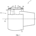
- Fig. 1 is a diagrammatic side view of a typical known turbofan engine 1 having a fan case 11 defining a fan duct 12 which contains a rotating disc of fan blades 13. The fan blades 13 rotate around a central longitudinal axis 14 of the engine 1.
- the fan case 11 is annular and is centred on the longitudinal axis 14.
- the fan case 11 is shown partly cut away in Fig. 1 in order to diagrammatically illustrate the fact that the fan case 11 includes an annular containment case 2 positioned around the periphery of the disc of fan blades 13 in order to contain any broken fan blade 13.
- the containment case 2 comprises a generally-cylindrical barrel or housing 3 at the front end of which is an outwardly-extending annular flange 41 and at the rear end of which is an outwardly-extending annular flange 42.
- the containment case 2 is centred on the longitudinal axis 14 of the engine 1 and is held in position by being fastened to other components of the fan case 11 such as an annular front leading edge 51 and an annular rear edge 52.
- the flanges 41 and 42 may be provided with holes for fasteners which are used to attach the containment case 2 to the structure of the leading and rear edges 51, 52.
- Fig. 2 is a diagrammatic perspective view of a containment case 2 generally similar to the one shown in Fig. 1 except that in Fig. 2 the generally-cylindrical housing 3 is slightly tapered in the direction of the longitudinal axis 14.
- the actual internal contour or profile of the housing 3 may be optimised to suit the requirements of a particular engine 1.
- ATL automated tape laying
- the plies of the flange are hand laid and must be intermeshed with the machine-laid plies of the housing. This tends to produce a flange of inconsistent quality and, in order to compensate for this, a flange which is heavier than it needs to be because it is using an excess of composite material.
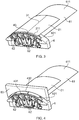
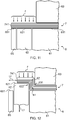
- the experimental tool for forming (bending) a second part 43 to form a flange 4 (corresponding, for example, to part of the front flange 41) is shown in Figs. 3 to 6 .
- the experimental tool incorporates a first part 61 of a cylindrical mould or mandrel 6 and a circumferential line of movable blocks 62.
- An experimental part 21 of the containment case 2 is laid-up as a preform on a mould surface 611 of the first mould part 61 and on mould surfaces 621 of the movable blocks 62.
- the preform comprises the second part 43 and a first or main part 31.
- the second part 43 is laid-up on the mould surfaces 621 and the first part 31 is laid-up on the mould surface 611.
- Pre-impregnated uni-directional tape making up the composite material of the experimental part 21 is laid-up obliquely (e.g. at plus 60° and at minus 60° relative to the circumferential direction) in both the first part 31 and the second part 43.
- the circumferential direction corresponds to the boundary line 211 between the parts 31, 43.
- Circumferential tape (0° tape) is laid-up in the first part 31 but not in the second part 43.
- Perpendicular tape (90° tape) is laid up in the second part 43 and extends a short distance into the first part 31.
- the tape is 0.25 mm thick and has a typical width of 75 mm to 150 mm.
- Such tape is suited to being laid-up by the head of an ATL machine.
- the tape is laid-up to form a stack of plies, and the number of ply layers may be 10 or more, preferably 20 or more, or preferably 30 or more.
- the laid-up tape of the experimental part 21 is cut back so that the circumferential free edge 431 of the second part 43 does not project beyond movable blocks 62 of the mould 6.
- a female forming tool 63 (see Fig. 4 ) is then clamped down onto the part of the first part 31 immediately adjacent the second part 43.
- the mould 6 is then placed in an oven and heated to a first temperature, e.g. 80°C, at which the resin of the pre-preg tape becomes fluid enough (has a low enough viscosity) to facilitate the forming operation which is about to occur.
- a first temperature e.g. 80°C
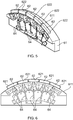
- the blocks 62 are advanced in a radially outward direction from their retracted or flush position to the advanced position shown in Figs. 5 and 6 by actuating actuators 64 such as pneumatic or hydraulic pistons. This forms or flexes upwards the second part 43 to form the flange 4 projecting outwards relative to the first part 31.
- the blocks 62 are advanced by a distance which is at least the width 432 of the second part 43 so that the flange 4 that is formed is an upright wall relative to the first part 31.
- the temperature in the oven is then raised to a second, higher temperature in order to continue and complete the curing of the composite tape material.
- the second temperature may be 135°C.
- the blocks 62 may be retracted to the position shown in Figs. 3 and 4 .
- the female tool 63 may be removed, and the experimental part 21 removed from the mould 6.
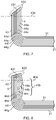
- Figs. 7 and 8 are diagrammatic cross-sectional views through the flange wall 4 (the second part 43) and the adjacent part of the first part 31 after the forming operation has been performed, and Fig. 7 shows the outcome of a correct forming operation and Fig. 8 shows the outcome of an incorrect forming operation.
- the flange 4 may be trimmed to a desired height along a cut line 434 and this will remove the unwanted bookend effect 433.
- the bending upwards of the second part 43 will tend to place the plies at the inside of the bend (such as plies 44a and 44b) in compression and will tend to place the plies at the outside of the bend (such as plies 44f and 44g) in tension.
- a flange 4 as shown in Fig. 8 may be the end result.
- the forming (bending) has been performed too quickly, and the compression of the plies at the inside of the bend (such as plies 44a and 44b) has resulted in them undergoing wrinkling or buckling as shown at area 435. Even after the flange wall 4 has been trimmed to height along the cut line 434, some of the unwanted distortion 435 will still remain.
- EP-1393875-A1 discloses a method for forming composite materials in accordance with the pre-characterising portion of claim 1.
- FR-2879497-A1 discloses apparatus for fabricating reinforced composite materials.
- Any uni-directional ply material located towards the inside of the second bend will also be kept in tension along its length during the forming operation, and this will prevent any distortion of that ply material at the inside of the second bend.
- the second bend balances the first bend because it bends in the opposite direction to the first bend.
- the flange comprises tape which is at an oblique angle and/or is perpendicular relative to the first edge of the main body.
- the first and second parts of the preform each include tape laid at an oblique angle relative to the first edge of the main body.
- the oblique angle (the included angle relative to the first edge of the main body) may be 10° to 80°. Alternatively, the range could be 20° to 70°, or 30° to 60°. In a particularly preferred embodiment, all of the oblique-angle tapes are laid at an included angle relative to the first edge (wherein the first edge corresponds to the boundary between the first and second parts of the preform) of substantially 60°.
- each of the plies comprises the uni-directional ply material. This helps to maximise the benefit of the present invention.
- the uni-directional ply material is pre-impregnated uni-directional tape containing any suitable resin such as epoxy resin.
- each ply is made of such tape.
- the plies may be woven, non-woven or a combination of woven plies and non-woven plies.
- the plies which are laid-up to produce the preform could be "dry" reinforcement (such as fiber tow) and the resin is added later on.
- the resin could be added before, during or after the flange forming step, for example by using the resin transfer moulding (RTM) technique.
- the mould comprises a first mould portion, the movable mould portions adjacent the first mould portion, and a second mould portion adjacent the movable mould portions; and in the laying-up step, the first part of the preform is laid-up on the first mould portion, the proximal portion of the second part of the preform is laid-up on the movable mould portions, and the distal portion of the second part of the preform is laid-up on the second mould portion.
- the second mould portion may have a free edge which is used to define the free edge of the laid-up distal portion of the second part of the preform.
- the plies may be laid-up past the free edge of the second mould portion and then trimmed back to the free edge.
- the second mould portion may be selected from a set of second mould portions having different sizes or dimensions in the direction corresponding to the unformed height of the lip portion.
- the set of second mould portions may have different thicknesses.
- the mould portions provide an annular (usually, a generally-cylindrical) mould surface.
- the mould surface is circular.
- the movable mould portions will move radially outwards during the forming step.
- the plies of the second part of the preform do not include any circumferential tape because such tape would impede the forming operation by resisting the increase in diameter of the second part of the preform as it is radially outwardly formed.
- the preform is covered with a vacuum bag membrane and during the forming step a vacuum is applied to the preform.
- An elastic membrane may be chosen that is flexible as well as stretchable.
- the vacuum bag membrane presses or holds the distal portion of the second part of the preform against the mould surfaces of the movable portions of the mould as the movable portions advance and create the second bend.
- the holding or clamping force provided by the vacuum bag membrane is provided by atmospheric pressure acting on the membrane and thus on the preform.
- a force applied to the distal portion of the second part of the preform during the forming operation initially presses the distal portion against the second mould portion.
- the distal portion slides onto the movable mould portions as the movable mould portions advance, and the distal portion is pressed against the movable mould portions during the rest of the forming operation, as the second bend is created.
- the method further comprises the step of positioning a forming tool to hold the first part of the preform against the mould; and in the forming step, the advancing movable portions of the mould form the proximal portion of the second part of the preform around the forming tool to create the first bend.
- a forming tool may not be needed if the first part of the preform has sufficient strength to remain substantially unaffected by the forming of the flange.
- the first part of the preform could be annular and incorporate circumferential reinforcement adjacent to the flange, such as circumferential or 0° tapes. This reinforcement enables the first part of the preform to resist being increased in diameter by the forming operation.
- the preform is heated to a first temperature and the forming step is performed; and the curing step is performed at a second temperature higher than the first temperature.
- the heating to the first temperature helps the plies at the first and second bends to slip over one another during the flexing of the forming step.
- the subsequent heating to the second, higher temperature is then used to perform or complete the curing step.
- the heating to the first temperature may conveniently be the first part of the curing operation.
- the first temperature may, for example, be between 40° and 100°C, or between 50° and 90°C, or between 60° and 80°C. In our current embodiment, we use 80°C.
- the second temperature made be 120°C or higher. In our current embodiment, we use a temperature of about 135°C.
- the plies of the first and second parts of the preform include tape laid at an oblique angle to the boundary between the first and second preform parts.
- the tape laid at an oblique angle may be laid at an included angle relative to the boundary between the first and second preform parts of 10° to 80°.
- the range may be 20° to 70°, or 30° to 60°.
- all of the oblique angle tapes are laid at an included angle of substantially 60°.
- the oblique-angle tape extends to the free edge of the distal portion of the second part of the preform from the first part of the preform.
- the plies of the first and second parts of the preform include tape laid at a perpendicular angle to the boundary between the first and second preform parts.
- the perpendicular tape may extend to the free edge of the distal portion of the second part of the preform from the first part of the preform.
- the plies at the boundary between the first and second preform parts may be stacked having a regularly-repeating pattern of plies.
- An example of such a pattern is a ply with perpendicular-angle tape, a ply with oblique-angle tape at plus ⁇ ° (such as plus 60°) and a ply with oblique-angle tape at minus ⁇ ° (such as minus 60°).
- This pattern then repeats to provide the required depth of plies in the preform, or at least a substantial part (e.g. the central part) of the required depth of plies.
- Different patterns might be used at the upper and lower surfaces of the preform.
- the first part of the preform has a central zone and an edge zone which is adjacent the boundary between the first and second preform parts; the central zone of the first part of the preform does not include perpendicular-angle tape; and the edge zone of the first part of the preform includes perpendicular-angle tape.
- Both the central zone and the edge zone may include tape laid generally parallel to the boundary between the first and second preform parts.
- the generally-parallel tape may also be included in the second preform part. If the flange is annular (such as when the flange is part of a containment case) then usually the second preform part will not include any generally-parallel tape because it would impede the forming of the annular flange because the tape would not stretch when forming a flange which projects radially outwards from the annular housing of the containment case.
- the method further comprises the step of, after the curing step, trimming off the lip portion of the flange.
- the lip portion may sometimes not be needed during the eventual use of the composite structure. After the forming of the lip portion has served the purpose, during the manufacturing process, of tensioning the uni-directional ply material in the wall portion and at the first bend (to prevent distortion such as wrinkling) the lip portion may be removed.
- the lip portion will often be retained because it improves the stiffness or rigidity of the flange and thus of the composite structure.
- the composite structure is a containment case for a gas turbine engine
- the containment case comprises the main body in the form of an annular housing and the flange in the form of an annular flange which is positioned at an end of the housing and which has an annular wall portion which is connected to the housing through the first bend and an annular lip portion which is connected to the wall portion through the second bend in the opposite direction to the first bend;
- the preform is an annular preform; and in the forming step, the annular flange is formed by radially outwardly-moving the movable portions of the mould.
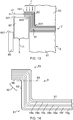
- the mould 6 of the experimental tool of Figs. 3 to 6 is modified by the addition of a second mould portion in the form of an end plate 65 which is positioned adjacent the movable blocks 62 (the movable mould portions).
- the main or first part 61 of the mould (the first mould portion) is fixed to the end plate 65 (the second mould portion) so that both the first and second mould portions 61, 65 are fixed or static relative to the movable blocks 62.
- the mould surface 651 of the end plate 65 combines with the mould surface 611 of the first part 61 and the mould surfaces 621 of the movable blocks 62 to form an overall mould surface which is a curved part of a generally-cylindrical mould surface, and a preform 7 is laid-up on the mould surfaces 611, 621, 651 by the head of an ATL machine (see Fig. 9 ).
- the composite material that is laid-up to form the preform 7 is the same pre-impregnated uni-directional tape that is described above in relation to laying-up the experimental part 21, such as carbon fibre tape containing epoxy resin.
- the preform is laid-up with a first part 71 on the mould surface 611 and a second part 72 on the mould surfaces 621, 651.
- the second part 72 is split into a proximal portion 73 which is laid-up on the surface 621 of the movable blocks 62 and a distal portion 74 which is laid-up on the surface 651 of the end plate 65.
- the first part 71 of the preform 7 corresponds to the first part 31 of the experimental part 21.
- the proximal portion 73 of the preform 7 corresponds to the second part 43 of the experimental part 21.
- the preform 7 is longer than the experimental part 21 (in the leftward direction in Fig. 9 ) because the preform includes the distal portion 74 and the mould 6 includes the end plate 65.
- Oblique-angle tape is laid-up in both the first and second parts 71, 72 and at least some of these tapes extend from the first part 71 to the free edge 741 of the distal portion 74.
- each oblique-angle tape extends the full length of the preform 7 from the end of the preform opposite to the free edge 741 (i.e. from the right-hand end of the preform as viewed in Fig. 9 ) through to the free edge 741 (i.e. to the left-hand end of the preform as viewed in Fig. 9 ).
- the first part 71 has a central zone 75 and an edge zone 76 which is adjacent the boundary 77 between the first part 71 and the second part 72.
- Perpendicular-angle tape (90° tape) is laid-up to extend from the edge zone 76 to the free edge 741 of the distal portion 74.
- the central zone 75 does not include any perpendicular-angle tape.
- Circumferential tape (0° tape) which is generally-parallel to the boundary 77 (i.e. the direction perpendicular to the plane of the paper in Fig. 9 ) is laid-up in the first part 71 but not in the second part 72.
- Seven plies 78a-78g are shown in Figs. 9 to 14 for reasons of clarity, but in many practical embodiments the number of ply layers will be greater, such as 10 or more, or 20 or more, or 30 or more.
- a membrane 79 of a vacuum bag is positioned over the preform 7 and sealed around its periphery 791 to the mould 6 so that air can be extracted from the space 792 between the membrane 79 and the preform 7 to enable pressure (atmospheric pressure acting on the membrane 79) to be applied to the preform 7 during the subsequent forming and curing operations.
- the vacuum bag membrane 79 is not shown in Figs. 11 to 13 for reasons of clarity. Instead, arrows F are used to depict the clamping or holding force exerted by the membrane 79 on the preform 7 which serves to press the second part 72 against the mould 6 during the forming operation.
- the female forming tool 63 is moved into position and clamps or holds down the edge zone 76 of the first part 71 of the preform 7.
- the forming tool 63 is positioned adjacent the boundary 77 but is offset from the boundary by a short distance corresponding to the thickness of the proximal portion 73 of the second part 72 in order to accommodate the movement of the proximal portion 73 during the subsequent forming operation.
- the next stage of the manufacturing process is shown in Fig. 12 .
- the temperature is raised to say 80°C in order to soften the resin in the plies 78 so that they can more easily slide relative to one another.
- the movable blocks 62 are advanced (raised up or moved radially outwards) a first distance L1 from their retracted positions.
- the force F presses down on the distal portion 74 as the distal portion 74 is lifted off the mould surface 651 and is pulled sideways (a second distance L2) onto the mould surface 621.
- a circumferential edge 622 of the movable blocks 62 pushes against the plies 78 of the preform 7 and forms them around a circumferential edge 631 of the forming tool 63 so as to create a first bend 81 in the preform 7.
- An interim bend 82 is also created in the preform 7.
- the distance L2 is approximately the same as the distance L1 because the perpendicular-angle tape prevents the plies 78 from stretching during the forming operation.
- the forming operation continues as the movable blocks 62 advance from first distance L1 ( Fig. 12 ) to third distance L3 ( Fig. 13 ).
- the distal portion 74 is pulled further sideways across the mould surface 621 from second distance L2 ( Fig. 12 ) to fourth distance L4 ( Fig. 13 ).
- the distal portion 74 continues to be pressed against the mould surface 621 by the force F resulting from the atmospheric pressure acting on the evacuated vacuum bag membrane 79.
- the circumferential edge 622 of the movable blocks 62 pushes the interim bend 82 to a final position ( Fig. 13 ) defining a second bend 83 of the preform 7.
- the stroke length (L3) of the movement of the movable blocks 62 is approximately the same as the distance L4.
- the forming operation is complete, and the temperature is increased to say 135°C and the curing operation is performed or completed in order to cure the resin in the composite tape of the plies 78.
- the female forming tool 63 is removed, and the vacuum is released from the space 792 inside the membrane 79.
- the membrane 79 is removed from the mould 6 and the formed and cured preform 7 (now transformed into a composite article 9) is lifted off the mould 6.
- the left-hand end of the composite article 9 is shown in Fig. 14 at an enlarged scale.
- the article 9 comprises a main body 91 connected via the first bend 81 to a flange 92, and the flange 92 comprises a wall portion 93 which is connected via the second bend 83 to a lip portion 94.
- the main body 91 would be annular, and the wall portion 93 and the lip portion 94 would also each be annular.
- the lip portion 94 could be left on the containment case in order to provide additional stiffness to the annular flange 92. This would improve the hoop strength of the containment case.
- the lip portion is not needed in the finished article, it could be cut off along a cut line 95 which is positioned below and generally parallel to the undersurface of the lip portion 94.
- the wall portion 93 is perpendicular to the main body 91 and this maximises the strengthening effect of the wall portion imparted to the main body.
- the lip portion 94 is perpendicular to the wall portion 93 and this maximises the strengthening effect of the lip portion imparted to the wall portion.
- the lip portion could be given a different orientation relative to the wall portion.
- the radius of curvature of the circumferential edges 631 and 622 may be set so as to impart a desired radius of curvature to the inside of the first bend 81 and the second bend 83 respectively, because the force F ensures that the preform 7 is tightly moulded around the circumferential edges during the forming operation.
- the presence of the interim bend 82 ensures that the plies (such as plies 78a and 78b) near the inside of the first bend 81 are kept in tension along the length of the oblique-angle and perpendicular-angle tapes of those plies, so that wrinkling or buckling of the plies does not occur.
- the two bends balance one another because they are in opposite directions, and by creating the two bends at the same time during the forming operation the beneficial tensioning effect is achieved.
- the presence of the first bend 81 ensures that the plies (such as plies 78f and 78g) near the inside of the interim bend 82 (and the second bend 83) are kept in tension during the forming operation to prevent distortion appearing in the wall portion 93.
- the stroke length L3 is set to be more than the width L5 (see Fig. 9 ) of the circumferential strip comprising the distal portion 74 of the preform 7 so that the lip portion 94 is supported on the surface 621 of the movable blocks 62 during the curing operation.
- L3 is set to be less than the width L6 (see Fig. 9 ) of the circumferential strip comprising the second part 72 of the preform 7 so that there is still some material of the distal portion 74 left at the end of the stroke of the movable blocks 62 to form the lip portion 94. It can be visualised that, if for example L3 is significantly bigger than L6, all of the material of the second part 72 of the preform 7 would be converted into wall portion 93 during the forming operation.
- the tape is laid-up so that the preform 7 has a substantially uniform ply depth for the second part 72 and at least the edge zone 76 of the first part 71. This helps to ensure smooth bending of the plies during the forming operation.
Landscapes
- Engineering & Computer Science (AREA)
- Mechanical Engineering (AREA)
- Chemical & Material Sciences (AREA)
- Composite Materials (AREA)
- General Engineering & Computer Science (AREA)
- Moulding By Coating Moulds (AREA)
- Shaping Of Tube Ends By Bending Or Straightening (AREA)
Applications Claiming Priority (2)
| Application Number | Priority Date | Filing Date | Title |
|---|---|---|---|
| GB1020742.1A GB2486231B (en) | 2010-12-07 | 2010-12-07 | Composite structure |
| PCT/GB2011/052412 WO2012076875A1 (en) | 2010-12-07 | 2011-12-06 | Method of forming a composite structure comprising a flange |
Publications (2)
| Publication Number | Publication Date |
|---|---|
| EP2648893A1 EP2648893A1 (en) | 2013-10-16 |
| EP2648893B1 true EP2648893B1 (en) | 2017-11-01 |
Family
ID=43531612
Family Applications (1)
| Application Number | Title | Priority Date | Filing Date |
|---|---|---|---|
| EP11796792.7A Active EP2648893B1 (en) | 2010-12-07 | 2011-12-06 | Method of forming a composite structure comprising a flange. |
Country Status (7)
Families Citing this family (46)
| Publication number | Priority date | Publication date | Assignee | Title |
|---|---|---|---|---|
| US9140135B2 (en) * | 2010-09-28 | 2015-09-22 | United Technologies Corporation | Metallic radius block for composite flange |
| GB201100585D0 (en) * | 2011-01-14 | 2011-03-02 | Magma Global Ltd | Connector arrangement for composite pipe |
| WO2014001593A1 (es) * | 2012-06-29 | 2014-01-03 | Airbus Operations S.L. | Larguerillo en forma de "t" con extremo del alma redondeado y su método de fabricación |
| US9248587B2 (en) * | 2012-07-05 | 2016-02-02 | General Electric Company | Apparatus for manufacturing a flanged composite component and methods of manufacturing the same |
| US9149997B2 (en) | 2012-09-14 | 2015-10-06 | United Technologies | Composite flange from braided preform |
| US20140119904A1 (en) | 2012-11-01 | 2014-05-01 | United Technologies Corporation | In-situ pressure enhanced processing of composite articles |
| JP5598528B2 (ja) * | 2012-11-29 | 2014-10-01 | 株式会社豊田自動織機 | 筒状繊維構造体 |
| EP2746018B1 (en) * | 2012-12-18 | 2017-03-01 | Airbus Operations GmbH | Method and apparatus for production of composite preform |
| US20150336337A1 (en) * | 2012-12-19 | 2015-11-26 | Fives Machining Systems, Inc. | Process for molding a 3-dimensional part |
| EP2883688B1 (fr) | 2013-12-13 | 2021-09-22 | Safran Aero Boosters SA | Carter annulaire composite de compresseur de turbomachine et procédé d'obtention de celui-ci |
| US9796117B2 (en) | 2014-06-03 | 2017-10-24 | Gkn Aerospace Services Structures Corporation | Apparatus for forming a flange |
| US9914268B2 (en) * | 2014-06-04 | 2018-03-13 | The Boeing Company | Systems and methods for defining a surface contour of a layered charge of material |
| US20160061222A1 (en) * | 2014-09-03 | 2016-03-03 | Jeffrey William Robinson | Composite fan housing and method |
| DE102014015414B4 (de) * | 2014-10-20 | 2018-02-01 | Premium Aerotec Gmbh | Vorrichtung und Verfahren zur Herstellung eines schalenförmigen Faserverbundteils |
| JP6488696B2 (ja) * | 2014-12-25 | 2019-03-27 | 三菱ケミカル株式会社 | 繊維強化複合材料成形体の製造方法 |
| US10479029B2 (en) * | 2015-01-16 | 2019-11-19 | The Boeing Company | Composite forming apparatus |
| GB201507414D0 (en) * | 2015-04-30 | 2015-06-17 | Composite Technology & Applic Ltd | A method of Manufacturing a Composite Component |
| GB201507412D0 (en) * | 2015-04-30 | 2015-06-17 | Composite Technology & Applic Ltd | A method and Apparatus for Forming a Composite Component |
| GB201507418D0 (en) | 2015-04-30 | 2015-06-17 | Composite Technology & Applic Ltd | A tool for forming a composite component |
| US10024193B2 (en) * | 2015-11-19 | 2018-07-17 | General Electric Company | Pin supported CMC shroud |
| CN112092415B (zh) * | 2016-04-06 | 2022-06-21 | 劳斯莱斯股份有限公司 | 用于制造复合部件的方法 |
| US10105940B2 (en) * | 2016-04-18 | 2018-10-23 | The Boeing Company | Formation of composite laminates having one or more divergent flanges |
| DE102016125959A1 (de) * | 2016-12-30 | 2018-07-05 | Airbus Operations Gmbh | Membranwerkzeug zum Umformen von Verstärkungsfaserlagen zu vorumgeformten T-förmigen Profilen |
| DE102016125958A1 (de) * | 2016-12-30 | 2018-07-05 | Airbus Operations Gmbh | Werkzeug zum Formen eines T-förmigen Halbzeugs |
| DE102017101346A1 (de) | 2017-01-25 | 2017-12-28 | Voith Patent Gmbh | Verfahren zum herstellen eines rohres |
| US11242866B2 (en) | 2018-08-01 | 2022-02-08 | General Electric Company | Casing having a non-axisymmetric composite wall |
| EP3608092B1 (en) | 2018-08-10 | 2023-06-28 | Crompton Technology Group Limited | Composite connector and method of manufacturing the same |
| EP3608093B1 (en) | 2018-08-10 | 2024-04-17 | Crompton Technology Group Limited | Composite connector and method of manufacturing the same |
| EP3608091A1 (en) | 2018-08-10 | 2020-02-12 | Crompton Technology Group Limited | Composite connector and method of manufacturing the same |
| EP3608094B1 (en) | 2018-08-10 | 2024-09-25 | Crompton Technology Group Limited | Composite connector and method of manufacturing the same |
| EP3608095A1 (en) | 2018-08-10 | 2020-02-12 | Crompton Technology Group Limited | Composite connectors and methods of manufacturing the same |
| EP3608089B1 (en) | 2018-08-10 | 2022-10-12 | Crompton Technology Group Limited | Composite connector and method of manufacturing the same |
| WO2020162027A1 (ja) | 2019-02-07 | 2020-08-13 | 三菱重工業株式会社 | 積層体成形装置及び積層体成形方法 |
| JP7039738B2 (ja) | 2019-02-07 | 2022-03-22 | 三菱重工業株式会社 | 積層体成形方法及び積層体成形装置 |
| EP3805623B1 (en) | 2019-10-07 | 2023-11-29 | Crompton Technology Group Limited | Fibre reinforced polymer composite pipes and method of making thereof |
| ES2958761T3 (es) * | 2019-11-13 | 2024-02-14 | Airbus Operations Slu | Dispositivo y método de formación de un laminado compuesto para obtener un perfil en forma de Z |
| ES2935701T3 (es) * | 2019-12-17 | 2023-03-09 | Airbus Defence And Space Sau | Método para la fabricación de componentes de compuestos de fibra |
| EP4553699A3 (en) * | 2020-01-31 | 2025-08-06 | Dassault Systèmes | Structural simulation of a mechanical part |
| US11260607B2 (en) | 2020-02-11 | 2022-03-01 | The Boeing Company | Forming systems and methods for drape forming a composite charge |
| US11498288B2 (en) | 2020-02-11 | 2022-11-15 | The Boeing Company | Forming systems and methods for drape forming a composite charge |
| CN114026529B (zh) * | 2020-03-20 | 2024-04-09 | 京东方科技集团股份有限公司 | 模具、显示装置的制备方法 |
| CN112248415B (zh) * | 2020-09-28 | 2021-11-26 | 常州市新创智能科技有限公司 | 一种横压式直z隔框预成型装置 |
| IT202000028046A1 (it) * | 2020-11-23 | 2022-05-23 | Leonardo Spa | Metodo e dispositivo per la fabbricazione di un elemento strutturale in materiale composito con profilo a z |
| US11931975B2 (en) | 2021-02-19 | 2024-03-19 | The Boeing Company | Forming systems and methods for forming an elongate charge of composite material |
| CN114030203A (zh) * | 2021-11-08 | 2022-02-11 | 北京航空航天大学 | 一种制造航空发动机复合材料风扇叶身特征件的工装 |
| GB202312199D0 (en) * | 2023-08-09 | 2023-09-20 | Rolls Royce Plc | Method and system for manufacturing composite component |
Citations (1)
| Publication number | Priority date | Publication date | Assignee | Title |
|---|---|---|---|---|
| US20070086854A1 (en) * | 2005-10-18 | 2007-04-19 | General Electric Company | Methods and apparatus for assembling composite structures |
Family Cites Families (15)
| Publication number | Priority date | Publication date | Assignee | Title |
|---|---|---|---|---|
| AT349766B (de) * | 1977-06-20 | 1979-04-25 | Isovolta | Heiss verformbare kunstharz-schichtpressstoff- platte sowie verfahren zum verformen solcher platten |
| US4777005A (en) * | 1986-02-03 | 1988-10-11 | The Board Of Trustees Of The Leland Stanford Junior University | Process for shaping fiber composite materials |
| JPH03295631A (ja) * | 1990-04-13 | 1991-12-26 | Fuji Heavy Ind Ltd | 熱可塑性複合材料の成形装置 |
| US5348602A (en) * | 1993-06-08 | 1994-09-20 | General Electric Company | Method for making a bonded laminated article bend portion |
| US5639535A (en) * | 1996-06-06 | 1997-06-17 | The Boeing Company | Composite interleaving for composite interfaces |
| US6814916B2 (en) | 2002-08-30 | 2004-11-09 | The Boeing Company | Forming method for composites |
| JP3782072B2 (ja) * | 2003-05-30 | 2006-06-07 | 川崎重工業株式会社 | 複合材型材の成形方法及び装置 |
| US7335012B2 (en) * | 2004-12-22 | 2008-02-26 | General Electric Company | Apparatus for fabricating reinforced composite materials |
| US8632653B2 (en) * | 2005-05-03 | 2014-01-21 | The Boeing Company | Method of manufacturing curved composite structural elements |
| US7588711B2 (en) | 2006-11-21 | 2009-09-15 | The Boeing Company | Method for forming a composite support beam |
| GB2452298B (en) | 2007-08-30 | 2010-01-13 | Gkn Aerospace Services Ltd | Composite structure |
| US9017814B2 (en) * | 2007-10-16 | 2015-04-28 | General Electric Company | Substantially cylindrical composite articles and fan casings |
| US8540833B2 (en) * | 2008-05-16 | 2013-09-24 | The Boeing Company | Reinforced stiffeners and method for making the same |
| JP5242471B2 (ja) * | 2008-11-05 | 2013-07-24 | 古河電気工業株式会社 | 熱可塑性樹脂シートの折曲げ成形用金型、折曲げ成形方法、及び折曲げ成形体 |
| DE102008057783B3 (de) | 2008-11-17 | 2010-02-04 | Eads Deutschland Gmbh | Vorrichtung und Verfahren zum Umfalten eines zur Herstellung eines Faserverbundbauteils vorgesehenen textilen Halbzeugprofils |
-
2010
- 2010-12-07 GB GB1020742.1A patent/GB2486231B/en active Active
-
2011
- 2011-12-06 JP JP2013542605A patent/JP5931906B2/ja active Active
- 2011-12-06 US US13/991,575 patent/US9517613B2/en active Active
- 2011-12-06 EP EP11796792.7A patent/EP2648893B1/en active Active
- 2011-12-06 CN CN201180066962.1A patent/CN103338914B/zh active Active
- 2011-12-06 CA CA2820150A patent/CA2820150C/en active Active
- 2011-12-06 WO PCT/GB2011/052412 patent/WO2012076875A1/en active Application Filing
Patent Citations (1)
| Publication number | Priority date | Publication date | Assignee | Title |
|---|---|---|---|---|
| US20070086854A1 (en) * | 2005-10-18 | 2007-04-19 | General Electric Company | Methods and apparatus for assembling composite structures |
Also Published As
| Publication number | Publication date |
|---|---|
| US20130266431A1 (en) | 2013-10-10 |
| US9517613B2 (en) | 2016-12-13 |
| JP5931906B2 (ja) | 2016-06-08 |
| CA2820150A1 (en) | 2012-06-14 |
| CN103338914B (zh) | 2016-08-10 |
| GB2486231B (en) | 2013-04-03 |
| GB2486231A (en) | 2012-06-13 |
| EP2648893A1 (en) | 2013-10-16 |
| JP2014504220A (ja) | 2014-02-20 |
| CN103338914A (zh) | 2013-10-02 |
| GB201020742D0 (en) | 2011-01-19 |
| WO2012076875A1 (en) | 2012-06-14 |
| CA2820150C (en) | 2018-11-20 |
Similar Documents
| Publication | Publication Date | Title |
|---|---|---|
| EP2648893B1 (en) | Method of forming a composite structure comprising a flange. | |
| CN111452947B (zh) | 成形复合桁条 | |
| CN108725749B (zh) | 纤维增强复合材料翼型件结构 | |
| JP5806930B2 (ja) | 輪郭に合致した複合構造物を生産する方法 | |
| US8951375B2 (en) | Methods and systems for co-bonding or co-curing composite parts using a rigid/malleable SMP apparatus | |
| US8585952B2 (en) | Pressure molded preform process for composite structures | |
| CA2808923C (en) | Methods and systems for co-bonding or co-curing composite parts using a rigid/malleable smp apparatus | |
| US8815145B2 (en) | Methods and systems for fabricating composite stiffeners with a rigid/malleable SMP apparatus | |
| CA2814033C (en) | Method of manufacturing a composite structure and composite structure obtained thereby | |
| US8734703B2 (en) | Methods and systems for fabricating composite parts using a SMP apparatus as a rigid lay-up tool and bladder | |
| JP5751415B2 (ja) | ガスタービンエンジン用ブレードの製造方法 | |
| US20110186209A1 (en) | Complex geometries made of composite material and forming process for same | |
| CN107567381B (zh) | 制造复合部件的方法 | |
| CN110884161B (zh) | 复合材料的弯曲欧米茄桁条和z形桁条制造方法以及具有曲率的复合材料加筋板的制造方法 | |
| CA2808926A1 (en) | Methods and systems for forming integral composite parts with a smp apparatus |
Legal Events
| Date | Code | Title | Description |
|---|---|---|---|
| PUAI | Public reference made under article 153(3) epc to a published international application that has entered the european phase |
Free format text: ORIGINAL CODE: 0009012 |
|
| 17P | Request for examination filed |
Effective date: 20130621 |
|
| AK | Designated contracting states |
Kind code of ref document: A1 Designated state(s): AL AT BE BG CH CY CZ DE DK EE ES FI FR GB GR HR HU IE IS IT LI LT LU LV MC MK MT NL NO PL PT RO RS SE SI SK SM TR |
|
| DAX | Request for extension of the european patent (deleted) | ||
| 17Q | First examination report despatched |
Effective date: 20160503 |
|
| GRAP | Despatch of communication of intention to grant a patent |
Free format text: ORIGINAL CODE: EPIDOSNIGR1 |
|
| STAA | Information on the status of an ep patent application or granted ep patent |
Free format text: STATUS: GRANT OF PATENT IS INTENDED |
|
| RIC1 | Information provided on ipc code assigned before grant |
Ipc: B32B 37/02 20060101ALI20161118BHEP Ipc: B29C 53/04 20060101ALI20161118BHEP Ipc: B29L 9/00 20060101ALN20161118BHEP Ipc: F01D 21/04 20060101ALI20161118BHEP Ipc: B29C 57/00 20060101ALI20161118BHEP Ipc: F01D 25/24 20060101ALI20161118BHEP Ipc: B29K 105/08 20060101ALN20161118BHEP Ipc: B29C 70/34 20060101AFI20161118BHEP Ipc: B29L 31/30 20060101ALN20161118BHEP |
|
| INTG | Intention to grant announced |
Effective date: 20161205 |
|
| GRAJ | Information related to disapproval of communication of intention to grant by the applicant or resumption of examination proceedings by the epo deleted |
Free format text: ORIGINAL CODE: EPIDOSDIGR1 |
|
| STAA | Information on the status of an ep patent application or granted ep patent |
Free format text: STATUS: EXAMINATION IS IN PROGRESS |
|
| GRAP | Despatch of communication of intention to grant a patent |
Free format text: ORIGINAL CODE: EPIDOSNIGR1 |
|
| STAA | Information on the status of an ep patent application or granted ep patent |
Free format text: STATUS: GRANT OF PATENT IS INTENDED |
|
| INTC | Intention to grant announced (deleted) | ||
| INTG | Intention to grant announced |
Effective date: 20170509 |
|
| RIC1 | Information provided on ipc code assigned before grant |
Ipc: B29K 105/08 20060101ALN20170424BHEP Ipc: B29C 70/34 20060101AFI20170424BHEP Ipc: B29C 57/00 20060101ALI20170424BHEP Ipc: F01D 21/04 20060101ALI20170424BHEP Ipc: B29L 31/30 20060101ALN20170424BHEP Ipc: B32B 37/02 20060101ALI20170424BHEP Ipc: B29L 9/00 20060101ALN20170424BHEP Ipc: F01D 25/24 20060101ALI20170424BHEP Ipc: B29C 53/04 20060101ALI20170424BHEP |
|
| GRAS | Grant fee paid |
Free format text: ORIGINAL CODE: EPIDOSNIGR3 |
|
| GRAA | (expected) grant |
Free format text: ORIGINAL CODE: 0009210 |
|
| STAA | Information on the status of an ep patent application or granted ep patent |
Free format text: STATUS: THE PATENT HAS BEEN GRANTED |
|
| AK | Designated contracting states |
Kind code of ref document: B1 Designated state(s): AL AT BE BG CH CY CZ DE DK EE ES FI FR GB GR HR HU IE IS IT LI LT LU LV MC MK MT NL NO PL PT RO RS SE SI SK SM TR |
|
| REG | Reference to a national code |
Ref country code: GB Ref legal event code: FG4D |
|
| REG | Reference to a national code |
Ref country code: CH Ref legal event code: EP Ref country code: AT Ref legal event code: REF Ref document number: 941625 Country of ref document: AT Kind code of ref document: T Effective date: 20171115 |
|
| REG | Reference to a national code |
Ref country code: FR Ref legal event code: PLFP Year of fee payment: 7 |
|
| REG | Reference to a national code |
Ref country code: IE Ref legal event code: FG4D |
|
| REG | Reference to a national code |
Ref country code: DE Ref legal event code: R096 Ref document number: 602011042979 Country of ref document: DE |
|
| REG | Reference to a national code |
Ref country code: NL Ref legal event code: MP Effective date: 20171101 |
|
| REG | Reference to a national code |
Ref country code: LT Ref legal event code: MG4D |
|
| REG | Reference to a national code |
Ref country code: AT Ref legal event code: MK05 Ref document number: 941625 Country of ref document: AT Kind code of ref document: T Effective date: 20171101 |
|
| PG25 | Lapsed in a contracting state [announced via postgrant information from national office to epo] |
Ref country code: NL Free format text: LAPSE BECAUSE OF FAILURE TO SUBMIT A TRANSLATION OF THE DESCRIPTION OR TO PAY THE FEE WITHIN THE PRESCRIBED TIME-LIMIT Effective date: 20171101 Ref country code: NO Free format text: LAPSE BECAUSE OF FAILURE TO SUBMIT A TRANSLATION OF THE DESCRIPTION OR TO PAY THE FEE WITHIN THE PRESCRIBED TIME-LIMIT Effective date: 20180201 Ref country code: SE Free format text: LAPSE BECAUSE OF FAILURE TO SUBMIT A TRANSLATION OF THE DESCRIPTION OR TO PAY THE FEE WITHIN THE PRESCRIBED TIME-LIMIT Effective date: 20171101 Ref country code: FI Free format text: LAPSE BECAUSE OF FAILURE TO SUBMIT A TRANSLATION OF THE DESCRIPTION OR TO PAY THE FEE WITHIN THE PRESCRIBED TIME-LIMIT Effective date: 20171101 Ref country code: ES Free format text: LAPSE BECAUSE OF FAILURE TO SUBMIT A TRANSLATION OF THE DESCRIPTION OR TO PAY THE FEE WITHIN THE PRESCRIBED TIME-LIMIT Effective date: 20171101 Ref country code: LT Free format text: LAPSE BECAUSE OF FAILURE TO SUBMIT A TRANSLATION OF THE DESCRIPTION OR TO PAY THE FEE WITHIN THE PRESCRIBED TIME-LIMIT Effective date: 20171101 |
|
| PG25 | Lapsed in a contracting state [announced via postgrant information from national office to epo] |
Ref country code: IS Free format text: LAPSE BECAUSE OF FAILURE TO SUBMIT A TRANSLATION OF THE DESCRIPTION OR TO PAY THE FEE WITHIN THE PRESCRIBED TIME-LIMIT Effective date: 20180301 Ref country code: RS Free format text: LAPSE BECAUSE OF FAILURE TO SUBMIT A TRANSLATION OF THE DESCRIPTION OR TO PAY THE FEE WITHIN THE PRESCRIBED TIME-LIMIT Effective date: 20171101 Ref country code: GR Free format text: LAPSE BECAUSE OF FAILURE TO SUBMIT A TRANSLATION OF THE DESCRIPTION OR TO PAY THE FEE WITHIN THE PRESCRIBED TIME-LIMIT Effective date: 20180202 Ref country code: HR Free format text: LAPSE BECAUSE OF FAILURE TO SUBMIT A TRANSLATION OF THE DESCRIPTION OR TO PAY THE FEE WITHIN THE PRESCRIBED TIME-LIMIT Effective date: 20171101 Ref country code: LV Free format text: LAPSE BECAUSE OF FAILURE TO SUBMIT A TRANSLATION OF THE DESCRIPTION OR TO PAY THE FEE WITHIN THE PRESCRIBED TIME-LIMIT Effective date: 20171101 Ref country code: AT Free format text: LAPSE BECAUSE OF FAILURE TO SUBMIT A TRANSLATION OF THE DESCRIPTION OR TO PAY THE FEE WITHIN THE PRESCRIBED TIME-LIMIT Effective date: 20171101 Ref country code: BG Free format text: LAPSE BECAUSE OF FAILURE TO SUBMIT A TRANSLATION OF THE DESCRIPTION OR TO PAY THE FEE WITHIN THE PRESCRIBED TIME-LIMIT Effective date: 20180201 |
|
| PG25 | Lapsed in a contracting state [announced via postgrant information from national office to epo] |
Ref country code: CZ Free format text: LAPSE BECAUSE OF FAILURE TO SUBMIT A TRANSLATION OF THE DESCRIPTION OR TO PAY THE FEE WITHIN THE PRESCRIBED TIME-LIMIT Effective date: 20171101 Ref country code: SK Free format text: LAPSE BECAUSE OF FAILURE TO SUBMIT A TRANSLATION OF THE DESCRIPTION OR TO PAY THE FEE WITHIN THE PRESCRIBED TIME-LIMIT Effective date: 20171101 Ref country code: CY Free format text: LAPSE BECAUSE OF FAILURE TO SUBMIT A TRANSLATION OF THE DESCRIPTION OR TO PAY THE FEE WITHIN THE PRESCRIBED TIME-LIMIT Effective date: 20171101 Ref country code: DK Free format text: LAPSE BECAUSE OF FAILURE TO SUBMIT A TRANSLATION OF THE DESCRIPTION OR TO PAY THE FEE WITHIN THE PRESCRIBED TIME-LIMIT Effective date: 20171101 Ref country code: EE Free format text: LAPSE BECAUSE OF FAILURE TO SUBMIT A TRANSLATION OF THE DESCRIPTION OR TO PAY THE FEE WITHIN THE PRESCRIBED TIME-LIMIT Effective date: 20171101 |
|
| REG | Reference to a national code |
Ref country code: CH Ref legal event code: PL |
|
| REG | Reference to a national code |
Ref country code: DE Ref legal event code: R097 Ref document number: 602011042979 Country of ref document: DE |
|
| PG25 | Lapsed in a contracting state [announced via postgrant information from national office to epo] |
Ref country code: RO Free format text: LAPSE BECAUSE OF FAILURE TO SUBMIT A TRANSLATION OF THE DESCRIPTION OR TO PAY THE FEE WITHIN THE PRESCRIBED TIME-LIMIT Effective date: 20171101 Ref country code: PL Free format text: LAPSE BECAUSE OF FAILURE TO SUBMIT A TRANSLATION OF THE DESCRIPTION OR TO PAY THE FEE WITHIN THE PRESCRIBED TIME-LIMIT Effective date: 20171101 Ref country code: IT Free format text: LAPSE BECAUSE OF FAILURE TO SUBMIT A TRANSLATION OF THE DESCRIPTION OR TO PAY THE FEE WITHIN THE PRESCRIBED TIME-LIMIT Effective date: 20171101 Ref country code: SM Free format text: LAPSE BECAUSE OF FAILURE TO SUBMIT A TRANSLATION OF THE DESCRIPTION OR TO PAY THE FEE WITHIN THE PRESCRIBED TIME-LIMIT Effective date: 20171101 |
|
| PLBE | No opposition filed within time limit |
Free format text: ORIGINAL CODE: 0009261 |
|
| STAA | Information on the status of an ep patent application or granted ep patent |
Free format text: STATUS: NO OPPOSITION FILED WITHIN TIME LIMIT |
|
| REG | Reference to a national code |
Ref country code: IE Ref legal event code: MM4A |
|
| PG25 | Lapsed in a contracting state [announced via postgrant information from national office to epo] |
Ref country code: LU Free format text: LAPSE BECAUSE OF NON-PAYMENT OF DUE FEES Effective date: 20171206 Ref country code: MT Free format text: LAPSE BECAUSE OF NON-PAYMENT OF DUE FEES Effective date: 20171206 |
|
| 26N | No opposition filed |
Effective date: 20180802 |
|
| REG | Reference to a national code |
Ref country code: BE Ref legal event code: MM Effective date: 20171231 |
|
| PG25 | Lapsed in a contracting state [announced via postgrant information from national office to epo] |
Ref country code: IE Free format text: LAPSE BECAUSE OF NON-PAYMENT OF DUE FEES Effective date: 20171206 |
|
| PG25 | Lapsed in a contracting state [announced via postgrant information from national office to epo] |
Ref country code: BE Free format text: LAPSE BECAUSE OF NON-PAYMENT OF DUE FEES Effective date: 20171231 Ref country code: SI Free format text: LAPSE BECAUSE OF FAILURE TO SUBMIT A TRANSLATION OF THE DESCRIPTION OR TO PAY THE FEE WITHIN THE PRESCRIBED TIME-LIMIT Effective date: 20171101 Ref country code: LI Free format text: LAPSE BECAUSE OF NON-PAYMENT OF DUE FEES Effective date: 20171231 Ref country code: CH Free format text: LAPSE BECAUSE OF NON-PAYMENT OF DUE FEES Effective date: 20171231 |
|
| PG25 | Lapsed in a contracting state [announced via postgrant information from national office to epo] |
Ref country code: MC Free format text: LAPSE BECAUSE OF FAILURE TO SUBMIT A TRANSLATION OF THE DESCRIPTION OR TO PAY THE FEE WITHIN THE PRESCRIBED TIME-LIMIT Effective date: 20171101 Ref country code: HU Free format text: LAPSE BECAUSE OF FAILURE TO SUBMIT A TRANSLATION OF THE DESCRIPTION OR TO PAY THE FEE WITHIN THE PRESCRIBED TIME-LIMIT; INVALID AB INITIO Effective date: 20111206 |
|
| PG25 | Lapsed in a contracting state [announced via postgrant information from national office to epo] |
Ref country code: MK Free format text: LAPSE BECAUSE OF FAILURE TO SUBMIT A TRANSLATION OF THE DESCRIPTION OR TO PAY THE FEE WITHIN THE PRESCRIBED TIME-LIMIT Effective date: 20171101 |
|
| PG25 | Lapsed in a contracting state [announced via postgrant information from national office to epo] |
Ref country code: TR Free format text: LAPSE BECAUSE OF FAILURE TO SUBMIT A TRANSLATION OF THE DESCRIPTION OR TO PAY THE FEE WITHIN THE PRESCRIBED TIME-LIMIT Effective date: 20171101 |
|
| PG25 | Lapsed in a contracting state [announced via postgrant information from national office to epo] |
Ref country code: PT Free format text: LAPSE BECAUSE OF FAILURE TO SUBMIT A TRANSLATION OF THE DESCRIPTION OR TO PAY THE FEE WITHIN THE PRESCRIBED TIME-LIMIT Effective date: 20171101 |
|
| PG25 | Lapsed in a contracting state [announced via postgrant information from national office to epo] |
Ref country code: AL Free format text: LAPSE BECAUSE OF FAILURE TO SUBMIT A TRANSLATION OF THE DESCRIPTION OR TO PAY THE FEE WITHIN THE PRESCRIBED TIME-LIMIT Effective date: 20171101 |
|
| P01 | Opt-out of the competence of the unified patent court (upc) registered |
Effective date: 20230526 |
|
| PGFP | Annual fee paid to national office [announced via postgrant information from national office to epo] |
Ref country code: DE Payment date: 20241001 Year of fee payment: 14 |
|
| PGFP | Annual fee paid to national office [announced via postgrant information from national office to epo] |
Ref country code: GB Payment date: 20241001 Year of fee payment: 14 |
|
| PGFP | Annual fee paid to national office [announced via postgrant information from national office to epo] |
Ref country code: FR Payment date: 20241001 Year of fee payment: 14 |